


Installation & Operating Instructions for the
F6102
Parrotuncle Owner’s Installation ,Manual
WARNING: SHUT POWER OFF AT FUSE OR CIRCUIT BREAKER
Parrotuncle Lighting, 218 Black Tie Lane, Chapel Hill, NC www.parrotuncle.com
Parrot Uncle YOU CAN BE SURE OF are trademarks of Eileen Grays LLC. Used under license by Eileen Grays LLC. Made in TAIWAN
THANK YOU FOR YOUR PURCHASE
Thank you for purchasing this quality product. To ensure correct function and safety, please read and save all
instructions before using the product
CAUTION
READ INSTRUCTIONS CAREFULLY FOR SAFE
INSTALLATION AND FAN OPERATION. IF UNSURE CONSULT
A QUALIFIED ELECTRICIAN
All rights reserved.
OWNER'S MANUAL
Content: 1 Piece
Read the instructions before installing the ceiling fan.
Keep this manual for future reference.
FEATURES
WARNING / CAUTION
SAFETY PRECAUTIONS
Please observe the following general safety precautions carefully before and during all phases of handling, installation, removal, operation and maintenance of this product. Failure to comply with
these precautions violates safety standards of design, manufacture and intended use of the product. Mercator assumes no liability for customer’s failure to comply with these requirements.
Distance to floor
2.3m (7.5 pies)
Distance from the wall
30 cm (1 pie)
CAUTION!
To reduce the risk of injury to persons, the fan must be installed so that the blades are at a
height greater than 2.3 meters (7.5 feet) above the floor.
This fan is designed for indoor use.
A WARNING / CAUTION notice denotes a hazard. It calls attention to an installation procedure,
operating procedure, maintenance procedure, or the like, that if not correctly performed or
adhered to, could result in damage to this appliance, personal injury or death. Do not proceed
beyond a WARNING / CAUTION notice until the indicated conditions are fully understood and
met.
SAFETY SYMBOLS
Alternating current
Protective earth
Warning/Caution
1. Read all instructions and safety information. Review assembly diagrams provided before installing your new ceiling fan.
2. This fan must be installed by a licensed and qualified electrician according to ETL and local authority regulations.
3. This appliance is not intended for use by persons (including children) with reduced physical, sensory or mental capabilities, or lack of experience and knowledge, unless they have been given
supervision or instruction concerning use of the appliance by a person responsible for their safety.
4. Young children should be supervised to ensure that they do not play with the appliance.
5. All electrical works must only be undertaken after disconnection of the power by removing fuses or turning off the circuit breaker, to ensure all pole isolation of the electrical supply.
6. Do not use outdoors where it could be exposed to water or moisture.
7. This manual is not intended to instruct or assist untrained or unqualified persons to install this ceiling fan.
8. It is the responsibility of qualified, licensed installer and user to apply common sense and care at all times during installation and operation.
SAFETY WARNINGS
1. According to regulations and to provide a safe clearance from the floor, the lowest point on the fan blade must be at least 2.1 metres (7 feet) from the floor.
2. For fan installed enclosed outdoors, the fan must be installed at least 1.5m from the perimeter of roof/eaves of the enclosure to protect the product from direct or indirect rain water or sunlight.
3. The chosen location for the fan must not allow the rotating blades to come into contact with any object.
4. Please check carefully and make sure that ceiling joists are strong enough and of adequate size to support the weight of about 35 kg.
5. To reduce the risk of fire, electrical shock or personal injury, please make sure that the fan mounting bracket is directly supported from the building structure. Do not mount to an outlet box.
6. The mounting bracket must be firmly screwed to a load bearing building structure e.g. a concrete ceiling, steel structure, or a timber frame. If additional timber frames are to be added, those
must be securely nailed or screwed between the beams.
7. Attach fan blades after the fan motor housing is installed and properly secured. Keep the fan motor and blades in the original package until it is ready to be installed.
SAFETY PRECAUTIONS
8. Check and confirm, after the fan is completely installed, that all connections are proper and secure to prevent the fan from falling or causing property damages or personal injury.
9. Take care not to bend or damage the motor Drive Shaft or Fan Blades when handling or installing them. If such defect is noticed, please contact the Customer Service before installation of the
ceiling fan.
10. Fan and hanging (mounting) bracket must be earthed.
11. Use of an unapproved remote controller voids the warranty. Only Mercator remote controllers are approved for use with Mercator ceiling fans. Do not use solid state controllers.
12. Do not remove the fan from the ceiling after installation.
13. Make sure electricity is turned off at the main power box before commencing work. Turn off the power by removing fuse or turning off circuit breaker before installing the fan and replacing
lamps
HOW TO CHOOSE A PROPER LOCATION FOR CEILING FAN
GROUND
(Green&Yellow)
AC IN N
(WHITE)
AC IN L
(BLACK)
Installation & Operating Instructions for the
F6102
Parrotuncle Owner’s Installation ,Manual
WARNING: SHUT POWER OFF AT FUSE OR CIRCUIT BREAKER
Parrotuncle Lighting, 218 Black Tie Lane, Chapel Hill, NC www.parrotuncle.com
Parrot Uncle YOU CAN BE SURE OF are trademarks of Eileen Grays LLC. Used under license by Eileen Grays LLC. All rights reserved. Made in TAIWAN
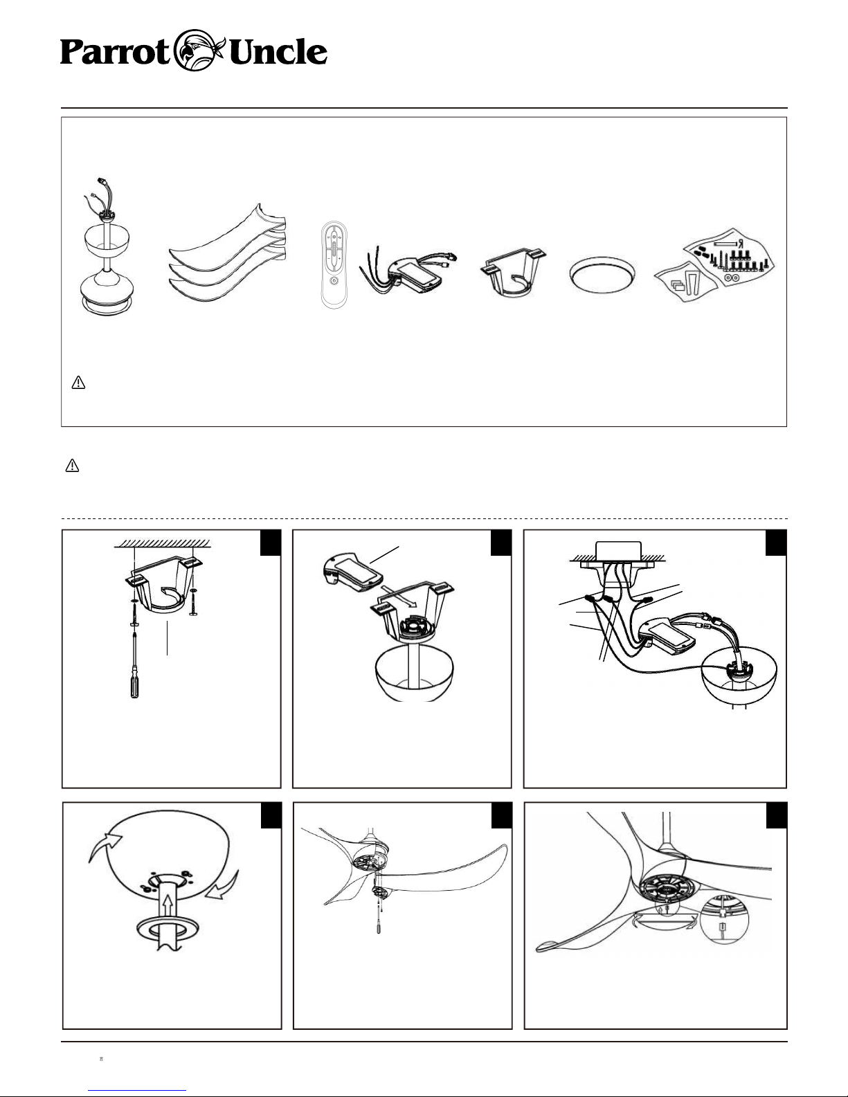
FAN INSTALLATION INSTRUCTIONS
1
UNPACKING YOUR CEILING FAN
-
Open the original carton and verify the following items are available for the standard purchase of this product. It there are any missing or mechanically damaged items, contact the Mercator
Customer Care. Do not throw away the carton or other packaging material as it may be needed if warranty replacement or repair is ever necessary.
Make sure electricity is turned off at the main power box before commencing work. Turn off the power by removing fuse or turning off circuit breaker before installing the fan and replacing the lamps.
• The lowest point on the fan blade must be at least 2.1 metres (7 feet) from the floor.
• Make sure that ceiling joists are strong enough and of adequate size to support the weight of the fan of about 35 kg.
1 x Motor Assembly 3 x Blades 1 x Remote Controller Set
1 x INSTRUCTION BOOK
1 x Mounting Bracket 1 x Light kit 1 x Hardward PACKAGE
· Use of an unapproved remote controller voids the warranty. Therefore do not control the operation of this fan from any remote controller that is not approved by Mercator for use with this fan.
· Do not use solid state controllers.
CAUTION
WARNING
Fan and hanger bracket must be earthed during installation.
Secure the mounting bracket to the ceiling joist or suitable piece
of timber inserted between the ceiling joists. The bracket should
be attached with two wood screws and washers supplied.
Mounting
Bracket
2
Carefully lift motor assembly onto mounting bracket. Install the
ball joint onto the mounting bracket opening. Rotate fan until
notch on downrod ball engages the ridge on the mounting
bracket. This will allow hands free wiring.
Place remote receiver above hanger ball.
Receiver
3
Make the wiring connections for
- signal connector
- receiver’s output connector
- receiver’s input connector
Leave lamp wires connector unconnected for fan without light. Connect live
(AC IN L), neutral (AC IN N) and ground (GROUND) wires to terminal block in
accordance to the wiring label. Isolation switch must be installed.
4
Align key holes on canopy with protruding screw heads from the
mounting bracket. Lift the canopy up to the mounting bracket,
making sure not to break any wire connection. Rotate clockwise
until screw heads engage Tthe key holes fully then tighten the
screws.
5
Align blade holes with holes at the bottom of motor assembly.
Tighten the blade using screws supplied. Repeat the same step
until all blades are installed.
6
Plug in lamp wire connectors.
Install light kit on connecting plate ,
making sure the protruding ends of connectors drop into narrow ends of slots.

Installation & Operating Instructions for the
F6102
Parrotuncle Owner’s Installation ,Manual
WARNING: SHUT POWER OFF AT FUSE OR CIRCUIT BREAKER
Parrotuncle Lighting, 218 Black Tie Lane, Chapel Hill, NC www.parrotuncle.com
Parrot Uncle YOU CAN BE SURE OF are trademarks of Eileen Grays LLC. Used under license by Eileen Grays LLC. All rights reserved. Made in TAIWAN
USING YOUR CEILING FAN WITH REMOTE CONTROL
Pairing Transmitter and Receiver – when 2 or more DC ceiling fan are installed in one location
When two or more fans are located near each other, you may desire to have the receiver/transmitter for each fan set to a different code, so that the operation of one fan does not affect the operation
of the other fans.
The DIP switches for the transmitter (remote hand piece) are located in the battery compartment of the transmitter.
Configuring the DIP switches will allow a unique transmission code assigned to each fan ceiling.
NOTE: Ensure that you have installed an all - poles disconnection switch in the fixed wiring for each fan, when using DIP code function.
NOTE: Ensure power to the Receiver is ON prior to pairing the transmitter with the receiver.
Transmitter/Receiver pairing for ceiling fan 1 :
Turn off both ceiling fans 1 and 2 via the mains supply to the receiver.
Slide the cover of battery compartment of transmitter to access the DIP switches. This will be transmitter 1.
Change the position of the DIP switches in the remote transmitter 1, so that it will be different to transmitter 2. Fig.1
Install the 3V x2 battery in the compartment. Please make sure the polarity of battery is correct.
Turn on the power to receiver 1. Keep the power OFF to receiver 2. (Each ceiling fan must have its own isolation switch, so that only the Ceiling fan that needs to be paired with the transmitter
will be ON).
Press and hold the OFF button of transmitter 1 for 6 seconds within 60 seconds of switching the power to the receiver of Ceiling Fan 1.
Now the transmitter should be paired with the receiver of ceiling fan 1. Turn ON/OFF or change the speed of ceiling fan 1 by the transmitter to check the operation.
Setting DC Ceiling fan 2 :
Turn off both ceiling fans 1 and 2 via the mains supply to the receiver.
Slide the cover of battery compartment of transmitter to access the DIP switches. This will be transmitter 2.
Change the position of the DIP switches in the remote transmitter 2, so that it will be different to transmitter 1. Fig.12
Install the 3V*2 battery in the compartment. Please make sure the polarity of the battery is correct.
Turn on the power to receiver 2. Keep the power OFF to receiver 1. (Each ceiling fan must have its own isolation switch, so that only the Ceiling fan that needs to be paired with the transmitter
will be ON).
Press and hold the OFF button of transmitter 2 for 6 seconds within 60 seconds of switching the power to the receiver of Ceiling Fan 2.
Now the transmitter should be paired with the receiver of ceiling fan 2. Turn ON/OFF or change the speed of the ceiling fan 2 by the transmitter to check operation.t
Note: The pairing of Transmitter and Receiver is not required if only one Ceiling fan is installed. When more than two ceiling fans are installed near each other,
please refer to the instruction above.
Fig. 1
OFF button
Batty
compartment
DIP
switch
Remote Control Buttons
- FAN SPEED CONTROL BUTTON: A 5-10 SECONDS IS REQUIRED TO ALLOW THE DC FAN TO RESPOND TO
THE REMOTE EACH SPEED OR FAN DIRECTION SELECTIONS, AS DC FAN INCORPORATE A SENSOR CONTROL
WHICH CONTROLS THE POWER TO THE MOTOR.
- FAN OFF BUTTON: Press the button to turn the fan off
- REVERSE FUNCTION BUTTON: Press the button to active reverse running function.
The fan must be operating to activate the reverse function.
- LIGHT CONTROL BUTTON: Press the button to turn on/off the light.
THE RECEIVER PROVIDES THE FOLLOWING LEVEL OF PROTECTIONS AGAINSTt
Lock position: the receiver has a built in safety feature to protect against obstruction during operation. The motor
will be locked from operation and will disconnect from power after 30 seconds of interruption. Please remove
obstacles before re-starting. To reset, simply turn off the power supply to the fan motor and re-start.
Over 80W protection: when the receiver detects power consumption which is greater than 80W, the receiver power
will be stopped and operation will immediately discontinue. Turn the receiver power on after 5 seconds to restart
the fan.
○
1
○
2
○
2
○
1
○
3
○
4
1 2 3 45D
○
3
○
4
3Vx2
Fig. 2
Transmitter 1
DIP Switches Set to 00000
Transmitter 2
DIP Switches Set to 00011

Installation & Operating Instructions for the
F6102
Parrotuncle Owner’s Installation ,Manual
WARNING: SHUT POWER OFF AT FUSE OR CIRCUIT BREAKER
Parrotuncle Lighting, 218 Black Tie Lane, Chapel Hill, NC www.parrotuncle.com
Parrot Uncle YOU CAN BE SURE OF are trademarks of Eileen Grays LLC. Used under license by Eileen Grays LLC. All rights reserved. Made in TAIWAN
REPAIRING THE FAN RECEIVER & REMOTE PAIRING
INFORMATION FOR LICENSED ELECTRICIAN AND FAN OWNERS
Should the remote and receiver lose control after installation or during use, the pairing of the remote and the receiver must be repaired. Below are the operating
symptoms and method to repair the pairing of the DC ceiling fan remote and receiver
Note: For your safety, new receiver must be installed by a licensed electrician.
Note: While repairing the DC ceiling fan remote and receiver is in process, the fan operates at highest speed with REVERSE mode automatically for 90 seconds, and
then operates with FORWARD mode for 90 seconds. During the paring process, do not press any key on the remote.
Issues:
Loss of control - Fan only running at high speed after installation
Loss of control - No reverse function after installation
Loss of control - remote cannot communicate with receiver
Solution:
If the fan runs at the highest speed continuously, it means the wiring of the installation is correct. When the fan operated on high speed only, or fails to operate in reverse function or any other
command/s, it is recommended to repair the communication pairing of the remote and receiver. Please follow the steps below:
A. Remove the battery cover of remote, make sure the battery is installed correctly and the LED light indicator will be flashing, it means the remote function is okay.
B. Turn off the main supply to receiver more than 30 seconds and turn on the main supply to receiver again. Press and hold the OFF button remote for 6 seconds within 60 seconds of turning
turn the power to the receiver.
C. Press the buttons on the remote to run the fan. In general, performing point A, B, and C should repair the remote and receiver, and will allow full control of the fan. If not, please kindly do the
next step.
D. The DIP switches of fans are set up at the factory in all up. And we can change DIP switch at any location in 32 options. (Ex. up-up-up-down-down).
E. Please repeat the (A)~(C) steps to check the function.
If the issues still persist after following point (A) to (D), and there is still no control, then please contact the local retailer for a new remote or transmitter.
Please read fault finder before calling for warranty.
1. FAN WILL NOT START
I. Check that mains circuit breakers are in the ON position.
II. Check that isolation wall switch is in the ON position.
III. Check that batteries in the remote handset (if any) are in good condition.
IV. Carry out and complete remote transmitter and receiver pairing process.
V. Check that live, neutral, ground and light (if any) wires from isolation wall switch, remote receiver (if any) through to fan are all wired correctly in accordance with wiring diagram.
VI. Check that all wire connections at wall switch, wire connector and/or terminal block are secured (not loosened).
2. FAN SOUNDS NOISY.
I. Fully tighten light fitting (version with light).
II. Re-tighten all screws on fan blades (do not over tighten).
III. Re-tighten all screws in the hanging bracket and covering plate.
3. MECHANICAL NOISE
I. Let the fan run for about 8 hours for settling in period.
4. FAN TURNS BUT DOES NOT MOVE MUCH AIR
I. The fan may be running in reverse (for fans with reverse running option).
II. The distance from the ceiling to the fan blades is too small.
III. The room may contain items which obstruct the air flow.
IV. The fan may be too small for the size of the room.
5. FAN WOBBLES
Check for wobble after each step.
I. Check that all blade brackets are tightened securely.
II. Most wobble problems result from inconsistent blade level. To check blade level, measure the distance from each blade tip to the ceiling. If measurements are inconsistent, adjustments of brackets will be required.
III. Wobble problem could also result from deviations in distance from blade to blade. To check blade separation, measure the distance from blade tip to blade tip. Should measurements vary, loosen screws connecting
blades and brackets (one at a time) then shift the blade to proper position and re-tighten screws.

Installation & Operating Instructions for the
F6102
Parrotuncle Owner’s Installation ,Manual
WARNING: SHUT POWER OFF AT FUSE OR CIRCUIT BREAKER
Parrotuncle Lighting, 218 Black Tie Lane, Chapel Hill, NC www.parrotuncle.com
Parrot Uncle YOU CAN BE SURE OF are trademarks of Eileen Grays LLC. Used under license by Eileen Grays LLC. All rights reserved. Made in TAIWAN
IMPORTANT FACTS
FAN OPERATION
All electric motors, including fan motors make some noise and may feel hot to touch - this is not a fault. Ceiling fans tend to move during operation as they are not generally
rigid-mounted. Rigid mounted ceiling fans generate excessive vibration and stress on their mountings.
Movement of a couple of centimetres is quite normal and does not suggest the fan will fall down.
Please note - all ceiling fans are not the same, even in the same model some may move more or less than others.
Fan lights can rattle, if they are not supplied with the fan. They are not covered by warranty.
A ceiling fan is an environmentally smart choice when it comes to cooling as well as helping to warm your room. You should see a reduction in both cooling and heating
costs by regular use of your fans.
Do not hesitate to use your fans in both summer and winter months.
In summer fans should be set to spin in anti clockwise direction blowing down cool breeze.
In winter, fan should be set to spin in clock wise direction so that an upward airflow will push warm air off the ceiling and circulate it downwards into the living areas. In
winter months use the fan on a lower speed than in summer.
NORMAL WEAR AND TEARt
Threaded components working slightly loose, or blade carriers becoming slightly bent due to vigorous cleaning or bumping can cause extra wobble and noise. This is not
covered under warranty, but a little care and maintenance can reduce or prevent this problem.
NIGHT NOISES
This is the biggest cause of service calls, which are outside the manufacturer’s warranty. If a fan has a fault it will be noticeable at all times. Naturally when everything is
quiet at night you will be more inclined to hear small noises, which may not be noticeable at other times. Even slight signals super imposed in your electricity supply for off
peak hot water control may cause a change in the fan motor noise. This is normal.
Modelo: F6102
CARACTERISTICAS ELECTRICAS:
Parrotuncle Lighting, 218 Black Tie Lane, Chapel Hill, NC www.parrotuncle.com
Parrot Uncle YOU CAN BE SURE OF are trademarks of Eileen Grays LLC.
Used under license by Eileen Grays LLC.
All rights reserved.
Made in TAIWAN
 Loading...