

Paromax RAFAEL 55 Maintenance Manual
RAFAEL 55
.
Paromax
inc
Report No. 120-S-01B-2
Tested to: ASTM E1509-04,
ULC S627-00,
ULC/ORD C1482-M1990
IMPORTANT : Read the manual before using the Rafael
USER MANUAL & MAINTENANCE
WARNING:
PROFESSIONAL INSTALLATION
Improper installation, adjustment, alteration, or
maintenance can cause injury, property damage,
IS HIGHLY RECOMMENDED
or loss of life. For assistance or additional
information, consult an authorized dealer.
Manufactured by Paromax Inc.
900 Michèle-Bohec Suite 101
Blainville Qc
Canada J7C 5E2
IMPORTANT INFORMATION:
Model:
Serial Number:
Purchase date:
Purchased from:
Please note your serial number when
calling for technical support (see page 4)
Ver. RAE 11.9A September 2011
MESSAGE TO NEW OWNER
Thank you ! We Appreciate Your Business
The quality of execution of each of our stoves will provide you peaceful years of comfort.
Three steps to follow for the safest and most efcient performance of the stove.
Congratulations!
1- Install it properly 2- Operate it correctly 3- Maintain it regularly
PAROMAX : The Passion of Renewable Energy
The Rafael is certied to burn: Premium And Low Grade (high ash) Wood
Pellets, Corn Kernels And Wheat Grains.
WARNING: Use Fuel listed Only. That carbon monoxide can result from using fuels
that are not recommended by Paromax.
Safety Advisory:
-A re may result if your appliance is not properly installed. For your safety, follow the installation
instructions.
-Contact local ofcials about restrictions and installation inspection requirements in your area.
-Local regulations and requirements can supersede those specied in this manual if more
stringent.
The authority having jurisdiction (such as municipal building department, re
department, re prevention bureau, etc.) should be consulted before installation to determine the need to obtain a permit.
The installation of this unit must be in accordance with these instructions. Read them
carefully before installation. Keep this manual handy for future reference.
Package contents
Quantity Description
1 User manual and Installation
1 AC Power Inlet cord
1 Measuring 2 ½ Plastic Cup
1 Black alligator clip for battery
1 Red alligator clip for battery
1 Fuse 500MA
1 7 amp battery back up
1 Poker tool for burner
2
1 Ash pan
WARNING: -Please read this entire
manual before installation and use
of this multi-fuel burning room heater. Failure to follow these instructions could result in property damage, bodily injury or even death.

-Package contents of the RAFAEL ............................................
-Certication label ......................................................................
-Safety instructions ....................................................................
-Installation
Table contents
page 2
page 4
page 5
-Unit location .............................................................................
-Chimney types .........................................................................
-Mobile home installation ..........................................................
-High elevation ..........................................................................
-Negative pressure in the house ...............................................
-Outside inlet Instalation.............................................................
-Pressure regulator ...................................................................
-Battery supplied with unit .........................................................
-Level your unit .........................................................................
-Thermostat installation ............................................................
-Clearance and dimensions diagram ........................................
-Clearance table ........................................................................
-Chimneys schema ....................................................................
-Control panel functions ............................................................
-Procedures steps for start up
-First start up .............................................................................
-To turn on your unit ..................................................................
-Instructions for burning wood pellets........................................
-Instructions for burning corn or wheat......................................
-First use of the RAFAEL with corn or wheat ............................
-Preparing the unit for corn or wheat.........................................
-Clinker prevention ....................................................................
-Controlling the fuel bed (embers) level ....................................
-How to measure the fuel bed height ........................................
-Pressure gauge setting ............................................................
-Fuel consumption correction ....................................................
-Programming fuel consumption ...............................................
-Thermostat mode .....................................................................
-Mixing mode .............................................................................
-Stove component’s maintenance program ..............................
-Maintenance guide ..................................................................
-Error codes ..............................................................................
.
-Troubleshooting ........................................................................
-Technical data ...........................................................................
-Electrical diagram ....................................................................
-Replacements parts .................................................................
-Warranty ...................................................................................
..
page 6
page 6 & 7
page 7
page 7
page 7
page 8
page 8
page 8
page 9
page 9
page 9
page 10 & 11
page 11 & 12
page 13 to 15
page 16
page 16 & 17
page 17
page 18
page 18
page 18
page 18
page 19
page 19
page 20
page 20
page 21
page 21
page 21
page 22
page 23 to 27
page 28
page 29 to 32
page 33
page 34 & 35
page 36
page 37
3
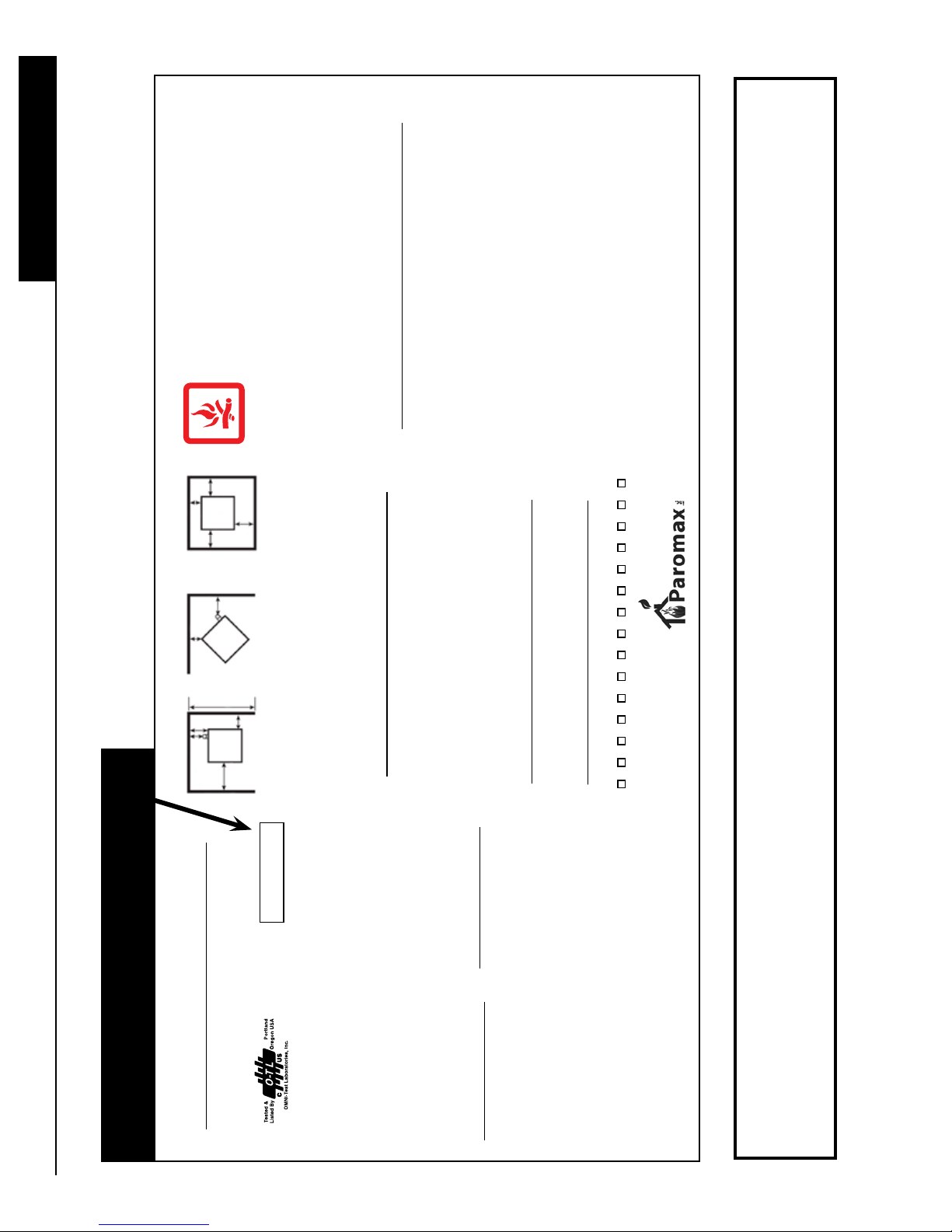
Certication label
-HOT WHILE IN OPERATION.
-DO NOT TOUCH, KEEP CHILDREN, CLOTHING AND
FURNITURE AWAY.
-CONTACT MAY CAUSE SKIN BURNS.
-SEE NAME PLATE AND INSTRUCTION.
-DO NOT OVER FIRE, IF HEATER OR CHIMNEY CONNECTOR
GLOWS, YOU ARE OVER FIRING.
RA-AM-CL-01B
Made in Canada/Fabriqué au Canada
DO NOT REMOVE THIS LABEL/NE PAS ENLEVER CETTE ÉTIQUETTE
CAUTION
*6”
CM
15.2
Stove
6”- 15 CM
*6”
CM
NON COMBUSTIBLE
15.2
FLOOR PROTECTION
ADJACENT WALL
3”
SEE
7.6 CM
Stove
4”
10 CM
30”
MAX
76.2 CM
6”
15
CM
3”
Stove
7.6 CM
BACKWALL
SEE
NOTE
***8”
FRONT
6” - 15.2 CM
NOTE
**3”
20 CM
-INSPECT AND CLEAN CHIMNEY AND CONNECTOR FREQUENTLY.
7.6 CM
-UNDER CERTAIN CONDITIONS OF USE, FLY ASH BUILDUP MAY OCCUR RAPIDLY.
-MOVING PARTS MAY CAUSE INJURY.
INSTALL AND USE ONLY IN ACCORDANCE WITH INSTALLATION AND OPERATING
ASH REMOVAL DOORS TIGHTLY CLOSED DURING OPERATION. OPERATE ONLY
WITH DOORS CLOSED.
WARNING: RISK OF SMOKE AND FLAME SPILLAGE. KEEP VIEWING AND
INSTRUCTION. NOTE: REGARDLESS OF THE STOVE CLEARANCE, VENT PIPE MUST
ALWAYS HAVE A 3” OR 7.6 CM CLEARANCE. USE ONLY MULTI FUEL VENT PIPE TYPE
PL LISTED HAVE 3” TO 4” OR 7.6 TO 10.1 CM INSIDE DIAMETER. CHIMNEY AND
CONNECTOR LISTED FOR MULTI-FUEL VENT ONLY. FLOOR PROTECTION MUST BE
3/8” OR 1 CM MINIMUM THICKNESS NON-COMBUSTIBLE MATERIAL OR EQUIVALENT,
-TOUT CONTACT PEUT CAUSER DES BRÛLURES À LA PEAU.
-GARDEZ LES ENFANTS, LES VETEMENTS ET LES MEUBLES À UNE
DISTANCE CONSIDÉRABLE.
-LISEZ L’ÉTIQUETTE ET LES INSTRUCTIONS.
-NE PAS SURCHAUFFER, SI L’UNITÉ OU LES TUYAUX DE CHEMINÉE
ROUGISSENT, C’EST QUE VOUS SURCHAUFFEZ.
-INSPECTEZ ET NETTOYEZ LA CHEMINÉE ET LES TUYAUX FRÉQUEMMENT.
-SOUS CERTAINES CONDITIONS D’USAGE, LES RÉSIDUS DE CENDRE
PEUVENT SE FAIRE RAPIDEMENT.
CAUTION: OPERATE THIS UNIT ONLY WITH THE FUEL HOPPER LID
CLOSED. FAILURE TO DO SO MAY RESULT IN EMISSIONS OF PRODUCTS OF
COMBUSTION FROM THE HOPPER UNDER CERTAIN CONDITIONS. MAINTAIN
4” - 10 cm
AVIS: -CHAUD LORSQU’EN OPÉRATION. NE PAS TOUCHEZ.
HOPPER SEAL IN GOOD CONDITION. DO NOT OVERFILL THE HOPPER
-TOUTES PIÈCES MOBILES PEUVENT CAUSER DES BLESSURES.
ATTENTION: IL Y A RISQUE DE FUMÉE ET DE FLAMME. GARDEZ LA
4” - 10 cm
5” - 12.7 cm
U.S. ENVIRONMENTAL PROTECTION AGENCY
Certified to comply with July 1990 particulate emission standards.
*** Unit to sidewall required 8” or 20.3 cm clearance for access to control.
*** 8” ou 20.3 cm est exigé entre l’unité et le mur pour L’accès au contrôle.
EXTENDING BENEATH HEATER AND TO THE FRONT/SIDES/REAR AS INDICATED.
** SIDE WALL TO UNIT 3” - 7.6 cm
BACK WALL TO UNIT 5” - 12.7 cm
CORNER TO UNIT
INSTALLER ET UTILISER SEULEMENT CONFORMEMENT AU GUIDE D’INSTALLATION
ET D’INSTRUCTION. NOTE: PEUT IMPORTE L’ESPACE LIBRE DE L’UNITÉ, LE TUYAU
DE LA CHEMINÉE DOIT TOUJOURS AVOIR 3” OU 7.6 CM D’ESPACE LIBRE. UTILISER
SEULEMENT UNE CHEMINÉE DE TYPE PL POUR MULTI-COMBUSTIBLE LISTÉE DE 3”
À 4” OU 7.6 À 10.1 CM DE DIAMÈTRE INTERNE. LA CHEMINEE ET LES CONNECTEURS
DOIVENT ÊTRE LISTÉ POUR MULTI COMBUSTIBLE SEULEMENT. LE PROTECTEUR DE
PLANCHER DOIT ÊTRE 3/8” OU 1 CM D’ÉPAISSEUR MINIMUM DE MATÉRIEL NON-
COIN DE L’UNITÉ À L’UNITÉ
COMBUSTIBLE OU L’ÉQUIVALENT, S’ÉTENDANT EN DESSOUS DE L’UNITÉ ET AU
DEVANT/CÔTÉS/ARRIÈRE COMME INDIQUÉ.
** MUR DE CÔTÉ À L’UNITÉ 3” - 7.6 cm
MUR ARRIÈRE À L’UNITÉ
PORTE DE VUE ET CELLE DES CENDRES FERMÉE HERMETIQUEMENT
DURANT L’OPÉRATION. OPÈRER TOUJOURS AVEC LES PORTES FERMER.
FERMÉ. SINON IL PEUT EN RÉSULTER, DES ÉMISSIONS DE PRODUITS DE
COMBUSTION DE LA TREMIE SOUS CERTAINES CONDITIONS. MAINTENEZ
LE COUVERCLE DE LA TREMIE EN BONNE CONDITION. NE REMPLISSEZ
PAS LA TREMIE TROP PLEINE.
AVIS: OPÉREZ CET APPAREIL AVEC LE COUVERCLE DE LA TREMIE
DATE OF MANUFACTURE/ DATE DE FABRICATION
Manufactured by/
AGENCE DE PROTECTION ENVIRONNEMENTALE DES ÉTATS-UNIS
Certifier et conforme aux standards de particule d’émission de juillet 1990
2010 2011 2012 Jan. Feb. Mar. Apr. May June July Aug. Sep. Oct. Nov. Dec.
Manufacturé par:
Blainville, QC, Canada J7C 5E2
RA11-0000
Serial No./
Nu. De Serie
Model: Rafael 55
Tested to: ASTM E1509-04, ULC S627-00,
INSTALLATION INSPECTION IN YOUR AREA.
Listed Room Heater, Pellet, Corn, Wheat Fuel-Burning Type
Unité Cataloguées; Pour Combustible Listé, Granule de Bois, Maïs, Blé,
CONTACT YOUR LOCAL BUILDING OR FIRE OFFICIAL ABOUT RESTRICTIONS AND
Serial number of the unit
Also SUITABLE FOR MOBILE HOME INSTALLATION Pursuant to (UM) 84-HUD
RESTRICTIONS ET DE L’INSPECTION DES INSTALLATIONS DANS VOTRE QUARTIER.
CONTACTEZ VOTRE BUREAU DE CONSTRUCTION OU DES INCENDIES AU SUJET DES
Peut Être UTILISÉE POUR L’INSTALLATION DANS UNE MAISON MOBILE Sous (UM) 84-HUD
Report No./Rapport Nu.: 120-S-01B-2
‘‘PREVENT HOUSE FIRES’’
4
ULC/ORD C1482-M1990
Type of Fuel: Wood Pelletized, Corn, Wheat
WARNING: Only Use Fuel listed above.
Electrical Rating: 120V, 1 amp, 60 Hz
Input Rating: 7,600 to 34000 BTU Typical
NOTE: Replace glass only with 5 mm
ceramic.
Component required for residential and
mobile home installation: Listed multi-fuel
vent type PL and component for outside air
Refer to manufactures installation and
operating instruction also.
CAUTION: Special methods are required when
passing chimney through a wall or ceiling.
Follow the pipe manufacturer’s instructions and
local building codes for clearance to combusti-
bles required for the installation of the vent pipe
being used. Do not pass chimney connector
through a combustible surface. Do not connect
this unit to a chimney flue serving another
appliance.
for mobile home. Refer to manual.
DANGER: Risk of electrical shock.
Disconnect power before servicing unit. Do
not route power cord beneath heater.
Modèle: Rafael 55
Testé à: ASTM E1509-04, ULC S627-00,
ULC/ORD C1482-M1990
Type de Gaz: Granule de Bois, Maïs, Blé
ATTENTION:Utilisé les Combustibles Listé
Évaluation Électrique: 120V, 1 amp, 60 Hz
Évaluation Énergétique: 7,600 to 34000 BTU
‘‘PRÉVENTION DES FEUX DE MAISON’’
Se référer au manuel d’installation du manufac-
turier et d’instruction.
AVIS: Des méthodes spéciales sont exigées
lorsqu’une cheminée passe à travers d’un mur
ou d’un plafond. Suivez les instructions du man-
ufacturier de tuyau et les codes locaux de con-
WARNING: (Mobile Home)
Outside air inlet must be provided for combus-
tion and be unrestricted while unit is in use.
NOTE: Remove outside sections of the chim-
ney when displacing the mobile home. Refer to
manual for kit FA01. Outside air is required.
struction pour l’espace libre des combustibles
Typique
NOTE: Remplacez la vitre avec de la
Céramique de 5mm seulement.
Produits exigés pour l’installation dans une
maison résidentielle et mobile: cheminée
pour multi-combustibles listée PL et une
prise d’air extérieure pour maison mobile.
DANGER: Il y a risque de choc électrique.
Débranchez l’unité avant de faire la mainte-
nance. Ne pas faire passer la corde
exigé pour l’installation du tuyau de ventilation
en usage. Ne passez pas le tuyau connecteur
de cheminée à travers une surface combusti-
ble. Ne connecter pas cet appareil à un tuyau
de cheminée servant un autre appareil.
ATTENTION: (Maison Mobile)
Une prise d’air extérieur doit être fourni pour
l’entrée du brûleur et doit être sans restriction
lorsque l’unité est en opération.
NOTE: Enlever les sections de la cheminée lors
du transport de la maison mobile. Se référer au
manuel d’instructions pour le kit FA01. A besoin
électrique en dessous de l’unité.
Here is a COPY of the certication label apposed on each Rafael. You can then examine the contents.
de l’air extérieur.
The security label is located on the back panel of the stove.
SAFETY PRECAUTIONS
01- DO NOT BURN GARBAGE OR FLAMMABLE FLUIDS SUCH AS GASOLINE, NAPHTHA OR ENGINE OIL AND
DO NOT USE CHEMICALS OR FLUIDS TO START THE FIRE
02- Do not store any combustibles near to the unit in operation. Minimum clearance behind the unit and the
combustibles are 4 feet. Store the combustible in a dry place
03- Do not use gasoline, gasoline-type lantern fuel, kerosene, charcoal lighter uid, or similar liquids to start or freshen
up a re in this unit. Keep all such liquids well away from the unit while it is in use.
04- Do not operate the stove if the burn pot overll with fuel. Turn off the stove and refer to the maintenance instruction.
05- Do not strike or slam shut the glass door, it may damage or crack the glass.
06- Do not use a substitute materials or components. Always replace by a Paromax part.
07- Do not operate the unit without burn pot ” tube” or in invert position (upside down).
08- Do not burn untreated wood only. Other materials such as wood preservatives, metal foils, coal, plastic, garbage,
sulphur, or oil may damage the catalyst.
09- Do not add combustible to the burn pot by hand when the unit is in operation.
10- Do not lay the ash pan on combustible oors when the ashes are hot.
11- It is very important to ensure that the stove is installed in a safe manner. Be aware of re prevention rules and laws in your
area. All applicable National and Local codes must be met and complied with. Notify your insurance company of this stove.
Do not use makeshift methods or compromise in the installation.
Safety instructions
12- We recommend a dealer authorized by Paromax to install your stove. If the stove is installed by an unauthorized installer,
Paromax will not be held responsible for any malfunction related to the chimney including a poor performance of the stove.
13- Please note the battery comes shipped inside the ash pan. Please remove the battery before start-up.
14- The electrical connection required with the stove consists of AC power inlet cord to plug into a standard wall outlet
(120 volts AC North America or 240 volts AC Europe) with ground connection.
15- It is strongly recommended to install a smoke detector and an ABC type re extinguisher near the unit. Using a power
surge protector bar helps protect the electrical components of the unit and is highly recommended.
16- Your stove requires periodic maintenance and cleaning. Failure to maintain your stove may lead to a poor
performance, smoke spillage in your home or even a more dangerous situation.
17- To start your stove, always use a specied and approved re starter gel (gel approved for multi-fuel stove). Never
use a ammable liquid like gasoline, barbecue re starter or alcohol. Failure to comply with this may create a hazardous
situation and will void all warranties.
18- Never attempt to re-light your stove until the unit has fully cooled down. Never start your unit with a gel re starter when
the burner is still hot, it could cause severe burns. Wait until the unit and the burner are completely cold before you turn it
back on.
19- Manual feeding (primer) should only be used to initiate fuel supply to the burner when the hopper is empty. Do not use the
manual feed procedure to start your unit, it will cause smoke inside the combustion chamber.
20- Ensure that the ash pan door is securely closed at all times. Air pressure could ignite the fuel accumulated in the burn-pot
creating an overdraft condition in the combustion chamber altering the performance of the burn-pot.
21- The fuel supply may not work if the main door, ash tray door or hopper door are not properly closed, the combustion
chamber must be under negative pressure.
22- Stove must be cold before any attempt to clean the main glasses. Do not use detergent containing abrasives to clean
the windows or any other parts of the stove. Use only recommended products found at your local hearth shop for this
type of cleaning.
23- Ashes must be disposed in a metal container with a tight lid and placed on a non-combustible surface well away from the
house. Wear gloves when handling or emptying the ashes as it can still be very hot.
24- Never use a vacuum cleaner to remove ashes from the stove or the burner or the ash pan, unless the stove is cold for
several hours.
5

Unit location
For optimum benet with your appliance, speak to an authorized Paromax Dealer concerning the unit location.
The location for your appliance can be a factor in how it will perform. Choose an interior location where the vent
will not be affected by any external interference, ex; trees, bushes, walls or fencing (refer to “Vent Termination
Installation
Requirements” section at page 10). Install the stove according to recommendations made on “clearances” section
at page 10 or according to the safety label xed on the unit.
You can use the wall behind the unit to pass the chimney system through a wall, or partition of combustion con-
struction. The installation shall conform to CAN/CSA-B365. Paromax does not recommend to connect the Rafael
to an existing chimney type PL of maximum 4” or 10.2 cm inner diameter. Use only an approved double-walled 3”
inner diameter with horizontal outlet cap inside the existing chimney (see picture of cap on page 12).
Ensure that all clearances to combustibles are met as per the safety label and the diagrams on “Clearances”
section at page 9.
This appliance may need outside air if there is a negative pressure within the room where the installation takes
place. Make sure the outside air supply for the burner does not come from a garage, an attic or any restricted
non-ventilated space. Air must come from the outside of the house and directly into the room where the stove is
installed. If using an outside air supply, the unit must be bolted to the oor. See mobile home installation for more
information. Refer to Outside inlet Installation on page 8.
The ooring under the stove must be a non-combustible material, i.e. cement, ceramics, etc, and must extend of at
least 6” or 15.2 cm for the sides and 6” or 15.2 cm for the front. Refer to the diagrams on “Clearances” section at
page 9.
A requirement that a chimney connector shall not pass through an attic or roof space, closet or similar concealed
space, oor or ceiling. Do not use different brand or models of vent pipe on the same vent pipe installation.
WARNING: DO NOT INSTALL A FLUE DAMPER IN THE EXHAUST VENTING SYSTEM
OF THIS UNIT. DO NOT CONNECT THIS UNIT TO A CHIMNEY FLUE SERVICING ANOTHER APPLIANCE. DO NOT CONNECT TO ANY DISTRIBUTION DUCT OR SYSTEM.
Chimney types
IMPORTANT : Always use a double wall 3” or 7.6 cm or 4” or 10.2 cm PL type chimney approved for venting
wood pellets fuel or agriculture fuel. Use another chimney size will give incorrect results readings. This may even
cause a malfunction of your device. These cases are not covered by warranty. A minimum of three metal screws
is recommended to secure each joint of the chimney. A tight seal (silicone or aluminum tape) is recommended on
each section of the chimney to prevent smoke leakage and odors. Gas tight joints : The pipe connecting to the
unit and the outer wall joints located between the pipes also need to be sealed with high temperature silicone or
aluminum tape. The maximum height chimney 35 feet. Use a wall thimble for ammable wall or collar for cement
wall. Seal the exterior chimney with silicone to create a vapor barrier.
It is not recommended to seal the inner walls joints already containing a pre-installed silicone or rubber sealant
by the manufacturer of the chimney. Do not use a perforated outer wall chimney ue channeling fresh air to the
burner.
WARNING : DO NOT INSTALL IN SLEEPING ROOM
CAUTION: THE STRUCTURAL INTEGRITY OF THE MANUFACTURED
HOME FLOOR, WALL AND CEILING/ROOF MUST BE MAINTAINED
6
Chimney types (continued)
Since this is a multi-fuel stove, it is recommended to choose an approved venting system. If you choose wood pellets, a double wall 3’’ or 7.6 cm stainless steel pipes are recommended. For agriculture fuel, it is recommended to
use double wall PL type 3’’ or 7.6 cm stainless with higher quality durability. Refer to the vent pipe manufacturer for
more details.
Do not use a non-approved pipe for your vent system. i.e., Dryer vent, “B” vent for gas vent, PVC/plastic pipe or
single wall chimney system.
Please note that the length of a horizontal venting system shall not exceed 24’’.
Always vent to the outside atmosphere and never into enclosed spaces, i.e. garage, car port etc. Venting systems
can generate heat and smoke.
WARNING: HOT UNIT WHILE IN OPERATION.
KEEP CHILDREN, CLOTHING AND FURNITURE AWAY.
ANY CONTACT MAY CAUSE SKIN BURNS
Installation
Mobile home installation
Use PL type chimney for immediate evacuation outside the mobile home. Refer to the chimney diagram for proper
exhaust installation. The space heater is to be connected to a factory-built chimney conforming to CAN/ULC-S629,
standard for 650 degrees F. For proper clearances, remove outside sections of the chimney when displacing the
mobile home. Outside air inlet must be provided for combustion and be unrestricted while unit is in use. Refer to
ouside inlet installation on page 8. The stove must be securely fastened to the oor by using one bolt in the front
and two bolts in the back of the unit.
Recommendation: Chimney installation in a windy area must rise above the roof.
It may be normal for ice build-up around the cap during cold or windy days.
High elevation
High altitude reduces air capacity to the burner. To help increase the air speed, a vertical chimney above the roof is
recommended to create a natural air ow. Refer to the chimneys diagrams on page 11 and 12.
Negative pressure in the house or starvation air
The use of a bathroom fan, dryer, kitchen hood fan, etc., can create negative pressure, especially in new air tight
homes. Combined, these fans consume three times more powerful than the combustion fan on the RAFAEL, and
may create a signicant drop of pressure therefore a lack of air to the burner that may cause a re extinguishing. Paromax suggest you take a gauge reading before, during and after the use of your appliances and/or fans
to check the pressure variations. If the pressure changes, Paromax recommends installing an outside air intake.
Refer to fresh air installation for more information.
7
Outside inlet Installation (FA01 kit)
Use a coupling to increase 1” to 2” or 5 cm pipe thread, install a one way valve, maximum length is 5 feet or 12.7
cm. For more then 5 feet, increase to 2 1/2 or 6.3 cm diameter for a maximum of 10 feet total. Install cap with a
grill to prevent rodents entering. Note seal all joints and most important seal the wall outlet to prevent water entering. To view air inlet location, refer to page 9 (width picture).
Installation
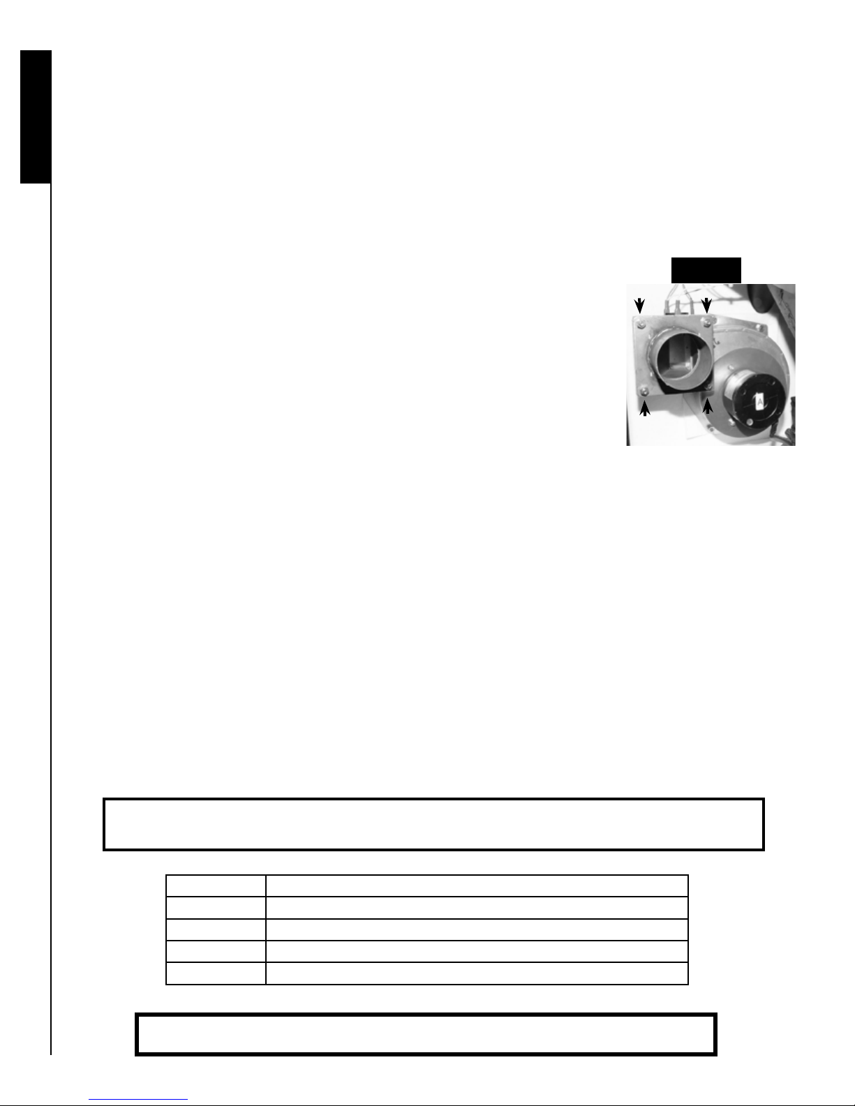
Pressure regulator
Image 1
A chimney installation with natural draft may create a malfunction due to high pressure. If necessary, obtain an air reducer plate from your dealer.
To install the plate regulator, refer to the image 1 to view the air outlet. There are 4
nuts and bolts to be removed from the air outlet by using a 7/16” wrench or 11 mm
socket. Install the pressure regulator on the combustion fan air outlet, taking care to
replace the white seals on each side of the pressure plate. Replace the bolts, washers and nuts on the air outlet and tighten the bolts for a hermetic pressure regulator.
Battery supplied with the unit
This battery will allow uninterrupted operation of your stove in case of power failure. Please note that this system
does not replace the standard electrical power of 120 volt AC of the unit. This is a battery backup feature. When
fully charged, it can last 4 hours or less depending on heat level setting (1-5) used. It is recommended to always
leave the battery connected. The battery will be recharged when the power comes back.
For an extended performance, we suggest purchasing a bigger 12 volts car battery for a longer use.
If a power outage occurs for more than 3 seconds and there is no battery connected , the fans will stop and there
is a risk of smoke. When electricity is restored, the control panel will display the error code VOLT 2. If the unit is
still hot, the fans will start to cool down the unit. In case of interruption of less than 3 seconds, the unit could continue to operate normally.
Option: To use the unit on 12 volts continuously as your main power, we recommend to by-pass the power inverter.
Disconnect inverter the black wire identied on COM and the red wire identied on V1 on the power inverter and
then connect these wires directly to the 12 volts DC source. The Warranty does not cover any polarity inver-
sion that may damage the control panel (see picture 35 on page 34).
Recommendation: Your battery is provided with an insulation to prevent ground
contact. Never settle a battery on the oor cause there is a discharge risk.
Step Battery connection order to follow
1 Connect the red clip to the positive battery terminal +
2 Connect the black clip to the negative battery terminal -
3 Connect the battery red wire to the unit red wire.
4 Connect the battery black wire to the unit black wire.
8
WARNING: Children should be kept away from the hot unit.
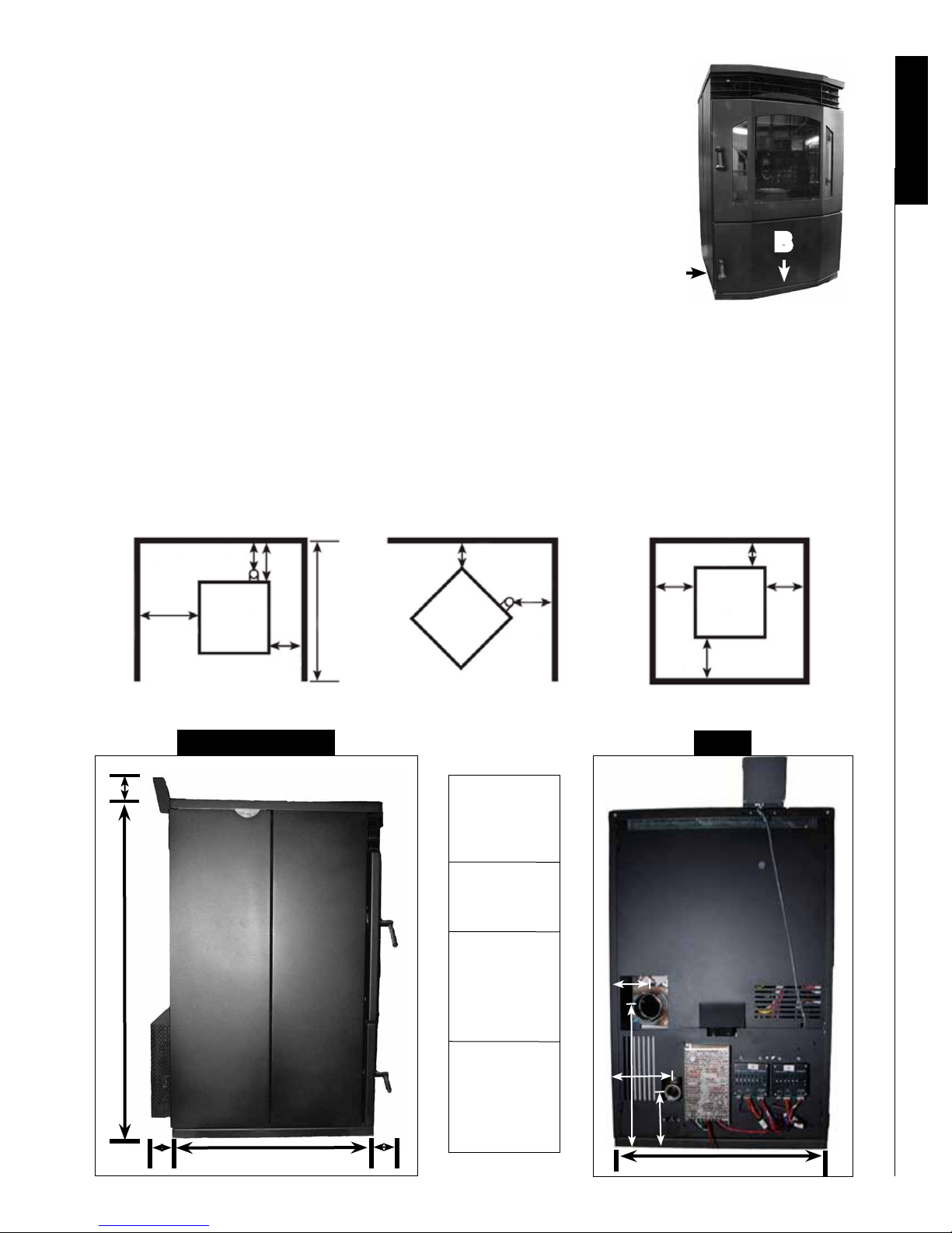
Leveling your unit
It is essential to level your unit for a stable fuel bed. First put a level on
the side of the base (letter A) and use metal “spacer” to adjust the lowest
side. And then, level the front by placing the level on the front of the base
(B). When burning agriculture fuel, Paromax suggests increasing the height
of the front of the unit by 1/4” to 3/8’’. This modication helps to reduce ash
accumulation in the front of the burner.
B
A
Thermostat installation for the RAFAEL
For thermostat function, you must purchase a low voltage (millivolts) thermostat or a thermostat with battery (AA or
AAA batteries or 9 volt) or a mercury thermostat or a radio frequency wireless thermostat. How to connect to the
unit: Use a conductive 2 wires cable (telephone wire) size 22 or 24 type. Purple wires to connect the thermostat
are located near the control panel inside the unit. See thermostat operation mode on page 21
Clearance of the RAFAEL
NON-COMBUSTIBLE
BACKWALL
SEE
NOTE
12”-
30 CM
3”-
7.6 CM
UNIT
6”-
15
CM
12”-
30 CM
38”-
96.5 CM
MAX
ADJACENT WALL
4”-
10 CM
3”-
7.6 CM
UNIT
SEE
NOTE
FLOOR PROTECTOR
6”- 15 CM
*6”-
15.2
CM
UNIT
*6”- 15.2 CM
*6”-
15.2
CM
FRONT
Installation
Height and Depth
4” - 10.1 cm
34 3/4” - 88.2 cm
A B
23 1/4 - 59 cm
Safety
cover
A = 2 1/2”
6.3 cm
Handles
B = 3/4”
1.9 cm
Exhaust
C = 3 1/2”
8.9 cm
D = 14 1/2”
36.8 cm
Fresh air
E = 6 1/4”
15.8 cm
F = 5 7/8”
14.9 cm
D
C
E
F
22 3/8 - 56.8 cm
Width
9
IT IS RECOMMENDED THAT YOUR PELLET STOVE BE INSTALLED
BY A PAROMAX AUTHORIZED DEALER/INSTALLER.
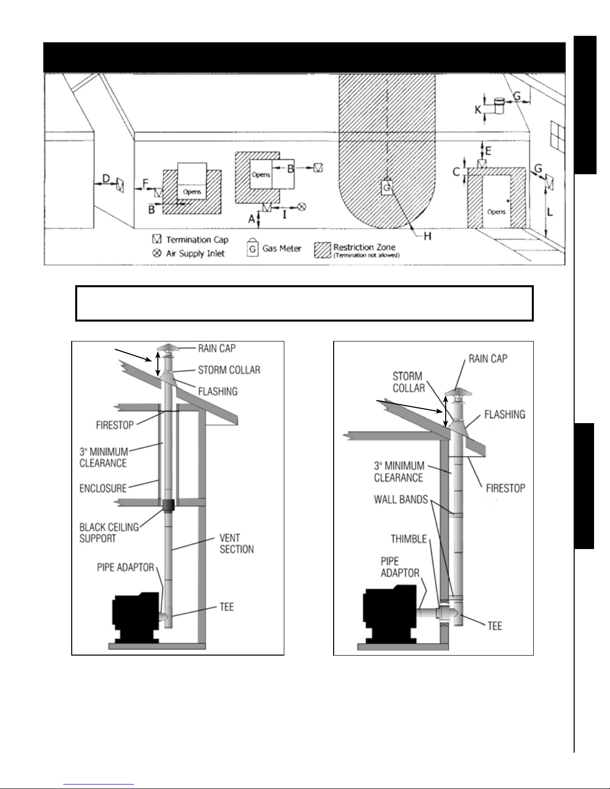
CLEARANCE TABLE : Use in conjunction with diagram below for allowable exterior vent
locations for both horizontal and vertical terminations. Clearances may only be reduced by means
Installation
approved by a regulatory authority.
Minimum Description
A
A
B
C
D
E
F
G
H
24” / 61 cm
12” / 30.5 cm
48” / 122 cm
12” / 30.5 cm
24” / 61 cm
24” / 61 cm
12” / 30.5 cm
12” / 30.5 cm
36” / 91.5 cm
Above lawns, top of plants, wood or any other combustible materials.
Above non-combustible surface such as cement and gravel.
From beside/below any door or window that may be opened.
From above any door or window that may be opened.
To any adjacent building, fences and protruding parts of the structure.
Below any eaves or roof overhang.
To outside corner.
To inside corner, combustible wall (vertical & horizontal terminations).
To each side of center line extended above natural gas or propane meter/
regulator assembly or mechanical vent within a height of 15’ / 4.5 m above
the meter/regulator assembly.
I
36” / 91.5 cm
J
12” / 30.5 cm
From any forced air intake of other appliance.
Clearance to non-mechanical air supply inlet to building or combustion air
inlet to any appliance.
K
24” / 61cm
Clearance above roof line for vertical terminations.
NOTES :
1. Do not terminate the vent in any enclosed or semi-enclosed areas that can build up a
concentration of smoke.
2. Vent surfaces can become extremely hot. Keep children away from such areas. Non-combustible
shielding or guards may be required.
3. Termination must exhaust above sea level and the inlet elevation. It is recommended to have a
short vertical run which will help in the event of total power failure.
4. If the unit is incorrectly vented or the air to fuel mixture is out of balance, a slight discoloration of
the exterior of the house might occur. Since these factors are beyond our control we offer no
guarantee against such incidents.
5. When installing into an existing masonry chimney, you will probably need a short horizontal
section to clear the lintel and allow the hopper lid to open.
6. Vent terminations shall not be recessed into walls or siding.
7. A vent shall not terminate directly above a sidewalk or paved driveway which is located between
two single family dwellings and serves both dwellings.
8. If the vent termination is children accessible, a certied guard shall be installed as specied in
CGA B149 installation Code in Canada. Note: Local codes or regulations may require different
clearances.
10
Minimum clearances table for a wall installation
INSTALL VENT AT CLEARANCES SPECIFIED BY THE VENT MANUFACTURER
Refer to the norm CAN/CSA-B365-01 before installing the vent.
Clearances table
12” or
30.5 cm
MIN.
Stove
12” or
30.5 cm
MIN.
Stove
Chimney types
Equivalent Vent length (EVL)
Venting your unit is crucial for optimum operation. There are ve different installation examples recommended by
Paromax.
The unit uses the combustion fan to move air from the exhaust to the chimney. (Next on page 12)
11

Restriction may come from several different items. Each 45 degree elbow = 3 EVL
Each 90 degree elbow and tee clean out = 5 EVL
Each foot of horizontal run = 1 EVL
Each foot of vertical run = 0.5 EVL
Elevation above 3000 ft with an EVL of 7 must adapt to 4 inch vent pipe.
If your installation is below 3000 ft: Rule of installation is to have the sum of the EVL 15 or less. For a sum of more
than 15 EVL,install a 4” or 10.1 cm vent pipe.
Chimney types
Total of
Vertical cap
recommended
Total of
14.5 EVL
14.5 EVL
Sealing off the
top and bottom
of existing
chimney with
Stove
5 feet minimum on vertical vent
the new pipe is
Stove
recommended
3” or 7.6 cm pipe in an existing chimney Alcove installation
vertical
cap
5 feet minimum on vertical vent
12
3” clearance to the
chimney type A top
Storm collar
Flashing
3” clearance
Support
bracket
Outside
air
Type A chimney
Type A chimney
clearances speci-
ed in chimneys
instructions
ceiling support
L Vent to class A
chimney adaptor
Hearth pad
6”
Minimum alcove
Maximum
alcove
depth
38” or
96.5cm
Minimum
alcove
side
12” or
30.5cm
The ooring under the unit for alcove must be a non-combustible
material, i.e. cement, ceramics, etc, and must extend of at least 6” for
the sides and 12” for the front. Refer to the diagrams on “Clearances”
section at page 9.
height
60” or 153cm
Minimum
alcove
side
12” or
30.5cm
 Loading...