

Paromax EUROPA 75 Maintenance Manual
EUROPA 75
.
Paromax
Version:
AMERICA
(key pad)
Efcency
94.5%
EPA
Certied
inc
Report No. 120-S-01-2
Tested: ASTM E1509-04,
ULC S627-00,
ULC/ORD C1482-M1990
IMPORTANT : Read the manual before using the Europa
USER MANUAL & MAINTENANCE
WARNING:
PROFESSIONAL INSTALLATION
Improper installation, adjustment, alteration, or
maintenance can cause injury, property damage,
IS HIGHLY RECOMMENDED
or loss of life. For assistance or additional
information, consult an authorized dealer.
Manufactured by Paromax Inc.
900 Michèle-Bohec Suite 101
Blainville Qc
Canada J7C 5E2
IMPORTANT INFORMATION:
Model:
Serial Number:
Purchase date:
Purchased from:
Please note your serial number when
calling for technical support (see page 4)
Ver. EUK-EN-A 11.11A November 2011
Please note the battery comes shipped inside the hopper. Important: remove the battery before start-up.
MESSAGE TO NEW OWNER
Thank You ! We Appreciate Your Business
The quality of execution of each of our stoves will provide you peaceful years of comfort.
Three steps to follow for the safest and most efcient performance of the unit.
Congratulations!
1- Install it properly 2- Operate it correctly 3- Maintain it regularly
PAROMAX : The Passion of Renewable Energy
The EUROPA is certied to burn: Premium Wood Pellets, Corn Kernels And
Wheat Grains.
WARNING: Use Fuel Listed Only. That carbon monoxide can result from using fuels
that are not recommended by Paromax.
2
Safety Advisory:
-A re may result if your appliance is not properly installed. For your safety, follow the installation
instructions.
-Contact local ofcials about restrictions and installation inspection requirements in your area.
-Local regulations and requirements can supersede those specied in this manual if more
stringent.
The authority having jurisdiction (such as municipal building department, re
department, re prevention bureau, etc.) should be consulted before installation to determine the need to obtain a permit.
The installation of this unit must be in accordance with these instructions. Read them
carefully before installation. Keep this manual handy for future reference.
Package contents
Quantity Description
1 User manual and Installation
1 AC Power Inlet cord
1 Plastic Cup
1 Black alligator clip for battery
1 Red alligator clip for battery
1 Fuse 500MA
1 7 amp battery back up
1 Poker tool
1 Ash pan
WARNING: Please read this entire manual before installation and
use of this multi-fuel burning room
heater. Failure to follow these in-
structions could result in property
damage, bodily injury or even death.

-Package contents of the EUROPA............................................
-Certication label ......................................................................
-Safety instructions ....................................................................
-Installation
Table contents
page 2
page 4
page 5
-Unit location .............................................................................
-Chimney types .........................................................................
-Mobile home installation ..........................................................
-High elevation ..........................................................................
-Negative pressure in the house ...............................................
-Outside inlet Installation.............................................................
-Pressure regulator ...................................................................
-Battery supplied with unit .........................................................
-Level your unit .........................................................................
-Thermostat installation ............................................................
-Clearance and dimensions diagram ........................................
-Clearance table ........................................................................
-Chimneys schema ..................................................................
-Control panel functions ............................................................
-Procedures steps for start up
-First start up .............................................................................
-To turn on your unit ..................................................................
-Instructions for burning wood pellets........................................
-Instructions for burning corn or wheat......................................
-First use of the EUROPA with corn or wheat ............................
-Preparing the unit for corn or wheat.........................................
-Clinker prevention ....................................................................
-Controlling the fuel bed (embers) level ....................................
-How to measure the fuel bed height ........................................
-Pressure gauge setting ............................................................
-Fuel consumption correction ....................................................
-Programming fuel consumption ...............................................
-Thermostat mode .....................................................................
-Unit component’s maintenance program ..................................
-Maintenance guide ..................................................................
-Error codes ..............................................................................
.
-Troubleshooting ........................................................................
-Technical data ...........................................................................
-Electrical diagram ....................................................................
-Replacements parts .................................................................
-Warranty ...................................................................................
page 6
page 6 & 7
page 7
page 7
page 7
page 8
page 8
page 8
page 9
page 9
page 9
page 10 & 11
page 11 & 12
page 13 to 15
page 16
page 16 & 17
page 17
page 18
page 18
page 18
page 18
page 19
page 19
page 20
page 20
page 21
page 21
page 22
page 23 to 27
page 28
page 29 to 32
page 33
page 34
page 35
page 36
3
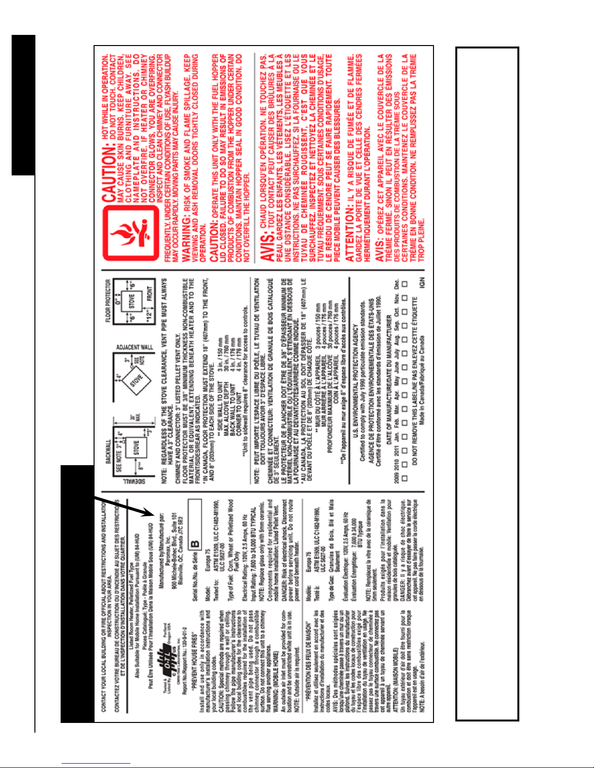
Certication label
Serial number of the unit
4
The security label is located on the back panel of the unit.
Here is a COPY of the certication label apposed on each unit. You can then examine the contents.
SAFETY PRECAUTIONS
01- DO NOT BURN GARBAGE OR FLAMMABLE FLUIDS SUCH AS GASOLINE, NAPHTHA OR ENGINE OIL AND
DO NOT USE CHEMICALS OR FLUIDS TO START THE FIRE
02- Do not store any combustibles near to the unit in operation. Minimum clearance from the unit and to store
combustibles are 4 feet or 1.21 meter. Store the combustible in a dry place
03- Do not use gasoline, gasoline-type lantern fuel, kerosene, charcoal lighter uid, or similar liquids to start or freshen
up a re in this unit. Keep all such liquids well away from the unit while it is in use.
04- Do not operate the unit if the burn pot overll with fuel. Turn off the stove and refer to the maintenance instruction.
05- Do not strike or slam shut the glass door, it may damage or crack the glass.
06- Do not use a substitute materials or components. Always replace by a Paromax part.
07- Do not operate the unit without burn pot ” tube” and the top ring or in invert position (upside down).
08- Do not burn treated material. Other materials such as wood preservatives, metal foils, coal, plastic, garbage,
sulphur, or oil may damage the catalyst.
09- Do not add combustible to the burn pot by hand when the unit is in operation.
10- Do not lay the ash pan on combustible oors when the ashes are hot.
11- It is very important to ensure that the unit is installed in a safe manner. Be aware of re prevention rules and laws in your
area. All applicable National and Local codes must be met and complied with. Notify your insurance company of this unit.
Do not use makeshift methods or compromise in the installation.
Safety instructions
12- We recommend a dealer authorized by Paromax to install your unit. If the unit is installed by an unauthorized installer,
Paromax will not be held responsible for any malfunction related to the chimney including a poor performance of the unit.
13- The electrical connection required with the unit consists of AC power inlet cord to plug into a standard wall outlet
(120 volts AC) with ground connection.
14- It is strongly recommended to install a smoke detector and an ABC type re extinguisher near the unit. Using a power
surge protector bar helps protect the electrical components of the unit and is highly recommended.
15- Your unit requires periodic maintenance and cleaning. Failure to maintain your stove may lead to a poor
performance, smoke spillage in your home or even a more dangerous situation.
16- To start your unit, always use a specied and approved re starter gel (gel approved for multi-fuel stove). Never
use a ammable liquid like gasoline, barbecue re starter or alcohol. Failure to comply with this may create a hazardous
situation and will void all warranties.
17- Never attempt to re-light your unit until the unit has fully cooled down. Never start your unit with a gel re starter when
the burner is still hot, it could cause severe burns. Wait until the unit and the burner are completely cold before you turn it
back on.
18- Manual feeding (primer) should only be used to initiate fuel supply to the burner when the hopper is empty. Do not use the
manual feed procedure to start your unit, it will cause smoke inside the combustion chamber.
19- Ensure that the ash pan door is securely closed at all times. Air pressure could ignite the fuel accumulated in the burn-pot
creating an overdraft condition in the combustion chamber altering the performance of the burn-pot.
20- The fuel supply will not operate if the main door or the hopper door are not closed.
21- The unit must be cold before any attempt to clean the main glasses. Do not use detergent containing abrasives to clean
the windows or any other parts of the stove. Use only recommended products found at your local hearth shop for this
type of cleaning.
22- Ashes must be disposed in a metal container with a tight lid and placed on a non-combustible surface well away from the
house. Wear gloves when handling or emptying the ashes as it can still be very hot.
23- Never use a vacuum cleaner to remove ashes from the stove or the burner or the ash pan, unless the stove is cold for
several hours.
5
Unit location
For optimum benet with your appliance, speak to an authorized Paromax Dealer concerning the unit location.
The location for your appliance can be a factor in how it will perform. Choose an interior location where the pellet
vent will not be affected by any external interference, ex; trees, bushes, walls or fencing (refer to “Vent Termination
Installation
Requirements” section at page 10). Install the unit according to recommendations made on “clearances” section at
page 10 or according to the safety label xed on the unit.
Always use a pellet vent double wall type PL with a inside diameter of 3” / 7.6 cm or 4” / 10.2 cm maximum. You
can pass the pellet vent system thru the wall behind the unit. Paromax recommend to use rigid pellet vent pipe up
thru the existing chimney.
Ensure that all clearances to combustibles are met as per the safety label and the diagrams on
“Clearances” section at page 9.
This appliance may need outside air if there is a negative pressure within the room. Make sure the outside air supply for the unit does not come from a garage, an attic or any restricted non-ventilated space.
The oor mat under the stove must be of non-combustible material, i.e. cement, ceramics, etc... and must extend
6” or 15.2 cm for the sides and front. Refer to the diagrams on “Clearances” section at page 9.
Requirement: Avoid any PL pellet vent quick connection (twist lock) in the attic or roof space, closet or similar concealed space, oor or ceiling. Do not use different brand or models of vent pipe on the same vent pipe installation.
WARNING: DO NOT INSTALL A FLUE DAMPER IN THE EXHAUST VENTING SYSTEM
OF THIS UNIT. DO NOT CONNECT THIS UNIT TO A CHIMNEY FLUE SERVICING ANOTHER APPLIANCE. DO NOT CONNECT TO ANY DISTRIBUTION DUCT OR SYSTEM.
Pellet vent size (PL)
IMPORTANT: Always use a double wall 3” / 7.6 cm or 4” / 10.2 cm PL type pellet vent approved for venting wood
pellets fuel or agriculture fuel. A tight seal (silicone or aluminum tape) is recommended on each section of the
pellet vent to prevent smoke leakage and odors. The pipe connecting to the unit and the outer wall joints located
between the pipes also need to be sealed with high temperature silicone or aluminum tape. The maximum pellet
vent height is 35 feet or 10.6 meter. Use a wall thimble for ammable wall or collar for cement wall. Seal the exte-
rior pellet vent with silicone to create a vapor barrier.
It is not recommended to seal the inner walls joints already containing a pre-installed silicone or rubber
sealant by the manufacturer of the pellet vent. Do not use a perforated outer wall pellet vent ue channel-
ing fresh air to the burner.
WARNING: DO NOT INSTALL IN SLEEPING ROOM
CAUTION: THE STRUCTURAL INTEGRITY OF THE MANUFACTURED
HOME FLOOR, WALL AND CEILING/ROOF MUST BE MAINTAINED
6
Chimney types (continued)
Since this is a multi-fuel unit, it is recommended to choose an approved venting system. If you choose wood pellets, a double wall 3” or 7.6 cm stainless steel pipes are recommended. For agriculture fuel, it is recommended to
use double wall PL type 3” or 7.6 cm stainless with higher quality durability. Refer to the vent pipe manufacturer for
more details.
Do not use a non-approved pipe for your vent system. i.e., Dryer vent, “B” vent for gas vent, PVC/plastic pipe or
single wall chimney system.
Please note that the length of a horizontal venting system shall not exceed 24” or 61 cm.
Always vent to the outside atmosphere and never into enclosed spaces, i.e. garage, car port etc. Venting systems
can generate heat and smoke.
WARNING: HOT UNIT WHILE IN OPERATION.
KEEP CHILDREN, CLOTHING AND FURNITURE AWAY.
ANY CONTACT MAY CAUSE SKIN BURNS
Installation
Mobile home installation
Use PL type chimney for immediate evacuation outside the mobile home. Refer to the chimney diagram for proper
exhaust installation. The space heater is to be connected to a factory-built chimney conforming to CAN/ULC-S629,
standard for 650 degrees F or 343 degrees C. For proper clearances, remove outside sections of the chimney
when displacing the mobile home. Outside air inlet must be provided for combustion and be unrestricted while unit
is in use. Refer to outside inlet installation on page 8. The unit must be securely fastened to the oor by using one
bolt in the front and two bolts in the back of the unit.
Recommendation: Chimney installation in a windy area must rise above the roof.
It’s normal for ice build-up around the cap during cold or
windy days.
High elevation
High altitude reduces air capacity to the burner. To help increase the air speed, a vertical chimney above the roof is
recommended to create a natural air ow. Refer to the chimneys diagrams on page 11 and 12.
Negative pressure in the house or starvation air
The use of a bathroom fan, dryer, kitchen hood fan, etc, can create negative pressure, especially in new air tight
homes. Combined, these fans consume three times more air than the combustion fan on the unit, and may create
a signicant drop of pressure therefore a lack of air to the burner that may cause a re extinguishing. Paromax
suggest you take a gauge reading before, during and after the use of your appliances and/or fans to check the
pressure variations. If the pressure changes, Paromax recommends installing an outside air intake. Refer to fresh
air installation for more information on page 8.
7
Outside inlet Installation (FA01 kit)
Use a coupling (pipe thread) to increase 1” or 2.5 cm to 2” or 5 cm, install a one way valve, maximum length is 5
feet or 1.5 meter. For more than 5 feet or 1.5 m, increase to 2.5” or 6.3 cm diameter for a maximum of 10 feet or 3
m total. Install cap with a grill to prevent rodent’s intrusion.
Note: Seal outside pipe joints and wall outlet with silicone to prevent water from entering. To view air inlet location,
Installation
refer to page 9 (width picture).
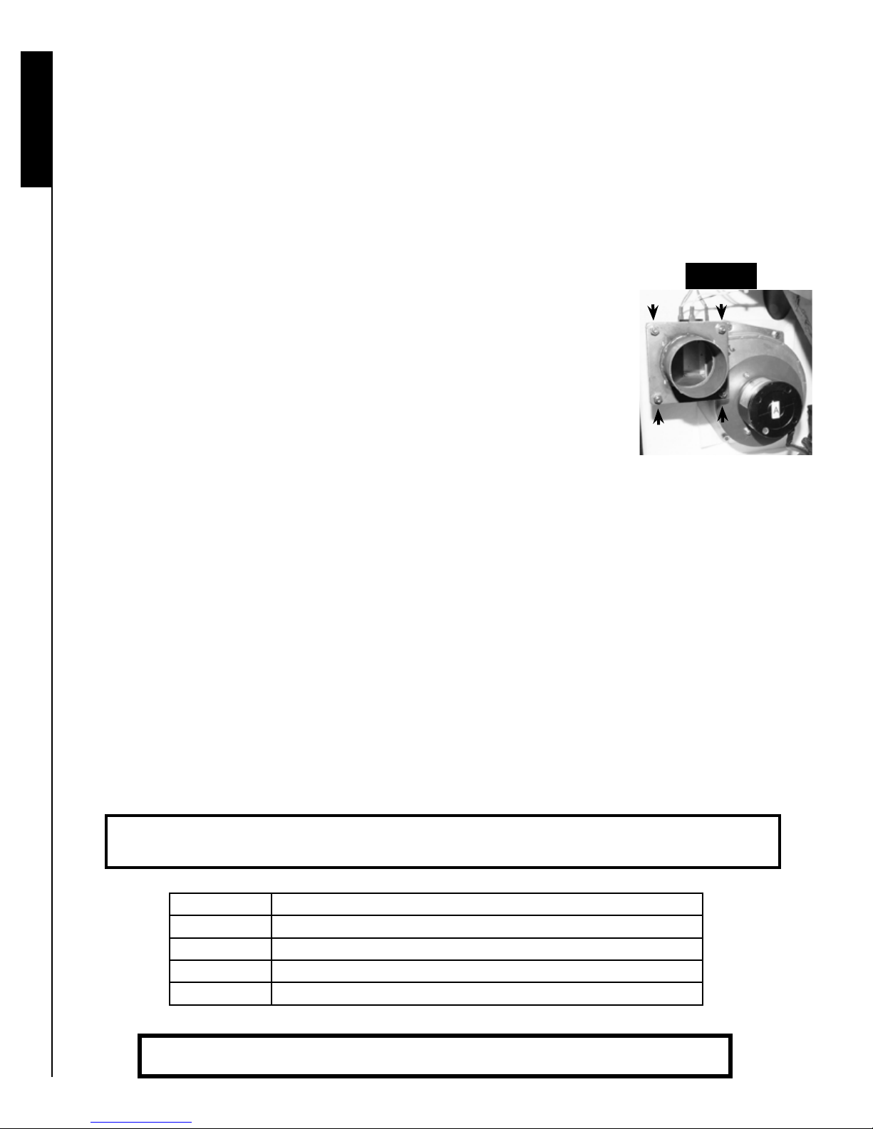
Pressure regulator
Image 1
Natural draft may create a malfunction due to increased pressure. If necessary, obtain
a plate restriction from your dealer.
To install the plate restriction, refer to the image 1 to view the air outlet. There are 4
nuts and bolts to be removed from the air outlet by using a 7/16 or 11 mm wrench
socket. Install the pressure regulator on the combustion fan air outlet; take care to replace the white seals on each side of the pressure plate. Replace the bolts, washers
and nuts on the air outlet and tighten the bolts for a hermetic pressure regulator.
Battery supplied with the unit
This battery will allow uninterrupted operation of your unit in case of power failure. Please note that this system
does not replace the standard electrical power of 120 volt AC of the unit. This is a battery backup feature. When
fully charged, it can last 4 hours or less depending on heat level setting (1-5) used. It is recommended to always
leave the battery connected. The battery will be recharged when the power comes back.
For an extended performance, we suggest purchasing a 12 volt car battery for a longer use.
If a power outage occurs for more than 3 seconds and there is no battery connected, the fans will stop and there is
a risk of smoke. When electricity is restored, the control panel will display the error code E3. If the unit is still hot,
the fans will start to cool down the unit. In case of interruption of less than 3 seconds, the unit could continue to
operate normally.
Option: To use the unit on 12 volt continuously as your main power, we recommend to by-pass the power inverter.
Disconnect inverter the black wire identied on COM and the red wire identied on V1 on the power inverter and
then connect these wires directly to the 12 volt DC source. The Warranty does not cover any polarity inversion
that may damage the control panel (see picture 36 on page 32).
Notice: Your battery is provided with an insulation to prevent ground contact.
To avoid any discharge, never sit the battery directly on the cement oor.
Step Battery connection order to follow
1 Connect the red clip to the positive battery terminal +
2 Connect the black clip to the negative battery terminal -
3 Connect the battery red wire to the unit red wire.
4 Connect the battery black wire to the unit black wire.
8
WARNING: Children should be kept away from the hot unit.
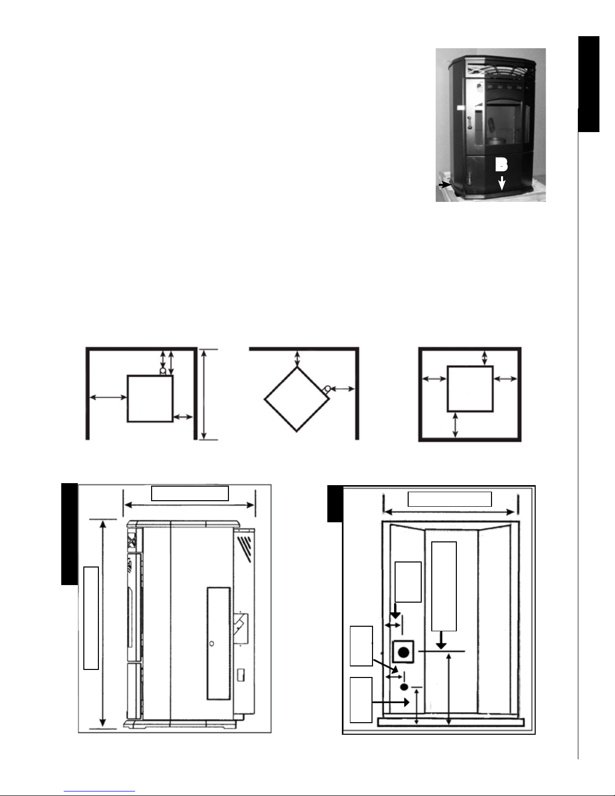
Leveling your unit
It is essential to level your unit for a stable fuel bed. First put a level on
the side of the base (letter A) and use metal “spacer” to adjust the lowest
side. And then, level the front by placing the level on the front of the base
(B). When burning agriculture fuel, Paromax suggests increasing the height
of the front of the unit by 1/4” to 3/8” or 6 to 10 mm. This modication helps
to reduce ash accumulation in the front of the burner.
Installation
B
Thermostat installation for the EUROPA
A
For thermostat use, purchase a thermostat supply by battery (AA or AAA batteries or 9 volt) or a mercury thermostat or wireless thermostat. Connect the thermostat to purple wires that are located near the control panel inside
the unit. See thermostat operation mode on page 21
Clearance of the EUROPA
NON-COMBUSTIBLE
BACKWALL
SEE
NOTE
8”-
20 CM
3”-
7.6 CM
UNIT
6”-
15
CM
3”-
7.6 CM
38”-
96.5 CM
MAX
ADJACENT WALL
4”-
10 CM
3”-
7.6 CM
UNIT
SEE
NOTE
FLOOR PROTECTOR
6”- 15 CM
*6”-
15.2
CM
UNIT
*6”- 15.2 CM
*6”-
15.2
CM
FRONT
25 1/4” / 64 cm
Height and Depth
40 1/2” / 102.9 cm
Width
5” or
10 5/8” or
12.7 cm
27 cm
26 1/2” / 67.3 cm
14.6 cm
5 3/4” or
” or 49.2 cm
Centerline axe
19 3/8
9
IT IS RECOMMENDED THAT YOUR PELLET STOVE BE INSTALLED
BY A PAROMAX AUTHORIZED DEALER/INSTALLER.
CLEARANCE TABLE: Use in conjunction with diagram on page 11 for allowable exterior vent
locations for both horizontal and vertical terminations. Clearances may only be reduced by means
Installation
approved by a regulatory authority.
Minimum Description
A
A
B
C
D
E
F
G
H
24” / 61 cm
12” / 30.5 cm
48” / 122 cm
12” / 30.5 cm
24” / 61 cm
24” / 61 cm
12” / 30.5 cm
12” / 30.5 cm
36” / 91.5 cm
Above lawns, top of plants, wood or any other combustible materials.
Above non-combustible surface such as cement and gravel.
From beside/below any door or window that may be opened.
From above any door or window that may be opened.
To any adjacent building, fences and protruding parts of the structure.
Below any eaves or roof overhang.
To outside corner.
To inside corner, combustible wall (vertical & horizontal terminations).
To each side of center line extended above natural gas or propane meter/reg-
ulator assembly or mechanical vent within a height of 14’ 1/2” or 4.5 m above
the meter/regulator assembly.
I
36” / 91.5 cm
J
12” / 30.5 cm
From any forced air intake of other appliance.
Clearance to non-mechanical air supply inlet to building or combustion air
inlet to any appliance.
K
24” / 61cm
Clearance above roof line for vertical terminations.
NOTES :
1. Do not terminate the vent in any enclosed or semi-enclosed areas that can build up a
concentration of smoke.
2. Vent surfaces can become extremely hot. Keep children away from such areas. Non-combustible
shielding or guards may be required.
3. Termination must exhaust above sea level and the inlet elevation. It is recommended to have a
short vertical run which will help in the event of total power failure.
4. If the unit is incorrectly vented or the air to fuel mixture is out of balance, a slight discoloration of
the exterior of the house might occur. Since these factors are beyond our control we offer no
guarantee against such incidents.
5. When installing into an existing masonry chimney, you will probably need a short horizontal
section to clear the lintel and allow the hopper lid to open.
6. Vent terminations shall not be recessed into walls or siding.
7. A vent shall not terminate directly above a sidewalk or paved driveway which is located between
two single family dwellings and serves both dwellings.
8. If the vent termination is children accessible, a certied guard shall be installed as specied in
CGA B149 installation Code in Canada. Note: Local codes or regulations may require different
clearances.
10

Minimum clearances table for a wall installation
INSTALL VENT AT CLEARANCES SPECIFIED BY THE VENT MANUFACTURER
Refer to the norm CAN/CSA-B365-01 before installing the vent.
Clearances table
12” or
30.5 cm
MIN.
Minimum
distance
3” or 7.6 cm
Stove
12” or
30.5 cm
MIN.
3” or 7.6 cm
Stove
Chimney types
Minimum
distance
Equivalent Vent length (EVL)
Venting your unit is crucial for optimum operation. There are ve different installation examples recommended by
Paromax.
The unit uses the combustion fan to move air from the exhaust to the chimney. (Next on page 12)
11
 Loading...