

PARMAIR EXIUS JrS, JrV Technical Specifications And Implementation Manual
JrS and JrV
TECHNICAL SPECIFICATIONS AND
IMPLEMENTATION GUIDE

2
1. GENERAL
Healthy indoor air quality depends on efficient ventilation. The types of work people do at home
and construction methods have changed a lot over recent decades.
Today’s well-insulated homes need controlled ventilation, which increases the comfort and
congeniality of living conditions. Adequate ventilation expels harmful gases and odors arising
from the structure, plumbing fixtures, interior finishes and cooking. Good construction methods
and continuous and adequate ventilation are necessary in order to prevent damp penetration.
Waste air needs to be continuously extracted from the kitchen, bathroom, dressing room, sauna
and shower areas. Ventilation should be designed so that the total air extracted is normally equal
to half the volume of air in a dwelling (half of the air in the house needs replacing every hour,
40% by ventilation and 10% by leakage). Fresh air is blown into bedrooms and living areas and
into the sauna and adjoining room with fireplace.
Ventilation consumes approximately 30% of a dwelling’s energy. The Eximus Jr Unit allows the
heat from extracted air to be transferred to incoming fresh air. By means of a ventilation system
equipped with heat recovery, you can save up to 70% of the cost of operating a system that
simply extracts air.
For ventilation systems to meet the sound level requirements published at the start of 2000,
ventilation units must not directly adjoin living areas. When the unit is fixed to a wall, there
should be no vibration transferred to the structure.
The dwelling’s ventilation system should be carefully planned and built according to plan.
PARMAIR EXIMUS JrS and JrV
2. TECHNICAL SPECIFICATIONS
Unit dimensions Height 600 mm
Width 585 mm
Depth 430 mm
Voltage 230V, 50Hz
Fans (2) DC fan 120W
Reheating 2 x 0–600W using electricity, electronic
regulation as necessary, model Eximus JrS
800W using domestic hot water, model Eximus JrV
Preheating 0–700W electronic regulation as necessary
Condensation water connector CU pipe, external ∅15 mm in rear corner
Maximum air volume 140l/s (50Pa)
Temperature efficiency ratio Approx. 60% (q
=60dm3/s)
V
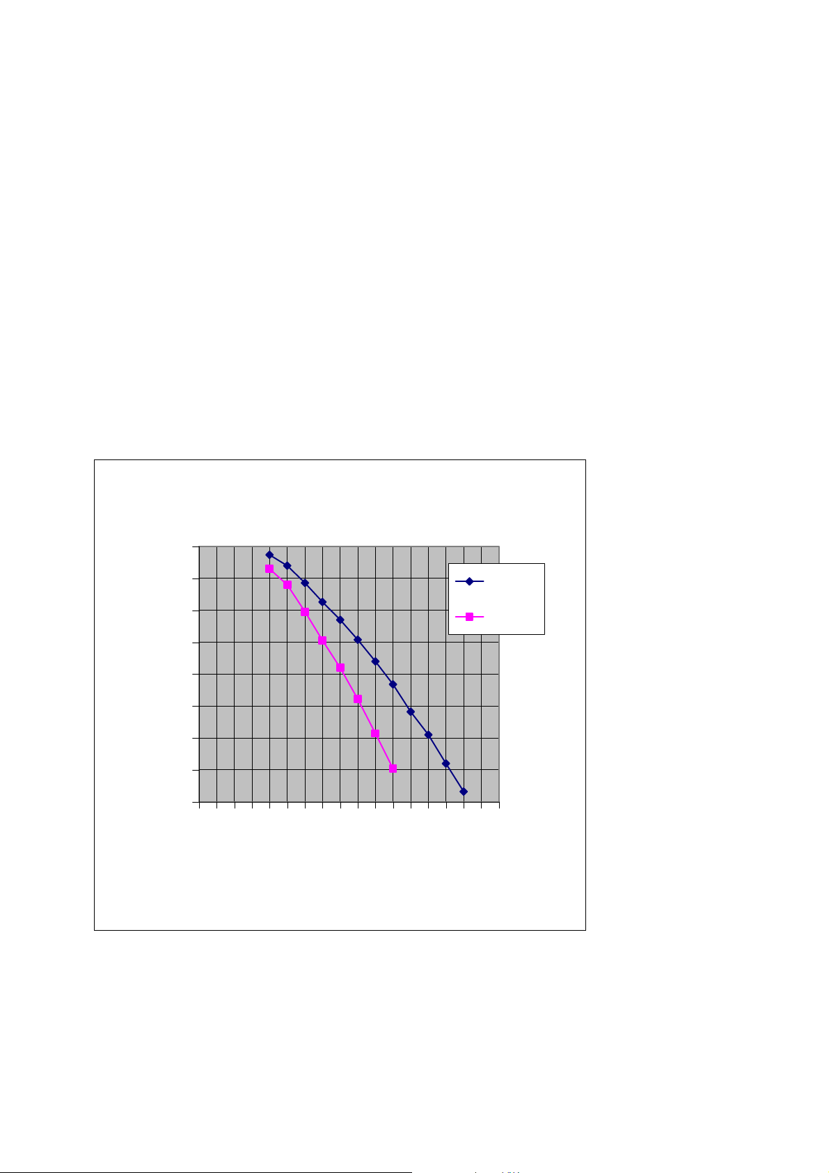
3. UNIT AIR EXHANGE VOLUME FLOW
3
Eximus Jr air exchange volume flow rate
400
350
300
250
200
150
100
Static pressure [Pa]
50
0
0
20
40
60
80
100
120
Air volume flow rate (l/s)
140
Extract
Supply
160
Diagram 1. Air exchange volume flow rate (with EU4 intake/extract filters)
PARMAIR EXIMUS JrS and JrV

4
4. OPERATING PRINCIPLES OF THE EXIMUS UNITS
The Parmair Eximus Jr Units are equipped with heat exchangers consisting of thin aluminum
plates. Extracted air and incoming air are separately fed into alternate slots between the plates.
Heat from the extracted air is transferred to the incoming fresh air through the plates without
mixing the airflows.
Extracted air is drawn from the house through ventilation ducts into the unit where the air is
filtered, and passes from the heat exchanger into an exhaust duct and then outside.
Incoming air is drawn into the ventilation unit from outside through another duct and is finely
filtered (Filter EU7) before heat transfer occurs, after which it passes through incoming air ducts
into the various rooms in the house.
When temperatures fall below zero, moisture condensing from extracted air collects on the
surface of the heat exchanger. Because of this, the heat transfer parts of Parmair Eximus Jr Units
are equipped with an electronically controlled antifreeze system that prevents the heat exchanger
from freezing under any circumstances, thus maintaining the ventilation in balance.
The unit has a condensation pipe to remove water condensed from the extracted air. The water
runs to a floor drain through a hose or pipe.
When temperatures fall well below zero, incoming air is still cold despite the heat exchanger.
For this reason, the unit comes with a reheating element. The desired temperature of incoming
air can be set from the control panel. The electronically controlled heating element helps the unit
maintain the desired temperature.
PARMAIR EXIMUS JrS and JrV
V
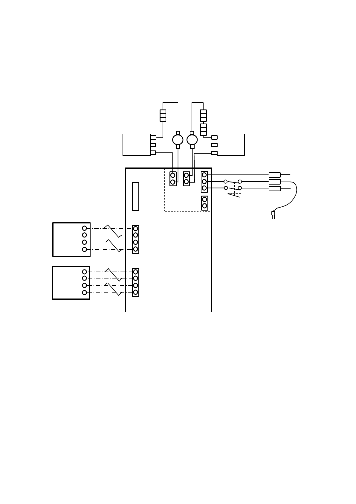
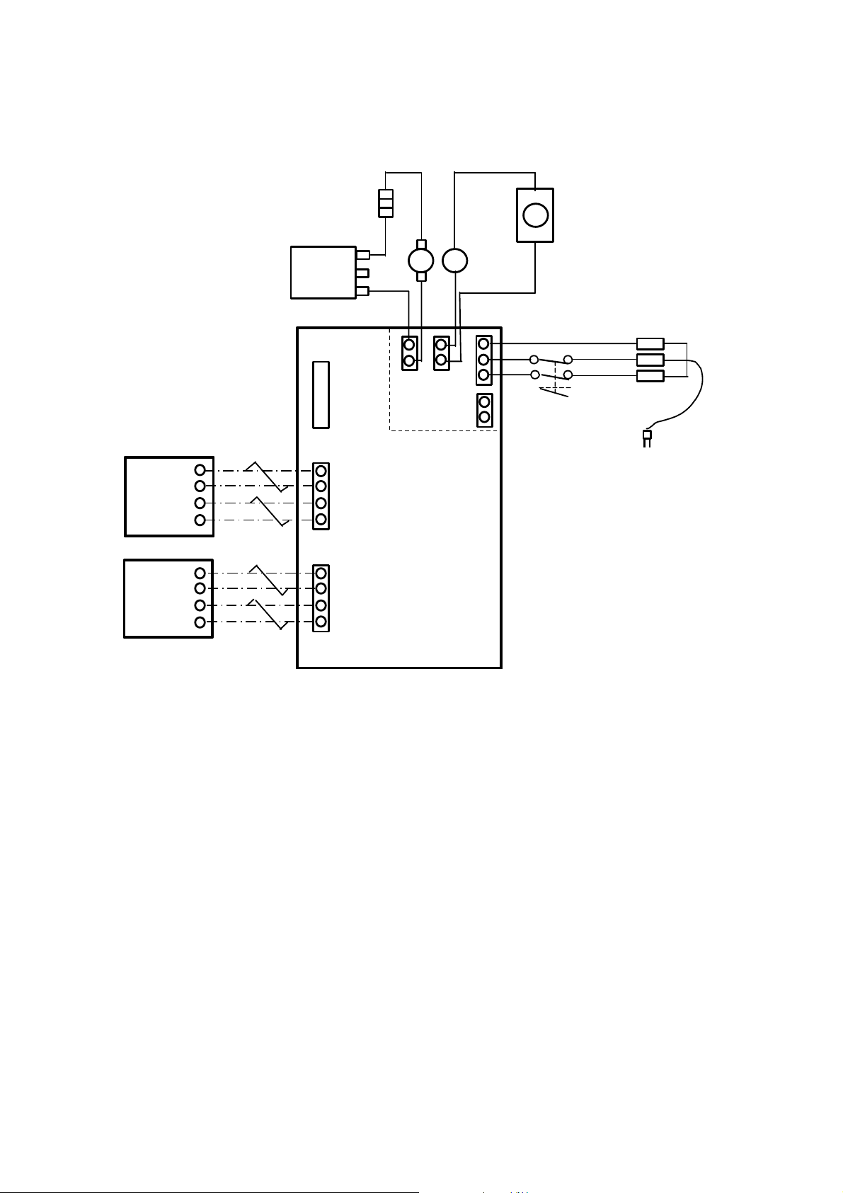
5. ELECTRICAL CONNECTION DIAGRAM
The connections are according to the following diagrams
(Diagram 2 for the JrS Unit and Diagram 3 for the JrV Unit).
Parmair Eximus JrS
5
control
Remote
Remote
control
Preheating 700 W/230V
4 x 0,5
12
34
34
12
4 x 0,5
shield
Thermal
Extra
J3
1
2
J2
J1
C2 1
43
4
321
T50 T50
J13
J11
230
Reheating 2x600 W/115V
Thermal
shield
C21
J12J14
Master switch
Diagram 2. Electrical connection diagram, the JrS Unit
PARMAIR EXIMUS JrS and JrV
V
Parmair Eximus JrV
6
Remote
control
Remote
control
Preheating 700W/230V
12
34
34
12
shield
Thermal
J3
J2
C2 1
2
43 1321
4
Extra
T50
J13
230
M
J11
J12
J14
Reheating
+
Master switch
J1
Diagram 3. Electrical connection diagram, the JrV Unit
PARMAIR EXIMUS JrS and JrV

The Parmair Eximus Jr Units always come with a control unit. The control unit is attached to the
control panel of the unit, but it can also be detached and mounted on a switch case.
Another control unit (optional) can also be connected to the unit. The separate control unit will
function alongside the standard fixed control unit. The three fan speeds are set steplessly during
installation, and may be reconfigured at a later time (see the Implementation Guide).
The Parmair Eximus Jr Units can also be equipped with a control unit based on moisture (%RH),
carbon dioxide (CO
automatically switches to boosted ventilation when it receives an outside control voltage from
one of the mentioned sources; after the need for the boost is over, it returns to basic mode.
The ventilation unit should always at least be switched on to the lowest setting (min). This
will ensure that indoor air stays healthy and that the disadvantages of humidity and damage from
freezing are avoided.
) or other outside control device such us a weekly timer. The unit
2
7
6. INSTALLING THE UNIT
Parmair Eximus Jr Units are intended for installation in warm indoor areas (above +5° C). The
unit is attached to the wall by fixing points along the upper and lower edges and on the rear
panel of the unit. The unit should be tilted slightly backwards to allow the condensed water to
run out. A separate electric supply from distribution board is recommended for the unit.
7. CONNECTING THE CONDENSATION WATER PIPE
The condensation water pipe is laid separately to a floor drain, a drainpipe or a loose container.
To avoid airlocks, add water to seal when the unit has been installed and whenever maintenance
is performed on the filter.
THE CONDENSATION UNIT OF THE EXIMUS Jr UNIT IS ON THE BOTTOM OF THE
VENTILATION UNIT ON THE LEFT OR RIGHT SIDE, DEPENDING ON WHETHER IT IS
LEFT- OR RIGHT-HANDED.
PARMAIR EXIMUS JrS and JrV
 Loading...