

Page 1
Ultra Micro
T-28 Trojan RTF/BNF
RTF
Instruction Manual
Bedienungsanleitung
Manuel d’utilisation
Manuale di Istruzioni
Page 2

2
Page 3
3
Safety Precautions and Warnings
As the user of this product, you are solely
responsible for operating in a manner that
does not endanger yourself and others
or result in damage to the product or the
property of others.
This model is controlled by a radio signal
subject to interference from many sources
outside your control. This interference can
cause momentary loss of control so it is
advisable to always keep a safe distance
in all directions around your model, as this
margin will help avoid collisions or injury.
Age Recommendation: 14 years or
over. This is not a toy. This product is not
intended for use by children without direct
adult supervision.
Never operate your model with low •
transmitter batteries.
Always operate your model in open •
spaces away from full-size vehicles,
tra c and people.
Carefully follow the directions and •
warnings for this and any optional
support equipment (chargers,
rechargeable battery packs, etc.)
you use.
Keep all chemicals, small parts and •
anything electrical out of the reach
of children.
Moisture causes damage to electronics. •
Avoid water exposure to all equipment
not speci cally designed and protected
for this purpose.
Never lick or place any portion of your •
model in your mouth as it could cause
serious injury or even death.
WARNING: Read the ENTIRE instruction manual to become familiar with the features
of the product before operating. Failure to operate the product correctly can result in
damage to the product, personal property and cause serious injury.
This is a sophisticated hobby product and NOT a toy. It must be operated with caution and
common sense and requires some basic mechanical ability. Failure to operate this Product
in a safe and responsible manner could result in injury or damage to the product or other
property. This product is not intended for use by children without direct adult supervision.
Do not attempt disassembly, use with incompatible components or augment product in
any way without the approval of Horizon Hobby, Inc. This manual contains instructions for
safety, operation and maintenance. It is essential to read and follow all the instructions and
warnings in the manual, prior to assembly, setup or use, in order to operate correctly and
avoid damage or serious injury.
NOTICE
All instructions, warranties and other collateral documents are subject to change at the
sole discretion of Horizon Hobby, Inc. For up-to-date product literature, visit http://www.
horizonhobby.com and click on the support tab for this product.
Meaning of Special Language:
The following terms are used throughout the product literature to indicate various levels of
potential harm when operating this product:
NOTICE: Procedures, which if not properly followed, create a possibility of physical property
damage AND little or no possibility of injury.
CAUTION: Procedures, which if not properly followed, create the probability of physical
property damage AND a possibility of serious injury.
WARNING: Procedures, which if not properly followed, create the probability of property
damage, collateral damage, and serious injury OR create a high probability of
super cial injury.
EN
Page 4

4
This exciting Ultra Micro Series edition of ParkZone’s wildly popular T-28 is a must-have for
any intermediate to experienced pilot. Like the original, it has plenty of performance for
sport aerobatics but remains a joy to y at slower speeds if you want to throttle back and
shoot touch and gos. And, like the original, it boasts remarkably scale lines and a great
looking U.S. Navy trim scheme. Best of all, this one is small enough to y in your backyard.
To register your product online, go to http://www.parkzone.com
Safety Precautions and Warnings ................. 3
Introduction ......................................................... 4
First Flight Preparation ..................................... 4
Maintenance Tips ............................................... 4
Battery Warnings ................................................ 5
Low Voltage Cuto (LVC) ................................. 5
Charging the Battery .......................................... 6
Transmitter and Receiver Binding .................7
Installing Transmitter Batteries ....................... 7
Transmitter Controls .......................................... 8
Digital Trims .......................................................... 8
Dual Rate Function .............................................8
Control Direction Test ........................................8
Reverse Controls ..................................................9
Control Centering..............................................10
Installing Landing Gear ...................................10
Receiver Control Unit .......................................11
Arming ..................................................................11
Motor Control Test ............................................11
Adjusting Center of Gravity ...........................11
Propeller and Propeller Shaft Maint. ..........12
Flying Tips ............................................................13
Repairs ...................................................................13
Re-binding Transmitter ...................................13
Troubleshooting Guide ...................................14
Replacement Parts and Optional Parts .....15
Warranty and Service .......................................15
Contact Information .........................................16
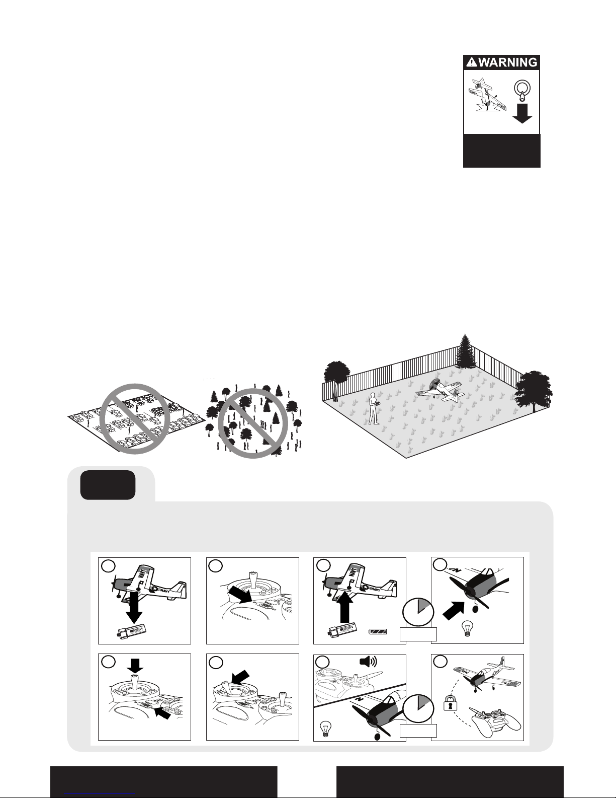
First Flight Preparation
Remove and inspect contents•
Begin charging the ight battery•
Install landing gear•
Install batteries into battery charger•
Install batteries into the included •
transmitter (RTF ONLY)
Install fully charged battery•
Bind the receiver to a transmitter •
(BNF ONLY)
Perform the Control Direction Test with •
the transmitter
Adjust ight controls and transmitter•
Adjust battery for center of gravity (CG) •
Perform a radio system Range Check•
Find a safe and open area•
Plan ight for ying eld conditions•
Maintenance After Flying
Disconnect ight battery from ESC •
(Required for Safety)
Turn o transmitter•
Remove ight battery from aircraft•
Recharge ight battery•
Repair or replace all damaged parts•
Store ight battery apart from aircraft •
and monitor the battery charge
Make note of ight conditions and ight •
plan results, planning for future ights
Table of Contents
T-28 Speci cations
Wingspan
Length
Weight
16.8 in (426mm)
13.5 in (343mm)
1.30 oz (38 g)
T-28 Features
Bind-N-Fly
Version
Ready to Fly
Version
Onboard Electronics
Spektrum AR6400
Receiver/Servos/ESC
Installed Installed
Battery
120mAh 3.7V 14C
Li-Po
Included Included
Charger
1S 3.7V Li-Po Battery
Charger
Included Included
Transmitter
DSM2 aircraft
transmitter
Sold
Separately
Included
EN
Page 5

5
The Battery Charger (PKZ3240) included with
the T-28 BNF has been designed to safely
charge the Li-Po battery. You must read the
following safety instructions and warnings
before handling, charging or using the Li-Po
battery.
CAUTION: All instructions and warnings must
be followed exactly. Mishandling of Li-Po
batteries can result in a re, personal injury,
and/or property damage.
By handling, charging or using the •
included Li-Po battery you assume all
risks associated with lithium batteries.
If you do not agree with these conditions,
return your complete T-28 model in new,
unused condition to the place of
purchase immediately.
DO NOT USE A Ni-Cd OR Ni-MH •
CHARGER. Failure to charge the battery
with a compatible charger may cause re
resulting in personal injury and/or
property damage.
If at any time during the charge process •
the battery begins to balloon or swell,
discontinue charging or discharging
immediately. Quickly and safely
disconnect the battery, then place it in
a safe area away from ammable
materials to observe it for at least 15
minutes. Continuing to charge or
discharge a battery that has begun to
balloon or swell can result in a re.
Store the battery at room temperature in •
a dry area for best results.
When transporting or temporarily storing •
the battery the temperature range should
be from 40–120º F. Do not store battery
or model in a car or direct sunlight.
If stored in a hot car, the battery can be
damaged or even catch re.
Li-Po cells should not be discharged to •
below 3V each under load.
Battery Warnings
Low Voltage Cuto (LVC)
The T-28 receiver features a soft low voltage
cuto (LVC) that occurs when the battery
reaches 3V per cell under load. When the soft
cuto occurs, the electronic speed control
(ESC) and receiver reduce power to the motor
(regardless of the power level set with the
throttle stick). This prevents the voltage of the
battery from dropping below 3V per cell.
While it is possible to continue ying the
aircraft after the soft LVC occurs, this is NOT
recommended. Battery discharge after LVC
will damage the Li-Po battery, resulting in
less power and shorter ight duration during
subsequent ights, or complete failure of
the battery.
Discharging the battery after low voltage
cuto may result in loss of control. Battery
power may drop below the receiver’s
minimum operating voltage so ight controls
do not respond to the transmitter.
Stay aware of the power level of the battery/
aircraft throughout the ight, and when the
aircraft requires more throttle than typical,
immediately land the T-28.
Note: Battery performance is reduced in
cooler temperatures.
CAUTION: ALWAYS disconnect the battery
from the aircraft to prevent trickle discharge
of the battery. These batteries require
regular maintenance to keep them at a
usable charge level.
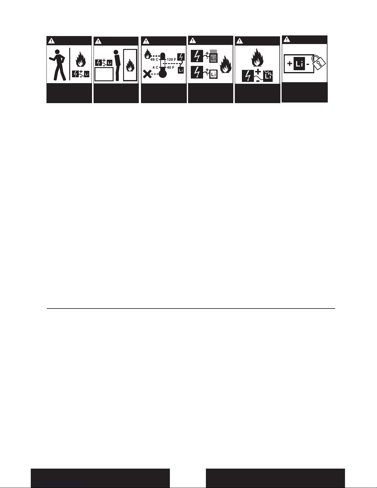
Never leave
charging Batteries
unattended.
Always charge
Batteries away from
flammable materials.
Never charge
Batteries outside safe
temperature range.
Never charge
Batteries outside
recommended levels.
Store
Batteries
safely.
Never charge
damaged Batteries.
EN
Page 6

6
Charging the Battery
The Battery Charging Process
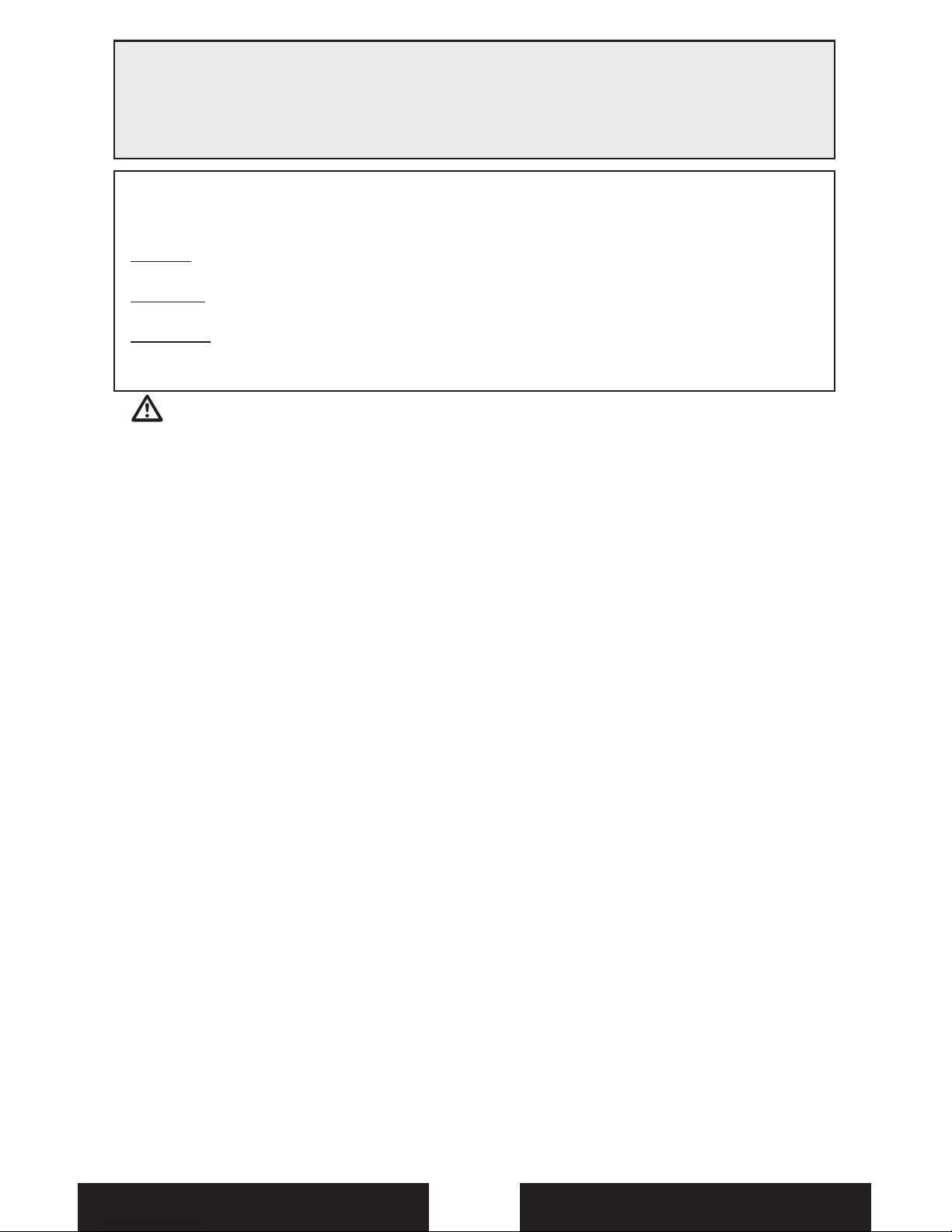
1. Charge only batteries that are cool to the touch and are not damaged. Look at the battery to make
sure it is not damaged e.g., swollen, bent, broken or punctured.
2. Remove the cover on the bottom of the charger and install four of the included AA batteries, noting
proper polarity. Replace the cover after the AA batteries are installed.
3. Slide the battery into the slot on the charger. The end cap of the battery is specifically designed to
allow the battery to fit into the slot one way (usually with the label on the battery facing outward)
to prevent reverse polarity connection. However, check for proper alignment and polarity before
proceeding to the next step.
4. Gently press the battery and its connector into the charge jack/connector located at the bottom of
the slot in the charger.
5. When you make the connection successfully, the LED on the charger turns solid red, indicating
charging has begun.
6. Charging a fully discharged (not over-discharged) 120mAh battery takes approximately 30–40
minutes. As the battery nears full charge, the LED begins to blink.
7. When the battery is fully charged, the LED blinks approximately every 20 seconds or goes out
entirely.
Note: If the LED stays on when the LiPo is removed, the AA batteries in the charger are low.
8. Always unplug the battery from the charger immediately upon completion of charging.
CAUTION: Overcharging a battery can cause a fire.
WARNING: Failure to use the proper charger for a Li-Po battery can result in serious damage,
and if left charging long enough, will cause a re. ALWAYS use caution when charging
Li-Po batteries.
WARNING: Selecting a charge rate higher than 1x (one times) the battery capacity on a
variable rate charger may cause a re.
Your T-28 comes with 1S 3.7V Li-Po Battery
Charger and 1S Li-Po battery. It is important
that you only charge with the included
charger, or the E- ite® Celectra™ 4-port
Charger (EFLC1004). Refer to page 4. It is
recommended to charge the battery pack
while you are assembling the aircraft. The
ight battery will be required to con rm
proper aircraft operation in future steps.
EN
Page 7
7
RTF
®
Binding is the process of programming the receiver of the control unit to recognize the GUID
(Globally Unique Identi er) code of a single speci c transmitter. You need to ‘bind’ your chosen
Spektrum DSM2 technology equipped aircraft transmitter to the receiver for proper operation.
To bind or re-bind your T-28 to your chosen transmitter please follow the directions below:
Your T-28 RTF transmitter comes pre-bound to the aircraft, so binding should not be necessary.
All that is needed to begin ying is installation of fully charged batteries in the aircraft
and transmitter.
Installing Transmitter Battery
3
4
1
2
6
5
7
The T-28 requires a DSM2 transmitter. The list below is Spektrum™ or JR® DSM2-equipped
transmitters that can bind to the T-28. (If your transmitter is not listed, please contact Horizon Hobby):
• E- ite MLP4DSM • E- ite LP5DSM • ParkZone Vapor® Transmitter • JR X9503
• ParkZone Ember® 2 Transmitter • JR 12X 2.4 • JR X9303 2.4 • HP6DSM
• Spektrum DX5e • Spektrum DX6i • Spektrum DX7/DX7se
9
Binding Procedure Reference Table
1. Refer to your transmitter’s unique instructions for binding to a
receiver.
2. Make sure the ight battery is disconnected from the airplane.
3. Power o the transmitter.
4. Connect the ight battery in the aircraft. The receiver LED will
begin to ash. (Typically after 5 seconds).
5. Put your transmitter into bind mode. If using the MLP4DSM
transmitter, push the left control stick vertically into the case
until it clicks, while powering on the transmitter.
6. Make sure transmitter controls are neutral and throttle is in
low position.
Prior to each ight, power on your transmitter and wait about 5 seconds before you plug the
ight battery into the receiver. This allows time for the transmitter to scan and secure two
open frequencies. If you plug the ight battery in too quickly and miss the link, the receiver
may inadvertently enter bind mode. If this occurs leave the transmitter on, then disconnect and
reconnect the ight battery. Avoid binding multiple transmitters and receivers simultaneously,
binding near large metal objects (furniture, vehicles, etc.), and binding with the transmitter too
near the aircraft. Please bind the transmitter at least 50 cm from aircraft.
Transmitter and Receiver Binding
Additional Binding Information
List is complete as of this printing. Additional compatible transmitters may be available.
EN
Page 8
8
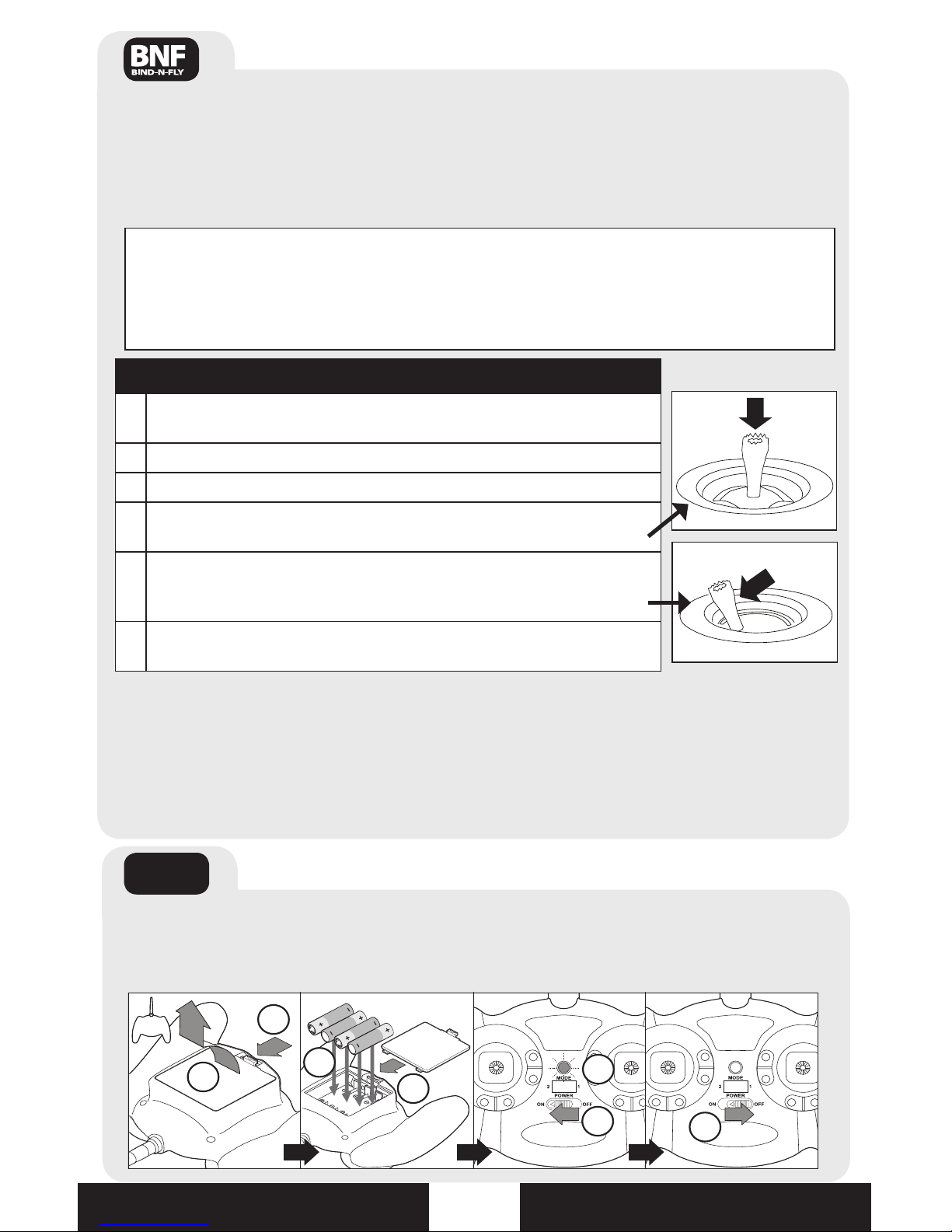
Elevator
Trim
Rudder
Trim
Throttle
Trim
Aileron
Trim
Throttle/Aileron
Function
Elevator/Rudder
Function
Mode 1
Throttle
Trim
Elevator
Trim
Aileron
Trim
Elevator/Aileron
Function
Throttle/Rudder
Function
Mode 2
Transmitter Control
Digital Trims
The ParkZone® 4-channel 2.4GHz DSM2 transmitter features digital trim buttons on all controls
to make ne adjustments. Before the rst ight, center the control surfaces mechanically (see
Control Centering, page 9). The digital trims are used to ne–tune the model’s ight path when
in ight.
Note: When pressed down, trim buttons make a sound that increases or decreases in pitch at
each pressing. The middle or neutral trim position is heard as a middle tone in the pitch range of
the sounds. The end of the control range is sounded by a series of beeps.
Dual Rate Function
RTF
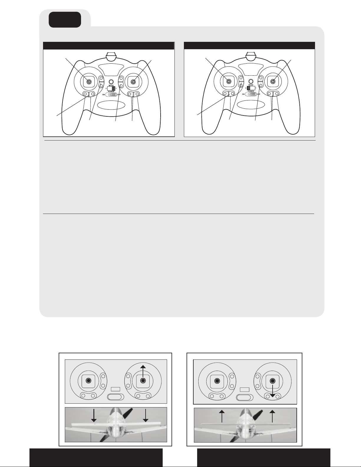
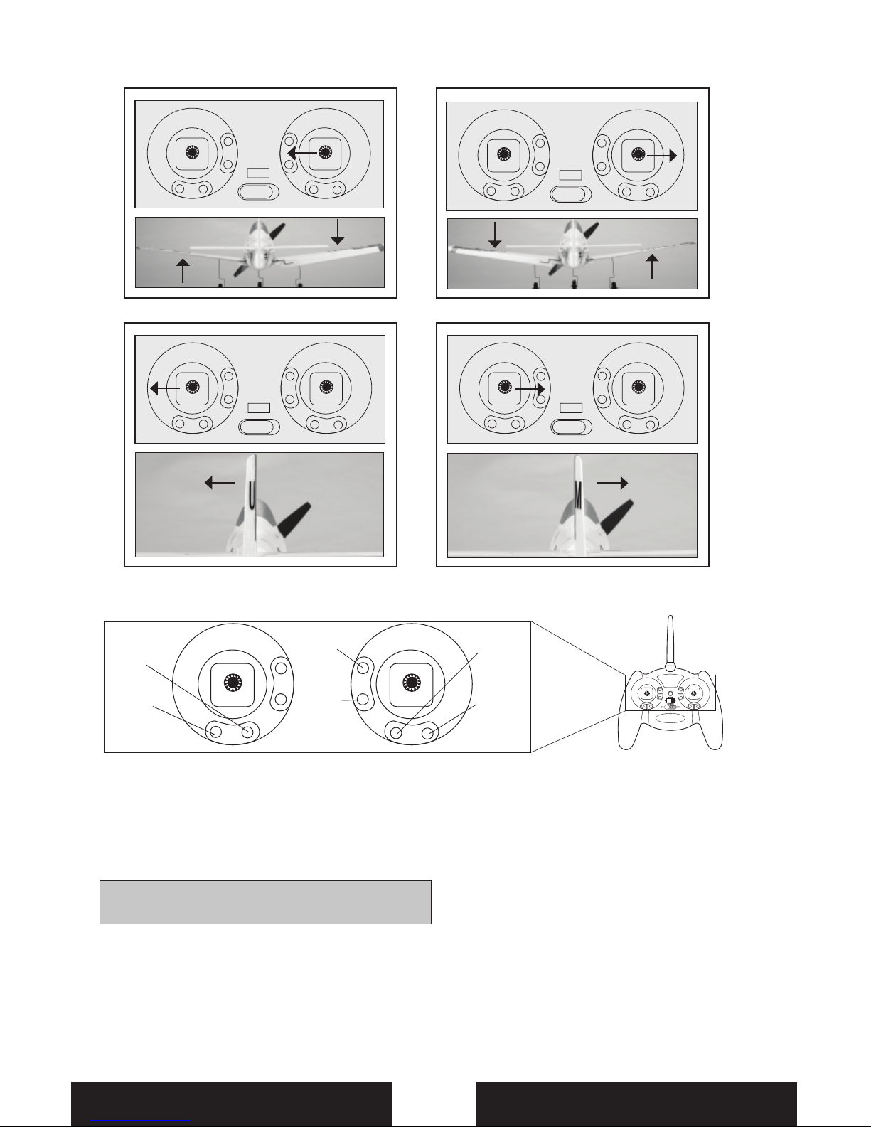
You should bind your aircraft and transmitter before doing these tests. Move the controls on the
transmitter to make sure aircraft control surfaces are moved correctly. (Mode 2 shown).
Control Direction Test
Elevator
Rudder
Trim
This transmitter’s dual rate feature lets the pilot change between high and low control rates for
the aileron, elevator, rudder and throttle channels.
When powered on, this transmitter is automatically in high-rate mode. •
Change rate modes by pushing the right-hand control stick down into the case until it clicks •
while the transmitter is powered on.
High-rate mode is shown by the transmitter’s LED glowing solid red. In high-rate mode the •
controls can reach their maximum values. This mode is typically preferred by experienced
pilots for maximum control authority.
Low-rate mode is shown by the transmitter’s LED blinking continuously. In low-rate mode •
the controls are reduced to a percentage of their maximum values. This mode is typically
preferred by (and best for) rst-time, low-time and other pilots interested in smoother and
more easily controlled hovering and ying.
EN
Page 9
9
Aileron
Rudder
Control Direction Test, continued
The transmitter (MLP4DSM) included with
the T-28 is the same transmitter included
in other Ultra Micro RTF versions. It also
functions identically to the transmitter
included with the E- ite mCX and mSR.
Note: Refer to any other transmitter’s manual
for reversing instructions.
Should the T-28’s electronic components
be used in another aircraft, you may nd it
necessary to reverse the operation of ight
control surfaces. See Servo Reversing in your
transmitter manual.
1. Be certain the battery is unplugged from
the aircraft and the transmitter is turned o .
2. Press and hold the digital trim button for
the surface you would like to reverse.
3. While holding the digital trim button, turn
the transmitter on.
4. Hold the digital trim buttons down for
approximately 5 seconds until you hear a
tone, con rming the selection.
5. Connect the ight battery and complete
the ight control test. Con rm all surfaces
operate in the correct direction.
Reverse Controls
Elevator
Normal
Aileron
Normal
Aileron
Reversed
Rudder
Normal
Rudder
Reversed
Elevator
Reversed
Elevator
Normal
EN
Page 10
10
Before rst ight or in the event of an
accident, check to make sure the ight control
surfaces are centered. It is much better to do
this mechanically due to the mechanical limit
of linear servos.
1. Make sure the transmitter’s trims are
centered, and if your transmitter has them,
sub-trims are set to zero (0).
2. Check to see if any of the ight control
surfaces are not centered.
3. If the surface is not centered, use a pair
of pliers and carefully lengthen or shorten
the pushrod by bending the U-shape in
the pushrod.
Control Centering
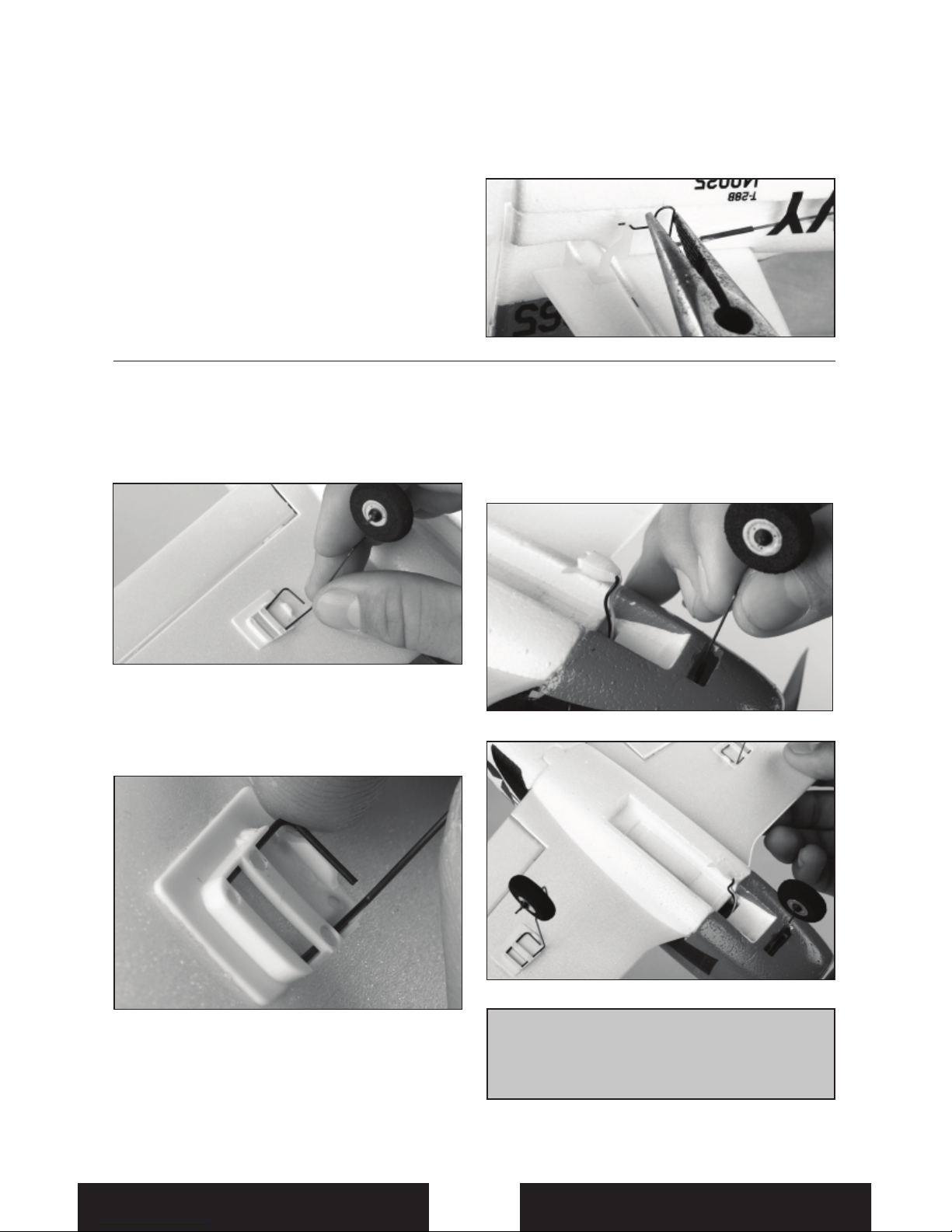
1. Remove the airplane and the landing gear
from the box.
2. Gently slide left and right mainlanding gear
into plastic mounting clips on the bottom
of the wings, orienting the struts toward the
front of the airplane as shown.
Note: Install left and right gear with the
vertical strut of the landing gear toward the
front of each wing. Install the bent wire of
each strut fully inside each mount.
3. Carefully slide the nose gear into the
plastic nose gear mount on the bottom of
the fuselage.
Installing Landing Gear
Note: You can adjust the nose gear height
by slightly pulling out the nose gear strut to
create a more positive angle of attack, and
more prop clearance.
EN
Page 11
11
Receiver Control Unit, Arming and Motor Control Test
Turn on the transmitter before connecting the
ight battery to the aircraft. Binding is done by
connecting the ight battery before turning
on the transmitter (see binding instructions
on page 6). Always disconnect and remove
the ight battery after use to prevent unsafe
power draining of the Li-Po battery.
Put the throttle stick at the •
lowest position
Power on the transmitter•
Connect the ight battery to the aircraft•
When the status LED on the receiver •
shines solid red, the receiver unit is
initialized and ready for ight.
When the throttle stick is in the idle •
position and throttle trim is in the lowest
position when the ight battery is
connected, the ESC/motor will be armed.
CAUTION: When armed, the motor will turn
the propeller in response to any
throttle movement.
If the status LED continues to ash red,
then bind the transmitter to the aircraft per
instructions on page 6.
Note: The throttle trim must be at the lowest
setting to arm the ESC.
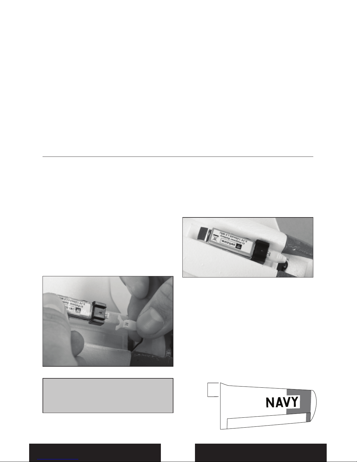
1. Install the fully charged ight battery in
the airplane.
2. Where necessary, apply a strip of hook
fastener to the back of the battery, opposite
the label.
3. Connect ight battery to Spektrum AR6400
plug. Refer to photo below for correct
alignment.
4. Attach ight battery to strip of loop fastener
on the bottom of the fuselage.
Adjusting Center of Gravity (CG)
The CG location is 30–32mm back from
leading edge of the wing at the root. This
CG location has been determined with the
ParkZone 1S 120mAh 3.7V Li-Po battery
installed in the middle of the battery cavity.
Note: The battery cavity is oversized to allow
for Center of Gravity adjustment. Start by
placing the battery in the center of the cavity,
and adjust as necessary.
Installing Flight Battery and Adjusting Center of Gravity
Note: Always disconnect the Li-Po from
the receiver of the airplane when not
ying. Failure to do so will render the
battery unusable.
30–32mm
EN
Page 12
12
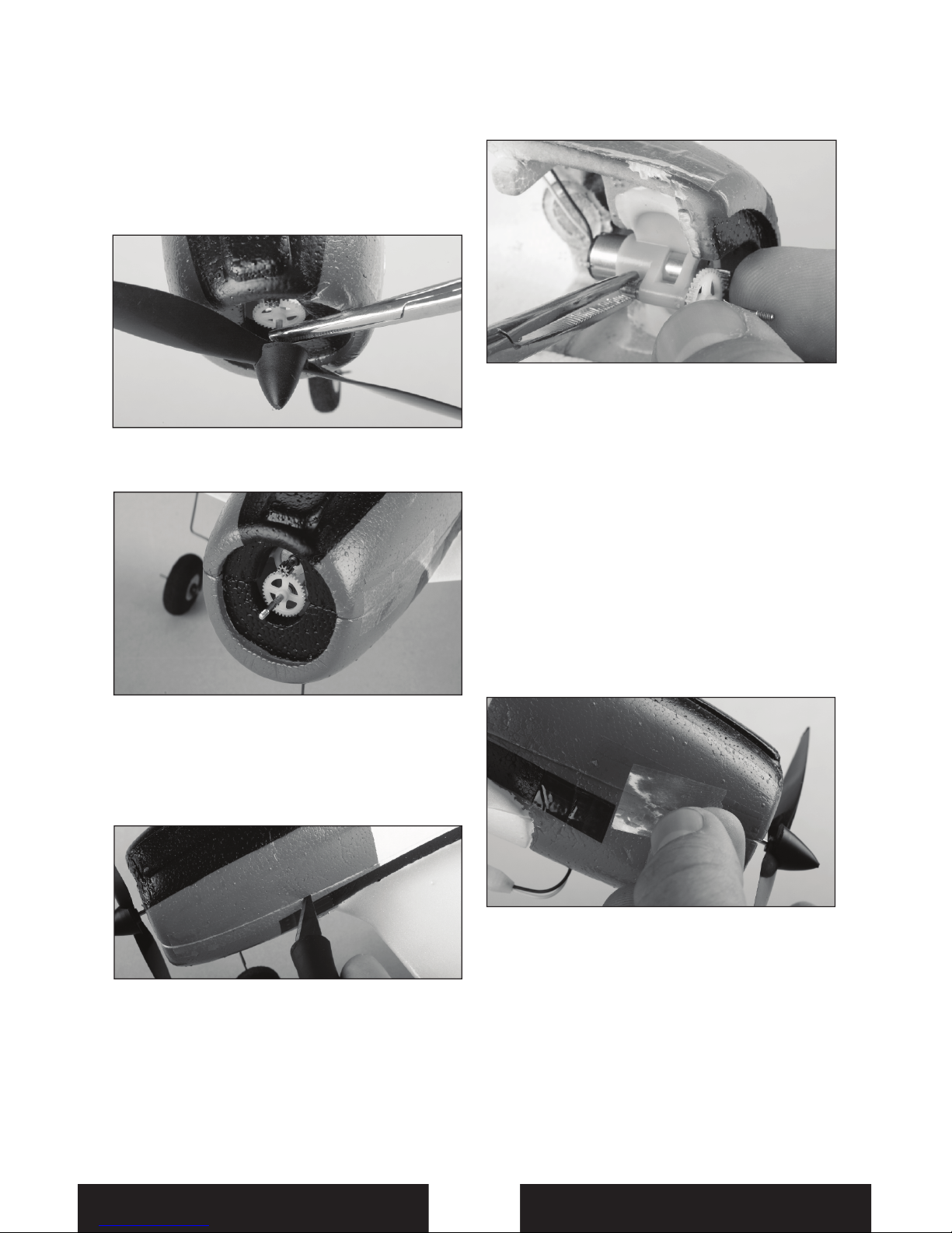
Propeller and Propeller Shaft Maintenance
CAUTION: DO NOT handle propeller
parts while the ight battery is
connected. Personal injury could result.
Remove Propeller
1. Hold the shaft using needle-nose pliers
or hemostats.
2. Remove the propeller by turning it
counterclockwise on the threaded shaft
Remove Propeller Shaft
1. Cut open the fuselage at the decal on one
side of the fuselage and on the turtle deck
(top of fuselage behind the canopy).
Note: Removing tape or decals will remove
paint from the fuselage.
2. While the fuselage is open, hold the white
nylon nut on the prop shaft using needle nose pliers or hemostats.
3. Turn the spur gear on the prop shaft
clockwise to remove the nut.
4. Gently pull the shaft from the gearbox.
Note: Make sure no parts fall into the fuselage
when removing the shaft.
Installing
1. Turn a 130mm x 70mm prop and spinner
clockwise on the prop shaft.
2. Install the prop shaft in the gearbox.
3. Hold the nylon nut on the back of the
prop shaft.
4. Turn the spur gear counterclockwise until
the nut is tightly installed on the shaft.
5. Assemble the fuselage with clear tape.
EN
Page 13
13
Flying
Always avoid ying near houses, trees, wires
and buildings. You should also be careful to
avoid ying in areas where there are many
people, such as busy parks, schoolyards,
or soccer elds. Consult local laws and
ordinances before choosing a location to y
your aircraft. We recommend only ying your
T-28 in light winds.
Place the T-28 in position for takeo (facing
into the wind if ying outdoors). Gradually
increase the throttle to ¾ to full, and steer with
the rudder. Pull back gently with the elevator
and climb to check trim. Once the trim is
adjusted, begin exploring the ight envelope
of the T-28.
Note: Due to the large propeller on the T-28, it
is possible to hit the prop on the ground while
landing. Make sure to are when landing and
try to land as smoothly as possible to minimize
hitting the prop. While this does not damage
the airplane it is possible to wear down the
tips of the propeller if ying from an abrasive
surface such as concrete
or asphalt.
Note: You can also raise the
nose gear to avoid further
prop strikes.
Failure to lower the throttle
stick and trim to the lowest
possible positions during a
crash could result in damage
to the ESC in the receiver unit, which may
require replacement.
Note: Crash damage is not covered under
warranty.
Repairs
Thanks to the T-28’s construction, repairs to
the foam can be made using foam-compatible
CA or tape. When parts are not repairable,
see the Replacement Parts List for ordering by
item number.
Flying Tips and Repairs
RTF
Re-binding Transmitter
The T-28 RTF comes pre-bound to the included DSM2 transmitter. If you need to re-bind your
airplane, follow the simple directions below.
1
5
2
3
4
Fully Charged
OFF
ON
A
B
6
7
8
Flashes
Beeps
Flashes
Wait
5 seconds
5-10
seconds
Always
decrease throttle at
propeller strike.
EN
Page 14

14
Troubleshooting Guide
PROBLEM
POSSIBLE CAUSE SOLUTION
Aircraft will not respond
to throttle but responds
to other controls
• Throttle not at idle at control
setup and/or throttle trim
too high.
• Throttle channel is reversed
• Reset controls with throttle stick
and throttle trim at lowest
setting
• Reverse throttle channel on
transmitter
Extra propeller noise or
extra vibration
• Damaged propeller and
spinner, gear shaft or motor
• Replace damaged parts
Reduced ight time or
aircraft underpowered
• Flight battery charge is low
• Propeller or gear shaft
damaged
• Flight battery damaged
• Gearbox not moving freely
• Flight conditions may be
too cold
• Completely recharge ight
battery
• Replace damaged parts
• Replace ight battery and follow
ight battery instructions
• Lubricate gear shaft and
bushings
• Make sure battery is warm
before use
LED on receiver ashes
and aircraft will not bind
to transmitter
• Less than a 5 second wait
after powering transmitter
and before connecting ight
battery to aircraft
• Transmitter too near aircraft
during binding process
• Batteries in transmitter low
• Disconnect then connect ight
battery to aircraft
• Move powered transmitter a few
feet from aircraft, disconnect
and connect ight battery
to aircraft
• Replace transmitter batteries
Control surface does
not move, or is slow to
respond to controls
• Control surface, control horn,
linkage or servo damage
• Wire damaged or connections
loose
• Flight battery charge is low
• Control trim out of adjustment
• Replace or repair damaged
parts and adjust controls
• Do a check of wires and
connections, connect or replace
as needed
• Fully recharge ight battery
• Adjust trims to restore full
control
Controls reversed
• Transmitter settings reversed • Do the Control Direction Test
and adjust controls
ontransmitter appropriately
Motor loses power
• Damage to motor, or power
components
• Do a check of batteries,
transmitter, receiver, ESC, motor
and wiring for damage (replace
as needed)
Motor power pulses
then motor loses power
• ESC uses default soft Low
Voltage Cuto (LVC)
• Recharge ight battery
EN
Page 15

15
Replacement Parts and Optional Parts
Number Description
PKZ1035
3.7V 120mAh Li-Po Battery
PKZ3240
DC 3.7V Li-Po Charger
EFL9051
130 x 70 Propeller with
Spinner (2)
PKZ3527
Gearbox without Motor
PKZ3528
Prop Shaft
PKZ3616
Motor
PKZU1502
Decal Sheet
PKZU1504
Main and Nose Landing Gear
PKZU1520
Wing with Ailerons
PKZU1522
Aileron Pushrod and
Linkages
PKZ3623
Aileron Bellcrank
PKZ3624
Motor and Gearbox
PKZU1525 Complete Tail Set
PKZU1526 Elevator/Rudder Pushrod Set
PKZU1567
Bare Fuselage: T-28
SPMAR6400
DSM2 6-Channel Ultra Micro
Receiver with ESC and Servos
SPMAS2000 1.5g Linear Servo
EFLH1066
Replacement Servo
Mechanics
EFLH1067
Replacement Servo
Retaining Collars
PKZ3052
Battery Connector with Wire
(Optional)
EFLB1201S
120mAh 3.7V 14C Li-Po
Battery (Optional)
EFLB1501S
150mAh 3.7V 12C Li-Po
Battery (Optional)
Number Description
EFLC1004
4-Port 3.7V Li-Po Charger
(Optional)
EFLC1005
AC to 6V DC Adapter
(Optional)
EFLC1005AU
AC to 6V DC Adapter (AU)
(Optional)
ELFC1005EU
AC to 6V DC Adapter (EU)
(Optional)
EFLC1005UK
AC to 6V DC Adapter (UK)
(Optional)
SPM6825
Linear Servo Reverser
(Optional)
SPMR5500
DX5e 5-Channel Transmitter
Mode 2 (Optional)
SPMR55001
DX5e 5-Channel Transmitter
Mode 1 (Optional)
SPMR6600
DX6i 6-Channel Transmitter
Mode 2 (Optional)
SPMR66001
DX6i 6-Channel Transmitter
Mode 1 (Optional)
SPMR6600E
DX6i 6-Channel Transmitter
Mode 2 (EU) (Optional)
SPMR66001E
DX6i 6-Channel Transmitter
Mode 1 (EU) (Optional)
SPMR7700
DX7 7-Channel Transmitter
Mode 2 (Optional)
SPMR77001
DX7 7-Channel Transmitter
Mode 1 (Optional)
SPMR7700E
DX7 7-Channel Transmitter
Mode 2 (EU) (Optional)
SPMR77001E
DX7 7-Channel Transmitter
Mode 1 (EU) (Optional)
Warranty and Repair Policy
Warranty Period
Exclusive Warranty- Horizon Hobby, Inc., (Horizon) warranties
that the Products purchased (the “Product”) will be free from
defects in materials and workmanship at the date of purchase
by the Purchaser.
Limited Warranty
Horizon reserves the right to change or modify this warranty
without notice and disclaims all other warranties, express
or implied.
(a) This warranty is limited to the original Purchaser
(“Purchaser”) and is not transferable. REPAIR OR
REPLACEMENT AS PROVIDED UNDER THIS WARRANTY
IS THE EXCLUSIVE REMEDY OF THE PURCHASER. This
warranty covers only those Products purchased from
an authorized Horizon dealer. Third party transactions
are not covered by this warranty. Proof of purchase is
required for all warranty claims.
(b) Limitations- HORIZON MAKES NO WARRANTY OR
REPRESENTATION, EXPRESS OR IMPLIED, ABOUT
NON-INFRINGEMENT, MERCHANTABILITY OR FITNESS FOR A
PARTICULAR PURPOSE OF THE PRODUCT. THE PURCHASER
ACKNOWLEDGES THAT THEY ALONE HAVE DETERMINED THAT
THE PRODUCT WILL SUITABLY MEET THE REQUIREMENTS OF
THE PURCHASER’S NTENDED USE.
(c) Purchaser Remedy- Horizon’s sole obligation hereunder
shall be that Horizon will, at its option, (i) repair or (ii)
replace, any Product determined by Horizon to be
EN
Page 16

16
defective. In the event of a defect, these are the Purchaser’s
exclusive remedies. Horizon reserves the right to inspect
any and all equipment involved in a warranty claim. Repair
or replacement decisions are at the sole discretion of
Horizon. This warranty does not cover cosmetic damage or
damage due to acts of God, accident, misuse, abuse,
negligence, commercial use, or modi cation of or to any
part of the Product.
This warranty does not cover damage due to improper installation, operation, maintenance, or attempted repair by anyone
other than Horizon. Return of any Product by Purchaser must
be approved in writing by Horizon before shipment.
Damage Limits
HORIZON SHALL NOT BE LIABLE FOR SPECIAL, INDIRECT OR
CONSEQUENTIAL DAMAGES, LOSS OF PROFITS OR PRODUCTION
OR COMMERCIAL LOSS IN ANY WAY CONNECTED WITH THE
PRODUCT, WHETHER SUCH CLAIM IS BASED IN CONTRACT,
WARRANTY, NEGLIGENCE, OR STRICT LIABILITY. Further, in no
event shall the liability of Horizon exceed the individual price
of the Product on which liability is asserted. As Horizon has no
control over use, setup, nal assembly, modi cation or misuse,
no liability shall be assumed nor accepted for any resulting
damage or injury. By the act of use, setup or assembly, the
user accepts all resulting liability.
If you as the Purchaser or user are not prepared to accept
the liability associated with the use of this Product, you are
advised to return this Product immediately in new and unused
condition to the place of purchase.
Law: These Terms are governed by Illinois law (without regard
to con ict of law principals).
Warranty Services
Questions, Assistance, and Repairs
Your local hobby store and/or place of purchase cannot provide
warranty support or repair. Once assembly, setup or use of the
Product has been started, you must contact Horizon directly.
This will enable Horizon to better answer your questions and
service you in the event that you may need any assistance. For
questions or assistance, please direct your email to productsupport@horizonhobby.com, or call 877.504.0233 toll free to
speak to a Product Support representative. You may also find
information on our website at www.horizonhobby.com.
Inspection or Repairs
If this Product needs to be inspected or repaired, please use
the Horizon Online Repair Request submission process found
on our website or call Horizon to obtain a Return Merchandise
Authorization (RMA) number. Pack the Product securely
using a shipping carton. Please note that original boxes may
be included, but are not designed to withstand the rigors of
shipping without additional protection. Ship via a carrier that
provides tracking and insurance for lost or damaged parcels, as
Horizon is not responsible for merchandise until it arrives and
is accepted at our facility. An Online Repair Request is available at www.horizonhobby.com http://www.horizonhobby.
com under the Repairs tab. If you do not have internet access,
please contact Horizon Product Support to obtain a RMA
number along with instructions for submitting your product
for repair. When calling Horizon, you will be asked to provide
your complete name, street address, email address and phone
number where you can be reached during business hours.
When sending product into Horizon, please include your RMA
number, a list of the included items, and a brief summary
of the problem. A copy of your original sales receipt must
be included for warranty consideration. Be sure your name,
address, and RMA number are clearly written on the outside of
the shipping carton.
Notice: Do not ship batteries to Horizon. If you have any issue
with a battery, please contact the appropriate Horizon Product
Support office.
Warranty Inspection and Repairs
To receive warranty service, you must include your original sales
receipt verifying the proof-of-purchase date. Provided warranty
conditions have been met, your Product will be repaired or replaced free of charge. Repair or replacement decisions are at the sole
discretion of Horizon Hobby.
Non-Warranty Repairs
Should your repair not be covered by warranty the repair will
be completed and payment will be required without notification or estimate of the expense unless the expense exceeds
50% of the retail purchase cost. By submitting the item for
repair you are agreeing to payment of the repair without
notification. Repair estimates are available upon request.
You must include this request with your repair. Non-warranty
repair estimates will be billed a minimum of ½ hour of labor.
In addition you will be billed for return freight. Horizon accepts
money orders and cashiers checks, as well as Visa, MasterCard,
American Express, and Discover cards. By submitting any
item to Horizon for inspection or repair, you are agreeing to
Horizon’s Terms and Conditions found on our website under
the Repairs tab.
Contact Information
Country of
Purchase
Horizon Hobby Address Phone Number / Email Address
Horizon Service Center
(Electronics and
engines)
4105 Fieldstone Rd
Champaign, Illinois
61822 USA
877-504-0233
productsupport@horizonhobby.com
Horizon Product
Support (All other
products)
4105 Fieldstone Rd
Champaign, Illinois
61822 USA
877-504-0233
productsupport@horizonhobby.com
United Kingdom Horizon Hobby Limited
Units 1-4 Ployters Rd
Staple Tye
Harlow, Essex
CM18 7NS
United Kingdom
+44 (0) 1279 641 097
sales@horizonhobby.co.uk
Germany
Horizon Technischer
Service
Hamburger Str. 10
25335 Elmshorn
Germany
+49 4121 46199 66
service@horizonhobby.de
France Horizon Hobby SAS
14 Rue Gustave Eiffel
Zone d’Activité du Réveil Matin
91230 Montgeron
+33 (0) 1 60 47 44 70
United States
of America
EN
Page 17

17
Declaration of Conformity
Compliance Information for the European Union
(in accordance with ISO/IEC 17050-1)
No. HH2010072901
Product(s): PKZ T-28 Trojan Ultra Micro RTF
Item Number(s): PKZU1500, PKZU1500M1
Equipment class: 1
The object of declaration described above is in conformity with the requirements of the
specifications listed below, following the provisions of the European R&TTE directive 1999/5/EC:
EN 300-328 Technical requirements for Radio equipment.
EN 301 489-1, 301 489-17 General EMC requirements
EN 60950 Safety
Signed for and on behalf of:
Horizon Hobby, Inc.
Champaign, IL USA
July 29, 2010
Steven A. Hall
Vice President
International Operations and Risk Management
Horizon Hobby, Inc.
FCC Information
This device complies with part 15 of the FCC rules. Operation is subject to the following two
conditions: (1)This device may not cause harmful interference, and (2) this device must accept
any interference received, including interference that may cause undesired operation.
Caution: Changes or modi cations not expressly approved by the party responsible for
compliance could void the user’s authority to operate the equipment.
This product contains a radio transmitter with wireless technology which has been tested and
found to be compliant with the applicable regulations governing a radio transmitter in the
2.400GHz to 2.4835GHz frequency range.
EN
Declaration of Conformity
(in accordance with ISO/IEC 17050-1)
No. HH2010072902
Product(s): PKZ T-28 Trojan Ultra Micro BNF
Item Number(s): PKZU1580
Equipment class: 1
The object of declaration described above is in conformity with the requirements of the
specifications listed below, following the provisions of the European R&TTE directive 1999/5/EC:
EN 301 489-1, 301 489-17 General EMC requirements
Signed for and on behalf of:
Horizon Hobby, Inc.
Champaign, IL USA
July 29, 2010
Steven A. Hall
Vice President
International Operations and Risk Management
Horizon Hobby, Inc.
Page 18

18
Instructions for disposal of WEEE by users in the
European Union
This product must not be disposed of with other waste. Instead, it is the user’s
responsibility to dispose of their waste equipment by handing it over to a
designated collections point for the recycling of waste electrical and electronic
equipment. The separate collection and recycling of your waste equipment at
the time of disposal will help to conserve natural resources and ensure that it is
recycled in a manner that protects human health and the environment. For more
information about where you can drop o your waste equipment for recycling,
please contact your local city o ce, your household waste disposal service or
where you purchased the product.
EN
Page 19
19
Sicherheitshinweise und
Warnungen
Als Nutzer dieses Produktes, sind Sie allein
verantwortlich, es in einer Art und Weise
zu benutzen, die eine eigene Gefährdung
und die anderer oder Beschädigung an
anderem Eigentum ausschließt.
Alters Empfehlung: ab 14 Jahre. Das ist kein
Spielzeug. Dieses Produkt ist nicht für den
Gebrauch von Kindern ohne direkte Aufsicht
durch ihre Eltern geeignet.
Das Modell ist ferngesteuert und anfällig für
bestimmte äußere Ein üsse. Diese Ein üsse
können zum vorübergehenden Verlust der
Steuerfähigkeit führen, so dass es immer
sinnvoll ist genügend Sicherheitsabstand in
alle Richtungen um das Modell zu haben.
Alters Empfehlung: 14 Jahre oder älter.
Das ist keine Spielzeug. Diese Produkt ist
nicht geeignet für Kinder ohne die direkte
Aufsicht Ihrer Eltern
Fliegen Sie nie mit fast leeren oder -
schwachen Senderbatterien
Fliegen Sie immer weit weg genug von -
Autos, Verkehr oder Personen
Fliegen Sie Ihr Modell nicht auf der -
Straße oder belebten Plätzen
Beachten Sie vorsichtig alle Hinweise und Warnungen für das Modell und
allen dazu gehörigen Equipment.
Halten Sie alle Chemikalien, Kleinteile und elektrische Bauteile aus der
Reichweite von Kindern.
Feuchtigkeit beschädigt die Elektronik. Vermeiden Sie jeglichen Wasserkontakt
mit allen Bauteilen, die nicht dafür
gemacht oder entsprechend
geschützt sind.
· Lecken Sie niemals an Teilen von Ihrem
Modell oder nehmen diese in den
Mund, da diese Sie ernsthaft verletzten
oder töten können.
Warnung: Lesen Sie sorgfältig die gesamte Bedienungsanleitung durch und machen
sich vor dem Betrieb mit dem Produkt vertraut. Falscher und oder nicht sachgemäßer
Umgang kann zu Beschädigungen am Produkt, eigenen und fremden Eigentum und
ernsthaften Verletzungen führen.
Bitte beachten Sie, dass dieses Produkt ein hoch entwickeltes Hobby Produkt und
kein Spielzeug ist. Es erfordert bei dem Betrieb Aufmerksamkeit und grundlegende
mechanische Fähigkeiten. Falscher, nicht sachgemäßer Umgang kann zu Beschädigungen
an eigenem oder fremden Eigentum oder zu Verletzungen an sich selbst oder
Dritter führen. Versuchen Sie nicht dieses Produkt auseinander zu bauen, oder es mit
Komponenten zu betreiben, die nicht ausdrücklich mit Genehmigung von Horizon Hobby
dafür geeignet sind. Dieses Produkt ist nicht für den Gebrauch von Kindern ohne direkte
Aufsicht durch ihre Eltern bestimmt.
Die Bedienungsanleitung enthält Anweisungen und wichtige Informationen für die
Sicherheit und Betrieb. Es ist daher notwendig, allen darin enthaltenen Anweisungen
und Warnungen Folge zu leisten und diese Anleitung vor dem Zusammenbau und
Inbetriebnahme sorgfältig durch zu lesen.
Hinweis:
Alle Anweisungen, Garantien und dazugehörigen Dokumente können ohne Ankündigung von
Horizon Hobby geändert werden. Eine aktuelle Version ersehen Sie bitte unter:
www.horizonhobby.com unter support für dieses Produkt.
Erklärung der Begri e
Die folgenden Begri e erklären die Gefährdungsstufen im Umgang mit dem Produkt:
Hinweis: Verfahren die nicht ordnungsgemäß durchgeführt werden, beinhalten die
Möglichkeiten einer Beschädigung und maximal ein kleines Risiko einer Verletzung.
Achtung: Verfahren die nicht ordnungsgemäß durchgeführt werden, beinhalten die
Wahrscheinlichkeit einer Beschädigung und das Risiko einer ernsthaften Verletzung.
Warnung: Verfahren die nicht ordnungsgemäß durchgeführt werden führen zu
Beschädigungen und oder ernsthaften Verletzung bis hin zum Tod. damage, collateral damage,
and serious injury OR create a high probability of super cial injury.
DE
Page 20

20
Die T-28 in der Ultra Micro Serie ist ein echtes Muss für alle fortgeschrittenen bis erfahrene
Piloten. Wie das Original bietet das Modell viel Leistung für sportliches Fliegen, macht aber
aber auch im Langsam ugbereich viel Freude für Touch and Gos. Besonders gelungen ist
hier die Lackierung im US Navy trim.
Wie alle Micros läßt sich dieses wunderschöne Warbird selbst im Garten iegen.
Produkt Registrierung: Registrieren Sie bitte Ihr Produkt unter www.parkzone.com / register.
Sicherheitshinweise und Warnungen ....... 19
Einleitung ............................................................ 20
Vorbereitung für den Erst ug ...................... 20
Tipps zur Wartung ............................................ 20
Akku Warnungen .............................................. 21
Niederspannungsabschaltung (LVC) ........ 21
Laden des Akkus ................................................22
Binden von Sender und Empfänger ...........23
Einsetzen der Senderakkus ............................23
Sender Funktionen .......................................... 24
Digitale Trimmungen ...................................... 24
Dual Rate Funktionen ......................................24
Sender Kontrollen .............................................24
Reversieren der Kontrollen ............................25
Zentrieren der Kontrollen ..............................26
Montage des Fahrwerks .................................26
Beschreibung des Empfängers ....................27
Motor-Funktions Test .......................................27
Einsetzen des Akkus ...........................................27
Einstellen des Schwerpunktes ......................27
Wechsel von Propeller und Propellerwelle. 28
Tipps für das Fliegen ........................................29
Reparaturen .........................................................29
Binden des Senders ..........................................29
Hilfestellung zur Probelmlösung .................30
Ersatz- und optionale Teile ............................31
Garantie und Service........................................32
Kontakt Information .........................................32
Vorbereitung für den Erstflug
Entnehmen und überprüfen Sie alle -
Packungsteile.
Laden Sie den Flugakku. -
Montieren Sie das Fahrgestell in die Halterung auf der Unterseite der
Trag ächen und Rumpf.
Setzten Sie die 4 AA Batterien in das Ladegerät ein.
Setzen Sie die Batterien in den Sender ein (nur RTF Version )
Laden Sie den Flugakku. -
Schließen Sie dann den Flugakku an. -
Binden Sie den Empfänger mit Ihren Spektrum oder DSM2 ausgerüsteten
Sender.
Testen Sie die Kontrollen. -
Machen Sie sich mit den Kontrollen vertraut.
Justieren Sie die Kontrollen und Ruder -
Stellen Sie den Schwerpunkt ein. -
Machen Sie einen Reichweitentest -
Finden Sie eine geeignete Fläche -
zum Fliegen.
Planen Sie Ihren Flug nach den -
örtlichen Gegebenheiten.
Wartung nach dem Flug
Trennen Sie den Flugakku vom -
Empfänger
Schalten Sie den Sender aus Laden Sie den Flugakku auf Reparieren oder ersetzen Sie -
beschädigte Teile.
Beobachten Sie die Akkuladung und -
lagern Sie den Akku nicht im Flugzeug.
Machen Sie sich Notizen über die -
Flugbedingungen, ihren Flugplan und
Planung für zukünftige Flüge.
Inhaltsverzeichnis
T-28 Spezi kationen
Spannweite
Länge:
Gewicht:
16.8 in (426mm)
13.5 in (343mm)
1.30 oz (38 g)
T-28 Eigenschaften
Bind-N-Fly
Version
Ready to Fly
Version
Onboard Electronics
Spektrum AR6400
Empfänger/Servos/
Regler
eingebaut eingebaut
Akku
120mAh 3.7V 14C
Li-Po
eingebaut eingebaut
Ladegerät
1S 3,7 V LiPo Akku
Ladegerät
eingebaut eingebaut
Sender
DSM2 Flugzeug
Sender
Separat
erhältlich
eingebaut
DE
Page 21
21
Akku Warnungen und Richtlinien
Das im Lieferumfang enthaltene Akku
Ladegerät ist für das sichere Laden des LiPo
Flugakkus entwickelt worden.
Sie müssen vor dem Laden, Gebrauch
oder Handhabung der Akkus folgende
Sicherheitshinweise und Anweisungen lesen.
Achtung: Bitte befolgen Sie exakt alle
Instruktionen und Warnungen. Falscher
oder nicht sachgemäßer Gebrauch von LiPo
Akkus kann zu Feuer, der Beschädigung von
eigenem oder fremden Eigentum sowie
Verletzungen führen.
Bei dem Laden oder Gebrauch von -
Li-Po Akku übernehmen Sie alle Risiken
die damit einher gehen. Sollten Sie mit
diesen Konditionen nicht einverstanden
sein, bringen Sie Ihr Modell unbenutzt
und originalverpackt an den Ort des
Kaufes zurück.
Benutzen Sie zum Au aden des Flugakkus -
kein Ni-Cd oder Ni-Mh Ladegerät. Sollte
das Flugakku mit einem ungeeigneten
Ladegerät geladen werden, kann dieses
zu Sachbeschädigung Feuer und
Körperverletzungen führen.
Sollte beim Laden oder im Flug der Akku beginnen sich aufzublähen oder
anzuschwellen, stoppen Sie den
Ladevorgang oder den Flug unverzüglich.
Ziehen Sie den Akkustecker und bringen
Sie den Akku in eine sichere o ene
Gegend, weit weg von ent ammbaren
Materialien. Beobachten Sie den Akku für
weitere 15 Minuten aus sicherer
Entfernung. Ein fortgesetztes Laden oder
Fliegen eines aufblähenden oder
anschwellenden Akku kann ein Feuer zur
Folge haben.
Lagern Sie den Akku bei Raumtemperatur an einem trockenen Ort.
Beim Transportieren oder vorüberge- henden Lagern des Akkus sollte der
Temperaturbereich zwischen 4,4°C und
48,9°C liegen. Lagern Sie den Akku nicht
im Fahrzeug oder in direkten Sonnenlicht.
Der Akku kann beschädigt werden oder
Feuer fangen.
Li-Po Akkus sollten nicht bei Last unter 3V entladen werden.
Akku Warnungen
Niederspannungsabschaltung
Die T-28ist mit einer Niederspannungsabschaltung ausgestattet, die bei einer
Akkuspannung von 3 Volt pro Zelle unter Last
aktiv wird.
Unabhängig von der Gasknüppelstellung
wird dann die Leistung reduziert, um einen
Absinken der Zellenspannung unter 3 Volt
zu verhindern.
Nach aktivierter Niederspannungsabschaltung
ist es zwar möglich das Flugzeug weiter
zu iegen, wir raten jedoch dringend
davon ab, da eine weitere Entladung den
Akku beschädigen kann. Dieses kann eine
verminderte Leistung, geringere Flugzeit
oder den Ausfall des Akkus zur Folge
haben. Ein weiteres Entladen / Fliegen nach
aktivierung der Niederspannungsabschaltung,
kann ebenfalls zum Verlust der Kontrollen
führen, wenn die Akkuspannung unter die
Mindesbetriebsspannung des
Empfängers fällt.
Achten Sie während des Fluges auf die Akkuspannung. Benötigt das Flugzeug größere
Gaseingaben als normalerweise oder zu
Anfang des Fluges landen Sie die Stinson
Reliant.
Hinweis: Die Leistungsfähigkeit des Akkus
ist bei niedrigen Temperaturen reduziert.
Lassen Sie bitte den Akku vor dem Flug nicht
auskühlen.
Achtung: Trennen Sie nach dem Fliegen
immer den Akku vom Empfänger um eine
Tiefentladung zu verhindern. LiPo Akkus
benötigen regelmäßige Wartung um sie im
ladefähigen Zustand zu erhalten.
Laden Sie
Akkus niemals
unbeaufsichtigt.
WARNUNG
Laden Sie Akkus
immer weit weg von
brennbaren
Materialien.
WARNUNG
Laden Sie niemals
Akkus ausserhalb
ihres sicheren
Temperaturbereiches.
WARNUNG
Laden Sie niemals
Akkus ausserhalb
der Spezifikationen.
WARNUNG
Lagern Sie Akkus
immer sicher.
WARNUNG
Laden Sie niemals
beschädigte Akkus.
WARNUNG
DE
Page 22

22
Laden des Akkus
Der Ladevorgang
1. Laden Sie nur Akkus die abgekühlt sind und die sie anfassen können. Überprüfen Sie vor dem Laden
den Akku ob er beschädigt, verbogen oder angeschwollen ist.
2. Nehmen Sie den Gehäusedeckel an der Unterseite des Ladegerätes ab und setzen die vier AA
Batterien ein. Setzen Sie den Deckel danach wieder auf.
3. Schieben Sie den Akku in den Ladeschacht des Ladegerätes. Der Anschluß des Akkus ist so geformt,
dass der Akku nur in einer Richtung mit dem Stecker voran in den Ladeschacht paßt. Normalerweise
zeigt hier das Etikett nach vorne. Überprüfen Sie den richtigen Sitz und Polarität wenn Sie den Akku
eingeschoben haben bevor Sie fortfahren.
4. Schieben Sie den Akku vorsichtig in den Ladeschlitz.
5. Ist der Akku richtig eingeschoben leuchtet die LED auf dem Ladegerät Rot und zeigt damit den
Ladevorgang an.
6. Der Ladevorgang eines leeren 120mAh ( nicht tiefentladenen) Akkus dauert ca. 30 - 40 Minuten. Ist
die vollständige Ladung nahezu erreicht fängt die LED an zu blinken.
7. Ist der Akku vollständig geladen blinkt die LED alle 20 Sekunden und geht dann aus.
Hinweis: Sollte die LED nach Entnahme des Akkus weiter leuchten sind die Batterien des Ladegeräts
entladen.
8. Entfernen Sie nach dem Ladevorgang immer die Akku aus dem Ladegerät.
Achtung: Ein Überladen kann Feuer zur Folge haben.
Warnung: Falscher oder nicht sachgemäßer Umgang kann ernsthafte Beschädigungen
oder bei längerer Zeitüberschreitung Feuer zur Folge haben. Seien Sie immer aufmerksam
bei Benutzung des Ladegerätes.
Warnung: Sollten Sie bei dem Laden eine Laderate größer als 1 C wählen, kann dieses Feuer
zur Folge haben.
Ihre T-28 wird mit einem 1S 3,7 Volt LiPo Akku
Ladegerät und 1S LiPo Akku geliefert.
Es ist sehr wichtig, dass sie den Akku nur mit
dem im Lieferumfang enthaltenen Ladegerät
oder mit dem E- ite® Celectra™ 4-port
ladegerät (EFLC1004). laden.
Laden Sie den Akku während Sie das Flugzeug
montieren, Sie benötigen für die weiteren
Schritte einen geladenen Akku.
DE
Page 23

23
RTF
®
Der Bindevorgang verbindet den Sender mit dem Empfänger durch die Übermittlung eines
GUID (Globally Unique Identi er) Signalcodes. Der Bindevorgang ist für den Betrieb notwendig.
Um Ihre T-28 mit dem gewählten Empfänger zu binden, folgen Sie bitte den untenstehenden
Anweisungen.
Ihr T-28 RTF Sender wird bereit an den Sender gebunden geliefert. Sie brauchen nur noch die
Batterien einsetzen.
Einsetzen der Senderakkus
3
4
1
2
6
5
7
Die T -28 benötigt einen DSM2 Sender. Die folgenden Liste beinhaltet Spektrum oder JR DSM2 ausgerüstete Sender
die kompatibel sind. Sollte Ihr Sender nicht gelistet sein kontaktieren Sie bitte den Service von Horizon Hobby
• E- ite MLP4DSM • E- ite LP5DSM • ParkZone Vapor® Transmitter • JR X9503
• ParkZone Ember® 2 Transmitter • JR 12X 2.4 • JR X9303 2.4 • HP6DSM
• Spektrum DX5e • Spektrum DX6i • Spektrum DX7/DX7se
9
Informationen zum Binden
1. Bitte lesen Sie die Bindeanweisungen Ihres Senders.
2. Stellen Sie sicher, dass der Flugakku nicht angeschlossen ist.
3. Schalten Sie den Sender aus.
4. Schließen Sie den Flugakku an den Empfänger an
5.
Aktivieren Sie den Bindevorgang des Senders. Sollten Sie einen
MLP4DSM Sender verwenden, drücken Sie den linken Stick vertikal in
das in das Gehäuse bis Sie ein Klicken hören.
6. Stellen Sie sicher, dass die Senderkontrollen auf neutral und das Gas
auf Leerlauf steht.
7. Nach ca. 5 bis 10 Sekunden leuchtet die Status LED auf dem Empfänger
und der Bindevorgang ist ausgeführt.
Hinweis: Sollte die LED nicht dauerhaft leuchten, sehen Sie bitte in der
Hilfestellung zur Problemlösung nach
Stellen Sie vor jedem Flug sicher, dass zuerst der Sender eingeschaltet ist und warten fünf
Sekunden bis Sie den Flugakku anschließen. In dieser Zeit scant der Sender und sichert zwei
freie Frequenzen.
Sollte der Flugakku zu schnell angeschlossen werden, kann es sein, dass diese Verbindung
nicht zustande kommt. Für diesen Fall lassen Sie einfach den Sender eingeschaltet und
verbinden den Flugakku erneut.
Vermeiden Sie mehrere Sender und Empfänger gleichzeitig zu binden oder den Bindevorgang
in der Nähe von großen metallischen Objekten durchzuführen. Halten Sie zu dem Flugzeug bei
dem Binden min. 50 cm Abstand.
Binden von Sender und Empfänger
Additional Binding Information
Die Liste ist komplett nach Drucklegungsdatum. Zusätzliche Sender können in Zukunft verfügbar sein.
DE
Page 24

24
Höhenrudertrimmung
Seitenrudertrimmung
Gastrimmung
Querrudertrimmung
Gas / Querruder
Funktion
Höhenruder / Seitenruder
Funktion
Mode 1
Mode 2
Sender Kontrollen
Digitale Trimmungen
Der ParkZone 4- Kanal 2.4Ghz DSM2 Sender ist zur Feineinstellung der Ruder mit digitalen
Trimmungen ausgestattet. Nutzen Sie diese Trimmungen um vor dem ersten Flug die Ruder zu
zentrieren.
Hinweis: Wenn Sie die Trimmung drücken, hören Sie einen Ton der je weiter Sie die Trimmung
drücken immer höher wird. Der mittlere Ton de niert die Mittelstellung, am Ende des
Trimmweges hören Sie eine Tonfolge.
Dual Rate Funktion
RTF
Vor diesem Test sollten Sie das Flugzeug mit dem Sender gebunden haben um zu überprüfen
ob die Steuerung einwandfrei funktioniert. (Mode2 ist abgebildet)
Test der Kontrollen
Höhenruder
Sie können mit der Dual Rate Funktion bei dem Sender zwischen für die Höhen- Seiten- und
Querruder zwischen großen und kleinen Steuerausschlägen wählen.
Wenn der Sender eingeschaltet wird be ndet er sich automatisch im Mode mit dem -
großen Ausschlägen
Wechseln Sie auf kleine Ausschläge in dem Sie den rechten Steuerknüppel in das Gehäuse -
drücken, bis Sie ein Klicken hören wenn der Sender eingeschaltet ist.
Der Mode mit den großen Steuerausschläge wird Ihnen durch das Leuchten der LED auf dem Sender angezeigt. In diesem Mode erreichen Sie die größten Steuerausschläge. Dieser
Mode wird von erfahrenen Piloten bevorzugt.
Der Mode mit den kleinen Ausschlägen wird durch das Blinken der LED auf dem Sender angezeigt.
In diesem Mode sind die Ausschläge reduziert, von daher eignet er sich sehr gut für die ersten Flüge oder für den Gelegenheitspiloten.
Gas / Querruder
Funktion
Höhenruder / Seitenruder
Funktion
Seitenrudertrimmung
Gastrimmung
Höhenrudertrimmung
Querrudertrimmung
DE
Page 25

25
Querruder
Seitenruder
Test der Kontrollen
Reversieren der Steuerung
Der Sender MLPD4DSM der mit der T-28
geliefert wird, ist der gleiche Sender, der auch
im Lieferumfang von anderen Ultra Micro
Sendern ist.
Hinweis: Für des Reversieren beianderen
Sendern sehen Sie bitte in der Bedienungsanleitung des Senders nach.
Sollte die Elektronik der T-28 in andere
Flugzeuge eingebaut werden, ist es vielleicht
notwendig die Steuerung zu reversieren.
Zum Reversieren des Seiten- und Höhenruders
folgen Sie bitte diesen Anweisungen:
1. Stellen Sie sicher, dass der Flugakku nicht
angeschlossen und der Sender
ausgeschaltet ist.
2. Drücken Sie den digitalen Trimmbutton der
Funktion die Sie reversieren möchten.
3. Halten Sie den entsprechenden
Trimmbutton fest und schalten Sie den
Sender ein.
4. Halten Sie den entsprechenden
Trimmbutton für ca. 5 Sekunden fest bis
ein Ton Ihnen die Einstellung quittiert.
5. Schließen Sie den Flugakku an und
überprüfen Sie Ihre Einstellungen.
Reversieren der Kontrollen
Elevator
Normal
Querruder
normal
Querruder
reversiert
Seitenruder
Normal
Seitenruder
reversiert
Höhenruder
reverisert
Höhenruder
normal
DE
Page 26

26
Vor Ihrem Erst ug oder nach einer Reparatur
sollten Sie die Ruder zentrieren.
Durch die mechanische Begrenzung der
Servotrimmung ist es besser die erste
Trimmung manuel vorzunehmen.
1. Stellen Sie sicher, dass alle Trimmungen
oder auch der Subtrimm des Senders
zentriert ist.
2. Überprüfen ob alle Ruder zentriert sind.
3. Sollte ein Ruder nicht zentriert sein, drücken
Sie vorsichtig mit einer Spitzzange den
Drahtbogen zusammen oder auseinander.
Zentrieren der Kontrollen
1. Nehmen Sie das Flugzeug und das
Fahrwerk aus dem Karton.
2. Schieben Sie vorsichtig wie abgebildet
das linke und rechte Hauptfahrwerk in
die Halterung unter den Trag ächen. Die
Fahrwerksbeine zeigen dabei nach vorne.
Das quadratische geformte Drahtende muß
vollständig in die Halterung eingeschoben
werden.
3. Carefully slide the nose gear into the
plastic nose gear mount on the bottom of
the fuselage.
Montage des Fahrwerkes
Hinweis: Sie können das Bugrad mit
Halterung zur Erhöhung der Bodenfreiheit
und des Anstellwinkels etwas aus der
Halterung ziehen.
DE
Page 27

27
Beschreibung des Empfängers, Motor-Funktions Test
Schalten Sie als erstes den Sender ein bevor
Sie den Flugakku mit dem Empfänger
verbinden. ( Der Empfänger muß mit dem
Sender gebunden sein, siehe Seite 6)
Trennen Sie nach dem Fliegen immer den
Akku vom Empfänger, um eine mögliche
Tiefentladung des Akkus zu vermeiden
Bringen Sie den Gasknüppel auf die unterste Posion.
Schalten Sie den Sender ein. -
Verbinden Sie den Akku mit dem Empfänger.
Leuchtet die Status LED auf dem Empfänger Rot ist der Empfänger
initialisert und fugbereit.
Sie müssen den Gasknüppel auf Leerlauf und die Trimmung auf die unterste
Position bringen damit der Regler
scharf schaltet.
Achtung: Ist der Regler schargeschaltet dreht
der Motor sofort bei Eingabe am Gasknüppel.
Sollte die LED weiter ROT blinken muss der
Empfänger an den Sender gebunden werden.
Hinweis: Der Gasknüppel muß auf der
untersten möglichen Position stehen um den
Regler zu armieren.
1. Kleben Sie falls notwendig einen Streifen
Klettband auf die Rückseite des Akkus.
2. Verbinden Sie den Akku mit dem Stecker
des AR6400 Empfängers.
3. Setzen Sie wie abgebildet das Akku in die
Aussparung am Rumpf ein.
4. Attach ight battery to strip of loop fastener
on the bottom of the fuselage.
Einstellen des Schwerpunktes
Die Position des Schwerpunktes be ndet
sich 30 - 32mm hinter der Vorderkante der
Trag äche. Der Schwerpunkt wurde mit dem
Parkzone 1S 120mAh 3,7V LiPo Akku in der
Mitte der Akkuaussparung ermittelt.
Hinweis: Die Akkuaussparung
ist länger als das Akku, um
Schwerpunktanpassungen zu
ermöglichen. Starten Sie bei neuen
Anpassungen immer aus der Mitte der
Aussparung.
Einsetzen des Akkus und Einstellen des Schwerpunktes
Note: Always disconnect the Li-Po from
the receiver of the airplane when not
ying. Failure to do so will render the
battery unusable.
30–32mm
DE
Page 28

28
Wechsel von Propeller und Propellerwelle
Achtung: Bitte arbeiten Sie nicht am Propeller
wenn der Flugakku angeschlossen ist. Sie
könnten sich dabei verletzen.
Entfernen des Propellers
1. Halten Sie die Propellerwelle mit einer
Pinzette oder schmalen Zange fest.
2. Drehen Sie den Propeller gegen den
Uhrzeigersinn von der Welle
Austausch der Propellerwelle
1. Schneiden Sie an der Rumpfmitte wie
abgebildet die Aufkleber ein um den
Rumpf zu ö nen. (top of fuselage behind
the canopy).
Hinweis: Bei dem Abziehen von Aufklebern
oder Klebestreifen kann Farbe mit entfernt
werden.
2. Halten Sie bei geö neteten Rumpf die
Kunsto mutter an der Propellerwelle mit
einer Spitzzange oder Pinzette fest.
3. Drehen Sie das Zahnrad der Propellerwelle
im Uhrzeigersinn um die Kunsto mutter
zu lösen.
4. Ziehen Sie vorsichtig die Welle aus der
Halterung.
Hinweis: Bitte achten Sie darauf, dass keine
Teile in den Rumpf fallen.
Einbau
1. Drehen Sie den 130mm x 70mm Propeller
und Spinner auf die Propellerwelle.
2. Schieben Sie den Propeller samt Welle
wieder in die Halterung / Getriebebox.
3. Schrauben Sie die Nylonschraube am
Ende der Propellerwelle fest in dem Sie den
Propeller mit Welle gegen den
Uhrzeigersinn drehen.
4. Überprüfen Sie ob die Befestigungsmutter
fest sitzt.
5. Schließen Sie den Rumpf wieder mit einem
Stück klaren Klebeband.
DE
Page 29

29
Fliegen
Vermeiden Sie es in der Nähe von Häusern,
Bäumen Telefon oder Strommasten und
Gebäuden zu iegen.
Fliegen Sie nicht in der Nähe von Menschen
wie in Parks, Schulhöfen und Fußballfeldern.
Bitte beachten Sie immer lokale Vorschriften.
Wir empfehlen die T-28 nur bis leichten Wind
zu iegen
Stellen Sie die- T-28 auf Ihre Startposition.
Sollten Sie draußen iegen, muß der Start
gegen den Wind erfolgen.
Erhöhen Sie das Gas schrittweise auf 3/4 und
halten mit dem Seitenruder das Flugzeug
gerade auf der gedachten Startlinie. Ziehen
Sie vorsichtig am Höhenruder, das Flugzeug
steigt. Trimmen Sie bei 1/2 Gas das Flugzeug
auf Geradeaus ug. Ist das Modell getrimmt,
können Sie nun die Leistungsfähigkeit der
T-28 er iegen.
Hinweis: Durch den großen Propeller der
T - 28 ist es möglich, dass der Propeller bei
dem Landen den Boden berührt. Stellen Sie
sicher, dass Sie bei dem Landung ach und
vorsichtig an iegen um damit die Möglichkeit
einer Propellerbodeberührung
vermeiden.
Starten und landen sie auf einer
glatten Fläche wie zum Beispiel
Asphalt können Sie das Risiko
minimieren.
Hinweis: Sie können
des Bugfahrwerk etwas
herausziehen um Propellerberührungen
zu vermeiden.
Wird versäumt bei einen Crash den Stick und
Trimmung in die beschriebene Position zu
bringen, kann der Regler in der Empfangseinheit so beschädigt werden, dass ein
Austausch notwendig ist.
Reparaturen
Dank Ihrer guten Konstruktion ist die T-28
einfach zu reparieren. Nutzen Sie dazu
Klebeband oder Schaum geeigneten
CA Kleber.
Sehen Sie in der Ersatzteilliste nach der
Bestellnummer wenn Sie Teile austauschen
müssen.CA or tape. When parts are not
repairable, see the Replacement Parts List for
ordering by item number.
Tipps zum Fliegen und Reparieren
RTF
Binden des Senders
Die T-28 wird bereits an den Sender gebunden geliefert. Sollten Sie Ihr Flugzeug neu binden
wollen, folgen Sie bitte diesen Anweisungen.
Bringen Sie den Gasstick
bei Propellerberührung
sofort auf Leerlauf.
WARNUNG
1
5
2
3
4
Voll geladen
AUS
A
B
6
7
8
Blinkt
Piept
Blinkt
Wait
5 Sekunden
5-10
Sekunden
EIN
DE
Page 30

30
Hilfestellung zur Problemlösung
PROBLEM
MÖGLICHE URSACHE LÖSUNG:
Flugzeug nimmt kein
Gas an, alle anderen
Funktionen arbeiten
einwandfrei.
• Pilot hat den Gasstick bei
dem Einschalten / Initialisieren
nicht in die unterste mögliche
Position gestellt.
• Der Gaskanal ist reversiert.
• Reset controls with throttle stick
and throttle trim at lowest
setting
• Reverse throttle channel on
transmitter
Lautes
Propellergeräusch oder
Vibration
• Propeller oder Propellerwelle
gebrochen
• Ersetzen Sie die beschädigten
Teile
Reduzierte Flugzeit,
Flugzeug scheint
untermotorisiert
• Flugakku ist entladen
• Propeller oder Propellerwelle
ist beschädigt
• Flugakku beschädigt
• Getriebe schwergängig
• Flugwetter zu kalt
• Laden Sie den Akku vollständig
• Ersetzen Sie beschädigte Teile.
• Ersetze Sie den Akku und folgen
der Bedienungsanleitung.
• Schmieren Sie den den
Getriebeschaft und Lager.
• Stellen Sie sicher dass der Akku
vor Betrieb warm ist.
LED auf dem Empfänger
blinkt, Flugzeug läßt
sich nicht an Empfänger
binden.
• Sie haben weniger als 5
Sekunden gewartet mit dem
Anschließen des Flugakkus
nach dem Einschalten des
Senders.
• Batterien im Sender sind leer
• Trennen und verbinden Sie den
Flugakku neu
• Stellen Sie den eingeschalteten
Sender etwas vom Flugzeug
weg, trennen und verbinden
den Flugakku erneut.
• Ersetzen Sie die Senderakkus
Die Ruder bewegen sich
nicht oder nur langsam
• Schaden am Ruder, Gestänge
oder Servo
• Kabel beschädigt oder
Kontakte locker
• Flugakku leer
• Trimmungen aus der Mitte
• Ersetzen oder reparieren Sie
beschädigte Teile und stellen
die Ruder ein.
• Prüfen Sie die Verbindungen,
Kabel, verbinden oder ersetrzen
Sie falls. notwendig
Ruder sind reversiert
• Sender ist auf Kontrollen
reverisert eingestellt
• Testen Sie die Kontrollen und
stellen den Sender richtig ein
Motor hat wenig Kraft
• Schaden am Motor oder
anderen Antirebskomponenten
• Prüfen Sie Akkus, Sender,
Empfänger, Regler Motor und
Kabel. Ersetzen Sie beschädigte
Teile
Motor pulsiert und
verliert Leistung
• Regler ist in der
programmierten
Niederspannungsabschaltung
(LVC)
• Laden Sie den Akku
DE
Page 31

31
Ersatz- und Optionale Teile
Artikel Nr Beschreibung
PKZ1035
Parkzone Micro T -28 3.7V
120mAh Li-Po Akku
PKZ3240
Parkzone Micro T -28 DC 3.7V
Li-Po Ladegerät
EFL9051
Parkzone Micro T -28 130 x
70 Propellermit Spinner (2)
PKZ3527
Parkzone Micro T -28
Getriebe ohne Motor
PKZ3528
Parkzone Micro T -28
Luftschraubenwelle
PKZ3616
Parkzone Micro T -28 Motor
PKZU1502
Parkzone Micro T -28
Dekorbogen
PKZU1504
Parkzone Micro T -28
Bugfahrwerk Befestigung
PKZU1520
Parkzone Micro T -28
Trag äche ohne Servo
PKZU1522
Parkzone Micro T -28 QR
Anlenkung:
PKZ3623
Parkzone Parkzone Micro
T -28 Querruderhebel
PKZ3624
Parkzone Micro T- 28 Motor
und Getriebe
PKZU1525
Parkzone Micro T -28
Leitwerk komplett:
PKZU1526
Parkzone Micro T -28
Schubstangen Set:
PKZU1567
Parkzone Micro T -28
Ersatzrumpf:
SPMAR6400
Spektrum AR6400 Super
Nanolite 6K Empfänger, 2
Servos, Regler
SPMAS2000
Parkzone Micro T -28 1.5g
Linear Servo
EFLH1066
Parkzone Micro T -28 Ausstausch Servomechaniken
EFLH1067
Sicherung Servo:Parkzone
Micro T -28
Artikel Nr Beschreibung
PKZ3052
Parkzone Ladekabel Micro
Lipo Akkus (Optional)
EFLB1201S
120mAh 3.7V 14C Li-Po Akku
(Optional)
EFLB1501S
150mAh 3.7V 12C Li-Po Akku
(Optional)
EFLC1004
E- ite 4 Port Ladegerät 1S
3,7V 0,3Ar (Optional)
EFLC1005
E- ite Netzteil für 4 Port
Ladegerät (Optional)
EFLC1005AU
E- ite Netzteil für 4 Port
Ladegerät (AU) (Optional)
ELFC1005EU
E- ite Netzteil für 4 Port
Ladegerät (EU) (Optional)
EFLC1005UK
E- ite Netzteil für 4 Port
Ladegerät (UK) (Optional)
SPM6825
Linear Servo Reverser
(Optional)
SPMR55002
Spektrum DX5e Fernsteueranlage ohne Rx Mode 2
(Optional)
SPMR55001
Spektrum DX5e Fernsteueranlage ohne Rx Mode 1
(Optional)
SPMR66002
Spektrum DX6i nur Sender
Mode 2 (Optional)
SPMR66001
Spektrum DX6i nur Sender
Mode 1 (Optional)
SPMR6600E
DX6i 6 Kanal Sender Mode 2
(EU) (Optional)
SPMR66001E
DX6i 6 Kanal Sender Mode 1
(EU) (Optional)
SPMR7700
DX7 7 Kanal Sender Mode 2
(Optional)
SPMR77001
DX7 7 Kanal Sender Mode 1
(Optional)
SPMR7700E
DX7 7 Kanal SenderMode 2
(EU) (Optional)
SPMR77001E
DX7 7 Kanal Sender Mode 1
(EU) (Optional)
DE
Page 32

32
Garantie und Service Informationen
Warnung
Ein ferngesteuertes Modell ist kein Spielzeug. Es
kann, wenn es falsch eingesetzt wird, zu erheblichen
Verletzungen bei Lebewesen und Beschädigungen
an Sachgütern führen. Betreiben Sie Ihr RC-Modell
nur auf freien Plätzen und beachten Sie alle
Hinweise der Bedienungsanleitung des Modells wie
auch der Fernsteuerung.
Garantiezeitraum
Exklusive Garantie ¬ Horizon Hobby Inc (Horizon)
garantiert, dass das gekaufte Produkt (Produkt)
frei von Material- und Montagefehlern ist. Der
Garantiezeitraum entspricht den gesetzlichen
Bestimmung des Landes, in dem das Produkt
erworben wurde. In Deutschland beträgt
der Garantiezeitraum 6 Monate und der
Gewährleistungszeitraum 18 Monate nach dem
Garantiezeitraum.
Einschränkungen der Garantie
(a) Die Garantie wird nur dem Erstkäufer (Käufer)
gewährt und kann nicht übertragen werden.
Der Anspruch des Käufers besteht in der
Reparatur oder dem Tausch im Rahmen dieser
Garantie. Die Garantie erstreckt sich
ausschließlich auf Produkte, die bei einem
autorisierten Horizon Händler erworben wurden.
Verkäufe an dritte werden von dieser Garantie
nicht gedeckt. Garantieansprüche werden nur
angenommen, wenn ein gültiger Kaufnachweis
erbracht wird. Horizon behält sich das Recht vor,
diese Garantiebestimmungen ohne
Ankündigung zu ändern oder modi zieren und
widerruft dann bestehende Garantiebes timmungen.
(b) Horizon übernimmt keine Garantie für die
Verkaufbarkeit des Produktes, die Fähigkeiten
und die Fitness des Verbrauchers für einen
bestimmten Einsatzzweck des Produktes. Der
Käufer allein ist dafür verantwortlich, zu prüfen,
ob das Produkt seinen Fähigkeiten und dem
vorgesehenen Einsatzzweck entspricht.
(c) Ansprüche des Käufers ¬ Es liegt ausschließlich
im Ermessen von Horizon, ob das Produkt, bei
dem ein Garantiefall festgestellt wurde, repariert
oder ausgetauscht wird. Dies sind die exklusiven
Ansprüche des Käufers, wenn ein Defekt
festgestellt wird.
Horizon behält sich vor, alle eingesetzten
Komponenten zu prüfen, die in den Garantiefall
einbezogen werden können. Die Entscheidung
zur Reparatur oder zum Austausch liegt nur bei
Horizon. Die Garantie schließt kosmetische Defekte
oder Defekte, hervorgerufen durch höhere Gewalt,
falsche Behandlung des Produktes, falscher
Einsatz des Produktes, kommerziellen Einsatz oder
Modi kationen irgendwelcher Art aus.
Die Garantie deckt Schäden, die durch falschen
Einbau, falsche Handhabung, Unfälle, Betrieb,
Service oder Reparaturversuche, die nicht von
Horizon ausgeführt wurden, aus. Rücksendungen
durch den Käufer direkt an Horizon oder eine seiner
Landesvertretung bedürfen der schriftlichen.
Schadensbeschränkung
Horizon ist nicht für direkte oder indirekte
Folgeschäden, Einkommensausfälle oder
kommerzielle Verluste, die in irgendeinem
Zusammenhang mit dem Produkt stehen nicht
verantwortlich, unabhängig ab ein Anspruch im
Zusammenhang miteinem Vertrag, der Garantie
oder der Gewährleistung erhoben werden. Horizon
wird darüber hinaus keine Ansprüche aus einem
Garantiefall akzeptieren, die über den individuellen
Wert des Produktes hinaus gehen. Horizon hat
keine Ein uss auf den Einbau, die Verwendung
oder die Wartung des Produktes oder etwaiger
Produktkombinationen, die vom Käufer gewählt
werden. Horizon übernimmt keine Garantie
und akzeptiert keine Ansprüche für in der folge
auftretende Verletzungen oder Beschädigungen.
Mit der Verwendung und dem Einbau des
Produktes akzeptiert der Käufer alle aufgeführten
Garantiebestimmungen ohne Einschränkungen und
Vorbehalte.
Wenn Sie als Käufer nicht bereit sind, diese
Bestimmungen im Zusammenhang mit der
Benutzung des Produktes zu akzeptieren, werden
Sie gebeten, dass Produkt in unbenutztem Zustand
in der Originalverpackung vollständig bei dem
Verkäufer zurückzugeben.
Sicherheitshinweise
Dieses ist ein hochwertiges Hobby Produkt
und kein Spielzeug. Es muss mit Vorsicht und
Umsicht eingesetzt werden und erfordert einige mechanische wie auch mentale Fähigkeiten.
Ein Versagen, das Produkt sicher und umsichtig zu betreiben kann zu Verletzungen von
Lebewesen und Sachbeschädigungen erheblichen
Ausmaßes führen. Dieses Produkt ist nicht für den
Gebrauch durch Kinder ohne die Aufsicht eines
Erziehungsberechtigten vorgesehen. Die Anleitung
menthält Sicherheitshinweise und Vorschriften
sowie Hinweise für die Wartung und den Betrieb
des Produktes. Es ist unabdingbar, diese Hinweise
vor der ersten Inbetriebnahme zu lesen und zu verstehen. Nur so kann der falsche Umgang verhindert
und Unfälle mit Verletzungen und Beschädigungen
vermieden werden.
Fragen, Hilfe und Reparaturen
Ihr lokaler Fachhändler und die Verkaufstelle können eine Garantiebeurteilung ohne Rücksprache
mit Horizon nicht durchführen. Dies gilt auch für
Garantiereparaturen. Deshalb kontaktieren Sie
in einem solchen Fall den Händler, der sich mit
Horizon kurz schließen wird, um eine sachgerechte
Entscheidung zu fällen, die Ihnen schnellst
möglich hilft.
Wartung und Reparatur
Muss Ihr Produkt gewartet oder repariert werden,
wenden Sie sich entweder an Ihren Fachhändler
oder direkt an Horizon. Packen Sie das Produkt
sorgfältig ein. Beachten Sie, dass der Originalkarton
in der Regel nicht ausreicht, um beim Versand
nicht beschädigt zu werden. Verwenden Sie einen
Paketdienstleister mit einer Tracking Funktion und
Versicherung, da Horizon bis zur Annahme keine
DE
Page 33

33
Verantwortung für den Versand des Produktes
übernimmt.
Bitte legen Sie dem Produkt einen Kaufbeleg bei,
sowie eine ausführliche Fehlerbeschreibung und
eine Liste aller eingesendeten Einzelkomponenten.
Weiterhin benötigen wir die vollständige Adresse,
eine Telefonnummer für Rückfragen, sowie eine
Email Adresse.
Garantie und Reparaturen
Garantieanfragen werden nur bearbeitet, wenn
ein Originalkaufbeleg von einem autorisierten
Fachhändler beiliegt, aus dem der Käufer und das
Kaufdatum hervorgeht. Sollte sich ein Garantiefall
bestätigen wird das Produkt repariert oder ersetzt.
Diese Entscheidung obliegt einzig Horizon Hobby.
Kostenpflichtige Reparaturen
Liegt eine kostenpflichtige Reparatur vor, erstellen wir einen Kostenvoranschlag, den wir Ihrem
Händler übermitteln. Die Reparatur wird erst vorgenommen, wenn wir die Freigabe des Händlers
erhalten. Der Preis für die Reparatur ist bei Ihrem
Händler zu entrichten. Bei kostenpflichtigen
Reparaturen werden mindestens 30 Minuten
Werkstattzeit und die Rückversandkosten in
Rechnung gestellt.
Sollten wir nach 90 Tagen keine
Einverständniserklärung zur Reparatur vorliegen
haben, behalten wir uns vor, das Produkt zu vernichten oder anderweitig zu verwerten.
Achtung: Kostenpflichtige Reparaturen nehmen wir
nur für Elektronik und Motoren vor. Mechanische
Reparaturen, besonders bei Hubschraubern und
RC-Cars sind extrem aufwendig und müssen
deshalb vom Käufer selbst vorgenommen werden.
Europäische Union:
Elektronik und Motoren müssen regelmäßig geprüft
und gewartet werden. Für Servicezwecke sollten die
Produkt an die folgende Adresse gesendet werden:
Horizon Technischer Service
Hamburger Str. 10
25335 Elmshorn, Germany
Bitte rufen Sie +49 4121 46199 66 an oder schreiben Sie uns ein Email an service@horizonhobby.
de um jede mögliche Frage zum Produkt oder der
Garantieabwicklung zu stellen.
DE
Konformitätserklärung
Konformitätserklärung gemäß Gesetz über Funkanlagen und Telekomunikationseinrichtungen
(FTEG) und der Richtlinie 1999/5/EG (R&TTE)
erklärt das Produkt: PKZ T-28 Trojan Ultra Micro RTF
(PKZU1500, PKZU1500M1)
Geräteklasse: 1
den grundlegenden Anforderungen des §3 und den übrigen einschlägigen Bestimmungen des
FTEG (Artikel 3 der R&TTE) entspricht.
Angewendete harmonisierte Normen:
EN 60950 Gesundheit und Sicherheit gemäß §3 (1) 1. (Artikel 3(1)a))
EN 301 489-1 Schutzanforderungen in Bezug auf elektromagnetische
Verträglichkeit
EN 301 489-17 §3 (1) 2, (Artikel 3 (1) b))
Protection requirement concerning electromagnetic compatibility
§3 (1) 2, (article 3 (1)b))
EN 300 328 Maßnahmen zur effizienten Nutzung des Frequenzspektrums
§ 3 (2)(Artikel 3 (2))
Measures for the efficient use of the radio frequency spectrum
§ 3 (2) (Article 3 (2))
Elmshorn, 29.06.2010
Horizon Hobby GmbH
Hamburger Straße 10
D-25337 Elmshorn
08.01.2010
Jörg Schamuhn
Geschäfstführer
Managing
Director
Birgit Schamuhn
Geschäftsführerin
Managing
Director
Page 34

34
Entsorgung in der Europäischen Union
Dieses Produkt darf nicht über den Hausmüll entsorgt werden. Es ist die
Verantwortung des Benutzers, dass Produkt an einer registrierten Sammelstelle für
Elektroschrott abzugeben diese Verfahren stellt sicher, dass die Umwelt geschont
wird und natürliche Ressourcen nicht über die Gebühr beansprucht werden.
Dadurch wird das Wohlergehen der menschlichen Gemeinschaft geschützt. Für
weitere Informationen, wo der Elektromüll entsorgt werden kann, können Sie Ihr
Stadtbüro oder Ihren lokalen Entsorger kontaktieren.
DE
Konformitätserklärung gemäß Gesetz über Funkanlagen und Telekomunikationseinrichtungen
(FTEG) und der Richtlinie 1999/5/EG (R&TTE)
erklärt das Produkt: PKZ T-28 Trojan Ultra Micro BNF
(PKZU1580)
Geräteklasse: 1
den grundlegenden Anforderungen des §3 und den übrigen einschlägigen Bestimmungen des
FTEG (Artikel 3 der R&TTE) entspricht.
Angewendete harmonisierte Normen:
EN 60950 Gesundheit und Sicherheit gemäß §3 (1) 1. (Artikel 3(1)a))
EN 301 489-1 Schutzanforderungen in Bezug auf elektromagnetische
Verträglichkeit
EN 301 489-17 §3 (1) 2, (Artikel 3 (1) b))
Protection requirement concerning electromagnetic compatibility
§3 (1) 2, (article 3 (1)b))
EN 300 328 Maßnahmen zur effizienten Nutzung des Frequenzspektrums
§ 3 (2)(Artikel 3 (2))
Measures for the efficient use of the radio frequency spectrum
§ 3 (2) (Article 3 (2))
Elmshorn, 29.06.2010
Horizon Hobby GmbH
Hamburger Straße 10
D-25337 Elmshorn
08.01.2010
Jörg Schamuhn
Geschäfstführer
Managing
Director
Birgit Schamuhn
Geschäftsführerin
Managing
Director
Page 35

35
Précautions et avertissements liés
à la sécurité
En tant qu’utilisateur de ce produit, il est
de votre seule responsabilité de le faire
fonctionner de façon à préserver votre
sécurité ainsi que celle des autres personnes
et de manière à ne pas endommager le
produit ni à occasionner de dégâts matériels
à l’égard d’autrui.
Ce modèle est contrôlé par un signal radio,
qui peut être soumis à des interférences
provenant de nombreuses sources hors
de votre contrôle. Ces interférences
peuvent provoquer une perte de contrôle
momentanée. Il est donc recommandé de
garder une distance de sécurité appropriée
autour de votre modèle, ce qui contribuera à
éviter les collisions et les blessures.
14 ans et plus. Ceci n’est pas un jouet. Ce
produit n’est pas destiné à être utilisé par
des enfants sans la surveillance directe
d’un adulte.
Ne faites jamais fonctionner votre modèle •
lorsque les batteries de l’émetteur
sont faibles.
Faites toujours fonctionner votre•
modèle dans une zone dégagée, à
l’écart des véhicules, du tra c et des
personnes.
Respectez scrupuleusement les •
instructions et avertissements à cet
e et ainsi que pour tous les équipements
optionnels/complémentaires (chargeurs,
packs de batteries rechargeables, etc.)
que vous utilisez.
Tenez tous les produits chimiques, •
les petites pièces et les composants
électroniques hors de portée
des enfants.
L’humidité endommage les •
composants électroniques. Évitez
d’exposer à l’eau tout équipement non
conçu et protégé à cet e et.
Ne mettez jamais aucune partie de •
votre modèle dans votre bouche ou
en contact avec votre langue. Vous
vous exposeriez à un risque de blessure
grave,
voire mortelle.
AVERTISSEMENT : lisez la TOTALITÉ du manuel d’utilisation a n de vous familiariser
avec les caractéristiques du produit avant de le faire fonctionner. Une utilisation incorrecte
du produit peut entraîner l’endommagement du produit lui-même, ainsi que des risques
de dégâts matériels, voire de blessures graves.
Ceci est un produit de loisirs perfectionné et NON PAS un jouet. Il doit être manipulé
avec prudence et bon sens et requiert des aptitudes de base en mécanique. Toute
utilisation de ce produit ne respectant pas les principes de sécurité et de responsabilité
peut entraîner des dégâts matériels, endommager le produit et provoquer des blessures.
Ce produit n’est pas destiné à être utilisé par des enfants sans la surveillance directe
d’un adulte. N’essayez pas de démonter le produit, de l’utiliser avec des composants
incompatibles ou d’en améliorer les performances sans l’approbation d’Horizon Hobby,
Inc. Ce manuel comporte des instructions relatives à la sécurité, au fonctionnement
et à l’entretien. Il est capital de lire et de respecter toutes les instructions et tous
les avertissements du manuel avant l’assemblage, le réglage ou l’utilisation a n de
manipuler correctement l’appareil et d’éviter tout dégât matériel ainsi que toute
blessure grave.
REMARQUE
Toutes les instructions et garanties et tous les autres documents de garantie sont sujets à
modi cation à la seule discrétion d’Horizon Hobby, Inc. Pour obtenir les documentations
produit les plus à jour, visitez le site http://www.horizonhobby.com et cliquez sur l’onglet
de support de ce produit.
igni cation de certains termes spéci ques :
Les termes suivants sont utilisés dans l’ensemble du manuel pour indiquer di érents
niveaux de danger lors de l’utilisation de ce produit :
REMARQUE : procédures qui, si elles ne sont pas suivies correctement, peuvent entraîner
des dégâts matériels ET potentiellement un risque faible de blessures.
ATTENTION : procédures qui, si elles ne sont pas suivies correctement, peuvent entraîner
des dégâts matériels ET des blessures graves.
AVERTISSEMENT : procédures qui, si elles ne sont pas suivies correctement, peuvent
entraîner des dégâts matériels et des blessures graves OU engendrer une probabilité élevée
de blessure super cielle.
FR
Page 36

36
Ce superbe modèle de la série ParkZone Ultra Micro du légendaire T-28 est un appareil
incontournable pour les pilotes de niveau intermédiaire à expérimenté. Tout comme le
modèle original, il o re toutes les performances nécessaires pour réaliser d’impressionnantes gures acrobatiques et reste également très agréable à piloter à faible vitesse si
vous souhaitez réduire les gaz et réaliser des touch-and-go. Il a che les mêmes lignes
remarquables que l’appareil d’origine et est habillé de magni ques motifs de l’U.S. Navy.
De plus, grâce à ses dimensions réduites, vous pouvez même le faire voler dans
votre jardin.
Enregistrez votre produit en ligne sur http://www.parkzone.com.
Précautions et avertissements liés à la
sécurité ................................................................. 35
Introduction ....................................................... 36
Préparation au premier vol ........................... 36
Conseils de maintenance .............................. 36
Avertissements relatifs à la batterie ........... 37
Coupure par tension faible ........................... 37
Charge de la batterie ........................................38
A ectation de l’émetteur et du récepteur 39
Installation des batteries de l’émetteur .....39
Commandes de l’émetteur ........................... 40
Trims numériques ............................................ 40
Fonction double débattement .....................40
Test de contrôle de la direction ...................41
Inversement des commandes ......................41
Centrage des commandes .............................42
Installation du train d’atterrissage ..............42
Unité de réception ............................................43
Armement ............................................................43
Contrôle de la commande moteur .............43
Ajustement du centre de gravité ................43
Maintenance de l’hélice et de l’arbre
d’hélice ..................................................................44
Conseils de vol ...................................................45
Réparations ..........................................................45
Réaffectation de l’émetteur ...........................45
Guide de dépannage .......................................46
Pièces de rechange et pièces optionnelles ..47
Garantie et réparations ...................................47
Coordonnées ......................................................49
Préparation au premier vol
Retirez le contenu de la boîte et •
inspectez-le
Commencez à charger la batterie de vol•
Installez le train d’atterrissage•
Installez les batteries dans le chargeur de •
batteries
Installez les batteries dans l’émetteur •
inclus (RTF UNIQUEMENT)
Installez la batterie complètement •
chargée
A ectez le récepteur à un émetteur (BNF •
UNIQUEMENT)
Procédez au test de contrôle de la •
direction avec l’émetteur
Réglez les commandes de vol •
etl’émetteur
Ajustez le centre de gravité (CG) en •
positionnant la batterie
Contrôlez la portée de votre système radio•
Choisissez une zone sûre et dégagée•
Plani ez le vol en fonction des conditions •
du terrain de vol
Maintenance après vol
Déconnectez la batterie de vol de l’ESC •
(impératif pour des raisons de sécurité)
Éteignez l’émetteur•
Retirez la batterie de vol de l’avion•
Rechargez la batterie de vol•
Réparez ou remplacez toutes les pièces •
endommagées
Stockez la batterie de vol et l’avion •
séparément et surveillez la charge de
la batterie
Notez les conditions de vol et les résultats •
du plan de vol en vue de la plani cation
de vos prochains vols
Table des matières
Spéci cations du T-28
Envergure
Longueur
Poids
426mm
343mm
38 g
Caractéristiques
du T-28
Version
Bind-N-Fly
Version
Ready to Fly
Électronique
embarquée
Récepteur/servos/ESC
Spektrum AR6400
Installée Installée
Battery
120mAh 3.7V 14C
Li-Po
Installée Installée
Charger
1S 3.7V Li-Po Battery
Charger
Installée Installée
Transmitter
DSM2 aircraft
transmitter
Vendu
séparément
Installée
FR
Page 37

37
Le chargeur de batterie (PKZ3240) fourni avec
le T-28 BNF a été spécialement conçu pour
charger en toute sécurité la batterie Li-Po
incluse. Lisez attentivement les instructions et
avertissements de sécurité suivants avant de
manipuler, de charger ou d’utiliser la
batterie Li-Po.
ATTENTION : les instructions et
avertissements doivent être scrupuleusement
suivis. Une manipulation non appropriée
des batteries Li-Po peut provoquer un feu,
des blessures corporelles et/ou des dégâts
matériels.
• En manipulant, en chargeant ou en utilisant
la batterie Li-Po incluse, vous assumez tous
les risques associés aux batteries au lithium.
Si vous n’acceptez pas ces conditions,
retournez immédiatement votre modèle
T-28 complet, neuf et non utilisé au lieu
d’achat.
• N’UTILISEZ PAS DE CHARGEUR Ni-Cd OU
Ni-MH. Charger la batterie avec un chargeur
non compatible peut provoquer un feu et
entraîner ainsi des blessures corporelles et/ou
des dégâts matériels.
• Si la batterie commence à gonfler ou à se
dilater au cours du processus de charge,
interrompez la charge ou la décharge
immédiatement. Déconnectez la batterie
rapidement et avec précaution, puis
placez-la dans un endroit sûr, à l’écart de
matériaux inflammables, afin de la contrôler
pendant 15 minutes au moins. Continuer
à charger ou à décharger une batterie qui
a commencé à gonfler ou à se dilater peut
provoquer un feu.
• Pour obtenir les meilleurs résultats, entreposez
la batterie à température ambiante, dans un
endroit sec.
• Lorsque vous transportez la batterie ou que
vous la stockez temporairement, la plage de
température doit être comprise entre 4 et
48 ºC. Ne stockez en aucun cas la batterie ou
le modèle dans une voiture ou à un endroit
directement exposé à la lumière du soleil.
Stockée dans une voiture surchauffée, la
batterie peut être endommagée ou
prendre feu.
• Les cellules Li-Po ne doivent pas être
déchargées en dessous de 3 V.
Avertissements relatifs à la batterie
Coupure par tension faible
Le récepteur du T-28 est équipé d’un système
de coupure par tension faible qui se déclenche
dès lors que la batterie atteint 3 V par élément
en cours de fonctionnement. Dans ce cas, le
contrôleur électronique de vitesse (ESC) et le
récepteur réduisent la puissance du moteur
(indépendamment de la puissance réglée via
la manette des gaz) afin d’éviter que la tension
de la batterie ne chute en dessous de 3 V par
élément
Bien qu’il soit possible de poursuivre le vol
après une coupure par tension faible, ceci
n’est PAS recommandé. En continuant de
décharger la batterie après une coupure par
tension faible, vous risquez d’endommager
la batterie Li-Po et de réduire sa puissance et
son autonomie lors des vols suivants, voire
de provoquer une défaillance totale de la
batterie.
Décharger la batterie après une coupure par
tension faible peut entraîner une perte de
contrôle. La puissance de la batterie peut
chuter en dessous du seuil de tension de
fonctionnement minimum du récepteur,
auquel cas les commandes de vol de
l’émetteur ne répondront plus.
Surveillez le niveau de puissance de la
batterie/de l’avion tout au long du vol. Si le
T-28 demande plus de gaz que d’habitude,
faites-le atterrir immédiatement.
Remarque : les performances de la batterie
sont réduites en cas de basses températures.
ATTENTION : déconnectez
SYSTÉMATIQUEMENT la batterie de l’avion
pour éviter toute décharge lente de la
batterie. Un entretien régulier des batteries
est nécessaire pour maintenir un niveau de
charge exploitable.
FR
Never leave
charging Batteries
unattended.
Always charge
Batteries away from
flammable materials.
Never charge
Batteries outside safe
temperature range.
Never charge
Batteries outside
recommended levels.
Store
Batteries
safely.
Never charge
damaged Batteries.
Page 38

38
Charge de la batterie
Processus de charge de la batterie
1. Ne chargez que des batteries froides au toucher et non endommagées. Examinez la batterie pour
vous assurer qu’elle n’est pas endommagée et notamment qu’elle n’est pas dilatée, déformée, cassée
ou perforée.
2. Retirez le cache situé sur le bas du chargeur et installez quatre des batteries AA fournies, en
respectant leur polarité. Remettez le cache en place après avoir installé les batteries AA.
3. Faites glisser la batterie dans la fente du chargeur. L’extrémité de la batterie est spécifiquement
conçue pour permettre à la batterie de s’insérer dans la fente dans un sens (habituellement avec
l’étiquette vers l’avant) afin d’empêcher une inversion de polarité. Vérifiez néanmoins l’exactitude de
l’alignement et de la polarité avant de poursuivre.
4. Enfoncez délicatement la batterie et son connecteur dans la prise de charge/le connecteur situé sur
le bas de la fente du chargeur.
5. Lorsque la connexion se fait correctement, la DEL du chargeur s’allume en rouge, indiquant que la
charge a commencé.
6. La charge d’une batterie 120 mAh complètement déchargée (sans l’avoir été de manière excessive) requiert
de 30 à 40 minutes environ. Lorsque la charge est presque complète, la DEL commence à clignoter.
7. Lorsque la batterie est complètement chargée, la DEL clignote toutes les 20 secondes environ ou
s’éteint complètement. Remarque : si la DEL reste allumée lorsque la batterie Li-Po est retirée, cela
signifie que les batteries AA du chargeur sont faibles.
8. Débranchez systématiquement la batterie du chargeur, immédiatement après la fin du processus
de charge.
ATTENTION : une surcharge de la batterie peut provoquer un feu.
AVERTISSEMENT : l’utilisation d’un chargeur non approprié aux batteries Li-Po peut
engendrer des dommages graves, ainsi qu’un risque de feu après une certaine durée de
charge. Observez SYSTÉMATIQUEMENT la plus grande prudence lorsque vous chargez des
batteries Li-Po.
AVERTISSEMENT : sélectionner un taux de charge supérieur à 1 x (une fois) la capacité de la
batterie sur un chargeur à taux variable peut provoquer un feu.
Votre T-28 est fourni avec un chargeur de
batterie Li-Po 3,7 V 1S et une batterie Li-Po
1S. Il est capital d’utiliser exclusivement
le chargeur inclus ou le chargeur E-flite®
Celectra™ 4 ports (EFLC1004). Reportez-vous
à la page 4. Il est recommandé de charger le
pack de batterie pendant l’assemblage de
l’avion. La batterie de vol sera nécessaire pour
contrôler le fonctionnement de l’avion au
cours des étapes suivantes.
FR
Page 39

39
RTF
®
L’affectation est le processus qui programme le récepteur pour qu’il reconnaisse le code (appelé
GUID - Globally Unique Identifier) d’un émetteur spécifique. Il vous faut affecter l’émetteur pour
avion Spektrum DSM2 de votre choix au récepteur pour assurer un fonctionnement correct.
Pour affecter ou réaffecter votre T-28 à l’émetteur de votre choix, suivez les instructions ci-après :
L’émetteur de votre T-28 RTF est livré déjà affecté à l’avion. La procédure d’affectation n’est doncpas nécessaire. Pour commencer à voler, il vous suffit d’installer les batteries complètement chargées dans l’avion et l’émetteur.
Installation de la batterie de l’émetteur
3
4
1
2
6
5
7
Le T-28 requiert un émetteur DSM2. La liste ci-dessous indique les émetteurs DSM2 Spektrum™ ou JR
®
pouvant être a ectés au T-28. (Si votre émetteur ne gure pas dans la liste, prenez contact avec Horizon Hobby) :
• E- ite MLP4DSM • E- ite LP5DSM • Émetteur ParkZone Vapor® • JR X9503
• Émetteur ParkZone Ember® 2 • JR 12X 2.4 • JR X9303 2.4 • HP6DSM
• Spektrum DX5e • Spektrum DX6i • Spektrum DX7/DX7se
9
Tableau de référence pour la procédure d’a ectation
1. Reportez-vous exclusivement aux instructions de votre émetteur pour
e ectuer l’a ectation avec un récepteur.
2. Assurez-vous que la batterie de vol est déconnectée de l’avion.
3. Éteignez l’émetteur.
4. Connectez la batterie de vol à l’avion. La DEL du récepteur commence à
clignoter (généralement au bout de 5 secondes).
5. Placez votre émetteur en mode a ectation. Si vous utilisez l’émetteur
MLP4DSM, poussez la manette de commande de gauche verticalement
vers l’intérieur du co ret jusqu’au déclic, tout en allumant l’émetteur.
6. Assurez-vous que les commandes de l’émetteur sont en position neutre
et que la manette des gaz est en position basse.
7. Au bout de 5 à 10 secondes, la DEL d’état du récepteur reste allumée.
Ceci indique que le récepteur est a ecté à l’émetteur.
Remarque : si la DEL ne reste pas allumée, reportez-vous au guide de
dépannage à l’arrière de ce manuel.
Avant chaque vol, allumez votre émetteur et attendez environ 5 secondes avant de brancher la batterie de
vol sur le récepteur. Cela laisse à l’émetteur le temps de rechercher et valider deux fréquences disponibles.
Si vous branchez la batterie de vol trop rapidement et que vous ratez la liaison, le récepteur peut se mettre,
par erreur, en mode d’a ectation. Dans ce cas, laissez l’émetteur allumé puis déconnectez et reconnectez la
batterie de vol. Évitez d’a ecter plusieurs émetteurs et récepteurs simultanément et d’e ectuer l’a ectation
à proximité d’objets métalliques de grandes dimensions (meubles, véhicules, etc.) ou en vous tenant trop
près de l’avion. Tenez-vous à au moins 50 cm de l’avion lorsque vous a ectez l’émetteur.
A ectation de l’émetteur et du récepteur
Informations complémentaires relatives à l’a ectation
Cette liste est exhaustive au moment de l’impression. Il se peut que d’autres émetteurs compatibles soient disponibles.
FR
Page 40

40
Mode 1
Mode 2
Commande de l’émetteur
Trims numériques
L’émetteur DSM2 2,4 GHz 4 voies ParkZone® est doté de fonctions de trims (compensateurs)
numériques positionnés à proximité des manettes de commande afin de peaufiner les réglages.
Avant le premier vol, centrez mécaniquement les surfaces de contrôle (reportez-vous à la
section Centrage des commandes, page 9). Les trims numériques permettent d’effectuer un
réglage fin de la trajectoire de vol du modèle.
Remarque : lorsque vous appuyez sur les boutons de trim, ceux-ci émettent un signal sonore
dont la hauteur tonale augmente ou diminue à chaque pression. La position de trim intermédiaire ou neutre émet un signal de hauteur tonale moyenne dans la plage de son. Lorsque
vous atteignez l’extrémité de la plage de commande, le système émet une série de bips.
Fonction double débattement
RTF
Le processus d’affectation de l’avion et de l’émetteur doit être réalisé avant de procéder aux
tests. Actionnez les commandes de l’émetteur pour vous assurer que les surfaces de contrôle de
l’avion se déplacent correctement (mode 2 indiqué).
Test de contrôle de la direction
Gouverne de profondeur
La fonction de double débattement de l’émetteur permet au pilote de permuter entre grands
et petits débattements pour les voies d’aileron, de gouverne de profondeur, de gouverne de
direction et des gaz.
À l’allumage, cet émetteur est automatiquement dé ni en mode grands débattements. •
Pour changer le mode de débattement, poussez la manette de commande de droite vers •
le bas, vers l’intérieur du co ret, jusqu’au déclic, émetteur allumé.
Lorsque la DEL de l’émetteur est allumée en rouge, vous êtes en mode grands débattements. En mode •
grands débattements, les commandes peuvent atteindre leurs valeurs maximales, ce que préfèrent
généralement les pilotes expérimentés désirant un maximum de réactivité des commandes.
Lorsque la DEL de l’émetteur clignote en continu, vous êtes en mode petits débattements. •
Dans ce mode, les commandes sont limitées à un pourcentage de leurs valeurs maximales.
Ce mode petits débattements est généralement préféré par les pilotes débutants et ceux
ayant peu d’heures de vol (pour lesquels il est d’ailleurs recommandé), ainsi que par ceux
intéressés par des vols plus stables et mieux contrôlés.
FR
Fonction
gouverne de
profondeur/
direction
Gouverne de
profondeur
Trim
Gouverne
de direction
Trim
Gaz
Trim
Aileron
Trim
Fonction gaz/
aileron
Gaz
Trim
Gouverne de
profondeur
Trim
Aileron
Trim
Fonction gouverne de
profondeur/aileron
Fonctions gaz/
gouverne de
direction
Gouverne de
direction
Trim
Page 41

41
Aileron
Gouverne de direction
Test de contrôle de la direction (suite)
L’émetteur (MLP4DSM) livré avec le T-28 est le
même émetteur que celui livré avec les autres
versions Ultra Micro RTF. Son fonctionnement est
également identique à celui de l’émetteur livré
avec les E-flite mCX et mSR.
Remarque : reportez-vous au manuel de
votre émetteur pour obtenir des instructions
sur l’inversion.
En cas d’utilisation des composants
électroniques du T-28 sur un autre avion, vous
devrez peut-être inverser le fonctionnement
des surfaces de contrôle. Reportez-vous aux
instructions d’inversion de servo du manuel de
votre émetteur.
1. Assurez-vous que la batterie est
déconnectée de l’avion et que l’émetteur
est éteint.
2. Maintenez enfoncé le bouton de trim
numérique correspondant à la surface
dont vous souhaitez changer la direction.
3. Allumez l’émetteur tout en maintenant le
bouton de trim numérique enfoncé.
4. Maintenez les boutons de trim numériques
enfoncés pendant cinq secondes environ,
jusqu’à ce que vous entendiez un signal
sonore confirmant la sélection.
5. Connectez la batterie de vol et procédez au
test des commandes de vol. Assurez-vous
que toutes les surfaces fonctionnent dans la
bonne direction.
Inversion des commandes
Elevator
Normal
FR
Aileron
normal
Aileron
inversé
Gouverne
de direction
normale
Gouverne
de direction
inversée
Gouverne
de
profondeur
inversée
Gouverne de
profondeur
normale
Page 42

42
Avant le premier vol, ou en cas d’accident,
contrôlez le centrage des surfaces de contrôle
de vol. Il est recommandé de réaliser cette
opération mécaniquement en raison des
limites mécaniques des servos linéaires.
1. Assurez-vous que les trims de l’émetteur
sont centrés et que les sub-trims (si votre
émetteur en est doté) sont réglés sur
zéro (0).
2. Vérifiez que toutes les surfaces de contrôle
de vol sont centrées.
3. En cas de surface non centrée, utilisez une
pince et rallongez ou raccourcissez la
biellette mécanique avec précaution en en
pliant le U.
Centrage des commandes
1. Retirez l’avion et le train d’atterrissage de
la boîte.
2. Faites doucement glisser les trains
principaux gauche et droit dans les taquets
de montage en plastique situés sous les
ailes en orientant les jambes vers l’avant de
l’avion, comme illustré.
Remarque : installez les trains gauche et droit
en orientant la jambe verticale vers l’avant de
chaque aile. Installez complètement la partie
pliée de chaque jambe dans chaque support.
3. Faites doucement glisser la roulette de nez
dans le support en plastique spécifique ment prévu sous le fuselage.
Installation du train d’atterrissage
Remarque : vous pouvez ajuster la hauteur
de la roulette de nez en tirant légèrement
la jambe correspondante afin de créer un
angle d’attaque plus positif et d’accroître la
garde au sol de l’hélice.
FR
Page 43

43
Unité de réception, armement et contrôle de la
commande moteur
Allumez l’émetteur avant de connecter la
batterie de vol à l’avion. Pour procéder à
l’affectation, connectez la batterie de vol
avant d’allumer l’émetteur (reportez-vous
aux instructions d’affectation, page 6).
Après chaque utilisation, déconnectez
systématiquement la batterie de vol et
retirez-la afin de prévenir toute fuite d’énergie
dangereuse de la batterie Li-Po.
• Réglez la manette des gaz sur la position la
plus basse.
• Allumez l’émetteur.
• Connectez la batterie de vol à l’avion.
• Lorsque la DEL d’état du récepteur reste
allumée en rouge, l’unité de réception est
initialisée et prête au vol.
• Lorsque la manette des gaz est en position
ralentie et le trim des gaz dans la position
la plus basse lorsque la batterie est
connectée, l’ESC/le moteur est armé.
ATTENTION : lorsqu’il est armé, le moteur
réagit à la moindre commande des gaz en
faisant tourner l’hélice.
Si la DEL d’état continue de clignoter
en rouge, affectez l’émetteur à l’avion
conformément aux instructions de la page 6.
Remarque : pour l’armement de l’ESC, le trim
des gaz doit être placé dans la position la
plus basse.
1. Installez la batterie de vol complètement
chargée dans l’avion.
2. Si nécessaire, installez une bande velcro
à l’arrière de la batterie, à l’opposé de
l’étiquette.
3. Connectez la batterie de vol sur le
connecteur du Spektrum AR6400.
Reportez-vous à la photo ci-dessous pour
garantir un alignement correct.
4. Fixez la batterie de vol à la bande velcro en
bas du fuselage.
Réglage du centre de gravité (CG)
Le centre de gravité se trouve 30-32 mm
derrière le bord d’attaque de l’aile à la base.
Cette position du centre de gravité a été
déterminée avec la batterie ParkZone Li-Po
120 mAh 3,7 V 1S installée au centre du
compartiment batterie.
Remarque : le compartiment batterie est
surdimensionné pour permettre l’ajustement
du centre de gravité. Commencez en plaçant
la batterie au centre du compartiment et
ajustez si nécessaire.
Installation de la batterie de vol et réglage du centre
de gravité
Remarque : déconnectez toujours la
batterie Li-Po du récepteur lorsque l’avion
ne doit pas voler, afin d’éviter toute
dégradation irréversible de la batterie.
30–32mm
FR
Page 44

44
Maintenance de l’hélice et de l’arbre d’hélice
ATTENTION : pour éviter tout risque de
blessure, NE MANIPULEZ PAS les pièces
de l’hélice lorsque la batterie de vol est
connectée.
Retrait de l’hélice
1. Maintenez l’arbre d’hélice à l’aide d’une
pince à bec fin ou hémostatique.
2. Retirez l’hélice en la faisant tourner dans le
sens antihoraire sur l’arbre fileté.
Retrait de l’arbre d’hélice
1. Ouvrez le fuselage en coupant à travers la
décalcomanie située d’un côté du fuselage
et sur le capot supérieur (haut du fuselage
derrière la verrière).
Remarque : le retrait de bande adhésive ou
de décalcomanies endommage la peinture du
fuselage.
2. Fuselage ouvert, maintenez l’écrou en
nylon blanc situé sur l’arbre d’hélice
avec une pince à bec fin ou une pince
hémostatique.
3. Faites tourner la couronne de l’arbre
d’hélice dans le sens horaire pour retirer
l’écrou.
4. Retirez soigneusement l’arbre du réducteur.
Remarque : assurez-vous de ne pas faire
tomber de pièce dans le fuselage en retirant
l’arbre.
Installation
1. Vissez une nouvelle hélice 130 mm x
70 mm et son cône dans le sens horaire sur
l’arbre d’hélice.
2. Installez l’arbre d’hélice dans le réducteur.
3. Maintenez l’écrou en nylon à l’arrière de
l’arbre d’hélice.
4. Faites tourner la couronne dans le sens
antihoraire jusqu’à ce que l’écrou soit
correctement installé sur l’arbre.
5. Assemblez le fuselage à l’aide de ruban
adhésif transparent.
FR
Page 45

45
Vol
Évitez toujours de faire voler votre appareil
dans des zones résidentielles ou arborées,
ainsi que dans des espaces situés à proximité
de câbles ou de bâtiments. De même, évitez
de faire voler votre appareil dans les zones
très fréquentées, notamment les parcs, les
cours d’écoles ou les terrains de football.
Reportez-vous aux réglementations et arrêtés
locaux avant de choisir la zone de vol de votre
avion. Nous vous recommandons de n’utiliser
votre T-28 que par vent faible.
Placez le T-28 en position de décollage (vent
de face en cas de vol à l’extérieur). Augmentez
progressivement le réglage des gaz à ¾, puis à
fond, et dirigez l’avion à l’aide de la gouverne
de direction. Tirez doucement sur la manette de
profondeur et prenez de l’altitude de manière à
régler les trims. Une fois le trim réglé, vous pouvez
commencer à explorer les possibilités de vol
du T-28.
Remarque : en raison des grandes dimensions
de l’hélice du T-28, il peut arriver que celle-ci
touche le sol à l’atterrissage. Veillez à réaliser un
arrondi à l’atterrissage et essayez d’atterrir de
la façon la plus délicate possible pour limiter
le contact de l’hélice avec le sol. Ceci ne risque
pas d’endommager l’avion, mais peut entraîner
l’usure des extrémités de
l’hélice si la surface du terrain
de vol est composée d’une
surface abrasive telle que du
béton ou de l’asphalte.
Remarque : vous pouvez
également relever la roulette
de nez pour éviter les chocs
entre l’hélice et le sol.
Si vous ne baissez pas la manette et le trim des
gaz à la position la plus basse possible en cas
de crash, vous risquez d’endommager l’ESC
du module de réception, qui devra alors être
remplacé.
Remarque : les dégâts dus à un crash (écrasement au sol) ne sont pas couverts par la garantie.
Réparations
De par la fabrication du T-28, les réparations
à effectuer sur la mousse peuvent se
faire à l’aide de ruban adhésif ou de colle
cyanoacrylate compatible avec la mousse. En
cas de pièces non réparables, reportez-vous
à la liste des pièces de rechange et effectuez
votre commande à l’aide des références
d’article.
Conseils de vol et réparations
RTF
Réa ectation de l’émetteur
Le T-28 RTF est livré préaffecté à l’émetteur DSM2 fourni. Si vous devez réaffecter votre avion,
procédez comme suit.
1
5
2
3
4
Complètement
chargée
DÉSACTIVÉ
A
B
6
7
8
Clignote
Piept
Clignote
Attendez
5 secondes
5-10
secondes
ACTIVÉ
Réduisez toujours
les gaz au contact
de l'hélice.
AVERTISSEMENT
FR
Page 46

46
Guide de dépannage
Problème
Cause possible Solution
L’avion ne répond pas à
la commande des gaz
mais répond aux autres
commandes
• La commande des gaz n’était
pas en position ralentie lors du
réglage des commandes et/ou
le trim des gaz était trop élevé
• La voie des gaz est inversée
• Réinitialisez les commandes en
plaçant la manette des gaz et
le trim des gaz à leur position la
plus basse
• Inversez la voie des gaz sur
l’émetteur
Bruit ou vibration
excessif au niveau de
l’hélice
• Ensemble hélice/cône
d’hélice, arbre de transmission
ou moteur endommagé
• Remplacez les pièces
endommagées
Temps de vol réduit ou
manque de puissance
de l’avion
• Charge de la batterie de vol
faible
• Hélice ou arbre de
transmission endommagé
• Batterie de vol endommagée
• Le mouvement du réducteur
ne se fait pas librement
• Températures trop basses lors
du vol
• Rechargez complètement la
batterie de vol
• Remplacez les pièces
endommagées
• Remplacez la batterie de
vol et suivez les instructions
correspondantes
• Lubri ez l’arbre de transmission
et les bagues
• Assurez-vous que la batterie est
chaude avant utilisation
La DEL du récepteur
clignote et l’avion ne
peut être a ecté à
l’émetteur
• Moins de 5 secondes se sont
écoulées entre l’allumage de
l’émetteur et la connexion de
la batterie de vol sur l’avion
• L’émetteur était trop proche
de l’avion pendant le
processus d’a ectation
• Charge des batteries de
l’émetteur trop faible
• Déconnectez la batterie de vol
de l’avion, puis reconnectez-la
• Éloignez l’émetteur allumé
à quelques pas de l’avion,
déconnectez la batterie de vol
de l’avion, puis reconnectez-la
• Remplacez les batteries de
l’émetteur
Les surfaces de contrôle
ne répondent pas ou
répondent lentement
aux commandes
• Surface de contrôle, guignol
de commande, liaison ou
servo endommagé
• Fils endommagés ou mal
connectés
• Charge de la batterie de vol
faible
• Réglage incorrect du trim de
commande
• Réparez ou remplacez les pièces
endommagées et réglez les
commandes
• Contrôlez les ls et les
connexions, puis procédez aux
connexions ou remplacements
le cas échéant
• Rechargez complètement la
batterie de vol
• Réglez les trims pour restaurer
totalement les commandes
Commandes inversées
• Réglages de l’émetteur
inversés
• Procédez au test de contrôle
de la direction et réglez
correctement les commandes
de l’émetteur
Perte de puissance du
moteur
• Moteur ou composants du
système d’alimentation
endommagés
• Véri ez que les batteries,
l’émetteur, le récepteur, l’ESC,
le moteur et le câblage ne
présentent pas de dégradation
(remplacez le cas échéant)
Après une impulsion,
le moteur perd en
puissance
• L’ESC utilise la coupure par
tension faible par défaut
• Rechargez la batterie de vol
FR
Page 47

47
Pièces de rechange et pièces optionnelles
Garantie et réparations
Durée de la garantie
Garantie exclusive - Horizon Hobby, Inc. (Horizon)
garantit que le Produit acheté (le « Produit ») sera
exempt de défauts matériels et de fabrication à sa
date d’achat par l’Acheteur. La durée de garantie
correspond aux dispositions légales du pays dans
lequel le produit a été acquis. La durée de garantie
est de 6 mois et la durée d’obligation de garantie de
18 mois à l’expiration de la période
de garantie.
Limitations de la garantie
(a) La garantie est donnée à l’acheteur initial («
Acheteur ») et n’est pas transférable. Le
recours de l’acheteur consiste en la
réparation ou en l‘échange dans le cadre
de cette garantie. La garantie s’applique
uniquement aux produits achetés chez un
revendeur Horizon agréé. Les ventes faites
à des tiers ne sont pas couvertes par cette
garantie. Les revendications en garantie
seront acceptées sur fourniture d’une
preuve d’achat valide uniquement. Horizon
se réserve le droit de modi er les
dispositions de la présente garantie sans
FR
Référence Description
PKZ1035
Batterie Li-Po 120 mAh 3,7 V
PKZ3240
Chargeur Li-Po DC 3,7 V
EFL9051
Hélice 130 x 70 avec cône (2)
PKZ3527
Réducteur sans moteur
PKZ3528
Arbre d’hélice
PKZ3616
Moteur
PKZU1502
Planche de décalcomanies
PKZU1504
Train d’atterrissage principal
et roulette de nez
PKZU1520
Aile avec ailerons
PKZU1522
Liaisons et biellettes mécaniques
d’aileron
PKZ3623
Levier de renvoi d’aileron
PKZ3624
Moteur et réducteur
PKZU1525
Ensemble queue complet
PKZU1526
Jeu de biellettes mécaniques de
gouverne de profondeur
et de direction
PKZU1567
Fuselage nu : T-28
SPMAR6400
Récepteur DSM2 Ultra Micro
6 voies avec ESC et servos
SPMAS2000
Servo linéaire 1,5 gramme
EFLH1066
Pièces de rechange mécaniques
servo
EFLH1067
Jeu de bagues de maintien
de servo de rechange
PKZ3052
Connecteur de batterie avec
câble (optionnel)
EFLB1201S
Batterie Li-Po 120 mAh
3,7 V 14C (optionnelle)
EFLB1501S
Batterie Li-Po 150 mAh
3,7 V 12C (optionnelle)
Référence Description
EFLC1004
Chargeur Li-Po 3,7 V 4 ports
(optionnel)
EFLC1005
Adaptateur 6 V courant alternatif
vers courant continu (optionnel)
EFLC1005AU
Adaptateur 6 V courant alternatif
vers courant
continu (AU)(optionnel)
ELFC1005EU
Adaptateur 6 V courant alternatif
vers courant
continu (EU) (optionnel)
EFLC1005UK
Adaptateur 6 V courant alternatif
vers courant continu (RU)
(optionnel)
SPM6825
Inverseur de servo linéaire
(optionnel)
SPMR5500
Émetteur 5 voies mode 2
DX5e (optionnel)
SPMR55001
Émetteur 5 voies mode 1
DX5e (optionnel)
SPMR6600
Émetteur 6 voies mode 2
DX6i (optionnel)
SPMR66001
Émetteur 6 voies mode 1
DX6i (optionnel)
SPMR6600E
Émetteur 6 voies mode 2
DX6i (UE) (optionnel)
SPMR66001E
Émetteur 6 voies mode 1
DX6i (UE) (optionnel)
SPMR7700
Émetteur 7 voies mode 2
DX7 (optionnel)
SPMR77001
Émetteur 7 voies mode 1
DX7 (optionnel)
SPMR7700E
Émetteur 7 voies mode 2
DX7 (UE) (optionnel)
SPMR77001E
Émetteur 7 voies mode 1
DX7 (UE) (optionnel)
Page 48

48
avis préalable et révoque alors les
dispositions de garantie existantes.
(b) Horizon n’endosse aucune garantie quant
à la vendabilité du produit ou aux capaci-
tés et à la forme physique de l’utilisateur
pour une utilisation donnée du produit. Il
est de la seule responsabilité de l’acheteur
de véri er si le produit correspond à ses
capacités et à l’utilisation prévue.
(c) Recours de l’acheteur – Il est de la seule
discrétion d‘Horizon de déterminer si un
produit présentant un cas de garantie
sera réparé ou échangé. Ce sont là les
recours exclusifs de l’acheteur lorsqu’un
défaut est constaté.
Horizon se réserve la possibilité de véri er tous les
éléments utilisés et susceptibles d’être intégrés
dans le cas de garantie. La décision de réparer ou de
remplacer le produit est du seul ressort d’Horizon.
La garantie exclut les défauts esthétiques ou les
défauts provoqués par des cas de force majeure,
une manipulation incorrecte du produit, une
utilisation incorrecte ou commerciale de ce dernier
ou encore des modi cations de quelque nature
qu’elles soient.
La garantie ne couvre pas les dégâts résultant
d’un montage ou d’une manipulation erronés,
d’accidents ou encore du fonctionnement ainsi que
des tentatives d’entretien ou de réparation non
e ectuées par Horizon. Les retours e ectués par le
fait de l’acheteur directement à Horizon ou à l’une
de ses représentations nationales requièrent une
con rmation écrite.
Limitation des dégâts
Horizon ne saurait être tenu pour responsable
de dommages conséquents directs ou indirects,
de pertes de revenus ou de pertes commerciales,
liés de quelque manière que ce soit au produit
et ce, indépendamment du fait qu’un recours
puisse être formulé en relation avec un contrat, la
garantie ou l’obligation de garantie. Par ailleurs,
Horizon n’acceptera pas de recours issus d’un
cas de garantie lorsque ces recours dépassent
la valeur unitaire du produit. Horizon n’exerce
aucune in uence sur le montage, l’utilisation ou
la maintenance du produit ou sur d’éventuelles
combinaisons de produits choisies par l’acheteur.
Horizon ne prend en compte aucune garantie et
n‘accepte aucun recours pour les blessures ou
les dommages pouvant en résulter. En utilisant
et en montant le produit, l’acheteur accepte sans
restriction ni réserve toutes les dispositions relatives
à la garantie gurant dans le présent document.
Si vous n’êtes pas prêt, en tant qu’acheteur,
à accepter ces dispositions en relation avec
l’utilisation du produit, nous vous demandons de
restituer au vendeur le produit complet, non utilisé
et dans son emballage d’origine.
Indications relatives à la sécurité
Ceci est un produit de loisirs perfectionné et non
un jouet. Il doit être utilisé avec précaution et bon
sens et nécessite quelques aptitudes mécaniques
ainsi que mentales. L’incapacité à utiliser le produit
de manière sûre et raisonnable peut provoquer
des blessures et des dégâts matériels conséquents.
Ce produit n’est pas destiné à être utilisé par des
enfants sans la surveillance par un tuteur. La notice
d’utilisation contient des indications relatives à
la sécurité ainsi que des indications concernant
la maintenance et le fonctionnement du produit.
Il est absolument indispensable de lire et de
comprendre ces indications avant la première mise
en service. C’est uniquement ainsi qu’il sera possible
d’éviter une manipulation erronée et des accidents
entraînant des blessures et des dégâts.
Questions, assistance et réparations
Votre revendeur spécialisé local et le point de vente
ne peuvent e ectuer une estimation d’éligibilité
à l’application de la garantie sans avoir consulté
Horizon. Cela vaut également pour les réparations
sous garantie. Vous voudrez bien, dans un tel cas,
contacter le revendeur qui conviendra avec Horizon
d’une décision appropriée, destinée à vous aider le
plus rapidement possible.
Maintenance et réparation
Si votre produit doit faire l’objet d’une maintenance
ou d‘une réparation, adressez-vous soit à votre
revendeur spécialisé, soit directement à Horizon.
Emballez le produit soigneusement. Veuillez noter
que le carton d‘emballage d’origine ne su t pas,
en règle générale, à protéger le produit des dégâts
pouvant survenir pendant le transport. Faites appel
à un service de messagerie proposant une fonction
de suivi et une assurance, puisque Horizon ne prend
aucune responsabilité pour l’expédition du produit
jusqu’à sa réception acceptée. Veuillez joindre
une preuve d’achat, une description détaillée des
défauts ainsi qu’une liste de tous les éléments
distincts envoyés. Nous avons de plus besoin d’une
adresse complète, d’un numéro de téléphone (pour
demander des renseignements) et d’une adresse
de courriel.
Garantie et réparations
Les demandes en garantie seront uniquement
traitées en présence d’une preuve d’achat originale
émanant d’un revendeur spécialisé agréé, sur
laquelle gurent le nom de l’acheteur ainsi que
la date d’achat. Si le cas de garantie est con rmé,
le produit sera réparé Cette décision relève
uniquement de Horizon Hobby.
Réparations payantes
En cas de réparation payante, nous établissons un
devis que nous transmettons à votre revendeur. La
réparation sera seulement e ectuée après que nous
ayons reçu la con rmation du revendeur. Le prix
de la réparation devra être acquitté au revendeur.
Pour les réparations payantes, nous facturons au
minimum 30 minutes de travail en atelier ainsi que
les frais de réexpédition. En l’absence d’un accord
pour la réparation dans un délai de 90 jours, nous
nous réservons la possibilité de détruire le produit
ou de l’utiliser autrement.
Attention : nous n’effectuons de réparations payantes que pour les composants électroniques et les
moteurs. Les réparations touchant à la mécanique,
en particulier celles des hélicoptères et des voitures
radiocommandées, sont extrêmement coûteuses et
doivent par conséquent être effectuées par l’acheteur lui-même.
FR
Page 49

49
Déclaration de conformité
Informations de conformité pour l’Union européenne
(conformément à la norme ISO/IEC 17050-1)
No. HH2010072901
Produit(s) PKZ T-28 Trojan Ultra Micro RTF
Numéro(s) d’article: PKZU1500, PKZU1500M1
Catégorie d’équipement: 1
L’objet de la déclaration décrit ci-dessus est en conformité avec les exigences des spécifications
énumérées ci-après, suivant les conditions de la directive ETRT 1999/5/CE:
EN 300-328 Exigences techniques pour les équipements radio
EN 301 489-1, 301 489-17 Exigences générales de CEM
EN 60950 Sécurité
Signé en nom et pour le compte de:
Horizon Hobby, Inc.
Champaign, IL USA
Apr 22, 2010
Steven A. Hall
Vice-président Gestion Internationale des
Activités et des Risques
Horizon Hobby, Inc.
FR
Coordonnées
Pays d’achat Horizon Hobby Adresse Numéro de téléphone/Courriel
États-Unis
Horizon Service Center
(Composants électroniques
et moteurs)
4105 Fieldstone Rd
Champaign, Illinois
61822 USA
877-504-0233
productsupport@horizonhobby.com
Horizon Product Support
(Tous les autres produits)
4105 Fieldstone Rd
Champaign, Illinois
61822 USA
877-504-0233
productsupport@horizonhobby.com
Royaume-Uni Horizon Hobby Limited
Units 1-4 Ployters Rd
Staple Tye
Harlow, Essex
CM18 7NS
Royaume-Uni
+44 (0) 1279 641 097
sales@horizonhobby.co.uk
Allemagne Horizon Technischer Service
Hamburger Str. 10
25335 Elmshorn
Allemagne
+49 4121 46199 66
service@horizonhobby.de
France Horizon Hobby SAS
14, Rue Gustave Eiffel
Zone d’Activité du Réveil Matin
91230 Montgeron
+33 (0) 1 60 47 44 70
Page 50

50
Elimination dans l’Union Européenne
Ce produit ne doit pas être éliminé avec les ordures ménagères. Il est de la
responsabilité de l‘utilisateur de remettre le produit à un point de collecte o ciel
des déchets d’équipements électriques. Cette procédure permet de garantir le
respect de l’environnement et l’absence de sollicitation excessive des ressources
naturelles. Elle protège de plus le bien-être de la communauté humaine. Pour
plus d’informations quant aux lieux d’éliminations des déchets d‘équipements
électriques, vous pouvez contacter votre mairie ou le service local de traitement
des ordures ménagères.
FR
Declaration of Conformity
(in accordance with ISO/IEC 17050-1)
No. HH2010072902
Produit(s): PKZ T-28 Trojan Ultra Micro BNF
Numéro(s) d’article: PKZU1580
Catégorie d’équipement: 1
L’objet de la déclaration décrit ci-dessus est en conformité avec les exigences des spécifications
énumérées ci-après, suivant les conditions de la directive ETRT 1999/5/CE:
EN 301 489-1, 301 489-17 Exigences générales de CEMs
Signé en nom et pour le compte de:
Horizon Hobby, Inc.
Champaign, IL USA
Apr 22, 2010
Steven A. Hall
Vice-président Gestion Internationale des
Activités et des Risques
Horizon Hobby, Inc.
Page 51

51
Precauzioni di sicurezza e
avvertenze
L’utente di questo prodotto è l’unico
responsabile del corretto uso del medesimo,
in modo che non risulti pericoloso nei
propri confronti e nei confronti di terzi
e non danneggi il prodotto stesso o la
proprietà di altri.
Questo modello funziona con comandi
radio soggetti all’interferenza di altri
dispositivi non controllabili dall’utente.
Tale interferenza può provocare una
momentanea perdita di controllo ed
è pertanto consigliabile mantenere
sempre un perimetro di sicurezza intorno
all’aeromodello per evitare il rischio di
collisioni o lesioni.
Limite minimo di età consigliato: almeno
14 anni. Non è un giocattolo. Questo
prodotto non deve essere utilizzato dai
bambini senza la diretta supervisione di
un adulto.
• Non far volare il modello se le batterie
della trasmittente sono poco cariche.
• Utilizzare sempre l’aeromodello in
spazi aperti liberi da veicoli, traffico
e persone.
• Seguire scrupolosamente le istruzioni
e le avvertenze sia per il modello che
per tutti gli accessori (caricabatteria,
batterie ricaricabili, ecc.) che si
utilizzano.
• Tenere le sostanze chimiche, i
componenti di piccole dimensioni e i
componenti elettrici fuori dalla portata
dei bambini.
• L’umidità danneggia le parti
elettroniche. Evitare il contatto con
l’acqua di tutti i dispositivi che non
sono stati specificatamente progettati
e protetti per funzionare in acqua.
• Non leccare o mettere in bocca le
parti del modello poiché ciò potrebbe
causare gravi lesioni o essere mortale.
AVVERTENZA: leggere TUTTO il manuale di istruzioni per familiarizzare con le
caratteristiche del prodotto prima di farlo funzionare. Un uso improprio del prodotto può
causare danni al prodotto stesso e alle cose nonché gravi lesioni alle persone.
Questo aeromodello è un prodotto so sticato per appassionati di modellismo e NON
è un giocattolo. Deve essere azionato con cautela e responsabilità e richiede alcune
conoscenze di base di meccanica. L’uso improprio o irresponsabile di questo prodotto
può causare lesioni alle persone o danni al prodotto stesso o alle cose. Questo prodotto
non deve essere utilizzato dai bambini senza la diretta supervisione di un adulto.
Non tentare in alcun modo di smontare o modi care il prodotto, né di utilizzarlo con
componenti incompatibili senza previa approvazione di Horizon Hobby, Inc. Questo
manuale contiene le istruzioni per la sicurezza, l’uso e la manutenzione del prodotto. È
fondamentale leggere e seguire tutte le istruzioni e le avvertenze del manuale prima di
montare, impostare o utilizzare il prodotto, al ne di utilizzarlo correttamente e di evitare
danni o gravi lesioni.
NOTA
Tutte le istruzioni, le garanzie e gli altri documenti pertinenti sono soggetti a modi ca a
totale discrezione di Horizon Hobby, Inc. Per una documentazione aggiornata sul prodotto,
visitare il sito http://www.horizonhobby.com e fare clic sulla sezione Support del prodotto.
Convenzioni terminologiche
Nella documentazione relativa al prodotto vengono utilizzati i seguenti termini per indicare
i vari livelli di pericolo potenziale durante l’uso del prodotto:
NOTA: indica procedure che, se non debitamente seguite, possono determinare il rischio di
danni alle cose e il rischio minimo o nullo di lesioni alle persone.
ATTENZIONE: indica procedure che, se non debitamente seguite, determinano il rischio di
danni alle cose e di gravi lesioni alle persone.
AVVERTENZA: indica procedure che, se non debitamente seguite, determinano il rischio
di danni alle cose, danni collaterali e gravi lesioni alle persone O il rischio elevato di lesioni
super ciali alle persone.
IT
Page 52

52
Questa fantastica versione delle serie Ultra Micro del famosissimo T-28 di ParkZone è un
“must” per qualsiasi pilota esperto o di livello intermedio. Come l’originale, è caratterizzato
da ottime prestazioni in fatto di acrobazie sportive, ed è comunque piacevole da far volare
a velocità più ridotte per provare atterraggi e decolli. Inoltre, come l’originale, presenta utili
scale di riduzione e un magni co schema di trim dell’aviazione degli Stati Uniti d’America.
In ne, la caratteristica principale è che questa versione ha dimensioni abbastanza ridotte
da poter volare anche nel cortile di casa.
Per registrare l’aeromodello online, visitare http://www.parkzone.com
Precauzioni di sicurezza e avvertenze ...... 51
Introduzione ....................................................... 52
Preparazione al primo volo ........................... 52
Consigli per la manutenzione ...................... 52
Avvertenze per la batteria ............................. 53
Taglio di bassa tensione (LVC)...................... 53
Carica della batteria ..........................................54
Binding della trasmittente e della ricevente .55
Installazione delle batterie della
trasmittente .........................................................55
Comandi della trasmittente .......................... 56
Trim digitali ......................................................... 56
Funzione Dual Rate ...........................................56
Test direzionale dei comandi ........................56
Inversione dei comandi ..................................57
Test di centratura ...............................................58
Installazione del carrello di atterraggio ....58
Unità ricevente ...................................................59
Armamento .........................................................59
Test di controllo del motore ..........................59
Regolazione del centro di gravità ...............59
Manutenzione dell’elica e dell’albero
dell’elica ................................................................60
Suggerimenti per il volo .................................61
Riparazioni ...........................................................61
Re-binding della trasmittente ......................61
Guida alla risoluzione dei problemi ...........62
Parti di ricambio e parti opzionali ...............62
Garanzia e assistenza .......................................63
Informazioni di contatto .................................65
Preparazione al primo volo
Rimuovere la confezione e veri carne •
il contenuto
Iniziare a caricare la batteria di volo•
Installare il carrello di atterraggio•
Inserire le batterie nel caricabatteria•
Inserire le batterie nella trasmittente •
inclusa (solo RTF).
Inserire la batteria completamente •
carica
Collegare la ricevente alla trasmittente •
(solo BNF)
Eseguire il test direzionale dei comandi •
con la trasmittente
Regolare i comandi di volo e della •
trasmittente
Regolare la batteria per il centro di •
gravità (CG)
Controllare il raggio di azione del •
sistema radio
Individuare un’area di volo aperta e •
sicura
Piani care il volo in base alle condizioni•
del campo di volo
Manutenzione dopo il volo
Scollegare la batteria di volo dall’ESC •
(misura di sicurezza)
Spegnere la trasmittente•
Rimuovere la batteria di volo •
dall’aeromodello
Ricaricare la batteria di volo•
Riparare o sostituire tutte le parti •
danneggiate
Conservare la batteria di volo •
separatamente dall’aeromodello e
veri care il livello di carica della batteria
Annotare le condizioni di volo e i risultati •
del piano di volo per la piani cazione dei
voli futuri
Indice
Speci che T-28
Apertura alare
Lunghezza
Peso
426mm
343mm
38 g
T-28 Features
Bind-N-Fly
Version
Ready to
Fly Version
Elettronica di bordo
Ricevente/Servo/ESC
Spektrum AR6400
Installata Installata
Batteria
Li-Po 120mAh 3,7V 14C
Installata Installata
Caricabatteria
Caricabatteria Li-Po
1S 3,7V
Installata Installata
Trasmittente
Trasmittente
aeromodello DSM2
Venduta
separatamente
Installata
IT
Page 53

53
Il caricabatteria (PKZ3240) incluso nella
confezione di T-28 BNF è stato concepito per
caricare in sicurezza la batteria Li-Po. Leggere
le istruzioni di sicurezza e le avvertenze qui
di seguito prima di maneggiare, caricare o
utilizzare la batteria Li-Po.
ATTENZIONE: seguire attentamente le
istruzioni e le avvertenze allegate. L’uso
improprio delle batterie Li-Po può provocare
incendi, causare lesioni alle persone e/o danni
alle cose.
• L’installazione, la carica e l’utilizzo della
batteria Li-Po inclusa comportano
l’assunzione di tutti i rischi associati da
parte dell’utente. Se non si accettano
queste condizioni, restituire immedia-
tamente l’aeromodello T-28 completo di
tutte le sue parti e inutilizzato
al punto vendita.
• NON USARE UN CARICABATTERIA Ni-Cd O
Ni-MH. La carica e ettuata con
caricabatteria non compatibili può
provocare incendi, causare lesioni alle
persone e/o danni alle cose.
• Se durante la carica si forma un
rigon amento della batteria, interrompere
immediatamente la procedura di
caricamento o scaricamento. Scollegare
immediatamente e con molta attenzione
la batteria e riporla in un posto sicuro
lontano da materiali in ammabili tenendola
sotto osservazione per almeno 15 minuti.
Il tentativo di eseguire la carica o la scarica
di una batteria che ha iniziato a gon arsi
può dare origine a incendi.
• Per una conservazione ottimale, collocare
la batteria in un luogo asciutto a
temperatura ambiente.
• Durante il trasporto o la conservazione
temporanea, la temperatura della batteria
deve essere compresa tra 5 e 50° C. Non
conservare la batteria o l’aeromodello
in auto o sotto la luce diretta del sole. Se
conservata all’interno di un’auto
surriscaldata, la batteria potrebbe
danneggiarsi o addirittura incendiarsi.
• Le celle Li-Po non devono essere scaricate
al di sotto dei 3V ciascuna in condizioni
di carico.
Avvertenze per la batteria
Taglio di bassa tensione (LVC)
La ricevente T-28 è dotata di un circuito
di taglio di bassa tensione (LVC) graduale
quando la batteria raggiunge i 3 V per
ciascuna cella in condizioni di carico.
Quando si verifica il taglio di bassa tensione
graduale, il regolatore elettronico di velocità
(ESC) e la ricevente riducono la potenza del
motore (indipendentemente dalla quantità
di accelerazione impostata con lo stick) per
evitare che la tensione della batteria scenda al
di sotto dei 3 V per cella.
Sebbene sia possibile continuare a far
volare l’aeromodello dopo il taglio di bassa
tensione graduale, ciò NON è consigliabile.
Lo scaricamento della batteria dopo il taglio
morbido di bassa tensione danneggia la
batteria Li-Po, dando origine a una riduzione
della potenza e a una durata inferiore dei voli
successivi o alla totale compromissione del
funzionamento della batteria.
Lo scaricamento della batteria dopo il taglio di
bassa tensione può determinare una perdita
di controllo. La potenza della batteria può
scendere al di sotto della tensione operativa
minima della ricevente, con conseguente
perdita di controllo dei comandi di volo da
parte della trasmittente.
Prestare attenzione al livello di alimentazione
della batteria/dell’aeromodello durante il volo
e, qualora il T-28 richiedesse più gas del solito,
farlo atterrare immediatamente.
Nota: il rendimento della batteria risulta
ridotto alle basse temperature.
ATTENZIONE: scollegare SEMPRE la batteria
dall’aeromodello per evitare lo scaricamento
continuo della batteria. La batteria richiede
una manutenzione regolare che consente
di garantire un livello di carica operativa
accettabile.
ATTENZIONE
Non lasciare mai
incustodite
le batterie durante
la carica.
Caricare sempre
le batterie lontano
da materiali
infiammabili.
ATTENZIONE
Non caricare mai le
batterie al di fuori
dei limiti di temperatura
sicuri consentiti.
ATTENZIONE
ATTENZIONE
Non caricare mai
le batterie oltre
i livelli consigliati.
Conservare
le batterie in un
luogo sicuro.
ATTENZIONE
Non caricare mai
batterie danneggiate.
ATTENZIONE
IT
Page 54

54
Carica della batteria
Procedura di carica della batteria
1. Caricare soltanto batterie integre che risultano fredde al tatto. Esaminare la batteria per accertarsi
che non presenti danni, quali rigonfiamenti, piegamenti, rotture o fori.
2. Togliere il coperchio sul fondo del caricabatteria e inserire le quattro pile AA incluse rispettando la
polarità. Riposizionare il coperchio dopo l'inserimento delle pile.
3. Inserire la batteria nell'apposito alloggiamento del caricabatteria. Il tappo all'estremità della batteria
è specificatamente progettato in modo da consentire l'inserimento della batteria nell'apposito
alloggiamento in un'unica direzione (solitamente con l'etichetta rivolta verso l'esterno) per evitare una
connessione a polarità inversa. Controllare tuttavia che allineamento e polarità siano corretti prima di
procedere al passaggio successivo.
4. Inserire con una leggera pressione la batteria e il connettore all'interno del jack/connettore di carica
situato sul fondo dell'alloggiamento del caricabatteria.
5. Se la connessione è stata effettuata correttamente, il LED del caricabatteria si accende in rosso fisso ad
indicare che la carica è iniziata.
6. La carica di una batteria completamente scarica (non scaricata in modo eccessivo) da 120mAh
richiede all'incirca 30-40 minuti. Quando la carica è quasi completa, il LED inizia a lampeggiare.
7. Quando la carica è completa, il LED lampeggia per circa 20 secondi o si spegne. Nota: se il LED rimane
acceso quando viene rimossa la batteria Li-Po, signi ca che le pile AA nel caricabatteria sono quasi
scariche.
8. Scollegare sempre la batteria dal caricabatteria subito dopo il completamento della carica.
ATTENZIONE: la carica eccessiva della batteria può causare un incendio.
AVVERTENZA: l’uso di un caricabatteria inappropriato per la batteria Li-Po può causare
gravi danni. Inoltre, se il caricabatteria viene utilizzato per un periodo di tempo
su cientemente mprolungato, provoca un incendio. Prestare SEMPRE attenzione durante
la carica di batterie Li-Po.
AVVERTENZA: la selezione di una tensione di carica superiore di più di una volta rispetto
alla capacità della batteria su un caricabatteria a tensione variabile può causare un
incendio.
Il T-28 viene fornito insieme a un caricabatteria
Li-Po 1S 3,7V e a una batteria Li-Po 1S. È
importante utilizzare esclusivamente il
caricabatteria incluso nella confezione o il
caricabatteria E- ite® Celectra™ a 4 porte
(EFLC1004). Fare riferimento alla pagina 4.
Si consiglia di caricare la batteria durante il
montaggio dell’aeromodello. Nelle fasi che
seguono verrà richiesto l’uso della batteria di
volo per la veri ca del corretto funzionamento
dell’aeromodello.
IT
Page 55

55
RTF
®
Il binding è il processo di programmazione della ricevente dell’unità di controllo per il
riconoscimento del codice GUID (Globally Unique Identi er) di una sola trasmittente. Per un
corretto funzionamento, è necessario eseguire il “binding” tra la trasmittente dell’aeromodello
con tecnologia Spektrum DSM2 selezionata e la ricevente.
Per e ettuare il binding o il re-binding tra il T-28 e la trasmittente scelta seguire le istruzioni
riportate di seguito:
La trasmittente T-28 RTF viene fornita già collegata all’aeromodello. Pertanto, non dovrebbe
essere necessario eseguire il binding. Per iniziare il volo occorre solo installare le batterie
completamente cariche nell’aeromodello e nella trasmittente.
Installazione della batteria della trasmittente
3
4
1
2
6
5
7
Il T-28 richiede una trasmittente DSM2. Di seguito è riportato un elenco delle trasmittenti Spektrum™ o JR® DSM2
che possono essere collegate al T-28. (Se la trasmittente posseduta non è elencata, contattare Horizon Hobby.)
• E- ite MLP4DSM • E- ite LP5DSM • PTrasmittente ParkZone Vapor® • JR X9503
• Trasmittente ParkZone Ember® 2 • JR 12X 2.4 • JR X9303 2.4 • HP6DSM
• Spektrum DX5e • Spektrum DX6i • Spektrum DX7/DX7se
9
Tabella di riferimento per la procedura di binding
1. Per il binding a una ricevente, fare riferimento alle istruzioni speci che
della trasmittente.
2. Assicurarsi che la batteria di volo sia scollegata dall'elicottero.
3. Spegnere la trasmittente.
4. Collegare la batteria di volo all'aeromodello. Il LED della ricevente inizia a
lampeggiare (di norma dopo 5 secondi).
5. Impostare la trasmittente sulla modalità di binding. Se si utilizza una
trasmittente MLP4DSM, portare lo stick sinistro in posizione verticale
nell'alloggiamento no allo scatto mentre si accende la trasmittente.
6. Accertarsi che i comandi della trasmittente siano in posizione folle e
che il throttle sia nella posizione abbassata.
7. Dopo 5-10 secondi, il LED di stato della ricevente diventa sso indicando
che la ricevente è collegata alla trasmittente.
Nota: se il LED non diventa sso, fare riferimento alla Guida alla
risoluzione dei problemi sul retro del presente manuale.
Prima di ogni volo, accendere la trasmittente e attendere circa 5 secondi prima di inserire la batteria
di volo nella ricevente. Questo lasso di tempo è necessario alla trasmittente per scansionare e
assicurarsi le due frequenze aperte. Se la batteria di volo viene collegata troppo rapidamente e si
perde il collegamento, la ricevente entra inavvertitamente nella modalità di binding. In questo caso,
lasciare la trasmittente accesa, quindi scollegare e ricollegare la batteria di volo. Evitare di collegare
più trasmittenti e riceventi simultaneamente, di e ettuare il binding nei pressi di oggetti metallici
di grandi dimensioni (mobili, veicoli, ecc.) e di e ettuare il binding con la trasmittente troppo vicina
all’aeromodello. E ettuare il binding della trasmittente ad almeno 50 cm dall’aeromodello.
Binding della trasmittente e della ricevente
Ulteriori informazioni sul binding
L’elenco è completo alla data della stampa. È possibile che esistano altre trasmittenti compatibili.
IT
Page 56

56
Mode 1
Mode 2
Comando della trasmittente
Trim digitali
La trasmittente ParkZone® 2.4GHz DSM2 a 4 canali è dotata di pulsanti di trim digitale su
tutti i comandi per consentire regolazioni di precisione. Prima del primo volo, centrare
meccanicamente le superfici di comando (vedere Test di centratura a pagina 9). I trim digitali
sono utilizzati per regolare il percorso di volo dell’aeromodello durante il volo.
Nota: se premuti, i pulsanti dei trim emettono un segnale acustico che aumenta o diminuisce
di intensità a ogni pressione. La posizione media o neutra del trim è indicata da un tono di
intensità media. La fine della gamma di controllo è identificata da una serie di beep.
Funzione Dual Rate
RTF
Il binding tra l’aeromodello e la trasmittente deve essere eseguito prima di procedere
ai test. Azionare i comandi della trasmittente per veri care che le super ci di comando
dell’aeromodello rispondano correttamente (modalità 2 illustrata).
Test direzionale dei comandi
Elevatore
Questa funzione Dual Rate della trasmittente consente al pilota di passare tra controllo high rate
e controllo low rate per i canali dell’alettone, dell’elevatore, del timone e del throttle.
Quando viene accesa, la trasmittente è automaticamente in modalità high rate. •
Cambiare le modalità premendo lo stick di destra verso il basso nell’apposito alloggiamento •
no allo scatto mentre si accende la trasmittente.
La modalità high-rate è indicata dal LED della trasmittente acceso in rosso sso. In modalità •
high-rate i comandi possono raggiungere i valori massimi. Questa modalità è di norma
preferita dai piloti esperti con piena facoltà di controllo.
La modalità low-rate è indicata dal LED della trasmittente che lampeggia di continuo. In •
modalità low-rate i comandi sono ridotti a una percentuale dei valori massimi. Questa
modalità è solitamente preferita (e consigliata) per i piloti alle prime armi e per altri piloti
interessati a una maggiore stabilità e facilità di hovering e di volo.
IT
Elevatore
Trim
Timone
Trim
Throttle
Trim
Alettone
Trim
Funzione
throttle/alettone
Funzione elevatore/timone
Throttle
Trim
Elevatore
Trim
Alettone
Trim
Funzione elevatore/alettone
Funzione
throttle/
timone
Timone
Trim
Page 57

57
Alettone
Timone
Test direzionale dei comandi, continua
La trasmittente (MLP4DSM) fornita con il
T-28 è la stessa che viene fornita con le altre
versioni Ultra Micro RTF. Inoltre, funziona in
modo analogo alla trasmittente inclusa con i
modelli E- ite mCX e mSR.
Nota: per le istruzioni di inversione, fare
riferimento al manuale di qualsiasi altra
trasmittente.
Nel caso in cui si utilizzino i componenti
elettronici del T-28 con un altro modello,
potrebbe essere necessario invertire il
funzionamento delle super ci di comando
di volo. Vedere Inversione servo nel manuale
della trasmittente.
1. Accertarsi che la batteria sia scollegata
dall’aeromodello e che la trasmittente
sia spenta.
2. Tenere premuto il pulsante del trim
digitale relativo alla super cie da invertire.
3. Mantenendo premuto il tasto del trim
digitale, accendere la trasmittente.
4. Mantenere premuto il tasto del trim
digitale per altri 5 secondi circa no a
quando non viene emesso un segnale
acustico che conferma la selezione.
5. Collegare la batteria di volo e completare il
test di controllo di volo. Accertarsi che tutte
le super ci funzionino nella corretta
direzione.
Inversione dei comandi
Elevator
Normal
IT
Alettone
normale
Alettone
invertito
Timone
normale
Timone
invertito
Elevatore
invertito
Elevatore
normale
Page 58

58
Prima del primo volo o qualora si verifichi
un incidente, assicurarsi che le superfici
di comando di volo siano centrate. Dati i
limiti meccanici dei servocomandi lineari,
si consiglia di effettuare questo controllo
meccanicamente.
1. Assicurarsi che i trim della trasmittente
siano centrati e che gli eventuali sub-trim
siano impostati a zero (0).
2. Verificare la presenza di eventuali superfici
di comando di volo non centrate.
3. Se la superficie non è centrata, utilizzare
un paio di pinze per allungare o accorciare
delicatamente l’asta di spinta piegandola
leggermente a U.
Test di centratura
1. Estrarre l’aeroplano e il carrello di
atterraggio dalla confezione.
2. Inserire delicatamente il carrello di
atterraggio principale sinistro e destro
nelle clip di montaggio di plastica nella
parte inferiore delle ali, orientando gli strut
verso la parte anteriore dell’aeromodello,
come illustrato.
Nota: installare il carrello sinistro e destro
con lo strut verticale rivolto verso la parte
anteriore di ogni ala. Inserire il filo piegato di
ogni strut completamente all’interno di ogni
supporto.
3. Installare attentamente il carrello anteriore
nell’apposito supporto di plastica nella
parte inferiore della fusoliera.
Installazione del carrello di atterraggio
Nota: è possibile regolare l’altezza del
carrello anteriore tirando leggermente
verso l’esterno il relativo strut per creare
un angolo di attacco più positivo e una
maggiore distanza con l’elica.
IT
Page 59

59
Unità ricevente, Test di controllo del motore
e dell’armamento
Accendere la trasmittente prima di collegare
la batteria di volo all’aeromodello. Il binding
avviene mediante collegamento della
batteria di volo prima dell’accensione della
trasmittente (vedere le istruzioni di binding a
pagina 6). Scollegare e rimuovere sempre la
batteria di volo dopo l’uso per evitare che la
batteria Li-Po si scarichi.
• Collocare lo stick del throttle nella
posizione più bassa
• Accendere la trasmittente
• Collegare la batteria di volo all’aeromodello.
• Quando il LED di stato rosso sulla ricevente
rimane fisso, l’unità ricevente è inizializzata
e pronta per il volo.
• Quando lo stick del throttle è nella posizione
folle e il trim del throttle è nella posizione più
bassa nel momento del collegamento della
batteria di volo, l’ESC/il motore viene armato.
ATTENZIONE: una volta armato, il motore
fa ruotare l’elica in risposta a qualsiasi
movimento del throttle.
Se il LED di stato continua a lampeggiare
in rosso, collegare la trasmittente
all’aeromodello seguendo le istruzioni
riportate a pagina 6.
Nota: affinché l’ESC venga armato, il trim
del throttle deve essere nell’impostazione
più bassa.
1. Istallare la batteria di volo completamente
carica nell’aeromodello.
2. Se necessario, applicare una bandella con
ganci alla parte posteriore della batteria,
dalla parte opposta rispetto all’etichetta.
3. Collegare la batteria di volo alla presa
dell’AR6400 Spektrum. Per un corretto
allineamento, fare riferimento alla foto
di seguito.
4. Fissare la batteria di volo alla bandella nella
parte inferiore della fusoliera.
Regolazione del centro di
gravità (CG)
Il centro di gravità si trova a 30-32 mm dal bordo
di attacco dell’ala. Questa posizione del centro
di gravità è stata determinata installando la
batteria Li-Po ParkZone 1S 120mAh 3,7V al centro
dell’alloggiamento della batteria.
Nota: l’alloggiamento della batteria è
più grande della stessa per permettere
la regolazione del centro di gravità.
Posizionare la batteria inizialmente al centro
Installazione della batteria di volo e regolazione del centro di gravità
Nota: scollegare sempre la Li-Po dalla
ricevente dell’aereo quando questo non è
in volo. In caso contrario la batteria potrà
diventare inutilizzabile.
30–32mm
IT
Page 60

60
anutenzione dell’elica e dell’albero dell’elica
ATTENZIONE: NON maneggiare i componenti
dell’elica quando la batteria di volo è
collegata. Questa operazione può causare
lesioni personali.
Rimozione dell’elica
1. Sostenere l’albero utilizzando pinze con
becchi ad ago o emostatiche.
2. Rimuovere l’elica ruotandola in senso
antiorario sull’albero lettato.
Rimozione dell’albero dell’elica
1. Tagliare la fusoliera in corrispondenza della
decalcomania su uno dei lati e sulla parte
superiore della cabina (parte superiore della
fusoliera dietro la calotta).
Nota: la rimozione del nastro o delle
decalcomanie provoca il distacco della vernice
dalla fusoliera.
2. Con la fusoliera aperta, mantenere in
posizione il dado bianco con inserto in
nylon sull’albero dell’elica utilizzando pinze
con becchi ad ago o emostatiche.
3. Ruotare in senso orario l’ingranaggio
sull’albero dell’elica per rimuovere il dado.
4. Estrarre delicatamente l’albero dalla scatola
del cambio.
Nota: accertarsi che nessuna parte cada nella
fusoliera durante la rimozione dell’albero.
Installazione
1. Ruotare lo spinner e l’elica da 130 mm x
70 mm in senso orario sull’albero dell’elica.
2. Installare l’albero dell’elica all’interno della
scatola del cambio.
3. Mantenere il dado con inserto in nylon sulla
parte posteriore dell’albero dell’elica.
4. Ruotare in senso antiorario l’ingranaggio
nché il dado non è inserito a fondo
sull’albero.
5. Assemblare la fusoliera con nastro adesivo
trasparente.
IT
Page 61

61
Volo
Evitare sempre di volare nei pressi di
abitazioni, alberi, cavi ed edi ci. Evitare
inoltre di volare in zone molto frequentate,
come parchi a ollati, cortili di scuole o campi
sportivi. Consultare le leggi e i regolamenti
locali prima di scegliere una posizione per far
volare l’aeromodello. Si consiglia di far volare il
T-28 solo in condizioni di vento moderato.
Sistemare il T-28 in posizione di decollo
(contro vento se si vola all’aperto). Aumentare
gradualmente il gas, portandolo tra ¾ e la
massima posizione e sterzare con il timone.
Per controllare il trim, abbassare delicatamente
lo stick dell’elevatore in modo da far sollevare
l’aeromodello. Un volta regolato il trim, iniziare
a testare il diagramma di volo del T-28.
Nota: date le notevoli dimensioni dell’elica
del T-28, è possibile che questa colpisca il
terreno durante l’atterraggio. Accertarsi di
e ettuare la richiamata durante l’atterraggio
e cercare di atterrare il più delicatamente
possibile per ridurre al minimo le possibilità
di urto dell’elica. Benché ciò non danneggi
l’aeromodello,
è possibile che le punte
dell’elica si usurino se si vola
da una super cie abrasiva
come il cemento o l’asfalto.
Nota: è possibile inoltre
sollevare il carrello anteriore
per evitare di colpire
ulteriormente l’elica.
Il mancato abbassamento
dello stick del throttle e del trim nella posizione
minima durante una caduta può provocare
danni all’ESC nell’unità ricevente e rendere
necessaria l’eventuale sostituzione della stessa.
Nota: i danni derivanti da incidenti non sono
coperti da garanzia.
Riparazioni
Grazie alla struttura del T-28, le riparazioni del
materiale espanso possono essere e ettuate
mediante l’uso di qualsiasi colla CA o nastro
adesivo compatibile. Se non è possibile riparare i componenti, ordinare le parti di ricambio utilizzando i codici riportati nell’apposito
elenco.
Suggerimenti per il volo e riparazioni
RTF
Re-binding della trasmittente
Il T-28 RTF viene fornito già collegato alla trasmittente DSM2 inclusa. Nel caso in cui sia
necessario e ettuare il re-binding dell’aeromodello, attenersi alle istruzioni riportate di seguito.
1
5
2
3
4
Carica completa
OFF
ON
A
B
6
7
8
Lampeggia
Beeps
Lampeggia
Attendere
5 secondi
5-10
secondi
Diminuire sempre
il gas in caso
di urto dell’elica.
ATTENZIONE
IT
Page 62

62
Guida alla risoluzione dei problemi
Problema
Possibile causa Soluzione
L'aeromodello risponde
a tutti i comandi tranne
che al throttle
• Il throttle non è in posizione
folle al momento dell'imposta-
zione dei comandi e/o il trim
del throttle è troppo alto.
• Il canale del throttle è invertito
• Reimpostare la con gurazione
minima dei comandi con lo
stick del throttle e il trim del
throttle
• Invertire il canale del throttle
sulla trasmittente
Rumore o vibrazione
eccessivi dell'elica
• Elica, spinner, asse del carrello
o motore danneggiati
• Sostituire le parti danneggiate
Durata del volo ridotta
o alimentazione
insu ciente
dell'aeromodello
• Batteria di volo quasi scarica
• Elica o asse del carrello
danneggiati
• Batteria di volo danneggiata
• Il cambio non si muove
liberamente
• Possibili condizioni di volo
troppo fredde
• Ricaricare completamente la
batteria di volo
• Sostituire le parti danneggiate
• Sostituire la batteria di volo e
seguire le relative istruzioni
• Lubri care l'asse del carrello e le
boccole
• Accertarsi che le batterie siano
calde prima dell'uso
Il LED sulla ricevente
lampeggia e
l'aeromodello non
viene collegato alla
trasmittente
• Attesa inferiore a 5 secondi
dopo l'accensione della
trasmittente e prima del
collegamento della batteria di
volo all'aeromodello
• Trasmittente troppo vicina
all'aeromodello durante la
procedura di binding
• Batteria della trasmittente
quasi scarica
• Scollegare e ricollegare la
batteria di volo all'aeromodello
• Allontanare la trasmittente
accesa di circa un metro
dall'aeromodello, scollegare
la batteria di volo dall'aero-
modello e ricollegarla
• Sostituire le batterie della
trasmittente
La super cie di
comando non si muove
o risponde con ritardo
ai comandi
• Super cie di comando,
antenna di controllo,
leveraggio o servo
danneggiati
• Fili danneggiati o
collegamenti allentati
• Batteria di volo quasi scarica
• Trim di controllo fuori
regolazione
• Sostituire o riparare le parti
danneggiate e regolare i
comandi
• Veri care li e collegamenti,
collegare o sostituire in base
alle necessità
• Ricaricare completamente la
batteria di volo
• Regolare i trim per ripristinare il
totale controllo
Comandi invertiti
• Impostazioni della
trasmittente invertite
• Eseguire il test direzionale dei
comandi e regolare i comandi
della trasmittente in maniera
appropriata
Perdita di potenza del
motore
• Motore o componenti del
sistema di alimentazione
danneggiati
• Veri care l'eventuale presenza
di danni a batterie, trasmittente,
ricevente, ESC, motore e
cablaggio (sostituire se
necessario)
Potenza irregolare del
motore e successiva
perdita di potenza del
motore
• L'ESC utilizza la funzione di
taglio di bassa tensione (LVC)
graduale prede nito
• Ricaricare la batteria di volo
IT
Page 63

63
Parti di ricambio e parti opzionali
Codice Descrizione
PKZ1035
Batteria Li-Po 3,7V 120mAh
PKZ3240
Caricabatteria Li-Po CC 3,7V
EFL9051
Elica 130 x 70 con spinner (2)
PKZ3527
Cambio senza motore
PKZ3528
Albero dell'elica
PKZ3616
Motore
PKZU1502
Foglio con decalcomanie
PKZU1504
Carrello di atterraggio
principale e anteriore
PKZU1520
Ala con alettoni
PKZU1522
Aste e tiranteria dell'alettone
PKZ3623
Leva a squadra dell'alettone
PKZ3624
Motore e cambio
PKZU1525 Set coda completa
PKZU1526
Set di aste per elevatore/
timone
PKZU1567
Fusoliera semplice: T-28
SPMAR6400
Ricevente a 6 canali UltraMicro DSM2 con ESC e
servocomandi
SPMAS2000 Servocomando lineare 1,5 g
EFLH1066
Meccanica del servo
sostitutiva
EFLH1067
Collari di ritenuta del servo di
ricambio
PKZ3052
Connettore della batteria con
cablaggio (opzionale)
EFLB1201S
Batteria Li-Po 120mAh 3,7V
14C (opzionale)
EFLB1501S
Batteria Li-Po 150mAh 3,7V
12C (opzionale)
Codice Descrizione
EFLC1004
Caricabatteria Li-Po 3,7V a 4
porte (opzionale)
EFLC1005
Adattatore da CA a 6V CC
(opzionale)
EFLC1005AU
Adattatore da CA a 6V CC
(AU) (opzionale)
ELFC1005EU
Adattatore da CA a 6V CC
(UE) (opzionale)
EFLC1005UK
Adattatore da CA a 6V CC
(UK) (opzionale)
SPM6825
Invertitore del servo lineare
(opzionale)
SPMR5500
Trasmittente DX5e a 5 canali
mode 2 (opzionale)
SPMR55001
Trasmittente DX5e a 5 canali
mode 1 (opzionale)
SPMR6600
Trasmittente DX6i a 6 canali
mode 2 (opzionale)
SPMR66001
Trasmittente DX6i a 6 canali
mode 1 (opzionale)
SPMR6600E
Trasmittente DX6i a 6 canali
mode 2 (EU) (opzionale)
SPMR66001E
Trasmittente DX6i a 6 canali
mode 1 (EU) (opzionale)
SPMR7700
Trasmittente DX7 a 7 canali
mode 2 (opzionale)
SPMR77001
Trasmittente DX7 a 7 canali
mode 1 (opzionale)
SPMR7700E
Trasmittente DX7 a 7 canali
mode 2 (EU) (opzionale)
SPMR77001E
Trasmittente DX7 a 7 canali
mode 1 (EU) (opzionale)
Garanzia e policy per le riparazioni
Periodo di garanzia
Garanzia esclusiva - Horizon Hobby, Inc., (Horizon)
garantisce che i prodotti acquistati (il “Prodotto”)
sono privi di difetti relativi ai materiali e di eventuali
errori di montaggio. Il periodo di garanzia è conforme alle disposizioni legali del paese nel quale il
prodotto è stato acquistato. Tale periodo di garanzia
ammonta a 6 mesi e si estende ad altri 18 mesi
dopo tale termine.
limiti della garanzia
(a) La garanzia è limitata all’acquirente originale
(Acquirente) e non è cedibile a terzi. L’acquirente
ha il diritto a far riparare o a far sostituire la
merce durante il periodo di questa garanzia.
La garanzia copre solo quei prodotti acquistati
presso un rivenditore autorizzato Horizon. Altre
transazioni di terze parti non sono coperte da
questa garanzia. La prova di acquisto è neces
saria per far valere il diritto di garanzia. Inoltre,
Horizon si riserva il diritto di cambiare o modi
ficare i termini di questa garanzia senza alcun
preavviso e di escludere tutte le altre garanzie
già esistenti.
(b) Horizon non si assume alcuna garanzia per la
disponibilità del prodotto, per l’adeguatezza o
IT
Page 64

64
IT
l’idoneità del prodotto a particolari previsti
dall’utente. è sola responsabilità dell’acquirente
il fatto di verificare se il prodotto è adatto agli
scopi da lui previsti.
(c) Richiesta dell’acquirente – spetta soltanto a
Horizon, a propria discrezione riparare o
sostituire qualsiasi prodotto considerato
difettoso e che rientra nei termini di garanzia.
queste sono le uniche rivalse a cui l’acquirente si
può appellare, se un prodotto è difettoso.
Horizon si riserva il diritto di controllare qualsiasi
componente utilizzato che viene coinvolto nella
rivalsa di garanzia. Le decisioni relative alla sostituzione o alla riparazione avvengono solo in base alla
discrezione di Horizon. Questa garanzia non copre
dei danni superficiali o danni per cause di forza
maggiore, uso errato del prodotto, negligenza, uso
ai fini commerciali, o una qualsiasi modifica a qualsiasi parte del prodotto.
Questa garanzia non copre danni dovuti ad una
installazione errata, ad un funzionamento errato,
ad una manutenzione o un tentativo di riparazione
non idonei a cura di soggetti diversi da Horizon. La
restituzione del prodotto a cura dell’acquirente, o
da un suo rappresentante, deve essere approvata
per iscritto dalla Horizon.
Limiti di danno
Horizon non si riterrà responsabile per danni speciali, diretti, indiretti o consequenziali; perdita di
profitto o di produzione; perdita commerciale connessa al prodotto, indipendentemente dal fatto che
la richiesta si basa su un contratto o sulla garanzia.
Inoltre la responsabilità di Horizon non supera mai
in nessun caso il prezzo di acquisto del prodotto per
il quale si chiede la responsabilità. Horizon non ha
alcun controllo sul montaggio, sull’utilizzo o sulla
manutenzione del prodotto o di combinazioni di
vari prodotti. Quindi Horizon non accetta nessuna
responsabilità per danni o lesioni derivanti da tali
circostanze. Con l’utilizzo e il montaggio del prodotto l’utente acconsente a tutte le condizioni, limitazioni e riserve di garanzia citate in questa sede.
Qualora l’utente non fosse pronto ad assumersi
tale responsabilità associata all’uso del prodotto, si
suggerisce di
di restituire il prodotto intatto, mai usato e immediatamente presso il venditore.
Indicazioni di sicurezza
Questo è un prodotto sofisticato di hobbistica e
non è un giocattolo. Esso deve essere manipolato
con cautela, con giudizio e richiede delle conoscenze basilari di meccanica e delle facoltà mentali
di base. Se il prodotto non verrà manipolato in
maniera sicura e responsabile potrebbero risultare
delle lesioni, dei gravi danni a persone, al prodotto
o all’ambiente circostante. Questo prodotto non è
concepito per essere usato dai bambini senza una
diretta supervisione di un adulto. Il manuale del
prodotto contiene le istruzioni di sicurezza, di funzionamento e di manutenzione del prodotto stesso.
È fondamentale leggere e seguire tutte le istruzioni
e le avvertenze nel manuale prima di mettere in
funzione il prodotto. Solo così si eviterà un utilizzo
errato e di preverranno incidenti, lesioni o danni.
Domande, assistenza e riparazioni
Il vostro negozio locale e/o luogo di acquisto non
possono fornire garanzie di assistenza o riparazione senza previo colloquio con Horizon. questo
vale anche per le riparazioni in garanzia. Quindi in
tale casi bisogna interpellare un rivenditore, che si
metterà in contatto subito con Horizon per prendere una decisione che vi possa aiutare nel più breve
tempo possibile.
Manutenzione e riparazione
Se il prodotto deve essere ispezionato o riparato, si
prega di rivolgersi ad un rivenditore specializzato
o direttamente ad Horizon. il prodotto deve essere
Imballato con cura. Bisogna far notare che i box
originali solitamente non sono adatti per effettuare
una spedizione senza subire alcun danno. Bisogna
effettuare una spedizione via corriere che fornisce una tracciabilità e un’assicurazione, in quanto
Horizon non si assume alcuna responsabilità in
relazione alla spedizione del prodotto. Inserire il
prodotto in una busta assieme ad una descrizione
dettagliata degli errori e ad una lista di tutti i singoli
componenti spediti. Inoltre abbiasmo bisogno di un
indirizzo completo, di un numnero di telefono per
chiedere ulteriori domande e di un indirizzo e-mail.
Garanzia a riparazione
Le richieste in garanzia verranno elaborate solo se
è presente una prova d’acquisto in originale proveniente da un rivenditore specializzato autorizzato,
nella quale è ben visibile la data di acquisto. Se la
garanzia viene confermata, allora il prodotto verrà
riparato o sostituito. Questa decisione spetta esclusivamente a Horizon Hobby.
Riparazioni a pagamento
Se bisogna effettuare una riparazione a pagamento,
effettueremo un preventivo che verrà inoltrato al
vostro rivenditore. La riparazione verrà effettuata
dopo l’autorizzazione da parte del vostro rivenditore. La somma per la riparazione dovrà essere pagata
al vostro rivenditore. Le riparazioni a pagamento
avranno un costo minimo di 30 minuti di lavoro
e in fattura includeranno le spese di restituzione.
Qualsiasi riparazione non pagata e non richiesta
entro 90 giorni verrà considerata abbandonata e
verrà gestita di conseguenza.
Attenzione: Le riparazioni a pagamento sono disponibili solo sull’elettronica e sui motori. Le riparazioni
a livello meccanico, soprattutto per gli elicotteri e
le vetture RC sono molto costose e devono essere
effettuate autonomamente dall’acquirente.
Page 65

65
Informazioni di contatto
Paese di acquisto Horizon Hobby Indirizzo Telefono/Indirizzo e-mail
Horizon Service Center
(Electronics and
engines)
4105 Fieldstone Rd
Champaign, Illinois
61822 USA
877-504-0233
productsupport@horizonhobby.com
Horizon Product
Support (All other
products)
4105 Fieldstone Rd
Champaign, Illinois
61822 USA
877-504-0233
productsupport@horizonhobby.com
Regno Unito Horizon Hobby Limited
Units 1-4 Ployters Rd
Staple Tye
Harlow, Essex
CM18 7NS
United Kingdom
+44 (0) 1279 641 097
sales@horizonhobby.co.uk
Germania
Horizon Technischer
Service
Hamburger Str. 10
25335 Elmshorn
Germany
+49 4121 46199 66
service@horizonhobby.de
Francia Horizon Hobby SAS
14 Rue Gustave Eiffel
Zone d’Activité du Réveil Matin
91230 Montgeron
+33 (0) 1 60 47 44 70
Stati Uniti
d’America
IT
Dichiarazione di conformità
Informazioni sulla conformità per l'Unione Europea
(in conformità con ISO/IEC 17050-1)
No. HH2010072901
Prodotto(i): PKZ T-28 Trojan Ultra Micro RTF
Numero articolo(i): PKZU1500, PKZU1500M1
Classe dei dispositivi: 1
L’oggetto presentato nella dichiarazione sopra citata è conforme ai requisiti delle specifiche
elencate qui di seguito, seguendo le disposizioni della direttiva europea R&TTE 1999/5/EC:
EN 300-328 Requisiti tecnici per i dispositivi radio.
EN 301 489-1, 301 489-17 Requisiti generali EMC
EN 60950 Sicurezza
Firmato per conto di:
Horizon Hobby, Inc.
Champaign, IL USA
July 29, 2010
Steven A. Hall
Vice Presidente Operazioni internazionali e gestione
dei rischi Vice President
Horizon Hobby, Inc.
Page 66

66
IT
Dichiarazione di conformità
(in conformità con ISO/IEC 17050-1)
No. HH2010072902
Prodotto(i):
PKZ T-28 Trojan Ultra Micro BNF
Numero articolo(i): PKZU1580
Classe dei dispositivi: 1
L’oggetto presentato nella dichiarazione sopra citata è conforme ai requisiti delle specifiche
elencate qui di seguito, seguendo le disposizioni della direttiva europea R&TTE 1999/5/EC:
EN 301 489-1, 301 489-17 Requisiti generali EMCs
Firmato per conto di:
Horizon Hobby, Inc.
Champaign, IL USA
July 29, 2010
Smaltimento all’interno dell’Unione Europea
Questo prodotto non deve essere smaltito assieme ai ri uti domestici. Invece è
responsabilità dell’utente lo smaltimento di tali ri uti, che devono essere portati
in un centro di raccolta designato per il riciclaggio di ri uti elettronici. Con tale
procedimento si aiuterà preservare l’ambiente e le risorse non verranno sprecate.
in questo modo si proteggerà il benessere dell’umanità. Per maggiori informazioni
sui punti di riciclaggio si prega di contattare il proprio u cio locale o il servizio di
smaltimento ri uti.
Steven A. Hall
Vice Presidente Operazioni internazionali e gestione
dei rischi Vice President
Horizon Hobby, Inc.
Page 67

67
Page 68

© 2010 Horizon Hobby, Inc.
ParkZone® products are distributed exclusively by Horizon Hobby, Inc.
The Spektrum trademark is used with permission of Bachmann Industries, Inc.
ParkZone, E-flite, JR, Celectra, DSM2, Vapor and Ember
are trademarks or registered trademarks of Horizon Hobby, Inc.
Futaba is a registered trademark of Futaba Denshi Kogyo Kabushiki Kaisha Corporation of Japan.
US 7,391,320. US D578,146. PRC ZL 200720069025.2. Other patents pending.
www.parkzone.com
Created 6/10 28376
 Loading...