

Page 1

Wingspan: 44.0 (1120mm)
Length: 36.0 (915mm)
Weight: 31.0 oz (880 g)
Battery : 3-cell 1800mAh Li-Po Battery (PKZ1031)
Motor: PKZ 480 960Kv outrunner brushless motor
ESC: E-flite 30A Switch-Mode BEC
Receiver: Spektrum AR500 Sport full range 2.4GHz DSM2
Charge-and-Fly™ Park Flyer
T-28D Trojan BNF
Instruction Manual
ParkZone® products are distributed exclusively by
Horizon Hobby, Inc.
4105 Fieldstone Road
Champaign, IL 61822
USA
© 2009 Horizon Hobby, Inc.
Horizon Hobby UK
Units 1-4 Ployters Rd
Staple Tye
Harlow, Essex
CM18 7NS
United Kingdom
Horizon Hobby Deutschland GmbH
Hamburger Strasse 10
25335 Elmshorn
Germany
DSM and DSM2 are trademarks or registered trademarks of Horizon Hobby, Inc. The Spektrum trademark is used with permission of Bachmann Industries, Inc.
Spektrum radios and accessories are exclusively available from Horizon Hobby, Inc.
www.parkzone.com
Printed 6/09 14589
Page 2
1
2
Congratulations on your purchase of the ParkZone®
T-28D Trojan Bind-N-Fly™ airplane (PKZ5080). We at
ParkZone are committed to giving you the most enjoyable
flight experience possible. In order to have a safe and
successful flight, we ask that you do not fly until you have
read these instructions thoroughly. This airplane comes
almost fully assembled in order to allow you to get in the
air quickly. Your T-28D Trojan BNF already has the 3-wire
servos, a ParkZone 480 outrunner brushless motor, and
an E-flite
®
30A brushless ESC, 3-cell 1800mAh Li-Po
battery pack and an AR500 receiver installed. The decals
have already been applied, as well. You will only need to
add your own full range DSM2
™
transmitter. In as little
as an hour, you can be ready for your first flight with the
T-28D Trojan BNF. This means you can spend your time
refining your flying skills, not your building skills.
Warning: Although your ParkZone T-28D Trojan
BNF comes almost ready to fly, this aircraft is for
experienced RC pilots only and is not a toy! Misuse of
the plane can cause serious bodily harm and damage
to property. Therefore, only an experienced RC pilot
should fly it.
Note: A 4-channel or greater radio is required for the
T-28D Trojan.
Age Recommendation: 14 years or over. This is
not a toy. This product is not intended for use by
children without direct adult supervision.
T-28D Trojan BNF Instruction Manual
Step 1
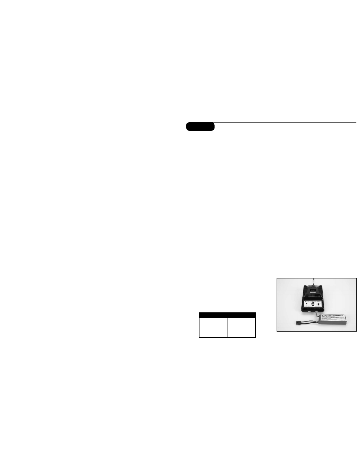
Charging the Aircraft Battery
Your T-28D comes with a DC balancing charger and 3S
Li-Po battery. You must charge the included Li-Po battery
pack with a Li-Po specific charger only (such as the
included charger). Never leave the battery and charger
unattended during the charge process. Failure to follow
the instructions properly could result in a fire. When
charging, make certain the battery is on a heat-resistant
surface. It is recommended to charge the battery pack
while you are assembling the aircraft. The flight battery
will be required to confirm proper aircraft operation in
future steps.
DC Li-Po Balancing Charger Features
• Charges 2- to 3-cell lithium polymer battery packs
• Variable charge rates from 300mAh–2A
• Automatically detects incorrect cell count selection
• Simple single push-button operation
• LED charge status indicator
• LED cell balance indicator
• Audible beeper indicates power and charge status
• 12V accessory outlet input cord
Specifications
• Input power: 12V DC, 3A
• Charges 2- to 3-cell Li-Po packs with minimum
capacity of 300mAh
• Variable charge rates from 300mAh to 2 amps
3S 11.1V 1800mAh Li-Po Battery Pack
The ParkZone 3S Li-Po battery pack features a
balancing lead that allows you to safely charge your
battery pack when used with the included ParkZone Li-Po
balancing charger.
To Complete the Charging Process
1. Attach the input cord of the charger to the
appropriate power supply (12V accessory outlet),
or use the HBZ6513 (Alligator Clip input adapter for
12V) and attach to 12V DC power supply. Once
your charger has been correctly powered up, there
will be an approximate 3-second delay and then you
will hear an audible “beep” and the green (ready) LED
will flash.
2. Refer to the char t below to select the appropriate
charge rates:
300—400mAh 300mAh
500—1000mAh 500mAh
1000—1500mAh 1A
1500—2000mAh 1.5A
2000mAh + 2.0A
BATTERY CAPACITY
MAX. CHARGE RATE
Warning: Selecting a charge rate higher than 1x
battery capacity may cause a fire.
3. Select the proper number of cells that you will be
charging, either 2 or 3 cells.
4. Locate the safety charge lead on the battery pack.
The charge lead of a 3-cell Li-Po battery will plug
into the larger 4-pin port on the bottom right of the
charger. A 2-cell pack will need to plug into the 3-pin
port on the bottom left of the charger. Once the
battery is properly plugged into the correct port,
it will beep 3 times if it is a 3-cell, and twice if it is
a 2-cell pack. Once this is done, you are ready to
proceed to charge the battery pack.
5. Push the start button to begin the charging process.
Once this is done, the charger will make an audible
beep that matches the cell count, and then the red
(charge) LED will begin to flash. Do not adjust the
current once the charger has begun to charge.
Note: At times, the green LED may also flash during
the charging process, indicating that the charger is
balancing one or more of the cells at the same time it
is charging the battery pack. When this is occurring,
the red and green LEDs will both be flashing. It will not
always be necessary for the cells to be balanced.
6. When the battery pack is fully charged, you will hear
an audible beep for about 3 seconds, and the green
LED will be solid. Always unplug the battery from the
charger immediately upon completion. Failure to do
so could cause a fire.
Warning: Failure to use the proper charger for a
Li-Po battery can result in serious damage, and if left
charging long enough, will cause a fire. ALWAYS use
caution when charging Li-Po batteries.
Page 3

3
4
Step 2
Transmitter-Specific Binding Instructions
DX5e:
A. To bind your T-28D Trojan to the DX5e, plug the bind
plug into the Batt/Bind por t on the AR500 receiver.
B. Plug the battery into the ESC of the airplane. The
LED on the receiver will begin flashing.
C. Move the sticks and switches on the transmitter to
the desired failsafe positions (low throttle and neutral
control positions).
D. Pull and hold the Trainer Switch on the transmitter
while turning the transmitter on. Release the trainer
switch once the LEDs on the front of the transmitter
flash.
E. The LED on the receiver will go solid amber and the
system will connect after several seconds.
F. Remove and store bind plug in a safe place.
DX6i:
A. To bind your T-28D Trojan to the DX6i, plug the bind
plug into the Batt/Bind por t on the AR500 receiver.
B. Plug the battery into the ESC of the airplane. The
LED on the receiver will begin flashing.
C. Move the sticks and switches on the transmitter to
the desired failsafe positions (low throttle and neutral
control positions).
D. Pull and hold the Trainer Switch on the transmitter
while turning the transmitter on. Release the trainer
switch once the word BIND flashes on the LCD
screen on the front of the transmitter.
E. The LED on the receiver will go solid amber and the
system will connect after several seconds.
F. Remove and store bind plug in a safe place.
Transmitter and Receiver Binding
Binding is the process of programming the receiver of
the control unit to recognize the GUID (Globally Unique
Identifier) code of a single specific transmitter. It will be
necessary for you to ‘bind’ your chosen Spektrum DSM2
technology equipped transmitter to the receiver for
proper operation.
The transmitter you select must be a DSM2 full
range (high power) Tx. The following is a list of
some of the Spektrum DSM2 equipped full range
transmitters and modules that will bind to the receiver of
the T-28D Trojan:
Spektrum DX5e JR X9303 2.4
Spektrum DX6i JR 12X 2.4
Spektrum DX7/DX7SE EFLH1056
All SPM Module systems
The following steps outline the binding process:
• Confirm the process of entering the bind mode for
your chosen transmitter by reviewing the instruction
manual included with the transmitter.
• Make sure the flight battery is disconnected from the
receiver unit and the transmitter is turned off.
• Plug the bind plug into the Batt/Bind port on the
AR500 receiver.
• Plug the flight battery into the battery lead of the
ESC. The LED on the receiver unit will begin flashing.
Note: NEVER plug the balance lead of the battery
directly into the receiver. This will cause damage to the
receiver and battery.
• After verifying the LED is flashing on the receiver,
follow the steps that allow your chosen transmitter to
enter bind mode.
• If you entered bind mode correctly, you will see a
solid LED approximately 5–10 seconds later on the
receiver. You should now be bound to the transmitter,
and have full control and function.
• Remove and store bind plug in a safe place.
If you encounter any problems, repeat the binding
process again, see the troubleshooting guide or call the
Horizon Support Team at 1-877-504-0233.
DX7 (includes DX7se):
A. To bind your T-28D Trojan to the DX7, plug the bind
plug into the Batt/Bind por t on the AR500 receiver.
B. Plug the battery into the ESC of the airplane. The
LED on the receiver will begin flashing.
C. Move the sticks and switches on the transmitter to
the desired failsafe positions (low throttle and neutral
control positions).
D. Press the bind button on the back of the transmitter
while turning the transmitter on. The bind button on
the back of the transmitter will flash. Release the
button after 2–3 seconds.
E. The LED on the receiver will go solid amber and the
system willconnect after several seconds.
F. Remove and store bind plug in a safe place.
X9303:
A. To bind your T-28D Trojan to the X9303, plug the
bind plug into the Batt/Bind port on the AR500
receiver.
B. Plug the battery into the ESC of the airplane. The
LED on the receiver will begin flashing.
C. Move the sticks and switches on the transmitter to
the desired failsafe positions (low throttle and neutral
control positions).
D. Press the bind button on the back of the transmitter
while turning the transmitter on. The bind button on
the back of the transmitter will flash. Release the
button after 2–3 seconds.
E. The LED on the receiver will go solid amber and the
system will connect after several seconds.
F. Remove and store bind plug in a safe place.
12X:
A. To bind your T-28D Trojan to the 12X, plug the bind
plug into the Batt/Bind por t on the AR500 receiver.
B. Plug the battery into the ESC of the airplane. The
LED on the receiver will begin flashing.
C. Move the sticks and switches on the transmitter to
the desired failsafe positions (low throttle and neutral
control positions).
D. Press the black bind button on the back of the
transmitter while turning the transmitter on. Release
the button after 2–3 seconds.
E. The LED on the receiver will go solid amber and the
system will connect after several seconds.
F. Remove and store bind plug in a safe place.
Transmitter Control Identification
Note: Each time before you fly you should ALWAYS turn
the transmitter on before connecting the flight battery
to the receiver unit. After each flight, be sure that you
always disconnect the flight battery from the receiver
unit before powering the transmitter of f.
Additional Binding Information
Prior to each flight, you should ensure that you power on
your transmitter and wait about five seconds before you
plug the flight battery into the receiver. Doing this allows
time for the transmitter to scan and secure two open
frequencies. If the flight battery is plugged in too quickly
and the link is missed, it may not allow the receiver to
connect to the transmitter. If this occurs, simply leave
the transmitter on and then disconnect and reconnect the
flight battery.
Note: If using a Futaba transmitter with a module, it
may be necessary to reverse the throttle channel.
Page 4
5
6
Step 3 Step 4
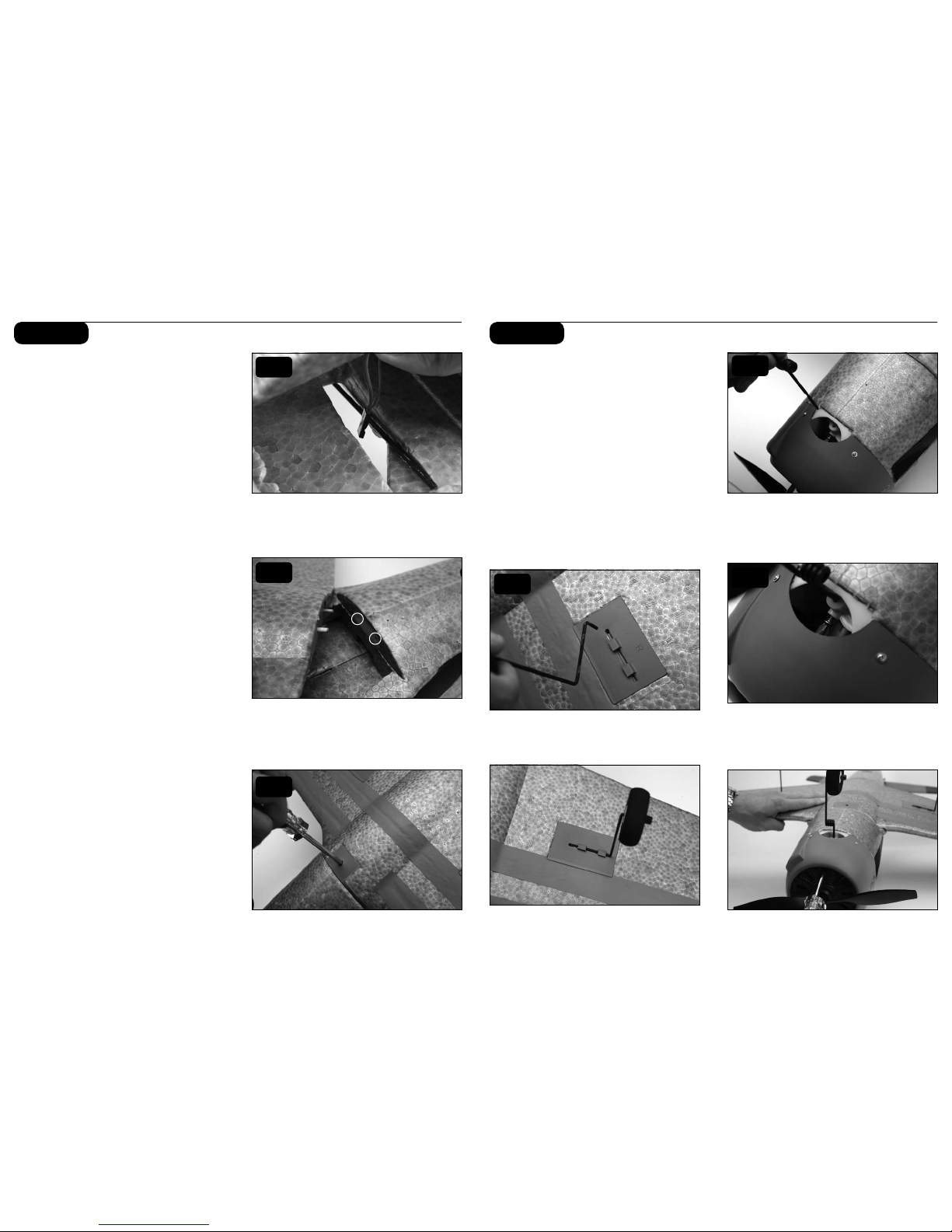
Attaching the Wing
In order to attach the wing of your T-28D, please follow
these simple instructions:
1. Locate the included wing-securing screw.
2. Turn over the fuselage so you are looking at the
bottom. Do the same with the wing.
3. Connect the aileron leads to the pre-installed
Y-harness, noting proper orientation. Route the
Y-harness lead through the access hole in the bottom
of the fuselage.
4. Carefully align the two locator pins on the front of
the wing into the two small holes in the front of the
fuselage.
5. Slide the aileron leads inside the fuselage so that
they will not become pinched in between the wing
and the fuselage when securing the wing.
6. Slide the bottom of the leading edge of the wing into
the fuselage as shown, making certain it is perfectly
centered. This must be done correctly in order to
allow the screw to thread into the fuselage. Once you
are certain the wing is centered, tighten the screw to
secure the wing.
7. The wing is correctly installed when no gap exists
between the wing and fillet.
8. Gently pull up on the rear of the canopy hatch to
remove and set aside.
9. Plug the Y-harness lead into one of the AIL ports of
the Spektrum AR500 receiver.
Installing the Landing Gear
1. Install the main landing gear by inserting it into the
locator hole in the wing. Swivel the landing gear
toward the retaining clips and gently snap into place.
2. Insert the nose gear into the steering assembly
on the underside of the cowl with the flat spot
facing forward.
3. Align the retaining screw with the flat spot on the
cowl. The retaining screw should be visible through
the front of the cowl.
4. Using a Phillips screwdriver, tighten the retaining
screw. The retaining screw should be accessible
through the front of the cowl, however, you may
choose to remove the cowl for easier access.
5. Reposition the T-28D so that it is resting on the
landing gear.
3
4
6
2
4
1
Page 5

7
8
Step 5 Step 6
Attaching the Horizontal Stabilizer
1. Locate the horizontal stab of the tail.
2. Slide tail in allotted space of fuse, making sure
the control horn installed into the horizontal tail will
properly align with pushrod and clevis exiting the
back of the fuse.
3. When you are certain the tail is centered correctly
and in the right place, use the tape provided to
properly secure the tail to the fuselage as shown.
Use the tape on the top and bottom of each side of
the tail (total of 4 applications).
4. Turn on the transmitter and plug in the flight battery.
Make sure the trim levers are centered and the left
stick is in the full down position.
5. Locate the clevis and rod exiting the right side of the
fuselage, and attach the clevis to the control surface
as shown.
6. Make any trim adjustments as necessary prior to
flight (see Step 10).
Note: To make trim adjustments to the horizontal
stabilizer:
a. Turn on radio transmitter.
b. Plug in fully charged battery into fuse.
c. Use the elevator trim of the radio by moving up or
down to center the tail at neutral when the gimbal is
also at neutral. If these changes are not sufficient,
center the transmitter elevator trim lever, then
remove the clevis from the control surface and
turn clevis in or out as needed to move the control
surface back to neutral.
Warning: Always keep hands and all objects away from
the propeller in case the motor is engaged. A moving
propeller can cause severe injury and/or damage.
Replacing the Propeller
1. Loosen prop hub by inser ting a hex driver through
the prop hub. Remove the prop hub and propeller.
2. Slide the new propeller on. Make certain the
numbers on the prop (9.5 x 7.5 for 2 blade) are
visible from the front.
3. Replace the prop hub and tighten it securely.
2
3
5
Page 6

9
10
Step 7
Range Checking your Radio System
After you have finished the final assembly, it is
time to range check the radio system within the
T-28D Trojan BNF.
Prior to each flying session
• Turn on the transmitter prior to plugging in the flight
battery. With the airplane on the ground and motor
running, you should walk away approximately 100
feet and still have full control of all functions while
following the specific range test feature of your
DSM2 transmitter. If this is not the case, do not
fly! Call Product Support at 1-877-504-0233.
• Always make sure that all controls are functioning per
the transmitter input that you are giving. This includes
ailerons, rudder, elevator and throttle.
• Always make sure you have fully charged the
transmitter batteries.
• Always remove the flight battery from the
airplane when you are done flying, or when you
are on the way to the flying field.
Flying
Always choose a wide-open space for flying your
ParkZone T-28D Trojan BNF. It is ideal for you to fly at
an AMA sanctioned flying field. If you are not flying at
an AMA approved site, always avoid flying near houses,
trees, wires and buildings. You should also be careful to
avoid flying in areas where there are many people, such
as busy parks or schoolyards. Always follow
local ordinances. We recommend only flying your Trojan in
light winds.
Prior to each flight
• Always make sure your T-28D Trojan BNF is properly
trimmed.
• Always make sure the receiver, ESC, and battery are
properly secured.
• Always verify the propeller is on securely.
• Always ensure the servo reversing switches on the
transmitter are set correctly.
• Always verify the dual rates switch is set at where
you plan on flying. We recommend LOW rates for
your initial flying. The T-28D Trojan BNF is VERY
maneuverable on high rates and requires a lot of
experience to handle properly.
Center of Gravity Location
The center of gravity on your T-28D Trojan should be
located approximately 2-1/2” behind the leading edge
of the wing, when measured against the fuselage. This
CG location has been determined with the ParkZone
1800mAh 11.1V Li-Po battery installed.
Fly in this area
(upwind of pilot)
Stand here
600 feet
WIND
Control Surface Travel Information
High Rate Low Rate
Aileron: 1/2 inch (13mm) 3/8 inch (9.5mm)
Elevator: 5/8 inch (16mm) 1/2 inch (13mm)
Rudder: 7/8 inch (22mm) 5/8 inch (16mm)
Step 8
Control Direction Test
1. Move the elevator stick on the transmitter forward
and aft to check elevator pitch control. When
the stick is pushed forward, the elevator should
move down.
2. When the elevator stick is moved aft the elevator
should move up.
3. Move the aileron stick left and right to check aileron
roll control. When the stick is pushed to the left,
the left aileron should move up and the right aileron
should move down.
4. With the aileron stick pushed right, the right
aileron should move up and the left aileron should
move down.
5. Move the rudder stick left and right to check yaw
control. When the stick is pushed to the right the
rudder should also move to the right (if viewed from
behind the airplane).
6. With the rudder stick pushed to the left, the
rudder should move to the left (if viewed from behind
the airplane).
If at any time during the test the controls respond in
the opposite direction, it may be necessary to reverse/
change the direction of operation of the flight controls.
Follow your transmitter instructions to change the
direction of the various flight controls.
Step 9
1
2
3
4
5
6
Page 7

11
12
30-Amp Pro Switch-Mode BEC Brushless
Controller
Your T-28D Trojan BNF comes out of the box with the
E-flite 30-Amp Pro Switch-Mode BEC Brushless Controller.
This controller has been designed for use in radio control
aircraft and is designed to support motor currents up
to 30 amps continuous, and a 5-volt Switch-Mode BEC
circuit capable of 700mAh continuous current on any
recommended input voltage with a 3- to 4-cell Li-Po
battery. It is suitable to use with most radio brands.
If you intend to fly your T-28D Trojan BNF stock, then
there is no need to program your ESC. It comes installed
with the default settings. If you intend to re-program the
ESC, we strongly recommend removing the propeller
first in order to keep it from spinning if the motor is
accidentally engaged.
Note: ALWAYS assume the motor and the propeller
are live. ALWAYS keep clear of the propeller at all
times. The high rpm of the brushless motor can cause
severe injury.
Features
• Up to 30-amp continuous current with proper airflow,
35-amp peak
• 5-volt Switch-Mode BEC circuit capable of
700mAh continuous current on any recommended
input voltage
• Drives up to 5 analog or 4 digital sub-micro servos
with the BEC
• 3S-4S Li-Po or 9- to 12-cell Ni-MH/Ni-Cd input voltage
• Programmable motor braking
• Safe power-arm mode prevents accidental starts
• Programmable low voltage cut-off with settings for
3S Li-Po (9.2V), 4S Li-Po (12V) or 74% of battery
starting voltage
• Programmable soft start for helis and airplanes
• Auto motor shutdown if signal is lost or there is
interference
• Programmable timing - 5 user-selectable ranges for
use with a larger variety of brushless motors
• Heli mode for star ting the motor with a low
speed ratio
• Optional RS232 Serial Link available for programming
(EFLARS232)
• Pre-wired connectors - E-flite EC3 connectors on
battery input and 3.5mm female gold bullets on
motor output leads
Using the 30-Amp Pro Switch-Mode BEC
Brushless Controller
This controller is very simple to use, and for safety, will
not arm the motor until the throttle stick has been held
in the Idle/Off position for more than 1 second. The
controller will indicate the soft cutof f voltage setting
every time you plug the battery in by first emitting a
low, long tone, to indicate star tup. Depending on the
selected cutoff voltage (default is 74%), you will then
hear the respective number of medium length mid tones
to indicate the cell count or a musical tone for the 74%
cutoff, helping you to confirm the setting before every
flight. Proper air cooling is required during flights so
the ESC should be placed in an area where air flows over
the controller.
Connecting the ESC to the Motor
The three wires from the motor connect to the three
female gold bullet connectors on the ESC. The order of
connection to the motor is not important; any motor wire
can be plugged into any connector. If the motor runs
backwards, you can simply unplug and switch any two of
the motor wire plugs connected to the ESC.
Mounting the ESC
Choose a location that has good airflow and offers good
protection. Do not cover the side with the flat heat shield
with hook and loop or tape as this will greatly reduce its
effectiveness. Mount the ESC with a combination of hook
and loop, 2-sided foam tape and/or tie wraps.
Starting Your Power System
1. Turn on your transmitter and ensure the position of
the throttle stick is set to Idle/Off.
2. Plug the battery pack into the controller. You will
hear 1 low long tone to indicate startup, then the
Step 10
respective number of medium-length mid tones to
indicate the cell count or a musical tone for the 74%
cutoff, followed by 3 rising tones to indicate the
controller is armed.
3. When you move the throttle stick upward, the motor
will run. Continue to move the throttle stick upward
to the full throttle (high) position, and the motor will
run faster. When the throttle stick goes below the
start-up position, the motor will stop running.
4. Check servo motion as part of your preflight check.
It is very important to make sure linkages are freemoving with no binding.
Remember, when in the programming mode:
Full Throttle = Stick Up
Idle = Stick Down
5. The default settings (from the package) for your
E-flite 30-Amp Pro ESC are as follows:
• Voltage cutoff set at 74%
• Brake set to Of f
• Timing set at 15 degrees
• Throttle Input Range set at 1.2ms to 1.8ms
• Start-up Rate (Acceleration Delay) set at 0.25
seconds
• PWM Frequency set at 8KHz
• Operating Mode set to normal (airplane)
Entering the Programming Mode
1. With the battery disconnected from the controller,
and the transmitter turned on, first move the throttle
stick to full throttle (>1.7ms) position. Leave it in
this position and then connect the battery to the
controller.
2. Wait for 5 seconds, and the ESC will give two
sets of fast ringing tones to indicate you have
successfully entered the programming mode.
3. Once you hear these tones, move the stick to center
(between 1.4 and 1.7ms) for 5 seconds, and the
controller will beep 1 time, indicating you are now in
Menu 1.
4. The controller will now wait 5 seconds for you to
make your selection; your programming options are
either full throttle (>1.7ms) or idle (<1.3ms).
5. When you have made a valid selection, the control
will beep once with a lower tone, and you can move
the stick back to center for the next menu item (2
beeps, 3 beeps and so on). If you do not make a
selection within 5 seconds, the controller will move
to the next menu item.
6. If you want to make changes in the programming
menus (see specific instructions below) move the
throttle stick to full throttle (>1.7ms) position. You
will have 5 seconds to make your selection.
7. If you want to advance to the next menu, allow the
programming to skip to the next menu after the 5
seconds have expired.
Programming Menu 1 – Voltage Cutoff
Use this option to set the voltage at which the controller
will shut down the motor to prevent damage to your
battery when it reaches the cutof f voltage. You will know
your battery pack has reached auto cutoff when you hear
the motor “pulse” repeatedly.
1. Move the throttle stick to full throttle (>1.7ms)
position to make changes to the voltage cutoff
programming.
a. To select 3-cell low voltage cutoff – You will hear
3 short beeps. Move the throttle stick to center
(between 1.4 and 1.6ms). The controller will beep 2
times, indicating you have set the program selection
or leave in full throttle for 5 seconds to advance to
the next selection.
b. To select 4-cell low voltage cutoff – You will hear
4 short beeps. Move the throttle stick to center
(between 1.4 and 1.6ms). The controller will beep 2
times, indicating you have set the program selection
or leave in full throttle for 5 seconds to advance to
the next selection.
c. To select 5-cell low voltage cutoff – You will hear
5 short beeps. Move the throttle stick to center
(between 1.4 and 1.6ms). The controller will beep 2
times, indicating you have set the program selection
or leave in full throttle for 5 seconds to advance to
the next selection.
d. To select 6-cell low voltage cutoff – You will hear
6 short beeps. Move the throttle stick to center
(between 1.4 and 1.6ms). The controller will beep 2
times, indicating you have set the program selection
or leave in full throttle for 5 seconds to advance to
the next selection.
e. To select 74% cutoff – You will hear 7 shor t beeps.
Move the throttle stick to center (between 1.4 and
1.6ms). The controller will beep 2 times, indicating
you have set the program selection or leave in
full throttle for 5 seconds to advance to the first
selection again.
Page 8

13
14
IMPORTANT NOTE ABOUT 74% CUTOFF: This
option will activate the soft cutoff at 74% of star tup
voltage or 9.2V, whichever is higher. For example,
if your pack measures 16.8 volts at startup, then
the soft cut will occur at 12.4 volts. The 74% cutoff
option will check the startup voltage every time you
plug the battery into the controller, so beware of
using partially charged packs, as the system cannot
protect your Li-Po batteries if you are using the 74%
cutoff and connect a partially charged pack. You will
know your battery pack has reached soft auto cutoff
when you hear the motor “pulse” repeatedly. We
recommend you land your model as soon as you
hear the motor pulse (indicating the pack voltage has
dropped to the cutoff voltage level) to prevent overdischarge of the Li-Po battery pack, and to prevent
sudden power loss.
Programming Menu 2 – Brake Type
The default setting is Brake Off. This option gives you the
choice to have the ESC stop the propeller during flight
(Brake On) or allow it to windmill (Brake Off). Use the
Brake On options for folding propellers.
1. Move the stick to center (between 1.4 and 1.6ms)
for 5 seconds, and the controller will beep 2 times,
indicating you are now in Menu 2.
2. Move the throttle stick to full throttle (>1.7ms)
position to make changes to the Brake Type
programming.
a. To select No Brake/Brake Off – You will hear
1 short beep. Move the throttle stick to center
(between 1.4 and 1.6ms). The controller will beep
2 times, indicating you have set the program
selection or leave in full throttle for 5 seconds to
advance to the next selection.
b. To select Soft Brake – You will hear 2 shor t beeps.
Move the throttle stick to center (between 1.4
and 1.6ms). The controller will beep 2 times,
indicating you have set the program selection or
leave in full throttle for 5 seconds to advance to
the next selection.
c. To select Medium Brake – You will hear 3 shor t
beeps. Move the throttle stick to center (between
1.4 and 1.6ms). The controller will beep 2 times,
indicating you have set the program selection or
leave in full throttle for 5 seconds to advance to
the next selection.
d. To select Hard Brake – You will hear 4 short
beeps. Move the throttle stick to center (between
1.4 and 1.6ms). The controller will beep 2 times,
indicating you have set the program selection or
leave in full throttle for 5 seconds to advance to
the first selection again.
Programming Menu 3 – Timing
The default setting is 15 degrees. As a general rule,
lower pole count motors use lower timing and higher
pole count motors use higher timing. Please refer to your
motor instructions and specifications for an indication of
the number of poles.
LowTimingAdvance
Timing Degrees – 5 & 10
Motor Poles – 2 to 4
Expected Performance – Good balance of power and
efficiency
Motor Poles – 6 or more
Expected Performance – Best efficiency and run time
(lowest power)
StandardTimingAdvance
Timing Degrees – 15 & 20
Motor Poles – 6 to 12
Expected Performance – Good balance of power and
efficiency
Motor Poles – 14 or more
Expected Performance – Best efficiency and run time
(lowest power)
HighTimingAdvance
Timing Degrees – 25
Motor Poles – 12
Expected Performance – Highest power, less
efficiency
Motor Poles – 14 or more
Expected Performance – Good balance of power and
efficiency
1. Move the stick to center (between 1.4 and 1.6ms)
for 5 seconds, and the controller will beep 3 times,
indicating you are now in Menu 3.
2. Move the throttle stick to full throttle (>1.7ms)
position to make changes to the Timing
programming.
a. To select 5 Degrees – You will hear 1 short beep.
Move the throttle stick to center (between 1.4 and
1.6ms). The controller will beep 2 times, indicating
you have set the program selection or leave in
full throttle for 5 seconds to advance to the next
selection.
b. To select 10 Degrees – You will hear 2 short
beeps. Move the throttle stick to center (between
1.4 and 1.6ms). The controller will beep 2 times,
indicating you have set the program selection or
leave in full throttle for 5 seconds to advance to
the next selection.
c. To select 15 Degrees – You will hear 3 short
beeps. Move the throttle stick to center (between
1.4 and 1.6ms). The controller will beep 2 times,
indicating you have set the program selection or
leave in full throttle for 5 seconds to advance to
the next selection.
d. To select 20 Degrees – You will hear 4 short
beeps. Move the throttle stick to center (between
1.4 and 1.6ms). The controller will beep 2 times,
indicating you have set the program selection or
leave in full throttle for 5 seconds to advance to
the next selection.
e. To select 25 Degrees – You will hear 5 short
beeps. Move the throttle stick to center (between
1.4 and 1.6ms). The controller will beep 2 times,
indicating you have set the program selection or
leave in full throttle for 5 seconds to advance to
the first selection again.
Programming Menu 4 – Throttle Input Range
(PWM)
The default setting is 1.2ms to 1.8ms and should work
with most radio systems. This option allows for proper
throttle input with many different radio systems. However,
some radios have a wider output range, and may give
a more linear response with the 1.1ms to 1.9ms range.
If you feel there is too much “dead” area in the stick
movement near full throttle, try adjusting the end points
in your radio, or change to the wider input range. Be
aware that if these settings are not correct, it may be
impossible to arm the controller.
1. Move the stick to center (between 1.4 and 1.6ms)
for 5 seconds, and the controller will beep 4 times,
indicating you are now in Menu 4.
2. Move the throttle stick to full throttle (>1.7ms)
position to make changes to the Throttle Input
Range programming.
a. To select 1.2ms to 1.8ms – You will hear 1 short
beep. Move the throttle stick to center (between
1.4 and 1.6ms). The controller will beep 2 times,
indicating you have set the program selection or
leave in full throttle for 5 seconds to advance to
the next selection.
b. To select 1.1ms to 1.9ms – You will hear 2 short
beeps. Move the throttle stick to center (between
1.4 and 1.6ms). The controller will beep 2 times,
indicating you have set the program selection or
leave in full throttle for 5 seconds to advance to
the first selection again.
Programming Menu 5 – Start-Up Rate
The default setting is 0.25 seconds. The start-up rate
is the time it takes to reach maximum motor speed.
Changing the setting to 1 second can be useful with
power-fragile gear boxes.
1. Move the stick to center (between 1.4 and 1.6ms)
for 5 seconds, and the controller will beep 5 times,
indicating you are now in Menu 3.
2. Move the throttle stick to full throttle (>1.7ms)
position to make changes to the Start-up Rate
programming.
a. To select .25 second – You will hear 1 shor t beep.
Move the throttle stick to center (between 1.4 and
1.6ms). The controller will beep 2 times, indicating
you have set the program selection or leave in
full throttle for 5 seconds to advance to the next
selection.
b. To select 1 second – You will hear 2 shor t beeps.
Move the throttle stick to center (between 1.4 and
1.6ms). The controller will beep 2 times, indicating
you have set the program selection or leave in
full throttle for 5 seconds to advance to the first
selection again.
Programming Menu 6 – PWM Switching
Frequency
The default setting is 8KHz, which should be acceptable
for most motors. If you have a low or very low
inductance motor and know you need to use a higher
PWM Frequency (refer to the manual included with the
motor), then you can change the setting. Otherwise, we
recommend leaving the default setting.
1. Move the stick to center (between 1.4 and 1.6ms)
for 5 seconds, and the controller will beep 6 times,
indicating you are now in Menu 6.
2. Move the throttle stick to full throttle (>1.7ms)
position to make changes to the PWM Switching
Frequency programming.
a. To select 8KHz PWM Frequency – You will hear
1 short beep. Move the throttle stick to center
(between 1.4 and 1.6ms). The controller will beep
2 times, indicating you have set the program
selection or leave in full throttle for 5 seconds to
advance to the next selection.
b. To select 16KHz PWM Frequency – You will hear
2 short beeps. Move the throttle stick to center
(between 1.4 and 1.6ms). The controller will beep
2 times, indicating you have set the program
Page 9

15
16
Troubleshooting
The controller will beep more quietly than normal if the
input voltage is below the cutoff voltage when the battery
is connected. Check the voltage of the battery pack to
see if it is correct (charged), or the programmed cutoff
setting if the input voltage is set incorrectly for the
voltage of the pack being used.
If you have trouble arming the controller (and the throttle
trim has been set to minimum), enter the programming
mode and try changing the setting to 1.1ms–1.9ms
in Programming Menu 4 to see if it helps correct the
problem. If it is a computer radio, you may alternatively
increase high and low throttle ATV (endpoint) percentages.
Note: Increasing the high ATV will not have a
consequence on arming issues, only low ATV.
Some transmitters, including all Futaba transmitters, will
require the throttle channel to be “reversed” for proper
operation.
selection or leave in full throttle for 5 seconds to
advance to the next selection.
c. To select 32KHz PWM Frequency – You will hear
3 short beeps. Move the throttle stick to center
(between 1.4 and 1.6ms). The controller will beep
2 times, indicating you have set the program
selection or leave in full throttle for 5 seconds to
advance to the first selection again.
Programming Menu 7 – Operating Mode
The default setting is set to Normal (airplane) Mode,
which is limited to a start-up rate of 0.25 or 1 second.
Alternatively, the Heli Mode can be selected which
reduces the start-up rate to 5 seconds for the first
start-up and any star t-up after the motor/ESC has been
stopped for more than 5 seconds. This helps to prevent
damaging the motor, gears or any other components
from an abrupt start-up when none of the parts are
moving. Any time the motor/ESC has been stopped for
less than 5 seconds in Heli Mode, the start-up will be
immediate. This allows power to be applied immediately,
such as when aborting an auto-rotation attempt or for any
other reason, to help prevent a crash. Remember, you
must wait more than 5 seconds after stopping the motor/
ESC in order for the 5-second start-up to occur again.
1. Move the stick to center (between 1.4 and 1.6ms)
for 5 seconds, and the controller will beep 7 times,
indicating you are now in Menu 7.
2. Move the throttle stick to full throttle (>1.7ms)
position to make changes to the Operating Mode
programming.
a. To select Normal Mode – You will hear 1 shor t
beep. Move the throttle stick to center (between
1.4 and 1.6ms). The controller will beep 2 times,
indicating you have set the program selection or
leave in full throttle for 5 seconds to advance to
the next selection.
b. To select Heli Mode – You will hear 2 shor t beeps.
Move the throttle stick to center (between 1.4 and
1.6ms). The controller will beep 2 times, indicating
you have set the program selection or leave in
full throttle for 5 seconds to advance to the first
selection again.
Replacement Parts
Make sure that you keep your T-28D Trojan BNF flying. Replacement parts are available at your local hobby shop or from
Horizon Hobby (www.horizonhobby.com). Please try your local hobby shop first. By supporting them, they will be there
when you need them.
Item #: Description:
PKZ1011 Prop Adapter: T-28D
PKZ1012 Propeller: T-28D
PKZ1031 11.1V 1800mAh Li-Po Battery
PKZ1040 Variable Rate 2- to 3-cell DC Powered Balancing Li-Po Charger
PKZ1060 SV120 Servo (short lead): T-28D Elevator
PKZ1063 Servo Y-Harness: T-28D/3D2
PKZ1064 Metal Gear Set: DSV130M
PKZ1081 SV80 Servo (long lead): T-28D Ailerons
PKZ1090 DSV130M Servo (short lead): T-28D Rudder
PKZ4406 Main Landing Gear: T-28D
PKZ4407 Nose Gear Set: T-28D
PKZ4416 480 Outrunner Brushless Motor: T-28D
PKZ4418 Motor Mount
PKZ4422 Pushrods w/Clevis: T-28D
PKZ5003 Decal Sheet: T-28D
PKZ5013 Clear Canopy & Painted Pilot w/Pedestal: T-28D
PKZ5020 Painted Wing (No Servo): T-28D
PKZ5025 Horizontal Tail w/Accessories: T-28D
PKZ5026 Cowl: T-28D
PKZ5067 Painted Bare Fuselage: T-28D
EFLA1030 30-Amp Pro Switch-Mode BEC Brushless ESC
Optional Parts
Item #: Description:
PKZ1030 11.1V 2200mAh Li-Po Battery
SPMR5500 DX5e Mode 2 Full Range Transmitter
SPMR6600 DX6i Mode 2 Full Range Transmitter
Page 10

17
18
If you as the Purchaser or user are not prepared
to accept the liability associated with the use of
this Product, you are advised to return this Product
immediately in new and unused condition to the place of
purchase.
Law: These Terms are governed by Illinois law (without
regard to conflict of law principals).
Safety Precautions
This is a sophisticated hobby Product and not a toy. It
must be operated with caution and common sense and
requires some basic mechanical ability. Failure to operate
this Product in a safe and responsible manner could result
in injury or damage to the Product or other property.
This Product is not intended for use by children without
direct adult supervision. The Product manual contains
instructions for safety, operation and maintenance. It
is essential to read and follow all the instructions and
warnings in the manual, prior to assembly, setup or use,
in order to operate correctly and avoid damage or injury.
Questions, Assistance, and Repairs
Your local hobby store and/or place of purchase cannot
provide warranty support or repair. Once assembly, setup
or use of the Product has been started, you must contact
Horizon directly. This will enable Horizon to better answer
your questions and service you in the event that you may
need any assistance. For questions or assistance, please
direct your email to productsupport@horizonhobby.com,
or call 877.504.0233 toll free to speak to a service
technician.
Inspection or Repairs
If this Product needs to be inspected or repaired, please
call for a Return Merchandise Authorization (RMA). Pack
the Product securely using a shipping carton. Please note
that original boxes may be included, but are not designed
to withstand the rigors of shipping without additional
protection. Ship via a carrier that provides tracking and
insurance for lost or damaged parcels, as Horizon is
not responsible for merchandise until it arrives and is
accepted at our facility. A Service Repair Request is
available at www.horizonhobby.com on the “Support” tab.
If you do not have internet access, please include a letter
with your complete name, street address, email address
and phone number where you can be reached during
business days, your RMA number, a list of the included
items, method of payment for any non-warranty expenses
and a brief summary of the problem. Your original sales
receipt must also be included for warranty consideration.
Be sure your name, address, and RMA number are clearly
written on the outside of the shipping carton.
Warranty Inspection and Repairs
To receive warranty service, you must include your
original sales receipt verifying the proof-of-purchase
date. Provided warranty conditions have been met, your
Product will be repaired or replaced free of charge.
Repair or replacement decisions are at the sole discretion
of Horizon Hobby.
Non-Warranty Repairs
Should your repair not be covered by warranty the
repair will be completed and payment will be required
without notification or estimate of the expense unless
the expense exceeds 50% of the retail purchase cost.
By submitting the item for repair you are agreeing
to payment of the repair without notification. Repair
estimates are available upon request. You must include
this request with your repair. Non-warranty repair
estimates will be billed a minimum of ½ hour of labor.
In addition you will be billed for return freight. Please
advise us of your preferred method of payment. Horizon
accepts money orders and cashiers checks, as well as
Visa, MasterCard, American Express, and Discover cards.
If you choose to pay by credit card, please include your
credit card number and expiration date. Any repair left
unpaid or unclaimed after 90 days will be considered
abandoned and will be disposed of accordingly. Please
note: non-warranty repair is only available on electronics
and model engines.
United States
Electronics and engines requiring inspection or repair
should be shipped to the following address:
Horizon Service Center
4105 Fieldstone Road
Champaign, Illinois 61822
USA
All other Products requiring warranty inspection or repair
should be shipped to the following address:
Horizon Product Support
4105 Fieldstone Road
Champaign, Illinois 61822
USA
Please call 877-504-0233 or e-mail us at
productsupport@horizonhobby.com with any questions or
concerns regarding this product or warranty.
United Kingdom
Electronics and engines requiring inspection or repair
should be shipped to the following address:
Horizon Hobby UK
Units 1-4 Ployters Rd
Staple Tye
Harlow, Essex
CM18 7NS
United Kingdom
Please call +44 (0) 1279 641 097 or e-mail us at sales@
horizonhobby.co.uk with any questions or concerns
regarding this product or warranty.
Germany
Electronics and engines requiring inspection or repair
should be shipped to the following address:
Horizon Technischer Service
Hamburger Strasse 10
25335 Elmshorn
Germany
Please call +49 4121 46199 66 or e-mail us at
service@horizonhobby.de with any questions or concerns
regarding this product or warranty.
Warranty Period
Exclusive Warranty- Horizon Hobby, Inc., (Horizon)
warranties that the Products purchased (the “Product”)
will be free from defects in materials and workmanship at
the date of purchase by the Purchaser.
Limited Warranty
(a) This warranty is limited to the original Purchaser
(“Purchaser”) and is not transferable. REPAIR OR
REPLACEMENT AS PROVIDED UNDER THIS WARRANTY
IS THE EXCLUSIVE REMEDY OF THE PURCHASER. This
warranty covers only those Products purchased from
an authorized Horizon dealer. Third party transactions
are not covered by this warranty. Proof of purchase is
required for warranty claims. Further, Horizon reserves
the right to change or modify this warranty without notice
and disclaims all other warranties, express or implied.
(b) Limitations- HORIZON MAKES NO WARRANTY OR
REPRESENTATION, EXPRESS OR IMPLIED, ABOUT
NON-INFRINGEMENT, MERCHANTABILITY OR FITNESS
FOR A PARTICULAR PURPOSE OF THE PRODUCT. THE
PURCHASER ACKNOWLEDGES THAT THEY ALONE HAVE
DETERMINED THAT THE PRODUCT WILL SUITABLY MEET
THE REQUIREMENTS OF THE PURCHASER’S INTENDED
USE.
(c) Purchaser Remedy- Horizon’s sole obligation
hereunder shall be that Horizon will, at its option, (i)
repair or (ii) replace, any Product determined by Horizon
to be defective. In the event of a defect, these are
the Purchaser’s exclusive remedies. Horizon reserves
the right to inspect any and all equipment involved in
a warranty claim. Repair or replacement decisions are
at the sole discretion of Horizon. This warranty does
not cover cosmetic damage or damage due to acts of
God, accident, misuse, abuse, negligence, commercial
use, or modification of or to any part of the Product.
This warranty does not cover damage due to improper
installation, operation, maintenance, or attempted repair
by anyone other than Horizon. Return of any goods by
Purchaser must be approved in writing by Horizon before
shipment.
Damage Limits
HORIZON SHALL NOT BE LIABLE FOR SPECIAL,
INDIRECT OR CONSEQUENTIAL DAMAGES, LOSS OF
PROFITS OR PRODUCTION OR COMMERCIAL LOSS IN
ANY WAY CONNECTED WITH THE PRODUCT, WHETHER
SUCH CLAIM IS BASED IN CONTRACT, WARRANTY,
NEGLIGENCE, OR STRICT LIABILITY. Further, in no event
shall the liability of Horizon exceed the individual price of
the Product on which liability is asserted. As Horizon has
no control over use, setup, final assembly, modification or
misuse, no liability shall be assumed nor accepted for any
resulting damage or injury. By the act of use, setup or
assembly, the user accepts all resulting liability.
Page 11

19
20
Declaration of Conformity
(in accordance with ISO/IEC 17050-1)
No. HH20090520
Product(s): PKZ T-28D BL BNF
Item Number(s): PKZ5000
Equipment class: 1
The object of declaration described above is in
conformity with the requirements of the specifications
listed below, following the provisions of the European
R&TTE directive 1999/5/EC:
EN 301 489-1, 301 489-17
General EMC requirements for Radio equipment
Signed for and on behalf of:
Horizon Hobby, Inc.
Champaign, IL USA
May 20, 2009
Steven A. Hall
Vice President International Operations
and Risk Management
Horizon Hobby, Inc.Warranty Inspection and Repairs
Compliance Information for the European Union
Instructions for Disposal of WEEE by Users in
the European Union
This product must not be disposed of with other
waste. Instead, it is the user’s responsibility to
dispose of their waste equipment by handing
it over to a designated collection point for the
recycling of waste electrical and electronic
equipment. The separate collection and
recycling of your waste equipment at the time of disposal
will help to conserve natural resources and ensure that it
is recycled in a manner that protects human health and
the environment. For more information about where you
can drop off your waste equipment for recycling, please
contact your local city of fice, your household waste
disposal service or where you purchased the product.
Page 12

21
22
 Loading...