

Page 1
Charge-and-Fly™ Park Flyer
Super Decathlon BL
Instruction Manual
Wingspan: 35.4 in (900mm)
Overall Length: 25.3 in (640mm)
Weight: 16 oz (450 g)
Motor: PKZ 370-size outrunner brushless, 1500Kv
FM Radio System: ZX10 3 proportional channels
Battery: 7.4V 800mAh Li-Po
ParkZone® products are distributed exclusively by
Horizon Hobby, Inc.
4105 Fieldstone Road
Champaign, IL 61822
© 2008 Horizon Hobby, Inc.
Horizon Hobby UK
Units 1-4, Ployters Road
Staple Tye
Harlow, Essex
CM187NS
United Kingdom
Horizon Hobby Deutschland GmbH
Otto Hahn Str. 9a
25337 Elmshorn
Germany
parkzone.com
13803
Futaba is a registered trademark of Futaba Denshi Kogyo Kabushiki Kaisha
Corporation of Japan.
Velcro
®
is a registered mark of Velcro Industries, B.V., Netherlands.
Page 2
3
4
Congratulations on your purchase of the ParkZone®
Super Decathlon BL. Your Super Decathlon BL has
come with everything to get you in the air—all in one box.
You will only need to attach the wing and landing gear, as
well as charge the battery prior to ight.
We at ParkZone are committed to giving you the most
enjoyable ight experience you can have. In order to
have a safe and successful ight, we ask that you do not
y until you have read these instructions thoroughly.
The Super Decathlon BL comes with a fully proportional
3-channel FM radio system, providing full control of
throttle, elevator and rudder. If you are not experienced
at ying one of HobbyZone’s 3-channel aircraft, or any
other 3-channel radio controlled aircraft, we recommend
that you do not y this aircraft. If you still choose to y,
you will need to seek the help of an experienced radio
control pilot during your rst several ights. Crash
damage is not covered under the warranty.
The ParkZone Super Decathlon BL is equipped with
the exclusive ZX10 radio system which utilizes 10-bit,
1024-step processing for high-delity control. It uses a
6-channel FM receiver with industry-standard 3-wire
servos.
The ZX10 system also features dual rates, allowing you
to y how you feel most comfortable. Low rate limits
the travel of the control surfaces and offers smooth and
relaxing ight. High rate allows for full control at all times
for those craving the maximum performance of their
aircraft.
Introduction
Step 1 – Charging the Aircraft Battery
Step 2 – Installing the Transmitter Batteries
Step 3 – Installing the Landing Gear
Step 4 – Attaching the Wing
Super Decathlon BL
This charger uses unique circuitry that ensures an
accurate charge every time and protects your Li-Po
batteries from the dangers of overcharging. This
charger continually monitors the battery and
automatically stops charging when the battery is fully
charged. The balance charger will help avoid damaging
Li-Po cells.
DC Li-Po Balancing Charger Features:
• Charges 2-cell lithium polymer battery packs
• LED charge status indicator
• LED cell balance indicator
• 12V outlet power cord
You must charge the included Li-Po battery pack with a
Li-Po specic charger only (such as the included
charger). Never leave the battery and charger unattended during the charge process. Failure to properly follow
the instructions could result in a re. When charging,
make certain the battery is on a heat-resistant surface. It
is recommended to charge the Li-Po battery immediately,
as it will be used in future assembly steps.
1. Insert 8 new AA batteries (supplied) into the
transmitter, observing proper polarity.
2. Tur n the power switch on to ensure the batteries
have been installed correctly. Once this is
conrmed, turn the transmitter off.
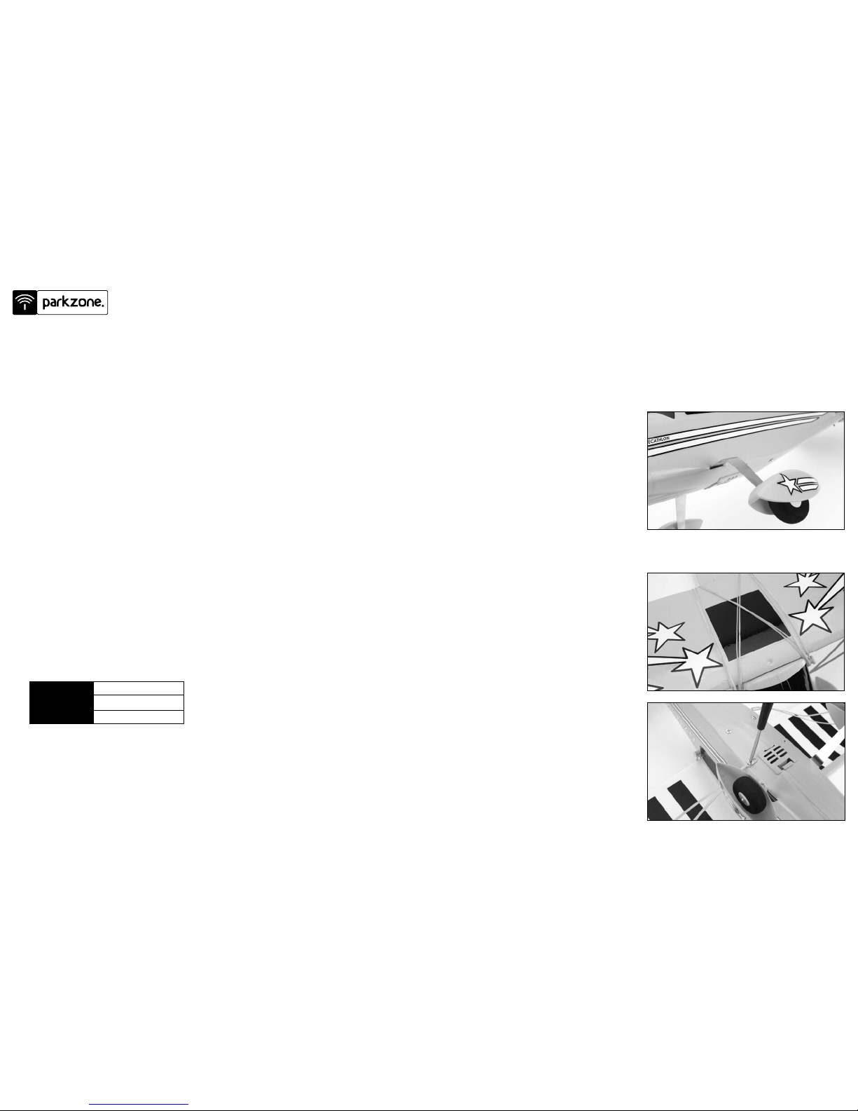
1. Locate the landing gear within the packaging.
2. Slide one half of the landing gear into the
allotted slot in the fuselage until it locks into
place. Slide the other half of the landing gear into
the fuselage as you have done with the previous
one. Look into the fuselage to make sure the two
gear halves are pressed in snug against the
center of the landing gear support.
3. Make sure both parts of the landing gear are
secure and properly in place. They should feel
snug inside the fuselage when attached properly.
1. Locate the wing and wing strut screws.
2. Place the wing on the top of the fuselage, making
certain it is centered properly. Attach the wing
with four rubber bands that are included. Stretch
two of the rubber bands from the front to the rear
attach points. Stretch the last two diagonally
across the middle to the attach points.
3. Attach the wing struts to the fuselage. Locate the
two small Phillips screws and attach the strut to
the fuselage as shown. Once the screw is
tightened into the fuselage, you can loosen it
slightly to allow the slack of the strut to be
adjusted as needed.
4. Make sure that prior to each ight the wing is
properly centered on the fuselage. If the wing
is not centered properly, it is impossible to have
correct ight.
Charging the Aircraft Battery
1. The 12V DC 2S Li-Po balancing charger provides a
charge current of .8 amps. The typical charge time
for the included 7.4V 800mAh Li-Po is
approximately 40 minutes to 1 hour.
2. Locate the balancing charge lead on the
battery pack. Connect the battery pack to the
charger. Charge through the balance lead on the
battery pack.
3. Connect the charger to the 12V power outlet in
your automobile. Please note that some 12V
outlets require your vehicle to be running for the
outlet to be operational. It is not recommended to
charge batteries while the vehicle is in motion. The
LED will continually blink while the battery charges.
4. Charging is nished when the LED indicator
glows steadily.
Note: Damage to the charger and battery will occur if
you exceed the recommended maximum charge rate.
For charging outside of the vehicle, you may wish
to purchase a 12V DC extension with alligator leads
(HBZ6513). This will allow you to connect the charger
to a 12V battery or power supply.
BATTERY CAPACITY
MAX. CHARGE RATE
CHARGE TIME
800mAh 7.4V 2S Li-Po
.8 amps
60 minutes
Page 3
5
6
Step 5 – Motor Test
Step 6 – Tail Control Test
Step 6 – Tail Control Test (continued)
Step 7 – Control Surface Adjustments
1. Make sure the throttle slider is in the
OFF position.
2. Turn on the transmitter.
3. Remove the battery door from the bottom of
the fuselage.
4. Plug ight battery into the ESC inside of
the fuselage. The ESC has been preset for 2S
Li-Po low voltage cutoff.
5. Secure the battery inside the fuselage cavity and
replace the battery door.
6. Your Super Decathlon BL has a built-in
throttle-arming feature which needs to “see” the
throttle slider in the OFF position before it will
spin the propeller.
Warning: Keep everything clear of the propeller before starting the control test in the event that you accidentally
turn on the motor.
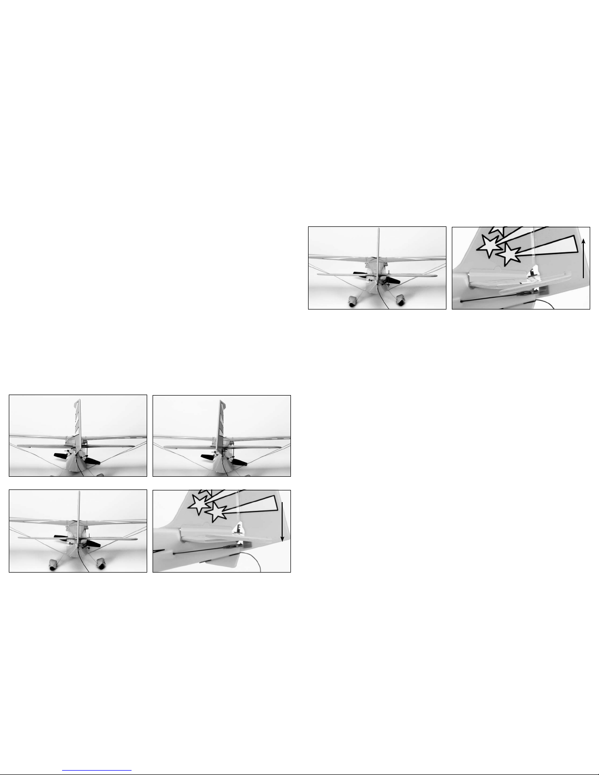
1. Be certain that the throttle slider is in the OFF position. Make certain both trim levers are centered.
2. Move the stick from side to side. The rudder should move per your transmitter input.
3. Move the stick full forward. When this is done, the elevator control surface should move down.
4. Pull the stick back and the elevator control surface should move up.
5. If your airplane is not responding correctly to the transmitter input, do not fly. Some correction is needed.
Call the Horizon Support Team at 1-877-504-0233.
6. When the test is complete, be sure to disconnect the ight battery rst, then turn off the transmitter. This
should be done each time you turn off the airplane.
Note: It is very important to make sure that the control surfaces (rudder and elevator) are at 0 degrees when the
transmitter control stick and trim levers are centered.
1. Any changes necessary to bring both the rudder
and elevator to neutral (0 degrees) when the
transmitter stick is centered should be possible
using the trim levers.
2. If you nd this is not the case, do not y until this
has been corrected.
3. If corrections are needed, you may have to adjust
the length of the pushrod by removing the clevis
from the control surface horn and turning the
plastic clevis as necessary. Prior to doing this,
make certain the trim levers and stick are centered.
If you have any questions regarding these
adjustments, please contact the Horizon Support Team
at 1-877-504-0233.
Caution: Make sure that you, as well as loose
objects and hair, are away from the propeller at
all times.
Grasp the rear of the fuselage with the nose of the
Super Decathlon facing away from you. Advance
the throttle forward and the propeller should spin
at a high speed. The throttle-arming feature will
need to be activated each time the battery is
plugged into the airplane.
7. When nished with the motor test, continue to the
Tail Control Test on the next page.
Note: It is important to always turn on the transmitter
prior to plugging in the flight battery. Plugging in the
flight battery first may cause undesired operation due
to interference, potentially resulting in damage to the
aircraft or personal injury.
Page 4

7
8
Step 8 – Flying
Step 9 – Choose a Calm Day
Step 10 – Range Test
Step 11 – Seek Assistance from an Experienced Radio Control Pilot
Choose a Large, Open Fying Site
• A large, open grassy eld is recommended to y
your Super Decathlon BL. The Super Decathlon
BL covers ground quickly. The larger the eld, the
better.
• It is essential to have a minimum of 300 feet of clear
space in all directions from the pilot. Ignoring this
direction could result in a yaway airplane.
• Make certain that you do not y near trees,
buildings or other areas that can restrict your view
or interfere with your ying.
• Always keep the plane upwind from you to avoid
yaways. This is essential.
You want to y. However, you need to make sure that you
y in the conditions that will allow you to have the best
success. This is when there is little to no wind (less than
7 mph).
To check wind conditions:
1. Tie the included red ribbon to the transmitter
antenna.
2. Hold the transmitter antenna so that it is parallel to
the ground and note how much the ribbon moves
in the wind. If the ribbon hangs down, conditions
are right to y. However, if the angle between the
antenna and the ribbon is less than 20 degrees, it
is too windy to y.
You will need two people to perform the range test: one
to hold the plane and the other to give the transmitter
input.
Warning: The person holding the plane should hold
it in a way so the propeller does not come into
contact with anything loose on his/her clothing
or body.
1. One person holds the transmitter, while the other
person walks 100 paces away with the airplane.
2. Be sure the throttle slider is in the OFF position.
3. Extend the transmitter antenna completely and
turn the transmitter on.
4. Plug the airplane battery into the fuselage and
replace the battery door.
5. As soon as the throttle slider is advanced, the
propeller should spin quickly.
VERY IMPORTANT: The 3-channel control system is
designed for the experienced radio control pilot and is
not intended for the rst-time ier. It is best to have
HobbyZone Zone 2 experience. First-time pilots of the
ParkZone Super Decathlon BL should seek the
assistance of an experienced RC ier until the additional
third channel, pitch control, has been competently
mastered. Crash damage is not covered under
the warranty.
Important: Initial flights should always be done with
the airplane in low rate mode.
6. As the rst person moves the transmitter controls
at the same time, the other person watches to be
sure the airplane’s motor and tail controls operate
smoothly.
100 paces
Page 5

9
10
Step 12 – Hand Launching the Super Decathlon BL
Step 13 – Runway Takeoff
Step 14 – Flying
1. Make certain that the aircraft battery is
fully charged.
2. Turn on the transmitter.
3. Plug in the ight battery.
4. Arm the motor and test the motor controls.
5. While holding the transmitter in one hand, push the
throttle to full on (up) with your thumb.
6. Take a couple of steps back and launch directly
into the wind. Keep the wings level. Use medium
force; do not throw it up or down. Point the
Super Decathlon BL level (parallel) with the ground
when releasing.
7. Keep steering into the wind and hold at full throttle
in a slight climb until you have reached an altitude
of at least 50 feet.
8. When you have reached this altitude, it is safe to
steer in the desired direction.
1. Prior to attempting a runway takeoff, you should
have had several successful ights of handlaunching the Super Decathlon BL.
2. Make certain the aircraft battery is fully charged.
3. Turn on the transmitter.
4. Plug in the ight battery.
5. Stand behind the Super Decathlon BL and take
note of the wind direction, pointing the
Super Decathlon BL directly into the wind. Make
certain you are on smooth asphalt or concrete.
6. Apply full throttle and adjust the stick so that you
keep your Super Decathlon BL headed directly into
the wind.
1. After launching, your Super Decathlon BL will
climb at full throttle. Keep the throttle full on until
you have reached an altitude of about 50 feet. At
this same time, make sure that you are continuing
to keep the airplane directed into the wind.
2. Make right and left adjustments as necessary to
keep the plane headed directly into the wind. After
you have reached 50 feet of altitude, you can begin
to make the directional changes you desire.
3. Remember—control range is 2,500 feet. Do not
allow the plane to get too far away from you.
When the plane is further away in the air, it is
harder to see and the winds are stronger as well.
4. Always keep the plane upwind from you. This way,
the airplane will not be carried away from you by
the wind.
5. Flying in too much wind is by far the number one
reason for those who are inexperienced to crash or
have yaways.
6. Avoid holding the stick full right or left for more
than two seconds, as this will cause the plane to
enter a spiral and could threaten your
Super Decathlon BL.
7. Do not try to climb too fast by pulling all the way
back on the elevator stick, or your plane may enter
into a stall. Instead, climb by applying throttle and
giving small amounts of elevator.
8. Damage/bends to the wings or tail can greatly
affect ight control. Replace the damaged parts
immediately.
7. If the battery is fully charged, you should be able to
lift off the ground in approximately 30-40 feet. As
you notice the back of the plane beginning to lift
a bit off the ground, apply some “up” elevator by
pulling back on the stick. Do not give too much
“up” elevator, or you can cause the airplane to
enter into a stall.
WIND
Throttle
Lever
Off
Full On
Page 6

11
12
Step 15 – Throttle Adjustment
Step 16 – Using Elevator
Step 17 – Landing Your Super Decathlon BL
Step 18 – Aerobatic Flight
1. Climb to an altitude of 100 feet or more with
full throttle.
2. To achieve and maintain a level “cruising” altitude,
reduce the power by moving the throttle down to
approximately 50%. The throttle is proportional,
so you can add or reduce throttle in small
increments as needed to maintain the altitude that
you desire.
3. To reduce altitude, reduce throttle.
4. To increase altitude, increase throttle.
Your Super Decathlon BL is equipped with a third
channel for elevator (pitch control). Pulling back on the
stick provides up elevator. This allows for shorter
takeoffs, better ares for landing, better climb rates and
more effective turns. Pulling too far back on the elevator
to climb too quickly will result in the airplane entering a
stall, causing the nose to drop down.
To avoid crashing from a stall, always maintain
enough altitude to recover.
When you begin to notice that your Super Decathlon BL
no longer climbs well under full power (normally after
approximately 15 minutes), the battery is getting low and
it is time to land. Bring in your Super Decathlon BL
directly into the wind and toward the desired landing
spot. Gradually reduce throttle (as well as giving a small
amount of down elevator if you choose) to reach an
altitude of approximately 10 feet. At this point, reduce
even more throttle and your Super Decathlon BL should
glide in softly for a landing.
Note: Your Super Decathlon BL should be landed
on a smooth surface (such as asphalt or concrete) so
that the landing gear can work effectively. You can
land in short grass, but it is less than ideal.
Your Super Decathlon BL comes out of the box with the
controls set for softer responses and at the outer holes
of the control surfaces. Once you get used to the ight
characteristics and want to perform more aerobatic
maneuvers, you can change the amount of throw
that is permitted by moving to the inner holes of the
control horns.
After making any adjustments, always turn on the
transmitter and center the transmitter trim levers, making
sure the control surfaces are adjusted evenly.
Note: By making these changes, the controls will be
much more responsive. This makes the airplane much
less forgiving and easier to stall. Remember, crash
damage is not covered under the warranty.
Just after a stall has occurred, the nose of the airplane
will fall and the plane will look like it is diving. To recover
from a stall, simply pull back slowly on the elevator stick
once your Super Decathlon BL has built up airspeed.
Remember, pulling back too quickly or for too long will
once again cause the airplane to enter a stall. Effectively
avoiding and recovering from stalls requires experience.
Always seek the help of an experienced radio control
pilot if you are not familiar with pitch control. Failure to
do so could result in a crash and signicant damage to
your airplane.
Expert Tip: As you get better and more experienced at
ying, try adding a bit of up elevator just prior to
landing to “are” the plane. With some practice, your
landings should become smooth and on target.
Warning: Do not attempt to catch the airplane or
injury may occur. Remember, there is a spinning
propeller on the front of the plane that can cause
injury. Also, remember to cut power to the motor
right before you land to prevent damage to
the propeller.
Step 14 – Flying (continued)
Sharp Turns
In order to make a sharper turn, move the stick in the
desired direction and add some up elevator (pull back on
the elevator stick). The plane will make a sharper
banking turn.
Note: With the throttle set at low or off (gliding), the
plane will not turn as fast as when you are flying at or
near full throttle.
Rudder Trim
If the model wants to constantly turn to one direction,
use the trim lever to correct (see drawing). Your Super
Decathlon BL should y straight with the control stick at
neutral.
Elevator Trim
If your Super Decathlon BL wants to go up or down, use
the trim lever located at the left of the stick to correct
(see drawing). The model should y straight with the
control stick at neutral and should have a steady, shallow
climb at full throttle.
Sharp Turn
Rudder
Trim
Elevator
Trim
Page 7

13
14
Step 19 – Repairing Minor Damage
Step 20 – Programming the E-flite 10A Pro Brushless ESC
Step 20 – Programming the E-flite 10A Pro Brushless ESC (continued)
If you happen to crash and part of the tail or wing breaks,
it can be repaired by using packing tape to cover the
missing pieces. If the damage is severe, or if the wings
and/or tail are bent, replace the damaged parts prior to
ying again. Refer to the back of this manual for a
complete list of replacement parts for your
Super Decathlon BL.
The E-ite
®
10A Pro Brushless ESC controller has been designed for use in radio control aircraft and to support
continuous currents of up to 10 amps when using 2-3 cell Li-Po battery packs and up to four sub-micro servos.
Standard features include advance BEC and safe power arming along with programmable features such as low
voltage cutoff, braking, timing and throttle input range. The ESC has been preset for 2S Li-Po low voltage cutoff.
Features:
• Up to 10 amps continuous current with proper air
ow
• Programmable motor braking
• Safe power-arm mode prevents accidental starts
• Programmable low voltage cutoff with settings for
2-cell Li-Po (6V), 3-cell Li-Po (9V) or 70% of battery
starting voltage
• Programmable throttle input range
(1.1-1.9ms or Auto Select)
• Soft start
• Auto motor shutdown if signal is lost or there is
interference
• Programmable timing—2 user-selectable ranges
for use with a large variety of brushless motors
• Pre-wired connectors—JST on battery input and
2mm female gold bullets on motor output leads
Specications:
• Continuous Current: 10A
• Max Burst Current: 12A (15 sec)
• Length: 30mm (1.2 in)
• Width: 17.5mm (.7 in)
•Height: 10mm (.4 in)
• Weight: 10 g (.35 oz)
• Cells: 2-3S Li-Po or 6-10 Ni-MH/Ni-Cd
• Battery Input Leads: 20 AWG with JST Connector
• Motor Output Leads: 20 AWG with 2mm Female
Gold Bullet Connectors
** Sub-Micro servos tested 4 at a time include E-ite
S-60, and S-75, JR 241, and ParkZone 3W servo. Some
other brands of servos have signicantly higher current
draw. Digital sub-micro servos, micro and mini-servos
have higher current draw, use the ‘standard servos’
column. Always be sure to position the ESC for
maximum airow since cooling can signicantly aid in the
performance of the BEC.
Before rst use, please refer to Chart A for BEC usage
and input voltage/cell count guidelines. You must
follow these guidelines for safe operation. If you are
using four servos with higher current draw, or more than
four servos for a quad ap option (for example), you will
need to disable the BEC. If you wish to disable the BEC,
you must remove the red receiver wire lead and
connector from the receiver lead housing, and then
insulate it properly to prevent shorting.
When operating with the BEC disabled, E-ite
recommends the use of a separate, high-power, external,
BEC (like the Ultimate BEC), or receiverpack and switch
using the following items to ensure trouble-free
operation:
1. Expert 720mAh Ni-MH 4.8V receiver battery
(EXRB100), or similar
2. Expert Standard Switch (EXRA050), or similar
PLEASE READ THESE INSTRUCTIONS IN THEIR
ENTIRETY BEFORE USE
Before you connect your ESC and begin ying, take a
moment to look it over. The input power side has a black
(negative) and red (positive) wire along with a female JST
Connector. The motor side has three, 2mm female gold
bullet connectors.
The black and red wires with the female JST connector
will connect to your power battery. The red wire
connects to the red wire on your battery pack, the black
wire to the black wire on your battery pack. If the wires
are reversed, the ESC may be damaged. YOU MUST
ENSURE THAT YOU CONNECT THE BATTERY
POLARITY PROPERLY TO PREVENT DAMAGE TO
THE ESC. Reversing polarity will void your warranty, so
always double-check this connection. You may need to
solder a male JST Connector (EFLA242) to the battery so
it matches this speed control. The throttle lead
connects to the throttle channel on your radio receiver.
WARNING: For your safety, when checking the start-up
function of the ESC or making programming changes,
please remove the propeller to prevent any potential
injury. You should always treat the motor and propeller
as live and dangerous, remembering that it could start
at any time, and keep any body parts, clothing and tools
clear of the propeller arc. NEVER LEAVE THE
BATTERY CONNECTED WHEN NOT FLYING THE
AIRCRAFT AND ALWAYS REMOVE THE BATTERY
FROM THE MODEL BEFORE CHARGING AND WHEN
FINISHED FLYING.
When ying in hot weather, we recommend checking on
the condition of the ESC, battery and motor after each
ight, and you may want to consider letting the
electronic components cool to near ambient temperature
between ights.
We also recommend throttle management when running
near maximum levels of current draw. It is not
recommended that you y an entire ight at full throttle. If
this is done, it is possible to cause permanent damage to
your motor, battery and ESC.
Using Your 10-Amp Pro Brushless Controller:
This controller is very simple to use, and for safety, will
not arm the motor until the throttle stick has been held in
the Idle/OFF position for more than 1 second. The
controller will indicate the soft cutoff voltage setting
every time you plug the battery in by rst emitting a low,
long tone, to show start-up. You will then hear 2 (for
2-cell Li-Po) or 3 (for 3-cell Li-Po) medium length, mid
tones to indicate the cell count (or 7 beeps if 70% Smart
Cut is selected), helping you to conrm the setting before
every ight.
Connecting the ESC to the Motor:
The three wires from your motor connect to the three
female gold bullet connectors on the ESC. The order of
connection to the motor is not important; you can plug
any motor wire into any connector. If, when you test the
system, the motor runs backwards you can simply
unplug and switch any two of the motor wire plugs
connected to the ESC.
Mounting the ESC:
Choose a location that has good airow and
offers good protection. The plastic case area next to
the small BEC heat sink is designed to accept Velcro
®
or 2-sided tape. Do not cover the heat sinks as this will
greatly reduce their effectiveness.
Mount the ESC with a combination of Velcro
®
, 2-sided
foam tape, and/or tie wraps.
Starting Your Power System:
1. Tur n on your transmitter and ensure the position of
the throttle stick is set to Idle/Off.
2. Plug in the ight pack to the controller and listen
for the tones to indicate voltage cutoff.
3. After the controller has indicated the cell count,
you will hear a series of 3 medium length rising
tones to indicate the controller is armed and
ready to y.
4. When you move the throttle stick upward, the
motor will run. If you continue to move the
throttle stick upward to full throttle (high position),
the motor will run faster. If you lower the throttle
stick below the start-up position, the motor will
stop running.
5. Check servo motion as part of your preight check.
It is very important you make sure linkages are
free-moving with no binding.
Entering the Programming Mode:
1. With the battery disconnected from the
controller, and the transmitter turned on, rst move
the throttle stick to full throttle (>1.7ms) position.
Leave it in this position and then connect the
battery to the controller.
2. Wait for 5 seconds, and the ESC will give two sets
of fast ringing tones to indicate you have
successfully entered the programming mode.
3. Once you hear these tones, move the stick to
center (between 1.4 and 1.6ms), and the controller
will beep 1 time; this indicates menu item 1.
4. The controller will now wait 5 seconds for you to
make your selection; your programming options
are either full throttle (>1.7ms), or idle (<1.3ms).
5. When you have made a valid selection the
control will beep once with a lower tone, and you
can move the stick back to center for the next
menu item (2 beeps, 3 beeps and so on). If you do
not make a selection within 5 seconds, the
controller will move to the next menu item.
6. Please note that if you do not need to program
every menu item, you can simply exit the
programming mode after you have made the
required selections. You can do this by moving the
throttle stick straight to idle, after making your
selection, or leaving it in the idle position if you
made no selection (for approximately 8 seconds),
until you hear one set of 3 medium length rising
tones that indicate the controller has armed the
motor, or by simply unplugging the battery.
Page 8

15
16
Remember, when in the programming mode:
Full Throttle = Stick Up
Idle = Stick Down
The default settings (from the package) for your E-ite
10-Amp Pro ESC are as follows:
• 3S (9V) auto cutoff for Li-Po
• Brake Off
• 4-pole and greater timing (outrunner or
6-pole motors)
• Throttle input range set to Auto Select Mode
(1.2ms–1.8ms)
Programming Menu 1 – Voltage Cutoff:
Use this option to set the voltage at which the controller
will shut down the motor to prevent damage to your
battery, when it reaches the cutoff voltage. You will know
that your battery pack has reached auto cutoff when you
hear the motor “pulse” repeatedly.
1. 3S Li-Po voltage cutoff – Full Throttle
2. 2S Li-Po or Ni-Cd/Ni-MH voltage cutoff – Idle
3. 70% Smart Cut soft cutoff (See below for Smart
Cut information)
NOTE: To access the 70% Smart Cut option, leave
the stick at full throttle for 7 seconds while in menu
item 1, until 7 beeps are heard, then continue through
the program normally. This option will activate the
soft cutoff at 70% of start-up voltage. For example,
if your pack measures 10.0 volts at start-up, then the
soft cut will occur at 7.0 volts. The Smart Cut option
will check the start-up voltage every time you plug the
battery into the controller, so beware of using partially
charged packs, as the system cannot protect your
Li-Po batteries if you are using Smart Cut and
connect a partially charged pack.
You will know your battery pack has reached soft auto
cutoff when you hear the motor “pulse” repeatedly.
We recommend you land your model as soon as you
hear the motor pulse (indicating the pack voltage has
dropped to the cutoff voltage level) to prevent
over discharge of the Li-Po battery pack and to prevent
sudden power loss.
Programming Menu 2 – Braking:
This option gives you the choice to have the ESC stop
the propeller during ight (Brake on) or allow it to
windmill (Brake off). Use the brake-on option for gliders.
1. Brake Off – Full Throttle (>1.7ms)
2. Brake On – Idle (<1.3ms)
Programming Menu 3 – Timing:
Please refer to your motor instructions and
specications for an indication of the number of poles.
1. 4-pole and greater motors timing
mode – Full Throttle
2. 2-pole motors timing mode – Idle
Programming Menu 4 – Throttle Input Range:
This option is to allow for proper operation of the ESC
with many different radios on the market. Most radios,
and all the computer radios we have tested, work well
with the auto-set option, but some radios have a wider
output range, and may give a more linear response with
the 1.1 to 1.9ms range. If you feel there is too much
“dead” area in the stick movement near Full Throttle, try
adjusting the end points in your radio, or change to the
wider input range.
Be aware that if these settings are not correct, it may be
impossible to arm the controller. If this happens, retur n
the input range setting to the default auto learning
setting. The auto setting option learns the minimum
position of your throttle (between 1.1 and 1.3ms) and
stores this value at each start-up, and then adds a value
of 0.6ms for the full throttle setting.
1. Throttle Range 1.1ms to 1.9ms – Full Throttle
2. Auto Select – Idle
Error Codes:
The controller will beep continuously if the input voltage
is below the cut voltage (beep...beep...beep) when the
battery is connected. Check the voltage of the battery
pack to see if it is correct, or the programmed cutoff
setting if the input voltage is set incorrectly for the
voltage of the pack being used.
If you have trouble arming the controller (and the throttle
trim has been set to minimum), enter the programming
mode and try the auto setting in Programming Menu 4
to see if it helps correct your problem. If it is a computer
radio, you may alternatively increase your high and low
throttle ATV (endpoint) percentages.
Some systems, including many Futaba systems,
may require the throttle channel to be “reversed” for
proper operation.
Step 20 – Programming the E-flite 10A Pro Brushless ESC (continued) Success Tips
Warnings and Saftey
4. Don’t attempt to y or do maneuvers beyond your
ying abilities without seeking the assistance of an
experienced pilot.
5. If you’re gliding with the motor off, allow the
Super Decathlon BL more area for turns.
6. Position yourself at your ying eld to keep the
sun at your back and out of your eyes. Wear
sun-glasses on bright days.
7. Keep the Super Decathlon BL upwind, especially on
windier days, to prevent it from “ying away.” The wind
is normally stronger at higher altitudes than it is on
the ground.
8. Keep your plane in front of you so you don’t have to
turn in circles as you y. Try to avoid ying directly
overhead.
7. Hold the plane securely, and keep all body parts away
from the propeller when the ight battery is plugged
in. When you nish ying the Super Decathlon, always
unplug the battery before you turn off the transmitter.
8. Never y on the same frequency as another RC
aircraft in your area. The frequency of the
Super Decathlon BL is shown on stickers on the back
of the transmitter.
Warning
Though your ParkZone Super Decathlon BL comes ready
to y, this aircraft is for experienced RC pilots only and is
not a toy. It can cause serious bodily harm and damage
to property.
FCC Statement
This device complies with part 15 of the FCC rules.
Operation is subject to the following two conditions:
(1) This device may not cause harmful interference, and
(2) this device must accept any interference received,
including interference that may cause
undesired operation.
Caution!
Changes or modications not expressly approved by the
party responsible for compliance could void the user’s
authority to operate the equipment.
1. Don’t fly in winds over 7 mph. First-time pilots
should get help from an experienced radio control pilot
during rst ights.
2. Choose your ying eld carefully—grass and soft
ground with 600-foot diameter of open space is
optimal for ying and will lengthen the life of the Super
Decathlon BL. Make sure there are no obstacles that
will get in your way when ying, such as trees or
buildings. Make sure you do not y where there are
pedestrians who could be hurt by the airplane.
3. Remember that holding the stick full over for too long
can cause the airplane to spiral dive and crash. At the
very rst sign of the Super Decathlon BL beginning to
spiral down, immediately release the stick and give the
opposite turn control to the spiral, then pull back on
the elevator gently to level ight and level the wings.
1. Read and follow this manual completely, observing all
instructions and safety directions. Otherwise, serious
injury and damage can occur. Think safety rst.
2. Keep propeller away from body parts, even when it
isn’t spinning, as it could be turned on by accident.
Beware of hair becoming entangled in the propeller,
especially while launching the Super Decathlon BL.
3. Do not y when it’s too windy or you may lose control
and crash, causing injury or damage. Never y near
people, vehicles, train tracks, buildings, power lines,
water, hard surfaces or trees. Never allow any one to
attempt to catch the airplane while it’s in ight or
serious injury can result.
4. Adult supervision is recommended for ages 14
and under.
5. Battery charging: Only use a battery charger intended
for use with the ight battery. Never leave charger
unattended while charging. This will help prevent
overcharging. While charging, place the battery on a
heat resistant surface. Do not lay it on carpet or
upholstery while charging.
6. Never cut into the battery charger or airplane wires or
serious injury can occur. Causing the battery to “short
out” (crossing negative and positive bare wires) can
cause re, serious injury and damage.
Page 9

17
18
Troubleshooting Warranty
Unit does not operate
1. Transmitter AA batteries are depleted
or installed incorrectly, indicated by a
dim or unlit LED on transmitter or the
low battery alarm.
2. No electrical connection.
3. Flight battery not charged.
4. Crash has damaged the radio inside.
1. Check polarity installation or replace
with fresh AA batteries.
2. Push connectors together until they
click.
3. Charge battery fully.
4. Replace the fuselage or receiver.
Aircraft keeps turning in
one direction
1. Rudder or rudder trim is not adjusted
correctly.
2. Wing is not centered over the fuselage.
1. Adjust rudder and/or rudder trim.
2. Center wing prior to each ight.
Aircraft is difcult
to control
1. Wing or tail is damaged. 1. Replace damaged part.
Aircraft will not climb 1. Battery is not fully charged.
2. Elevator trim may be incorrect.
1. Charge battery fully shortly before
ying.
2. Adjust elevator trim.
Aircraft keeps
pitching up steeply
1. Wind is too gusty or strong. 1. Postpone ying until the wind calms
down.
PROBLEM
POSSIBLE CAUSE
SOLUTION
Warranty Period:
Exclusive Warranty- Horizon Hobby, Inc., (Horizon)
warranties that the Products purchased (the “Product”)
will be free from defects in materials and workmanship at
the date of purchase by the Purchaser.
Limited Warranty:
(a) This warranty is limited to the original Purchaser
(“Purchaser”) and is not transferable. REPAIR OR
REPLACEMENT AS PROVIDED UNDER THIS
WARRANTY IS THE EXCLUSIVE REMEDY OF THE
PURCHASER. This warranty covers only those Products
purchased from an authorized Horizon dealer. Third party
transactions are not covered by this warranty. Proof of
purchase is required for warranty claims. Further,
Horizon reserves the right to change or modify this
warranty without notice and disclaims all other
warranties, express or implied.
(b) Limitations- HORIZON MAKES NO WARRANTY OR
REPRESENTATION, EXPRESS OR IMPLIED, ABOUT
NON-INFRINGEMENT, MERCHANTABILITY OR FITNESS
FOR A PARTICULAR PURPOSE OF THE PRODUCT. THE
PURCHASER ACKNOWLEDGES THAT THEY ALONE
HAVE DETERMINED THAT THE PRODUCT WILL
SUITABLY MEET THE REQUIREMENTS OF THE PURCHASER’S INTENDED USE.
(c) Purchaser Remedy- Horizon’s sole obligation hereunder shall be that Horizon will, at its option, (i) repair or (ii)
replace, any Product determined by Horizon to be
defective. In the event of a defect, these are the
Purchaser’s exclusive remedies. Horizon reserves the
right to inspect any and all equipment involved in a
warranty claim. Repair or replacement decisions are at
the sole discretion of Horizon. This warranty does not
cover cosmetic damage or damage due to acts of God,
accident, misuse, abuse, negligence, commercial use, or
modication of or to any part of the Product. This
warranty does not cover damage due to improper
installation, operation, maintenance, or attempted repair
by anyone other than Horizon. Return of any goods by
Purchaser must be approved in writing by Horizon
before shipment.
Damage Limits:
HORIZON SHALL NOT BE LIABLE FOR SPECIAL,
INDIRECT OR CONSEQUENTIAL DAMAGES, LOSS OF
PROFITS OR PRODUCTION OR COMMERCIAL LOSS IN
ANY WAY CONNECTED WITH THE PRODUCT,
WHETHER SUCH CLAIM IS BASED IN CONTRACT,
WARRANTY, NEGLIGENCE, OR STRICT LIABILITY.
Further, in no event shall the liability of Horizon exceed
the individual price of the Product on which liability is
asserted. As Horizon has no control over use, setup, nal
assembly, modication or misuse, no liability shall be
assumed nor accepted for any resulting damage or
injury. By the act of use, setup or assembly, the user
accepts all resulting liability.
If you as the Purchaser or user are not prepared to
accept the liability associated with the use of this
Product, you are advised to return this Product
immediately in new and unused condition to the place
of purchase.
Law: These Terms are gover ned by Illinois law (without
regard to conict of law principals).
Safety Precautions:
This is a sophisticated hobby Product and not a toy. It
must be operated with caution and common sense and
requires some basic mechanical ability. Failure to operate
this Product in a safe and responsible manner could
result in injury or damage to the Product or other
property. This Product is not intended for use by children
without direct adult supervision. The Product manual
contains instructions for safety, operation and
maintenance. It is essential to read and follow all the
instructions and warnings in the manual, prior to
assembly, setup or use, in order to operate correctly and
avoid damage or injury.
Questions, Assistance, and Repairs:
Your local hobby store and/or place of purchase cannot
provide warranty support or repair. Once assembly, setup
or use of the Product has been started, you must contact
Horizon directly. This will enable Horizon to better answer
your questions and service you in the event that you may
need any assistance. For questions or assistance, please
direct your email to productsupport@horizonhobby.com,
or call 877.504.0233 toll free to speak to a service
technician.
Inspection or Repairs:
If this Product needs to be inspected or repaired, please
call for a Return Merchandise Authorization (RMA). Pack
the Product securely using a shipping carton. Please
note that original boxes may be included, but are not
designed to withstand the rigors of shipping without
additional protection. Ship via a carrier that provides
tracking and insurance for lost or damaged parcels, as
Horizon is not responsible for merchandise until it arrives
and is accepted at our facility. A Service Repair Request
is available at www.horizonhobby.com on the “Support”
tab. If you do not have internet access, please include
a letter with your complete name, street address, email
address and phone number where you can be reached
during business days, your RMA number, a list of the
included items, method of payment for any
non-warranty expenses and a brief summary of the
problem. Your original sales receipt must also be
Page 10

19
20
United States:
Electronics and engines requiring inspection or repair
should be shipped to the following address:
Horizon Service Center
4105 Fieldstone Road
Champaign, Illinois 61822
All other products requiring warranty inspection or repair
should be shipped to the following address:
Horizon Support Team
4105 Fieldstone Road
Champaign, Illinois 61822
Please call 877-504-0233 or e-mail us at
productsupport@horizonhobby.com with any questions
or concerns regarding this product or warranty.
United Kingdom
Electronics and engines requiring inspection or repair
should be shipped to the following address:
Horizon Hobby UK
Units 1-4 Ployters Rd
Staple Tye
Harlow, Essex
CM18 7NS
United Kingdom
Please call +44 1279 641 097 or e-mail us at
sales@horizonhobby.co.uk with any questions or
concerns regarding this product or warranty.
Germany
Electronics and engines requiring inspection or repair
should be shipped to the following address:
Horizon Technischer Service
Otto Hahn Str. 9a
25337 Elmshorn
Germany
Please call +49 4121 46199 66 or e-mail us at
service@horizonhobby.de with any questions or concerns
regarding this product or warranty.
included for warranty consideration. Be sure your name,
address, and RMA number are clearly written on the
outside of the shipping carton.
Warranty Inspection and Repairs:
To receive warranty service, you must include your
original sales receipt verifying the proof-of-purchase
date. Provided warranty conditions have been met, your
Product will be repaired or replaced free of charge.
Repair or replacement decisions are at the sole
discretion of Horizon Hobby.
Non-Warranty Repairs:
Should your repair not be covered by warranty the repair
will be completed and payment will be required without
notication or estimate of the expense unless the
expense exceeds 50% of the retail purchase cost. By
submitting the item for repair you are agreeing to
payment of the repair without notication. Repair
estimates are available upon request. You must include
this request with your repair. Non-warranty repair
estimates will be billed a minimum of ½ hour of labor. In
addition you will be billed for return freight. Please advise
us of your preferred method of payment. Horizon accepts
money orders and cashiers checks, as well as Visa,
MasterCard, American Express, and Discover cards. If
you choose to pay by credit card, please include your
credit card number and expiration date. Any repair left
unpaid or unclaimed after 90 days will be considered
abandoned and will be disposed of accordingly. Please
note: non-warranty repair is only available on electronics
and model engines.
Warranty (continued) Replacement Parts
Option Parts
Register your product and receive ParkZone updates at www.parkzone.com
Make sure that you keep your Vapor flying. Replacement parts are available at your local hobby store or from Horizon Hobby
(www.horizonhobby.com). Please try your local hobby store first. By supporting them, they will be there when you need them.
Item # Description
PKZ1013 Prop Adapter & Spinner Set
PKZ1014 Propeller (8.25 x 5.5)
PKZ1032 7.4V 800mAh Li-Po Battery
PKZ1041 2S DC Li-Po Balancing Charger
PKZ1771 Ch. 1 Tx (ZX10) 26.995
PKZ1772 Ch. 2 Tx (ZX10) 27.045
PKZ1773 Ch. 3 Tx (ZX10) 27.095
PKZ1774 Ch. 4 Tx (ZX10) 27.145
PKZ1775 Ch. 5 Tx (ZX10) 27.195
PKZ1776 Ch. 6 Tx (ZX10) 27.255
PKZ1751 Ch. 1 Rx (ZX10) 26.995
PKZ1752 Ch. 2 Rx (ZX10) 27.045
PKZ1753 Ch. 3 Rx (ZX10) 27.095
PKZ1754 Ch. 4 Rx (ZX10) 27.145
PKZ1755 Ch. 5 Rx (ZX10) 27.195
PKZ1756 Ch. 6 Rx (ZX10) 27.255
PKZ4516 PKZ 370 Outrunner BL motor
PKZ4518 Motor Shaft: PKZ 370 Outrunner
PKZ4802 Decal Sheet: Decathlon BL
PKZ4806 Landing Gear w/Tires: Decathlon BL
PKZ4808 2 Wing Hold Down Rods: Decathlon BL
PKZ4810 Yellow Rubber Bands (5): Decathlon BL
PKZ4812 Battery Door w/Latch: Decathlon BL
PKZ4814 Firewall w/Screws: Decathlon BL
PKZ4820 Standard Wing: Decathlon BL
PKZ4822 Wing Struts w/Screws: Decathlon BL
PKZ4824 Complete Tail w/Accessories: Decathlon BL
PKZ4826 Cowl: Decathlon BL
PKZ4867 Bare Fuselage: Decathlon BL
EFLA1010 E-ite(R) 10A Pro Brushless ESC
Item # Description
SPM6600 DX6I 6-Channel Full Range Radio
SPM6100 AR6100 DSM2 6-Channel Microlite Receiver
SPMP300 Spektrum Neck Strap
SPM9525 Spektrum 1500mAh AA (4) NiMH
SPM9526 Spektrum Wall Charger 150mA w/Tx Adapter
 Loading...