

Page 1
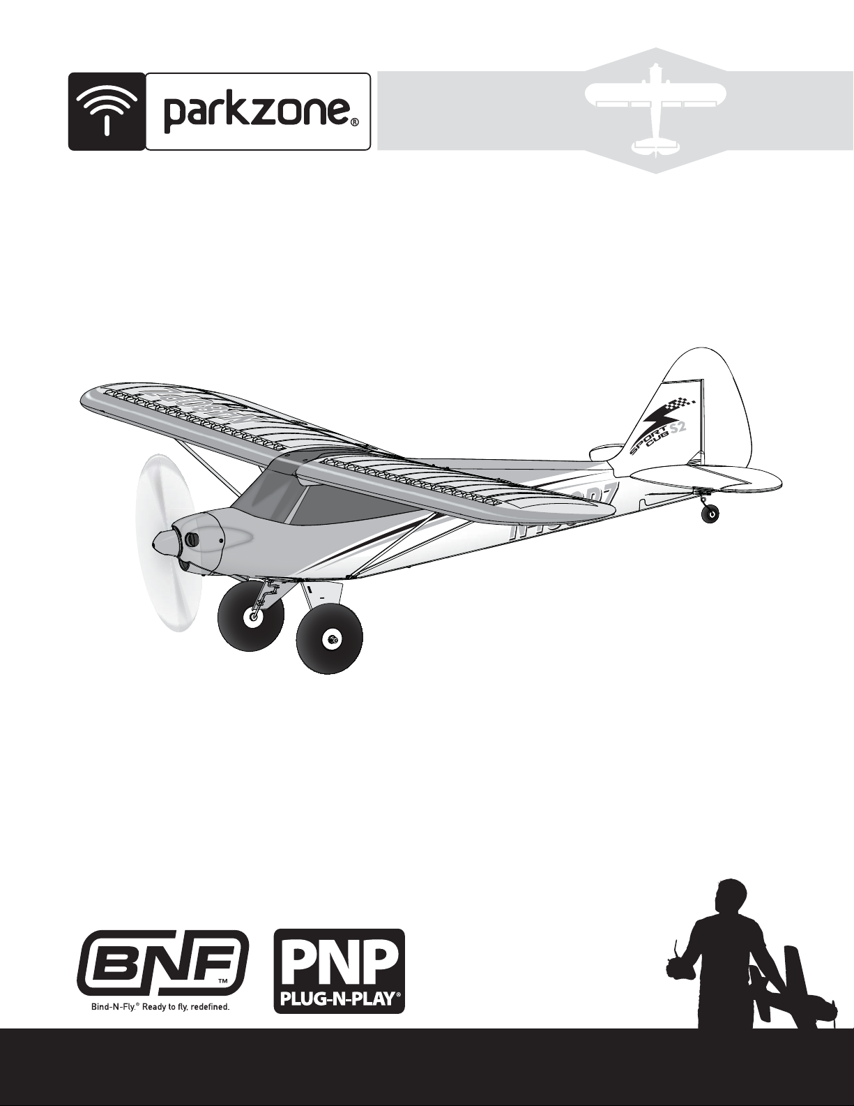
Sport Cub
Instruction Manual
Page 2
EN
NOTICE
All instructions, warranties and other collateral documents are subject to change at the sole discretion of Horizon Hobby, LLC. F
literature, visit www.horizonhobby.com and click on the support tab for this product.
Meaning of Special Language:
The following terms are used throughout the product literature to indicate various levels of potential harm when operating this product:
NOTICE: Procedures, which if not properly followed, create a possibility of physical property damage AND little or no possibility of injury.
CAUTION: Procedures, which if not properly followed, create the probability of physical property damage AND a possibility of serious injury.
WARNING: Procedures, which if not properly followed, create the probability of property damage, collateral damage, and serious injury OR create a high
probability of superfi cial injury.
WARNING: Read the ENTIRE instruction manual to become familiar with the features of the product before operating. Failure to operate the product
correctly can result in damage to the product, personal property and cause serious injury.
This is a sophisticated hobby product. It must be operated with caution and common sense and requires some basic mechanical ability. Failure to operate this Product in a safe and responsible manner could result in injury or damage to the product or other property. This product is not intended for use by
children without direct adult supervision. Do not use with incompatible components or alter this product in any way outside of the instructions provided by
Horizon Hobby, LLC. This manual contains instructions for safety, operation and maintenance. It is essential to read and follow all the instructions and warnings in the manual, prior to assembly, setup or use, in order to operate correctly and avoid damage or serious injury.
WARNING AGAINST COUNTERFEIT PRODUCTS: If you ever need to replace your Spektrum product found in a Horizon Hobby product, always purchase
from Horizon Hobby, LLC. or a Horizon Hobby authorized dealer to ensure authentic high-quality Spektrum product. Horizon Hobby, LLC. disclaims all
support and warranty with regards, but not limited to, compatibility and performance of counterfeit products or products claiming compatibility with DSM
or Spektrum.
or up-to-date product
Age Recommendation: Not for children under 14 years. This is not a toy.
Safety Precautions and Warnings
As the user of this product, you are solely responsible for operating in a manner
that does not endanger yourself and others or result in damage to the product
or the property of others.
• Always keep a safe distance in all directions around your model to avoid
collisions or injury. This model is controlled by a radio signal subject to
interference from many sources outside your control. Interference can cause
momentary loss of control.
• Always operate your model in open spaces away from full-size vehicles,
traffi c and people.
• Always carefully follow the directions and warnings for this and any optional
support equipment (chargers, rechargeable battery packs, etc.).
• Always keep all chemicals, small parts and anything electrical out of the
reach of children.
• Always avoid water exposure to all equipment not specifi cally designed and
protected for this purpose. Moisture causes damage to electronics.
• Never place any portion of the model in your mouth as it could cause serious
injury or even death.
• Never operate your model with low transmitter batteries.
• Always keep aircraft in sight and under control.
• Always use fully charged batteries.
• Always keep transmitter powered on while aircraft is powered.
• Always remove batteries before disassembly.
• Always keep moving parts clean.
• Always keep parts dry.
• Always let parts cool after use before touching.
• Always remove batteries after use.
• Always ensure failsafe is properly set before fl ying.
• Never operate aircraft with damaged wiring.
• Never touch moving parts.
Battery Warning
The Battery Charger included with your aircraft is designed to safely balance and charge the Li-Po battery.
CAUTION: All instructions and warnings must be followed exactly. Mishandling of Li-Po batteries can result in a fi re, personal injury, and/or property damage.
• By handling, charging or using the included Li-Po battery, you assume all
risks associated with lithium batteries.
• If at any time the battery begins to balloon or swell, discontinue use immediately. If charging or discharging, discontinue and disconnect. Continuing
to use, charge or discharge a battery that is ballooning or swelling can result
in fi re.
• Always store the battery at room temperature in a dry area for best results.
• Always transport or temporarily store the battery in a temperature range of
40–120º F (5–49º C). Do not store the battery or aircraft in a car or direct
sunlight. If stored in a hot car, the battery can be damaged or even
catch fi re.
• Always charge batteries away from fl ammable materials.
• Always inspect the battery before charging and never charge
damaged batteries.
• Always disconnect the battery after charging, and let the charger cool
between charges.
2
• Always constantly monitor the temperature of the battery pack
while charging.
• ONLY USE A CHARGER SPECIFICALLY DESIGNED TO CHARGE LI-PO BATTERIES. Failure to charge the battery with a compatible charger may cause fi re
resulting in personal injury and/or property damage.
• Never discharge Li-Po cells to below 3V under load.
• Never cover warning labels with hook and loop strips.
• Never leave charging batteries unattended.
• Never charge batteries outside recommended levels.
• Never attempt to dismantle or alter the charger.
• Never allow minors to charge battery packs.
• Never charge batteries in extremely hot or cold places (recommended
between 40–120° F or 5–49° C) or place in direct sunlight.
Page 3
EN
Table of Contents
Box Contents ..................................................................................................3
Specifi cations ................................................................................................. 3
Transmitter and Receiver Binding .................................................................... 4
Battery Charging ............................................................................................. 4
Battery Installation and ESC Arming ................................................................ 5
Receiver Selection and Installation .................................................................. 5
Landing Gear Installation ................................................................................ 6
Tail Installation ................................................................................................ 6
Clevis Installation ............................................................................................ 6
Wing Assemby and Installation ........................................................................ 7
Control Horn and Servo Arm Settings .............................................................. 8
Flap Installation .............................................................................................. 8
Dual Rates ...................................................................................................... 9
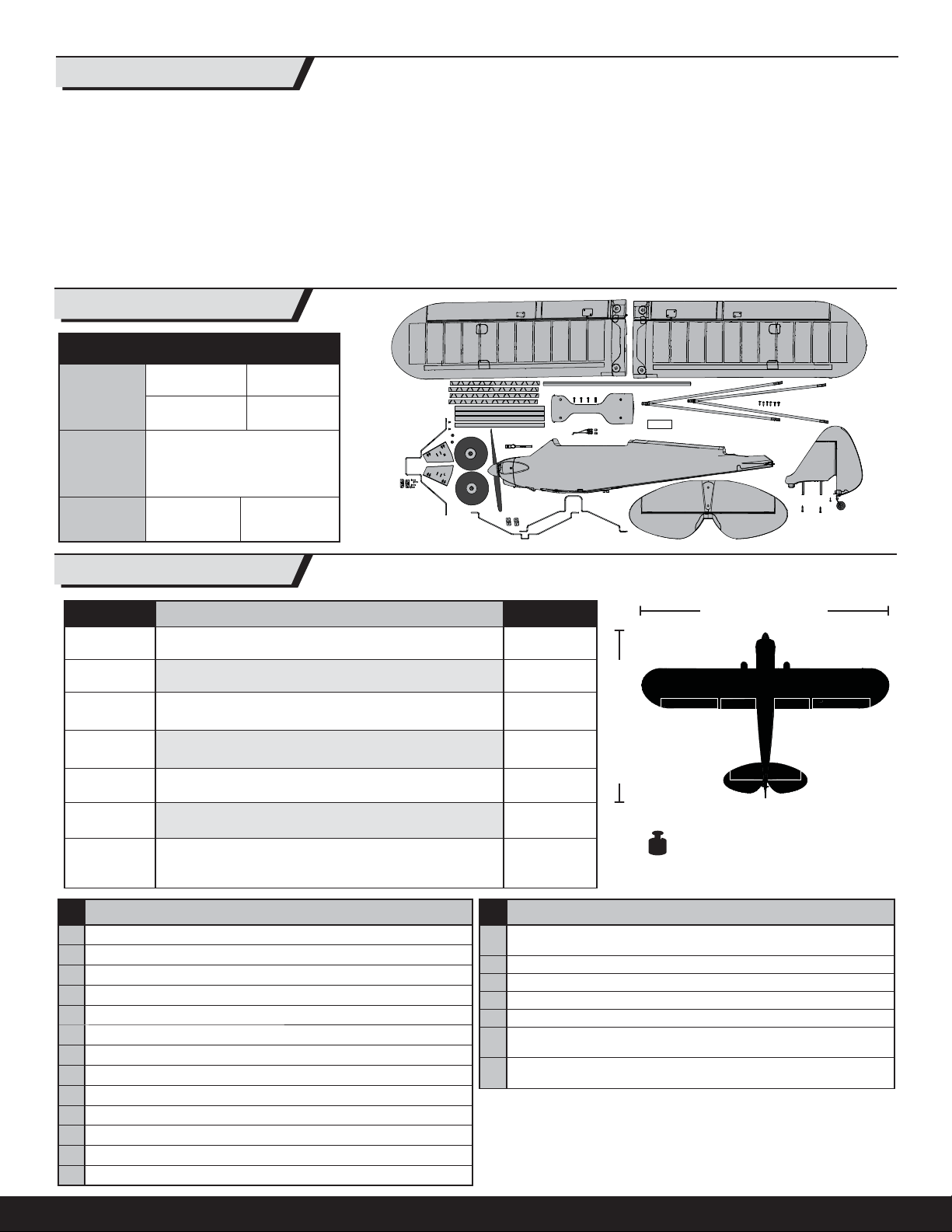
Box Contents
Quick Start Reference
High Low
Dual Rates
100 % 70%
63-66mm
CG
Flight Timer
Setting
2.50 - 2.60 inches back from the
leading edge of the wing at the
First Flight
5 Min.
root.
7 Min.
Transmitter Setup ........................................................................................... 9
Center of Gravity (CG) ................................................................................... 10
Control Direction Test .................................................................................... 10
AS3X Control Direction Test ........................................................................... 11
Flying Tips .................................................................................................... 12
Flaps. ........................................................................................................... 12
Motor Service ...............................................................................................13
Troubleshooting Guide AS3X .........................................................................13
Troubleshooting Guide .................................................................................. 14
Limited Warranty .......................................................................................... 15
Warranty and Service Contact Information .................................................... 15
Compliance Information for the European Union ............................................ 16
Replacement Parts ........................................................................................ 61
Optional Parts ............................................................................................... 62
Specifi cations
PNP BNF
Installed
Installed
Installed
Sold Separately
Sold Separately
Sold Separately
Sold Separately
9
1. Read this instruction manual thoroughly.
2. Remove and inspect the contents.
3. Charge the fl ight battery.
4. Fully assemble the model.
5. Install the fl ight battery in the aircraft (once it has been fully charged).
6. Bind the aircraft to your transmitter.
7. Make sure the linkages move freely.
8. Perform the Control Direction Test with the transmitter.
9. Perform the AS3X Control Direction Test with the aircraft.
10. Adjust the fl ight controls and transmitter.
11. Perform a radio system Range Check.
12. Find a safe and open area.
13. Plan fl ight for fl ying fi eld conditions.
480 Brushless Outrunner Motor, 960Kv (PKZ4416)
2 Aileron Servos, 1 Elevator Servo and
1 Rudder Servo (PKZ1081, PKZ1080, PKZ1090)
18-Amp Brushless ESC (PKZ1814)
Recommended Receiver
Spektrum AR636 6-Channel Sport Receiver (SPMAR636)
Recommended Battery
11.1V 3S 1300mAh 20C Li-Po (EFLB13003S20)
Recommended Battery Charger
3S Li-Po DC Balance Charger (HBZ1003)
Recommended Transmitter
Full-Range 4-Channel (or more) 2.4GHz with
Spektrum
Prefl ight Checklist
Motor
ESC
™
DSM2®/DSMX® technology
1300mm (51.0 in)
Installed
Installed
Installed
Installed
Included
Included
Sold Separately
9
1. Disconnect the fl ight battery from the ESC (Required for Safety
and battery life).
2. Power OFF the transmitter.
3. Remove the fl ight battery from the aircraft.
4. Recharge the fl ight battery.
5. Repair or replace all damaged parts.
6. Store the fl ight battery apart from the aircraft and monitor the
battery charge.
7. Make note of the fl ight conditions and fl ight plan results, planning for
future fl ight.
865mm (34.0 inches)
Weight:
945 grams (33.3 ounces) with battery
Post Flight Checklist
To register your product online, visit www.parkzone.com
3
Page 4
EN
Battery Charging
Refer to the charging warnings. It is recommended to charge the battery while
you inspect the aircraft. The fl ight battery will be required to confi rm proper
aircraft operation in future steps.
This Charger may be connected to a 1.5A AC Power Supply (US Only,
HBZ1004), sold separately.
DC Li-Po Balancing Charger (HBZ1003) Features
• Charges 3-cell lithium polymer
battery packs
• LED charge status indicator
• 12V accessory outlet connector
Specifi cations
• Input power: 10.5–14V DC, 3-amp
• Max output voltage: 11:1V
• Fixed charge current: 1.3A
• Charges 3-cell Li-Po packs with minimum
capacity of 1300mAh
Battery Charging Process
9
NOTICE: Charge only batteries that are cool to the touch and are not
damaged. Look at the battery to make sure it is not damaged e.g.,
swollen, bent, broken or punctured.
1. Attach the charger to the appropriate power supply (12V accessory
outlet).
2. Connect the Balancing Lead of the battery to the charger connector.
3. Charge the included battery for approximately 1 hr (the LED fl ashes
during charging, then turns solid when charging is complete).
4. Always disconnect the battery from the charger immediately upon
completion of charging.
CAUTION: Overcharging a battery can cause a fi re.
CAUTION: Only use a charger specifi cally designed to charge a Li-Po
battery. Failure to do so could result in fi re causing injury or property damage.
CAUTION: Never exceed the recommended charge rate.
NOTICE: If using a battery other than the included Li-Po battery, refer to your
battery manufacturer’s instructions for charging.
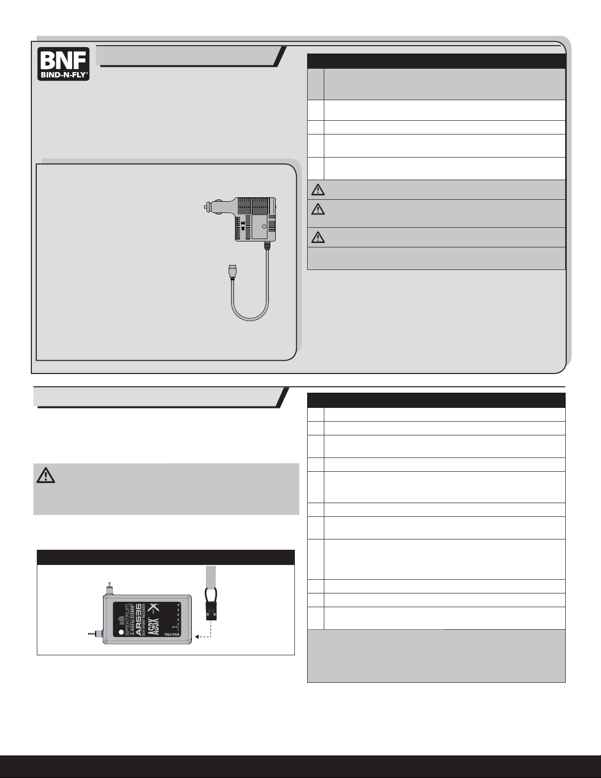
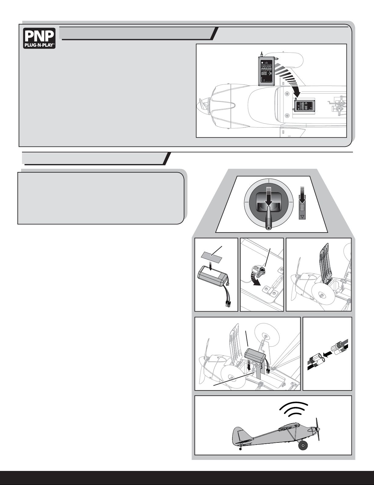
Transmitter and Receiver Binding
IMPORTANT: The AR636 receiver installed in the Bind-N-Fly aircraft has been
pre-programmed for operation in this aircraft. Refer to the receiver manual for
correct setup if the receiver is replaced or is used in another aircraft.
For a list of compatible DSM2/DSMX transmitters, please visit
www.bindnfl y.com.
CAUTION: When using a Futaba® transmitter with a Spektrum DSM®
module, you must reverse the throttle channel and rebind. Refer to your
Spektrum module manual for binding and failsafe instructions. Refer to your
Futaba transmitter manual for instructions on reversing the throttle channel.
Tip: A servo extension (PKZ5403, sold separately) may be installed in the
receiver bind port so binding may be done through the battery door in the
bottom of the aircraft.
Bind Plug Installation
Failsafe
If the receiver loses transmitter communication, the failsafe will activate. When
activated, the airplane controls return to the neutral position established during
step 3 of the binding procedure.
Binding Procedure Reference Table
9
1. Refer to your transmitter instructions for binding to a receiver.
2. Ensure the transmitter is powered off.
3. Make sure the transmitter controls are at neutral, and the throttle is
in the low position and the aircraft is immobile. *
4. Install a bind plug in the receiver bind port.
5. Connect the fl ight battery to the ESC. The ESC will produce a series
of sounds. One long tone, then three short tones confi rm that the
LVC is set for the ESC.
6. The receiver LED will begin to fl ash rapidly.
7. Power on the transmitter while holding the transmitter bind button
or switch.
8. When the receiver binds to the transmitter, the light on the receiver
will turn solid and the ESC will produce a series of three ascending
tones. The tones indicate the ESC is armed, provided the throttle
stick and throttle trim are low enough to trigger arming.
9. Remove the bind plug from the bind port.
10. Safely store the bind plug.
11. The receiver should retain the binding instructions received from
the transmitter until another binding is done.
* The throttle will not arm if the transmitter’s throttle control is not put at the
lowest position. If you encounter problems, follow the binding instructions
and refer to the transmitter troubleshooting guide for other instructions. If
needed, contact the appropriate Horizon Product Support offi ce.
4
Page 5
Receiver Selection and Installation
EN
The Spektrum AR636 receiver is recommended for this airplane. For an AR636
receiver purchased separately, download the setup for the ParkZone
Cub from www.spektrumrc.com and load it in the receiver, before installing
the receiver in the aircraft. If you choose to install another receiver, ensure
that it is at least a 4-channel full range (sport) receiver, or 5 or more channels
with fl aps. Refer to your receiver manual for correct installation and operation
instructions.
1. Before installing the wing, install a receiver in the fuselage.
2. Install your full range (sport) receiver in the fuselage using double-sided
servo tape.
3. Attach the elevator and rudder servo connectors to the appropriate
channels of the receiver.
4. Attach the aileron Y-harness to the aileron channel of the receiver.
5. Attach the ESC connector to the throttle channel of the receiver.
®
Sport
Battery Installation and ESC Arming
Battery Selection
• We recommend the E-fl ite® 1300mAh 11.1V 3S 20C Li-Po (EFLB13003S20).
• If using another battery, the battery must be at least a 1300mAh battery.
• Your battery should be approximately the same capacity, dimensions and
weight as the E-fl ite Li-Po battery to fi t in the fuselage without changing the
center of gravity a large amount.
1. Lower the throttle and throttle trim to the lowest settings. Power on the
transmitter, then wait 5 seconds.
2. Apply a strip of hook tape (A) to the bottom the battery near the end op-
posite the battery wires.
3. Turn the latch (B) and open the battery hatch.
4. Install the fully charged battery (C) even with the front edge of the support
covered with loop tape (as shown). See the Adjusting the Center of Gravity
instructions for more information.
5. Make sure the fl ight battery is secured using the hook and loop strap (D).
6. Connect the battery to the ESC. Keep the aircraft immobile and away from
wind for 5 seconds.
IMPORTANT: Due to the battery hatch location, it is easiest to install the battery and have the receiver initialize with the plane inverted.
• The ESC will sound a series of tones (refer to step 5 of the binding
instructions for more information).
• An LED will light on the receiver.
If the ESC sounds a continuous double beep after the fl ight battery is connected, recharge or replace the battery.
BA
C
D
7. Replace the battery hatch and turn the latch.
5
Page 6
EN
Landing Gear Installation
1. Install 2 tires (A) on the strut (B) using 2 wheel collars (C) and 2 set screws
(D). Tighten the set screws on the fl at spots of the strut.
Tip: Threadlock may be required to keep the collar on the strut.
2. If desired for scale appearance, install the left and right fairings (E) (marked
L and R) on the respective sides of the strut.
3. Turn the latch (F) and open the battery hatch.
4. Install the strut in the channels (G) in the fuselage as shown.
5. Install the left and right strut brackets (H) (marked L and R) in the respective slots on the bottom of the fuselage using 4 screws (I).
6. Replace the battery hatch and turn the latch.
Disassemble in reverse order.
Tail Installation
1. Install the horizontal tail (A) on the fuselage as shown.
2. Carefully insert the 2 pins of the vertical fi n (B) through the horizontal tail
holes and the fuselage holes. Turn the rudder so the control horn is under
the horizontal tail.
D
C
B
A
H
E
I
2.5 X 10mm (4)
Bag A
F
G
B
3. Under the fuselage, install the 2 screws (C) into the fuselage and the vertical fi n pins. Tighten the screws, but do not break the plastic.
4. Install the rudder hinge screw (D) as shown. Tighten the screw, then loosen
it one half of a turn so the rudder turns freely.
5. Connect the respective clevises in the outermost holes in the rudder and
elevator control horns. Refer to the clevis adjustment instructions to center
the rudder and elevators.
When needed, disassemble in reverse order.
Clevis Installation
Tip: Turn the clevis on the linkage to change the length of the linkage
between the servo arm and the control horn.
• Pull the tube from the clevis to the linkage.
• Carefully spread the clevis, then insert the clevis pin into the desired
hole in the control horn.
• Move the tube to hold the clevis on the control horn.
After binding a transmitter to the aircraft receiver, set the trims and
sub-trims to 0, then adjust the clevises to center the control surfaces.
1.
4.
A
C
3 X 14mm (2)
Bag B
2.
5.
I
3.
6.
2 X 8mm
Bag B
D
6
Page 7

Wing Assemby and Installation
Assembly
1. Install the vortex generators (A) in the wing channels (B) by using doublesided tape (C).
EN
CAUTION: DO NOT crush or otherwise damage the wiring when
attaching the wing to the fuselage.
2. Slide the wing tube (D) in the hole in the left wing.
3. Slide the other end of the wing tube into the hole in the right wing until
both wings meet.
4. Install the wing cover (E) on the top of the wing, aligning the 4 holes as
shown.
We recommend installing the Flaps (optional) in
the wing before installing the wing on the fuselage.
See the following page for detailed instructions.
Installation
1. Connect the aileron servos from the wings to the Y-harness connectors in
the fuselage. The left and right aileron servos can be connected to either
side of the Y-harness.
A
C
B
E
F
D
3 X 12mm (4)
Bag C
IMPORTANT: Correct operation of the AS3X system requires connection of
both ailerons to the included Y-harness and the AILE channel of the receiver.
Tip: A servo extension (PKZ5403, sold separately) may be installed in the receiver bind port so binding may be done through the battery door in the bottom
of the aircraft.
2. Attach the assembled wing and wing cover (E) to the fuselage using 4
screws (F).
3. Attach the left (G) and right (H) struts (marked L and R) under the wing and
fuselage using 6 screws (I).
IMPORTANT: On the wings, tighten the 4 screws in the middle of the strut slots
so the wings are not pulled down (Fig J).
Disassemble in reverse order.
Fig. J
I
2.5 X 10mm (6)
Bag C
G H
7
Page 8

EN
OPTIONAL
IMPORTANT: If desired, install the optional fl aps before installing the wing.
1. Install a tube on each clevis (Fig. A).
2. Connect the fl ap servo (PKZ1090, sold separately) to a servo extension
(PKZ5403, sold separately).
3. Connect the servo extension to the AUX1 port of the receiver.
4. Power on the transmitter and move the fl ap or gear switch to the up position.
5. Install the servo arm on the servo at the angle shown (Fig. B).
6. Install the fl ap linkage in the outermost hole of the fl ap servo arm (Fig.B).
7. Install the fl ap servo (A) in the pocket (B) using hot glue or
double-sided tape.
8. Attach the clevises to the fl ap torque rods as shown (Fig. C).
9. On both fl aps, carefully cut a small amount of foam at the fl ap hinge (C)
and wing root (D) so the fl aps move freely (see illustration).
10. Do a control test of the fl aps using your aircraft and transmitter. Make sure
both fl aps are symmetrical while they are retracted and extended.
Flap Installation
1/2 or Takeoff Full
Flap Down 12mm down 25mm down
A
Fig. A
B
Fig. B
Fig. C
D
C
Control Horn and Servo Arm Settings
The table to the right shows the factory settings for the control horns and servo
arms. Fly the aircraft at factory settings before making changes.
NOTICE: If control throws are changed from the reccomended
settings, the AR636 gain values will need to be adjusted. Refer to
the Spektrum AR636 manual for adjustment of gain values.
After fl ying, you may choose to adjust the linkage positions for the
desired control response. See the table below.
More control throw Less control throw
Factory Settings
Horns Arms
Elevator
Rudder
Ailerons
8
Page 9

Transmitter Setup
EN
IMPORTANT: The AR636 receiver installed in the Bind-N-Fly aircraft has been
pre-programmed for operation in this aircraft. Refer to the receiver manual for
correct setup if the receiver is replaced or is used in another aircraft.
A DSM2/DSMX four-channel (or better) transmitter with dual rates is required
for fl ying this aircraft. The Spektrum
DX10t, DX18 and JR
The settings below are recommended starting settings.
For the best fl ight experience, we recommend fl ying your aircraft with the
Dual Rate switched to high rate. However, if the control response is too
great, low rate is still available.
®
X9503, 11X or 12X transmitters may be used.
™
DX4e, DX5e, DX6i, DX7s, DX8, DX9,
Transmitters DX6i and Above
Servo travel ......................................................................................100%
Always leave servo travel at 100%. Use dual rates for a low rate setting. For
proper fl ight performance, do not set dual rates below 50% (only possible on
a computerized transmitter).
Tip: DX6i transmitters can activate all three channel rates (aileron, elevator
and rudder) using a combined Dual Rates switch. Rates and expo can also
be adjusted if the recommended rates are not comfortable.
Tip: DX7s and above transmitters can activate rates on one Dual Rates
switch like the DX6i transmitter. However, DX7s and above transmitters can
also activate rates and exponential on the same switch as the fl ight mode
(Channel 5).
Dual Rates
Dual Rate High Rate Low Rate
Aileron 100% 70%
Elevator 100% 70%
Rudder 100% 70%
Transmitters DX4e and DX5e
9
Before binding for Non-computerized Transmitters (DX4e, DX5e):
1. Set all trims to NEUTRAL (0%).
2. Move the transmitter Dual Rate switch to High Rate.
After binding:
1. Check and adjust the servos so each arm’s neutral position is
perpendicular or as close to 90° as possible (loosen and adjust the
servo arm splines on the servo only when needed). DO NOT use
sub-trims to make fi ne adjustments, off-center sub-trim will affect
servo travel and AS3X operation.
2. Adjust linkage lengths so the control surfaces center when the
servo arm is close to perpendicular.
3. Set rates in the transmitter as recommended.
NOTICE: If using a non-computer radio, reduce fl ap throw to half or the
aircraft may pitch up unexpectedly.
CAUTION: For safe operation, always re-bind the airplane after setup
is complete to ensure the failsafe is updated with the latest setup.
Transmitter Setup Checklist
9
Before binding for Computerized Transmitters (DX6i, DX7/DX7se, DX7s,
DX8, DX9, DX10t, DX18):
1. Choose a blank model memory with only default (zero) settings
(including trim and sub-trim).
2. Choose Wing/Aircraft Type for single aileron servo.
3. Set all sub-trims to NEUTRAL (0%).
4. Set servo travel values to 100% for Aileron, Elevator, and Rudder.
5. Set the Dual Rate to 100%, 70% for Aileron, Elevator, and Rudder.
After binding:
1. Check and adjust the servos so each arm’s neutral position is
perpendicular or as close to 90° as possible (loosen and adjust the
servo arm splines on the servo only when needed). DO NOT use
sub-trims to make fi ne adjustments, off-center sub-trim will affect
servo travel and AS3X operation.
2. Adjust linkage lengths so the control surfaces center when the
servo arm is close to perpendicular.
3. Set rates in the transmitter as recommended.
CAUTION: For safe operation, always re-bind the airplane after setup
is complete to ensure the failsafe is updated with the latest setup.
9
Page 10

EN
Center of Gravity (CG)
The CG location is 63 - 66mm back from the leading edge of the wing at the
root. Make sure the fl ight battery is secured using the hook and loop strap.
Aircraft CG and weight is based on an E-fl ite 11.1V 1300mAh 30C battery
(EFLB13003S20) installed.
Control Direction Test
63 - 66mm
2.50 - 2.60 inches
back from the
leading edge of the
wing at the root.
Move the controls on the transmitter to make sure the aircraft control
surfaces move in the proper direction.
Transmitter
Command
Up Elevator
Command
Down
Elevator
Elevator
Command
Stick Right
Aileron
Stick Left
Aircraft Reaction
10
Stick Right
Rudder
Stick Left
Page 11

AS3X Control Direction Test
EN
Perform the Control Direction Test to ensure the aircraft responds correctly to your transmitter. Once you are sure the aircraft responds correctly, move the aircraft as shown to ensure the AS3X system moves
the control surfaces in their proper direction. If the control surfaces
do not respond as shown, do not fl y the aircraft. Refer to the receiver
manual for more information.
The AS3X system will not activate until the throttle stick or trim is
increased for the fi rst time after the fl ight battery is connected. Once
the AS3X is active, the control surfaces may move rapidly on the
aircraft. This is normal. AS3X will remain active until the battery is
disconnected.
Aircraft
movement
ElevatorAileronRudder
AS3X Reaction
11
Page 12

EN
Flying Tips
Consult local laws and ordinances before choosing a fl ying location.
Range Check your Radio System
After fi nal assembly, range check the radio system with the aircraft. Refer to
your specifi c transmitter instruction manual.
Takeoff
Place the aircraft in position for takeoff (facing into the wind). Select low rates
for fi rst takeoff and gradually increase the throttle to 3/4 to full and steer with
the rudder. Pull back gently on the elevator and climb to a comfortable altitude.
Wind
Fly in this area
600
feet (182.8 m)
Stand here
Flying
Fly the airplane and trim it for level fl ight at 3/4 throttle. After landing, adjust
the linkages mechanically to account for trim changes and then reset the trims
to neutral. Ensure the aircraft will fl y straight and level with no trim or sub-trim.
NOTICE: If a crash is imminent, reduce the throttle
and trim fully. Failure to do so could result in extra
damage to the airframe, as well as damage to the
ESC and motor.
NOTICE: Crash damage is not covered under warranty.
NOTICE: When you are fi nished fl ying, never leave the
aircraft in direct sunlight or in a hot, enclosed area
such as a car. Doing so can damage the foam.
Always
decrease throttle at
propeller strike.
Low Voltage Cutoff (LVC)
When a Li-Po battery is discharged below 3V per cell, it will not hold a charge.
The ESC protects the fl ight battery from over-discharge using Low Voltage
Cutoff (LVC). Before the battery charge decreases too much, LVC removes
power supplied to the motor. Power to the motor pulses, showing that some
battery power is reserved for fl ight control and safe landing.
Disconnect and remove the Li-Po battery from the aircraft after use to prevent
trickle discharge. Charge your Li-Po battery to about half capacity before storage. During storage, make sure the battery charge does not fall below 3V
per cell. LVC does not prevent the battery from over-discharge during storage.
NOTICE: Repeated fl ying to LVC will damage the battery.
Tip: Monitor your aircraft battery’s voltage before and after fl ying by using a
Li-Po Cell Voltage Checker (EFLA111, sold separately).
Flaps
When using flaps, takeoffs and landings are shorter. When taking off, the tail
will come off the ground quicker for better rudder control during the takeoff
roll.
During landing, the fl aps allow a landing approach to be steeper because of
the increased drag. Flaps make the plane come in at a slower airspeed and
make it easier to flare and settle in for a smooth landing. When deploying the
flaps, slow the aircraft down to 1/4 throttle. If the flaps are deployed when the
aircraft is at a higher speed, the aircraft will pitch up. Set your down elevator
to flap mixing at 30% to reduce the pitch up tendency.
NOTICE: If using a non-computer radio, reduce fl ap throw to half or the aircraft
may pitch up unexpectedly when fl aps are deployed.
Landing
Flight times of 7 minutes or more are achievable if using proper throttle
management.
For your fi rst fl ights, set your transmitter timer or a stopwatch to 5 minutes.
Adjust your timer for longer or shorter fl ights once you have fl own the model.
If the motor pulses, land the aircraft immediately and recharge the fl ight battery. It is not recommended to fl y the battery to Low Voltage Cutoff (LVC).
To land the aircraft, fl y the aircraft down to the ground using 1/4 –1/3
throttle to allow for enough energy for a proper fl are. The aircraft is easiest to
land doing a wheel landing (two point), where the aircraft touches down on the
main landing gear fi rst while the tailwheel is still off the ground. The aircraft
can also be landed in a three-point attitude, where all three wheels touch
down at the same time. When the aircraft touches down, reduce back pressure
on the elevator stick to prevent the plane from becoming airborne again.
Repairs
Thanks to the Z-Foam™ construction of this aircraft, repairs to the foam can
be made using virtually any adhesive (hot glue, regular CA, epoxy, etc). When
parts are not repairable, see the Replacement Parts List for ordering by item
number. For a listing of all replacement and optional parts, refer to the list at
the end of this manual.
NOTICE: Use of CA accelerant on your aircraft can damage paint. DO NOT
handle the aircraft until accelerant fully dries.
Optional Floats
To fl y this aircraft off water, install the optional HobbyZone® Float Set
(HBZ7390, sold separately). Float struts, strut brackets and 4 screws are
included with the aircraft. Rear bracket screws are included with the fl oats.
Refer to the fl oat manual for installation and water operation instructions.
If landing on grass, it is best to hold full up elevator after touchdown and when
taxiing to prevent nosing over.
Once on the ground, avoid sharp turns until the plane has slowed enough to
prevent scraping the wingtips.
12
Page 13

Motor Service
EN
Disassembly
CAUTION: Always disconnect the fl ight battery from the aircraft before
removing the propeller.
1. Remove the screw (A) and spinner (B) from the collet (C).
2. Remove the spinner nut (D), propeller (E), spinner backplate (F), backplate
(G) and collet from the motor shaft (H). You will need a tool to turn the spinner nut.
3. Remove the 3 screws (I) from the cowling (J). Carefully remove the cowling
from the fuselage. Paint may keep the cowling attached to the fuselage.
4. Remove the 4 screws (K) from the motor mount (L) and the fuselage.
5. Disconnect the motor wires from the ESC wires.
6. Remove the 4 screws (M) and motor (N) from the motor mount.
Not all wiring shown.
DC N
EJ
G
I
Assembly
Assemble in reverse order.
• Correctly align and connect the motor wire colors with the ESC wires.
• The propeller size numbers (9 x 6) must face out from the motor for correct
propeller operation.
• A tool is required to tighten the spinner nut on the collet.
• Ensure the spinner is fully connected to the spinner backplate for safe
operation.
AB F L MH
Troubleshooting Guide AS3X
Problem Possible Cause Solution
Trim change
when fl
ight
mode is switched
Incorrect
response to the
AS3X Control
Direction Test
Trim is not at neutral If you need to adjust the trim more than 8 clicks, return the trim to neutral and manually adjust the clevis
Sub-Trim is not at neutral Do not use Sub-Trim. Adjust the servo arm or the clevis
Incorrect direction settings in
the receiver, which can cause
a crash
to center the trim
DO NOT fl y. Correct the direction settings (refer to the receiver manual), then fl y
K
13
Page 14

EN
Troubleshooting Guide
Problem Possible Cause Solution
Aircraft will not respond to throttle but
responds to other
controls
Extra propeller noise
or extra vibration
Reduced fl ight time
or aircraft underpowered
Aircraft will not Bind
(during binding) to
transmitter
Aircraft will not connect (after binding) to
transmitter
Control surface does
not move
Controls reversed Transmitter settings are reversed Perform the Control Direction Test and adjust the controls on
Motor power pulses
then motor loses
power
Aircraft control
surfaces do not
move after battery is
connected
Throttle not at lowest position or throttle trim too high Reset controls with throttle stick and throttle trim at lowest setting
Throttle servo travel is lower than 100% Make sure throttle servo travel is 100% or greater
Throttle channel is reversed Reverse throttle channel on transmitter
Motor disconnected from ESC Make sure motor is connected to the ESC
Damaged propeller and spinner, collet or motor Replace damaged parts
Propeller is out of balance Balance or replace propeller
Prop nut is too loose Tighten the prop nut
Spinner is not tight or fully seated in place Tighten the spinner or remove the spinner and turn it 180 degrees
Flight battery charge is low Completely recharge fl ight battery
Propeller installed backwards Install propeller with numbers facing forward
Flight battery damaged Replace fl ight battery and follow fl ight battery instructions
Flight conditions may be too cold Make sure battery is warm before use
Battery C rating is too low Replace battery or use battery with correct C rating
Transmitter too near aircraft during binding process Move powered transmitter a few feet from aircraft, disconnect and recon-
Aircraft or transmitter is too close to large metal object,
wireless source or another transmitter
The bind plug is not installed correctly in the bind port Install bind plug in bind port and bind the aircraft to the transmitter
Flight battery/Transmitter battery charge is too low Replace/recharge batteries
Bind switch or button not held long enough during bind
process
Transmitter too near aircraft during connecting process Move powered transmitter a few feet from aircraft, disconnect and
Aircraft or transmitter is too close to large metal object,
wireless source or another transmitter
Bind plug left installed in bind port Rebind transmitter to the aircraft and remove the bind plug before
Aircraft bound to different model memory (ModelMatch
radios only)
Flight battery/Transmitter battery charge is too low Replace/recharge batteries
Transmitter may have been bound using different DSM
protocol
Control surface, control horn, linkage or servo damage Replace or repair damaged parts and adjust controls
Wire damaged or connections loose Do a check of wires and connections, connect or replace as needed
Transmitter is not bound correctly or the incorrect model
was selected
Flight battery charge is low Fully recharge fl ight battery
BEC (Battery Elimination Circuit) of the ESC is damaged Replace ESC
ESC uses default soft Low Voltage Cutoff (LVC) Recharge fl ight battery or replace battery that is no longer performing
Weather conditions might be too cold Postpone flight until weather is warmer
Battery is old, worn out, or damaged Replace battery
Battery C rating might be too small Use recommended battery
Aircraft was moving during initialization Keep aircraft still during initialization
nect fl ight battery to aircraft
Move aircraft and transmitter to another location and attempt
binding again
Power off transmitter and repeat bind process. Hold transmitter bind
button or switch until receiver is bound
reconnect fl ight battery to aircraft
Move aircraft and transmitter to another location and attempt
connecting again
cycling power
TM
Select correct model memory on transmitter
Bind aircraft to transmitter
Re-bind or select correct model in transmitter
transmitter appropriately
14
Page 15

Limited Warranty
EN
What this Warranty Covers
Horizon Hobby, LLC. (“Horizon”) warrants to the original purchaser that the
product purchased (the “Product”) will be free from defects in materials and
workmanship at the date of purchase.
What is Not Covered
This warranty is not transferable and does not cover (i) cosmetic damage, (ii)
damage due to acts of God, accident, misuse, abuse, negligence, commercial
use, or due to improper use, installation, operation or maintenance, (iii) modification of or to any part of the Product, (iv) attempted service by anyone other
than a Horizon Hobby authorized service center, (v) Product not purchased
from an authorized Horizon dealer, or (vi) Product not compliant with applicable technical regulations.
OTHER THAN THE EXPRESS WARRANTY ABOVE, HORIZON MAKES NO OTHER
WARRANTY OR REPRESENTATION, AND HEREBY DISCLAIMS ANY AND ALL
IMPLIED WARRANTIES, INCLUDING, WITHOUT LIMITATION, THE IMPLIED
WARRANTIES OF NON-INFRINGEMENT, MERCHANTABILITY AND FITNESS
FOR A PARTICULAR PURPOSE. THE PURCHASER ACKNOWLEDGES THAT THEY
ALONE HAVE DETERMINED THAT THE PRODUCT WILL SUITABLY MEET THE
REQUIREMENTS OF THE PURCHASER’S INTENDED USE.
Purchaser’s Remedy
Horizon’s sole obligation and purchaser’s sole and exclusive remedy shall be
that Horizon will, at its option, either (i) service, or (ii) replace, any Product
determined by Horizon to be defective. Horizon reserves the right to inspect
any and all Product(s) involved in a warranty claim. Service or replacement
decisions are at the sole discretion of Horizon. Proof of purchase is required
for all warranty claims. SERVICE OR REPLACEMENT AS PROVIDED UNDER
THIS WARRANTY IS THE PURCHASER’S SOLE AND EXCLUSIVE REMEDY.
Limitation of Liability
HORIZON SHALL NOT BE LIABLE FOR SPECIAL, INDIRECT, INCIDENTAL
OR CONSEQUENTIAL DAMAGES, LOSS OF PROFITS OR PRODUCTION OR
COMMERCIAL LOSS IN ANY WAY, REGARDLESS OF WHETHER SUCH CLAIM IS
BASED IN CONTRACT, WARRANTY, TORT, NEGLIGENCE, STRICT LIABILITY OR
ANY OTHER THEORY OF LIABILITY, EVEN IF HORIZON HAS BEEN ADVISED OF
THE POSSIBILITY OF SUCH DAMAGES. Further, in no event shall the liability of
Horizon exceed the individual price of the Product on which liability is asserted. As Horizon has no control over use, setup, final assembly, modification or
misuse, no liability shall be assumed nor accepted for any resulting damage
or injury. By the act of use, setup or assembly, the user accepts all resulting
liability. If you as the purchaser or user are not prepared to accept the liability
associated with the use of the Product, purchaser is advised to return the
Product immediately in new and unused condition to the place of purchase.
Law
These terms are governed by Illinois law (without regard to conflict of law
principals). This warranty gives you specific legal rights, and you may also
have other rights which vary from state to state. Horizon reserves the right to
change or modify this warranty at any time without notice.
WARRANTY SERVICES
Questions, Assistance, and Services
Your local hobby store and/or place of purchase cannot provide warranty support or service. Once assembly, setup or use of the Product has been started,
you must contact your local distributor or Horizon directly. This will enable
Horizon to better answer your questions and service you in the event that
you may need any assistance. For questions or assistance, please visit our
website at www.horizonhobby.com, submit a Product Support Inquiry, or call
the toll free telephone number referenced in the Warranty and Service Contact
Information section to speak with a Product Support representative.
Inspection or Services
If this Product needs to be inspected or serviced and is compliant in the
country you live and use the Product in, please use the Horizon Online Service
Request submission process found on our website or call Horizon to obtain a
Return Merchandise Authorization (RMA) number. Pack the Product securely
using a shipping carton. Please note that original boxes may be included,
but are not designed to withstand the rigors of shipping without additional
protection. Ship via a carrier that provides tracking and insurance for lost or
damaged parcels, as Horizon is not responsible for merchandise until it arrives
and is accepted at our facility. An Online Service Request is available at http://
www.horizonhobby.com/content/_service-center_render-service-center. If you
do not have internet access, please contact Horizon Product Support to obtain
a RMA number along with instructions for submitting your product for service.
When calling Horizon, you will be asked to provide your complete name, street
address, email address and phone number where you can be reached during
business hours. When sending product into Horizon, please include your RMA
number, a list of the included items, and a brief summary of the problem. A
copy of your original sales receipt must be included for warranty consideration. Be sure your name, address, and RMA number are clearly written on the
outside of the shipping carton.
NOTICE: Do not ship LiPo batteries to Horizon. If you have any issue with
a LiPo battery, please contact the appropriate Horizon Product Support
office.
Warranty Requirements
For Warranty consideration, you must include your original sales receipt
verifying the proof-of-purchase date. Provided warranty conditions have
been met, your Product will be serviced or replaced free of charge. Service or
replacement decisions are at the sole discretion of Horizon.
Non-Warranty Service
Should your service not be covered by warranty, service will be completed and payment will be required without notification or estimate
of the expense unless the expense exceeds 50% of the retail purchase
cost. By submitting the item for service you are agreeing to payment of the
service without notification. Service estimates are available upon request. You
must include this request with your item submitted for service. Non-warranty
service estimates will be billed a minimum of ½ hour of labor. In addition you
will be billed for return freight. Horizon accepts money orders and cashier’s
checks, as well as Visa, MasterCard, American Express, and Discover cards.
By submitting any item to Horizon for service, you are agreeing to Horizon’s
Terms and Conditions found on our website http://www.horizonhobby.com/
content/_service-center_render-service-center.
ATTENTION: Horizon service is limited to Product compliant in the country of use and ownership. If received, a non-compliant Product will not
be serviced. Further, the sender will be responsible for arranging return
shipment of the un-serviced Product, through a carrier of the sender’s
choice and at the sender’s expense. Horizon will hold non-compliant
Product for a period of 60 days from notification, after which it will be
discarded.
Warranty and Service Contact Information
Country of Purchase Horizon Hobby Address Phone Number/Email Address
Horizon Service Center
United States of America
United Kingdom Horizon Hobby Limited
Germany Horizon Technischer Service
France Horizon Hobby SAS
China Horizon Hobby – China
(Air)
Horizon Product Support
(All other products)
4105 Fieldstone Rd
Champaign, Illinois 61822 USA
4105 Fieldstone Rd
Champaign, Illinois 61822 USA
Units 1-4 Ployters Rd
Staple Tye Harlow, Essex
CM18 7NS, United Kingdom
Christian-Junge-Straße 1
25337 Elmshorn, Germany
11 Rue Georges Charpak
77127 Lieusaint, France
Room 506, No. 97 Changshou Rd.
Shanghai, China, 200060
888-959-2305
Online Repair Request:
visit www.horizonhobby.com/service
877-504-0233
productsupport@horizonhobby.com
+44 (0) 1279 641 097
sales@horizonhobby.co.uk
+49 (0) 4121 2655 100
service@horizonhobby.de
+33 (0) 1 60 18 34 90
infofrance@horizonhobby.com
+86 (021) 5180 9868
info@horizonhobby.com.cn
15
Page 16

EN
Compliance Information for the European Union
Declaration of Conformity
(in accordance with ISO/IEC 17050-1)
No. HH2014041002
Product(s): Sport Cub BNF
Item Number(s): PKZ6880
Equipment class: 1
The object of declaration described above is in conformity with the requirements of the specifi cations listed below, following the provisions of the
European R&TTE directive 1999/5/EC, EMC Directive 2004/108/EC and LVD
Directive 2006/95/EC:
EN 301 489-1 V1.9.2: 2012
EN 301 489-17 V2.1.1: 2009
EN60950-1:2006+A11:2009+A1:2010+A12: 2011
EN55022:2010 + AC:2011
EN55024:2010
Signed for and on behalf of:
Horizon Hobby, LLC
Champaign, IL USA
Apr 10, 2014
Chief Financial Offi cer
Robert Peak
Horizon Hobby, LLC
Declaration of Conformity
(in accordance with ISO/IEC 17050-1)
No. HH2014041001
Product(s): Sport Cub PNP
Item Number(s): PKZ6875
Equipment class: 1
The object of declaration described above is in conformity with the requirements of the specifi cations listed below, following the provisions of the EMC
Directive 2004/108/EC:
EN55022:2010 + AC:2011
EN55024:2010
Signed for and on behalf of:
Horizon Hobby, LLC
Champaign, IL USA
Apr 10, 2014
Chief Financial Offi cer
Robert Peak
Horizon Hobby, LLC
Instructions for disposal of WEEE by users in the European Union
This product must not be disposed of with other waste. Instead, it is the user’s responsibility to dispose of their waste equipment by handing it over
to a designated collections point for the recycling of waste electrical and electronic equipment. The separate collection and recycling of your waste
equipment at the time of disposal will help to conserve natural resources and ensure that it is recycled in a manner that protects human health and
household waste disposal service or where you purchased the product.
the environment. For more information about where you can drop off your waste equipment for recycling, please contact your local city offi ce, your
16
Page 17

Replacement Parts • Ersatzteile • Pièces de rechange • Pezzi di ricambio
Part # | Nummer
Numéro | Codice
PKZ6802
PKZ6806
PKZ6804
PKZ6807
PKZ6805
PKZ6867
PKZ6808
PKZ6809
PKZ6820
PKZ6621
PKZ6821
PKZ6822
PKZ6801
PKZ4416
PKZ6803
PKZ1814
SPMAR636
EFLB13003S20
PKZ1019
PKZ1080
PKZ1081
PKZ1090
HBZ1003
Description Beschreibung Description Descrizione
Spinner: Sport Cub Spinner: Sport Cub Cône: Sport Cub Ogiva: Sport Cub
Landing gear set: Sport Cub Fahrwerk-Set: Sport Cub Jeu de train d'atterrissage principal : Sport Cub Set del carrello di atterraggio: Sport Cub
Tail Set: Sport Cub Leitwerk: Sport Cub Empennages : Sport Cub Set coda: Sport Cub
Decal Sheet: Sport Cub Dekorbogen: Sport Cub Planche de décoration : Sport Cub Foglio adesivi: Sport Cub
Pushrod Set: Sport Cub Gestänge Set: Sport Cub Set de tringleries : Sport Cub Set rinvii: Sport Cub
Fuselage: Sport Cub Parkzone Sport Cub: Rumpf Fuselage : Sport Cub Fusoliera: Sport Cub
Motor mount: Sport Cub Motorbefestigung: Sport Cub Support moteur: Sport Cub Supporto del motore: Sport Cub
Battery Door: Sport Cub Akkuklappe: Sport Cub Trappe à batterie : Sport Cub Portello batteria: Sport Cub
Main Wing: Sport Cub Tragfl äche: Sport Cub Aile : Sport Cub Ala principale: Sport Cub
Wing Tube: Sport Cub Tragfl ächenstreben: Sport Cub Clé d’aile : Sport Cub Baionetta ala: Sport Cub
Wing Struts: Sport Cub Flächenverbinder: Sport Cub Haubans : Sport Cub Montanti ala: Sport Cub
Vortex Generators: Sport Cub Vortex Generatoren: Sport Cub Générateurs de vortex : Sport Cub Turbolatori: Sport Cub
Cowl: Sport Cub Motorhaube: Sport Cub Capot : Sport Cub Capottina motore: Sport Cub
480 Brushless Outrunner Motor 960Kv Parkzone Bl Außenläufer 960kV Moteur brushless 480 à cage tournante 960Kv Motore 480 brushless a cassa rotante
Prop Adapter: Sport Cub Propeller Adapter: Sport Cub Adaptateur d’hélice : Sport Cub Adattatore elica: Sport Cub
18-Amp Brushless ESC Parkzone 18A Regler Contrôleur brushless 18A Regolatore (ESC) brushless 18A
Spektrum 6-Channel AS3X Sport
Receiver
1300mAh 3S 20C 11.1v LiPo 1300 mAh 3S 20C 11,1 V LiPo Accu LiPo 1300mAh 3S 20C 11,1V 1300 mAh 3S 20C 11,1 V LiPo
Propeller: 9 x 6 Propeller: 9 x 6 Hélice 9 x 6 Elica: 9 x 6
SV80 Short Lead Servo Parkzone SV80 Servo Servo de Dérive SV80 SV80 Servo con cavo lungo corto
SV80 Long Lead Servo
DSV130 digital servo, metal gear Parkzone DSV130 Digitalservo MG Servo DSV130 digital, pignons métal
3S Li-Po DC Balance Charger Hobbyzone 3S Lipo Balance Lader Chargeur équilibreur Li-Po 3S
Spektrum 6 Kanal AS3X Sport
Empfänger
Parkzone SV80 Servo mit langem
Kabel
Récepteur Spektrum 6 voies avec AS3X Ricevitore sport AS3X Spektrum 6 canali
Servo SV80 à câble long Servo SV80 a cavo lungo
Servo digitale DSV130, ingranaggi
metallo
Caricatore DC con bilanciamento per
LiPo 3S
61
Page 18

Optional Parts • Optionale Bauteile • Pièces optionnelles • Pezzi opzionali
Part # | Nummer
Numéro | Codice
EFLA250
EFLAEC302
EFLAEC303
PKZ1033
PKZ1031
EFLB18003S30
EFLB13003S20
EFLB22003S30
PKZ1029
EFLA111
DYNC2010
HBZ7390
PKZ1090
PKZ5403
HBZ1004
HBZ1004EU
HBZ1004UK
DYN1405
DYN1400
Description Beschreibung Description Descrizione
Park Flyer Tool Assortment, 5 pc
EC3 Battery Connector (2) E-fl ite EC3 Akkukabel, Buchse (2) Prises EC3 coté batterie (2) Connettore batteria
EC3 Device/Battery Connector E-fl ite EC3 Kabelsatz, Stecker/Buchse Prises EC3 coté contrôleur (2) Connettore batteria/dispositivo
1300mAh 11.1V Li-Po Battery with
EC3 Connector
11.1V 1800mAh 3S LiPo Battery
1800mAh 3S 11.1V 30C
LiPo,13AWG EC3
1300mAh 3S 11.1V 20C
LiPo,13AWG EC3
2200mAh 3S 11.1V 30C
LiPo,13AWG EC3
11.1V 3S 25C 2200MAH Li-Po 11.1V 3S 25C 2200mAh LiPo 11.1V 3S 25C 2200MAH Li-Po 11.1V 3S 25C 2200MAH Li-Po
Li-Po Cell Voltage Checker E-fl ite Li-Po Cell Volt Checker Contrôleur de tension Li-Po Controllo tensione batteria LiPo
Prophet Sport Plus 50W AC DC
Charger
Float Set: Super Cub LP
DSV130 digital servo, metal gear Parkzone DSV130 Digitalservo MG Servo DSV130 digital, pignons métal
Servo Extension Querruderservoverlängerung Rallonge de servo Prolunga per servo
1.5A AC Power Supply
(US Only)
1.5A AC Power Supply
(EU Only)
1.5A AC Power Supply
(UK Only)
Li-Po Charge Protection Bag, Large
Li-Po Charge Protection Bag, Small
DX4e DSMX 4-Channel Transmitter
DX5e DSMX 5-Channel Transmitter
DX6i DSMX 6-Channel Transmitter Spektrum DX6i DSMX 6-Kanal Sender Emetteur DX6i DSMX 6 voies DX6i DSMX Trasmettitore 6 canali
DX7s DSMX 7-Channel Transmitter Spektrum DX7s DSMX 7 Kanal Sender Emetteur DX7s DSMX 7 voies DX7s DSMX Trasmettitore 7 canali
DX8 DSMX 8-Channel Transmitter Spektrum DX8 DSMX 8 Kanal Sender Emetteur DX8 DSMX 8 voies DX8 DSMX Trasmettitore 8 canali
DX9 DSMX 9-Channel Transmitter Spektrum DX9 DSMX 9 Kanal Sender Emetteur DX9 DSMX 9 voies DX9 DSMX Trasmettitore 9 canali
DX18 DSMX 18-Channel Transmitter
E-fl ite Park Flyer Werkzeugsortiment;
5 teilig
1300mAh 11.1V Li-Po Akku
mit EC3 Anschluss
11.1V 1800mAh 3S LiPo
Akku
1800mAh 3S 11.1V 30C
LiPo,13AWG EC3
1300mAh 3S 11.1V 20C
LiPo,13AWG EC3
2200mAh 3S 11.1V 30C
LiPo,13AWG EC3
Dynamite Ladegerät Prophet Sport
Plus 50W AC/DC EU
Hobbyzone Schwimmersatz für Super
Cub LP
1.5A AC Power Supply (US Only)
1.5A AC Power Supply (EU Only)
1.5A AC Power Supply (UK Only)
Dynamite LiPoCharge Protection Bag
groß
Dynamite LiPoCharge Protection Bag
klein
Spektrum DX4e DSMX 4 Kanal Sender
ohne Empfänger
Spektrum DX5e DSMX 5 Kanal Sender
ohne Empfänger
Spektrum DX18 DSMX 18 Kanal
Sender
Assortiment d'outils park fl yer, 5pc Park Flyer assortimento attrezzi, 5 pc
Batterie Li-Po 3S 11.1V 1300mA avec
prise EC3
Batterie Li-Po 3S 11.1V 1800mA avec
prise EC3
Batterie Li-Po 3S 11.1V 1800mA 30C
avec prise EC3
Batterie Li-Po 3S 11.1V 1300mA 20C
avec prise EC3
Batterie Li-Po 3S 11.1V 2200mA 25C
avec prise EC3
Chargeur Prophet Sport Plus 50W AC DC
Set de fl otteurs : Super Cub LP Set galleggianti: Super Cub LP
Alimentation secteur 1.5A
(USA uniquement)
Alimentation secteur 1.5A
(EU uniquement)
Alimentation secteur 1.5A
(UK uniquement)
Sac de charge Li-Po, grand modèle Busta protezione grande par LiPo
Sac de charge Li-Po, petit modèle Busta protezione piccola par LiPo
Emetteur DX4e DSMX 4 voies DX4e DSMX Trasmettitore 4 canali
Emetteur DX5e DSMX 5 voies DX5e DSMX Trasmettitore 5 canali
Emetteur DX18 DSMX 18 voies DX18 DSMX Trasmettitore 18 canali
Batteria LiPo 1300mAh 11,1V con
connettore EC3
Batteria LiPo 1800mAh 11,1V
Batteria LiPo 1800mAh 11,1V 30C
con connettore EC3 13AWG
Batteria LiPo 1300mAh 11,1V 20C
con connettore EC3 13AWG
Batteria LiPo 2200mAh 11,1V 30C
con connettore EC3 13AWG
Caricatore Prophet Sport Plus 50W
AC D
Servo digitale DSV130, ingranaggi
metallo
1.5A AC Alimentatore (solo USA)
1.5A AC Alimentatore (solo EU)
1.5A AC Alimentatore (solo UK)
62
Page 19

© 2014 Horizon Hobby, LLC
ParkZone, E-flite, HobbyZone, Prophet, EC3, DSM, DSM2, DSMX, Z-Foam, Bind-N-Fly, the BNF logo, Plug-N-Play
and ModelMatch are trademarks or registered trademarks of Horizon Hobby, LLC.
The Spektrum trademark is used with permission of Bachmann Industries, Inc.
Futaba is a registered trademark of Futaba Denshi Kogyo Kabushiki Kaisha Corporation of Japan.
Cub Crafters, Sport Cub, associated emblems and logos, and body designs of vehicles are either registered trademarks
or trademarks of Cub Crafters, Inc. and are used with permission.
JR is a registered trademark of JR Americas.
All other trademarks, service marks and logos are property of their respective owners.
www.parkzone.com
PKZ6875, PKZ6880
Created 04/14 35799.1
 Loading...