

ParkZone PKZ7150 User Manual
Habu 2
Instruction Manual • Bedienungsanleitung • Manuel d’utilisation • Manuale di Istruzioni

EN EN
NOTICE
All instructions, warranties and other collateral documents are subject to change at the sole discretion of Horizon Hobby, Inc. For up-to-date product
literature, visit www.horizonhobby.com and click on the support tab for this product.
Meaning of Special Language:
The following terms are used throughout the product literature to indicate various levels of potential harm when operating this product:
NOTICE: Procedures, which if not properly followed, create a possibility of physical property damage AND little or no possibility of injury.
CAUTION: Procedures, which if not properly followed, create the probability of physical property damage AND a possibility of serious injury.
WARNING: Procedures, which if not properly followed, create the probability of property damage, collateral damage, and serious injury OR create a high
probability of superfi cial injury.
WARNING: Read the ENTIRE instruction manual to become familiar with the features of the product before operating. Failure to operate the product
correctly can result in damage to the product, personal property and cause serious injury.
This is a sophisticated hobby product. It must be operated with caution and common sense and requires some basic mechanical ability. Failure to operate this Product in a safe and responsible manner could result in injury or damage to the product or other property. This product is not intended for use
by children without direct adult supervision. Do not attempt disassembly, use with incompatible components or augment product in any way without the
approval of Horizon Hobby, Inc. This manual contains instructions for safety, operation and maintenance. It is essential to read and follow all the instructions
and warnings in the manual, prior to assembly, setup or use, in order to operate correctly and avoid damage or serious injury.
Age Recommendation: Not for children under 14 years. This is not a toy.
Safety Precautions and Warnings
As the user of this product, you are solely responsible for operating in a manner
that does not endanger yourself and others or result in damage to the product
or the property of others.
• Always keep a safe distance in all directions around your model to avoid
collisions or injury. This model is controlled by a radio signal subject to
interference from many sources outside your control. Interference can cause
momentary loss of control
• Always operate your model in open spaces away from full-size vehicles,
traffi c and people.
• Always carefully follow the directions and warnings for this and any optional
support equipment (chargers, rechargeable battery packs, etc.).
• Always keep all chemicals, small parts and anything electrical out of the
reach of children.
• Always avoid water exposure to all equipment not specifi cally designed and
protected for this purpose. Moisture causes damage to electronics.
• Never place any portion of the model in your mouth as it could cause serious
injury or even death.
• Never operate your model with low transmitter batteries.
• Always keep aircraft in sight and under control.
• Always use fully charged batteries.
• Always keep transmitter powered on while aircraft is powered.
• Always remove batteries before disassembly.
• Always keep moving parts clean.
• Always keep parts dry.
• Always let parts cool after use before touching.
• Always remove batteries after use.
• Always ensure failsafe is properly set before fl ying.
• Never operate aircraft with damaged wiring.
• Never touch moving parts.
2
– Introduction –
You are about to take fl ight with one of the hottest electric ducted fans ever built. Its potent one-two punch of speed and precision aerobatic ability will make
every fl ight one to remember. Before you take to the sky though, you must read through this manual. The ParkZone
and things happen fast. The better understanding you have of its performance and systems prior to your fi rst fl ight, the better that fl ight will be.
®
Habu 2 can cover a lot of ground in a hurry
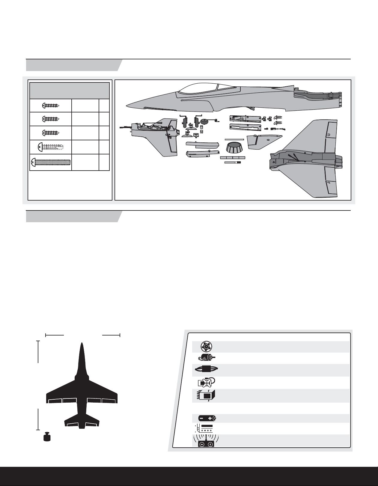
Box Contents
Included Screws and Fasteners
Size Qty
2X8mm 6
2.5X8mm 7
ENEN
2.5X8mm
(black)
3X10mm 4
3X25mm 3
Spare fasteners may be included.
4
Table of Contents
Low Voltage Cutoff (LVC) ................................................................... 4
Transmitter and Receiver Binding ...................................................... 4
Installing the Battery ......................................................................... 4
Arming the ESC Before Flight ............................................................ 5
Installing the Wing ............................................................................ 5
Installing Optional Flaps .................................................................... 6
Installing the E-fl ite Optional Retractable Landing Gear ..................... 7
Installing the E-fl ite Optional Retractable Landing Gear (Continued) ... 8
Installing the Fixed Landing Gear ...................................................... 9
Attaching the Tail ............................................................................ 10
Installing Clevises on Control Horns and Control Centering .............. 11
Factory Settings .............................................................................. 11
Center of Gravity (CG) ..................................................................... 11
Control Direction Test ...................................................................... 12
BIND PLUG
Dual Rates ...................................................................................... 13
Service of Power Components ........................................................ 13
Prefl ight Checklist ........................................................................... 14
Flying Tips and Repairs ................................................................... 14
Post Flight Checklist ....................................................................... 15
AMA National Model Aircraft Safety Code ........................................ 15
Troubleshooting Guide .................................................................... 16
Limited Warranty ............................................................................ 17
Contact Information ........................................................................ 18
Compliance Information for the European Union .............................. 18
Replacement Parts .......................................................................... 67
Optional Parts ................................................................................. 68
Parts Contact Information ............................................................... 68
36.3 in (920mm)
43.3 in (1100mm)
Weight: (RTF ) 51.8 oz (1470 g)*
Weight: (RTF with Flaps and Retracts) 54.7 oz (1550 g)*
* Weight is with E-Flite 3200mAh 4 cell Lipo (EFLB32004S30)
To register your product online, visit www.parkzone.com
Installed
Ducted Fan Unit: Delta-V® 15 69mm EDF Fan Unit (EFLDF15)
Motor: BL15 Ducted Fan Motor, 3200Kv (EFLM3215DF)
ESC: 60-Amp Pro Switch-Mode BEC Brushless ESC
(EFLA1060)
(5) Servos
™
Receiver: Spektrum
range sport receiver
AR600 2.4GHz DSM2®/DSMX® full
Needed to Complete
Battery: 3200mAh 14.8V 4-cell 30C Li-Po (EFLB32004S30)
Battery Charger: 3–4 cell Li-Po battery charger (PKZ7040)
Required Transmitter: Full-Range 2.4GHz with Spektrum
DSM2/DSMX technology.
™
3
EN
BIN
D
/DATA
THR
O
AILE
ELEV
RUDD
GEAR
AUX
1
2.4GHz DSM® TECHNOLOGY
6CH SPORT RECEIVER 2048
Low Voltage Cutoff (LVC)
When a Li-Po battery is discharged below 3V per cell, it will not hold a charge.
The ESC protects the fl ight battery from over-discharge using Low Voltage
Cutoff (LVC). Before the battery charge decreases too much, LVC removes
power supplied to the motor. Power to the motor pulses, showing that some
battery power is reserved for fl ight control and safe landing.
When the motor pulses, land the aircraft immediately and recharge the
fl ight battery.
Disconnect and remove the Li-Po battery from the aircraft after use to prevent
trickle discharge. Charge your Li-Po battery to about half capacity before storage. During storage, make sure battery charge does not fall below 3V per cell.
Transmitter and Receiver Binding
Binding is the process of programming the receiver of the control unit to recognize the GUID (Globally Unique Identifi er) code of a single specifi c transmitter. You
need to ‘bind’ your chosen Spektrum DSM2/DSMX technology equipped aircraft transmitter to the receiver for proper operation.
Please visit www.bindnfl y.com for a complete list of compatible transmitters.
NOTICE: When using a Futaba transmitter with a Spektrum DSM
throttle channel.
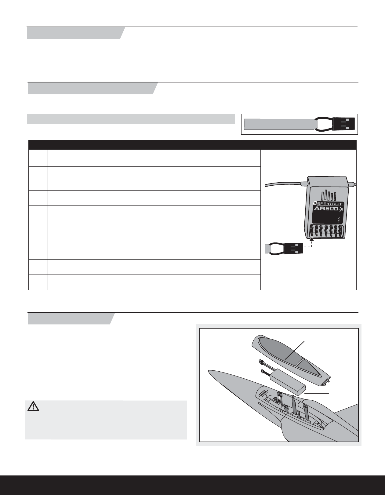
Binding Procedure Reference Table
1. Read the transmitter instructions for binding to a receiver (location of transmitter’s Bind control).
2. Make sure the transmitter is powered off.
3. Move the transmitter controls to neutral (fl ight controls: rudder, elevators and ailerons) or to low
positions (throttle, throttle trim).*
4. Install a bind plug in the receiver bind port.
5. Connect the fl ight battery to the ESC. The ESC will produce a series of sounds. One long tone,
then three short tones confi rm that the LVC is set for the ESC.
6. Power on the ESC switch. The receiver LED will begin to fl ash rapidly.
7. Power on the transmitter while holding the transmitter bind button or switch. Refer to your
transmitter’s manual for binding button or switch instructions.
8. When the receiver binds to the transmitter, the light on the receiver will turn solid and the ESC
will produce a series of four ascending tones. The tones will indicate the ESC is armed, provided
the throttle stick and throttle trim are low enough to trigger arming.
9. Remove the bind plug from the bind port.
10. Safely store the bind plug (some owners attach the bind plug to their transmitter using two-part
loops and clips).
11. The receiver should retain the binding instructions received from the transmitter until another
binding is done.
®
module, you must reverse the
BIND PLUG
* The throttle will not arm if the transmitter’s throttle control is not put at the lowest position. If you encounter problems, follow binding instructions and refer to
the transmitter troubleshooting guide for other instructions. If needed, contact the appropriate Horizon Product Support offi ce.
Installing the Battery
1. Carefully lift the front of the canopy (A) and pull the canopy forward and off
the fuselage.
2. Place the blue battery connector toward the front of the airplane and install
the fl ight battery (B) all the way to the front of the battery compartment.
3. If binding the aircraft receiver to the transmitter, refer to the transmitter
manual’s binding instructions. If the aircraft is already bound to the transmitter, always power on the transmitter before connecting the fl ight battery
to the ESC connector in the aircraft.
4. Install the canopy on the fuselage. Make sure the magnets on the canopy
and fuselage meet.
CAUTION: Always disconnect the Li-Po battery from the aircraft
receiver when not fl ying to avoid over-discharging the battery. Batteries
discharged to a voltage lower than the lowest approved voltage may become
damaged, resulting in loss of performance and potential fi re when batteries
are charged.
4
A
B
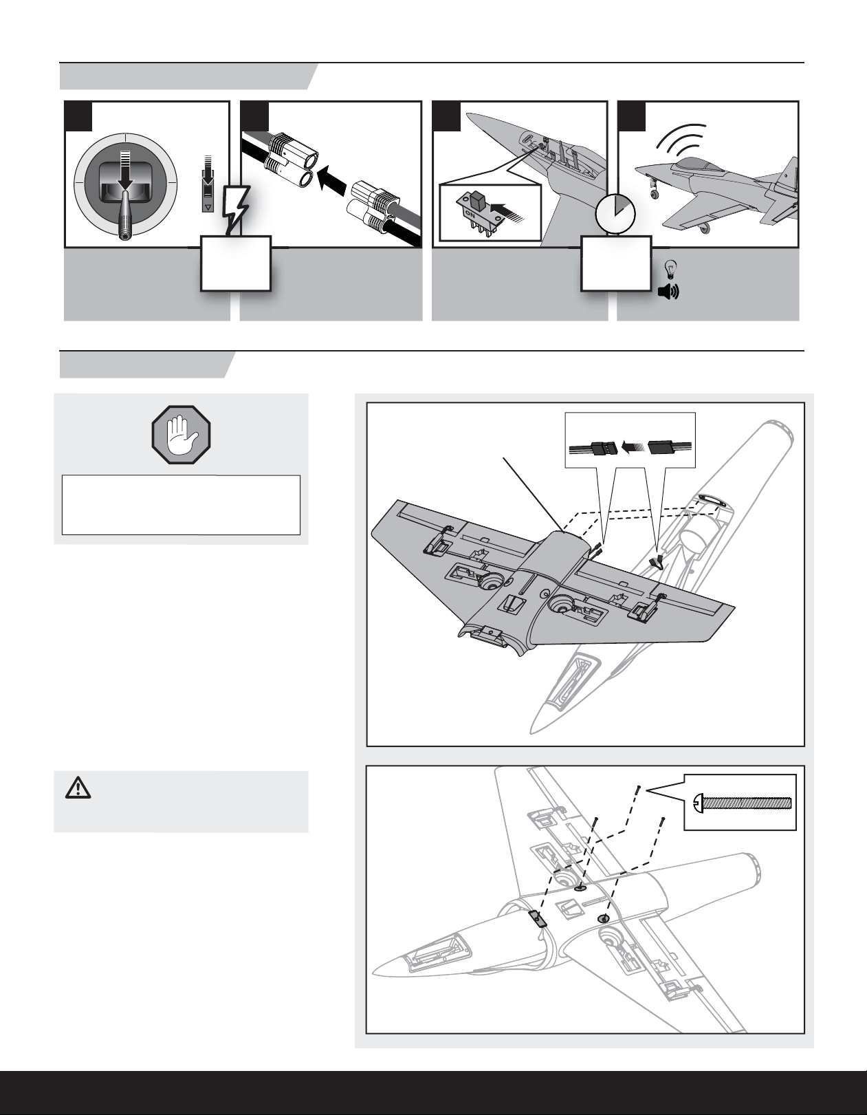
Arming the ESC Before Flight
1 3 42
EN
• Lower throttle and
throttle trim to
lowest settings.
Power on
Transmitter
Installing the Wing
If you plan on installing optional fl aps or retracts,
you must do so before installing the wing. Please
proceed to the following pages for instructions.
1. Remove the canopy from the fuselage.
2. Turn the wing and fuselage so their bottom
sides face up.
3. Slide the two guide pins (A) of the wing into the
two holes in the fuselage.
4. Connect both aileron servo connectors (B) to
the aileron Y-harness. The left and right servo
connectors do not have to be connected to a
particular side of the Y-harness.
5. Align and attach the wing to the fuselage using
3 screws (C). The 2 rear screws are longer than
the front screw.
6. When needed, disassemble in reverse order.
• Connect battery to ESC.
• Power on ESC switch.
A
Wait 5
seconds
Continuous LED
Series of tones
B
CAUTION: DO NOT crush or otherwise
damage wiring when attaching the wing to the
fuselage.
NOTICE: Use of CA (cyanocrylate adhesive) accelerant on your model can damage paint. DO NOT
handle the model until the accelerant fully dries.
C
3 X 25mm
5
EN
using only stock parts, proceed to the Installing the Landing Gear section.
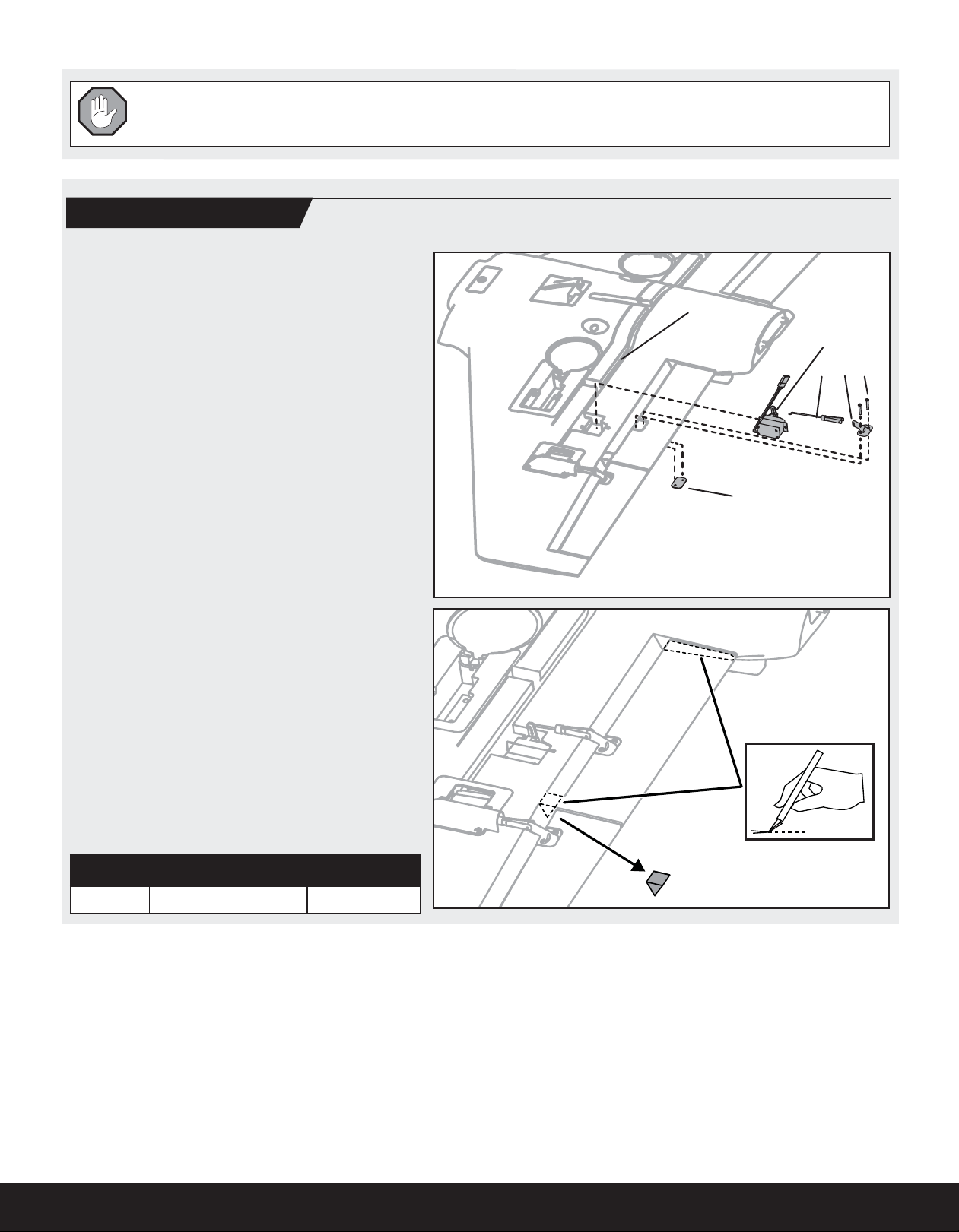
Installing Optional Flaps
1. Install the left and right fl ap servos (A)
(PKZ1081 x 2, sold separately) in the wing
pocket using hot glue or double-sided tape.
2. Install the control horns (B) and plates (C) on
the wing using 2 screws (D) in each horn.
3. Install a connector and clevis (E) in the second
innermost hole of the servo arm and outer hole
of the control horn.
4. Carefully cut a wedge of foam from the fl ap
hinge near the aileron hinge (see illustration).
5. Carefully cut a small amount of foam at the
fl ap and wing root so the fl ap moves freely
(see illustration).
6. Remove the tape to put the servo wires in the
wing channel (F).
7. Put the fl ap servo wires in the wing channel
with the aileron wires.
8. Install the fl ap servo connector in the hole at
the wing root.
9. Place tape over the channel.
10. Cut a small amount of tape at the fl ap servo to
let the servo arm move freely.
11. Adjust the clevis so the fl ap is not pulled fully
against the wing at the hinge when the fl ap is
operated.
12. Install the servo connectors in the fuselage.
13. Install the wing on the fuselage using installa-
tion instructions on the previous page.
If you are assembling your aircraft
F
A
E
B D
C
NOTICE: Make sure wires are not crushed or
damaged when the wing is attached to
the fuselage.
14. Attach the servo connectors to the correct
receiver channels or Y-harnesses.
15. Do a control test of the fl aps using your aircraft
and transmitter.
1/2 or Takeoff Flap Full Flaps
Flap down 13mm down 25mm down
6
 Loading...