

ParkZone PKZ6375 User Manual

DH 98 Mosquito Mk VI
Instruction Manual / Bedienungsanleitung
Manuel d’utilisation / Manuale di Istruzioni
EN
NOTICE
All instructions, warranties and other collateral documents are subject to change at the sole discretion of Horizon Hobby, Inc. For up-to-date product
literature, visit www.horizonhobby.com and click on the support tab for this product.
Meaning of Special Language:
The following terms are used throughout the product literature to indicate various levels of potential harm when operating this product:
NOTICE: Procedures, which if not properly followed, create a possibility of physical property damage AND little or no possibility of injury.
CAUTION: Procedures, which if not properly followed, create the probability of physical property damage AND a possibility of serious injury.
WARNING: Procedures, which if not properly followed, create the probability of property damage, collateral damage, and serious injury OR create a high
probability of superfi cial injury.
WARNING: Read the ENTIRE instruction manual to become familiar with the features of the product before operating. Failure to operate the product
correctly can result in damage to the product, personal property and cause serious injury.
This is a sophisticated hobby product. It must be operated with caution and common sense and requires some basic mechanical ability. Failure to
operate this Product in a safe and responsible manner could result in injury or damage to the product or other property. This product is not intended for use
by children without direct adult supervision. Do not use with incompatible components or alter this product in any way outside of the instructions provided
by Horizon Hobby, Inc. This manual contains instructions for safety, operation and maintenance. It is essential to read and follow all the instructions and
warnings in the manual, prior to assembly, setup or use, in order to operate correctly and avoid damage or serious injury.
WARNING AGAINST COUNTERFEIT PRODUCTS: If you ever need to replace your Spektrum receiver found in a Horizon Hobby product, always purchase from
Horizon Hobby, Inc. or a Horizon Hobby authorized dealer to ensure authentic high-quality Spektrum product. Horizon Hobby, Inc. disclaims all support and
warranty with regards, but not limited to, compatibility and performance of counterfeit products or products claiming compatibility with DSM or Spektrum.
Age Recommendation: Not for children under 14 years. This is not a toy.
Safety Precautions and Warnings
As the user of this product, you are solely responsible for operating in a manner
that does not endanger yourself and others or result in damage to the product
or the property of others.
• Always keep a safe distance in all directions around your model to avoid
collisions or injury. This model is controlled by a radio signal subject to
interference from many sources outside your control. Interference can cause
momentary loss of control
• Always operate your model in open spaces away from full-size vehicles,
traffi c and people.
• Always carefully follow the directions and warnings for this and any optional
support equipment (chargers, rechargeable battery packs, etc.).
• Always keep all chemicals, small parts and anything electrical out of the
reach of children.
• Always avoid water exposure to all equipment not specifi cally designed and
protected for this purpose. Moisture causes damage to electronics.
• Never place any portion of the model in your mouth as it could cause serious
injury or even death.
• Never operate your model with low transmitter batteries.
• Always keep aircraft in sight and under control.
• Always use fully charged batteries.
• Always keep transmitter powered on while aircraft is powered.
• Always remove batteries before disassembly.
• Always keep moving parts clean.
• Always keep parts dry.
• Always let parts cool after use before touching.
• Always remove batteries after use.
• Always ensure failsafe is properly set before fl ying.
• Never operate aircraft with damaged wiring.
• Never touch moving parts.
2
The DH 98 Mosquito MK VI
This outstanding replica of the Mosquito Mk VI has been engineered to fl y every bit as good as it looks. Its twin brushless motors deliver impressive speed and
climb performance that perfectly complement the smooth, balanced control response. If this is your fi rst twin motor park fl yer, you’ll fi nd the counter-rotating
propellers help make tracking during takeoff and landing rollout much easier too.
Before you launch, though, you must take a little time to read this manual. It contains important information about assembly, recommended dual rates, installation
of option parts and much more. There’s also a handy trouble shooting guide. It’s all here to make sure your fi rst fl ight, and every one after, is the best it can be.
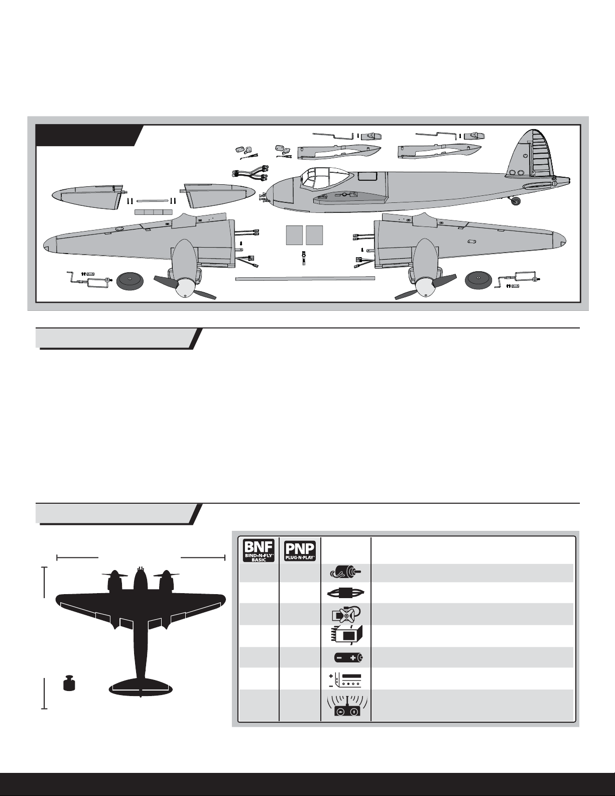
Box Contents
EN
Table of Contents
Transmitter and Receiver Binding .................................................................... 4
Receiver Selection and Installation .................................................................. 4
Battery Installation .......................................................................................... 5
ESC and Receiver Arming................................................................................ 5
E-fl ite Retractable Landing Gear ..................................................................... 6
Flap Installation .............................................................................................. 7
Wing Installation ............................................................................................. 8
Control Horn and Servo Arm Settings .............................................................. 8
Horizontal Tail Installation ............................................................................... 9
Clevis Installation ............................................................................................ 9
Fixed Landing Gear Installation .......................................................................9
Engine Scoop ................................................................................................ 10
First Flight Preparation .................................................................................. 10
Specifi cations
49.0 inches (1244mm)
Installed Installed
Installed Installed ESC: (2) 18A Brushless ESC (PKZ1814)
Installed Installed
Needed to
Complete
Needed to
Complete
Needed to
Complete
Needed to
Complete
37.6 inches (955mm)
Weight:
42.3 oz (1200 g)
44.4 oz (1260 g) with retracts and
fl ap servos installed
Installed
Needed to
Complete
Needed to
Complete
Needed to
Complete
Center of Gravity (CG) ................................................................................... 10
Control Direction Test .................................................................................... 11
Dual Rates .................................................................................................... 12
Flying Tips and Repairs ................................................................................. 12
Maintenance After Flying .............................................................................. 13
Service of Power Components ...................................................................... 13
Troubleshooting Guide .................................................................................. 14
Limited Warranty .......................................................................................... 15
Contact Information ......................................................................................16
Compliance Information for the European Union ............................................ 16
Replacement Parts ....................................................................................... 62
Optional Parts ............................................................................................... 63
Motor: (2) 370 Brushless Outrunner Motor, 1300Kv
(PKZ6116)
(2) Aileron Servos (PKZ1081)
(1) Rudder Servo (1) Elevator Servo (PKZ1090)
Receiver: Spektrum™ AR610 6-Channel DSMX Aircraft
Receiver
Battery: 11.1V 3S 2200mAh 25C Li-Po (PKZ1029)
Battery Charger: 300mA–2.0A 2- to 3-cell Li-Po battery
charger (PKZ1040)
Recommended Transmitter:
Full-Range 4-Channel (or more) 2.4GHz with Spektrum
®
/DSMX® technology.
DSM2
™
To register your product online, visit www.parkzone.com
3
EN
Transmitter and Receiver Binding
“Binding” is the process of programming the receiver to recognize the GUID
(Globally Unique Identifi er) code of a single specifi c transmitter. You need to
bind your chosen Spektrum
transmitter to the receiver for proper operation (please visit www.bindnfl y.com
for a complete list of compatible transmitters).
CAUTION: When using a Futaba® transmitter with a Spektrum DSM®
module, you must reverse the throttle channel and rebind. Refer to your
Spektrum module manual for binding and failsafe instructions. Refer to your
Futaba transmitter manual for instructions on reversing the throttle channel.
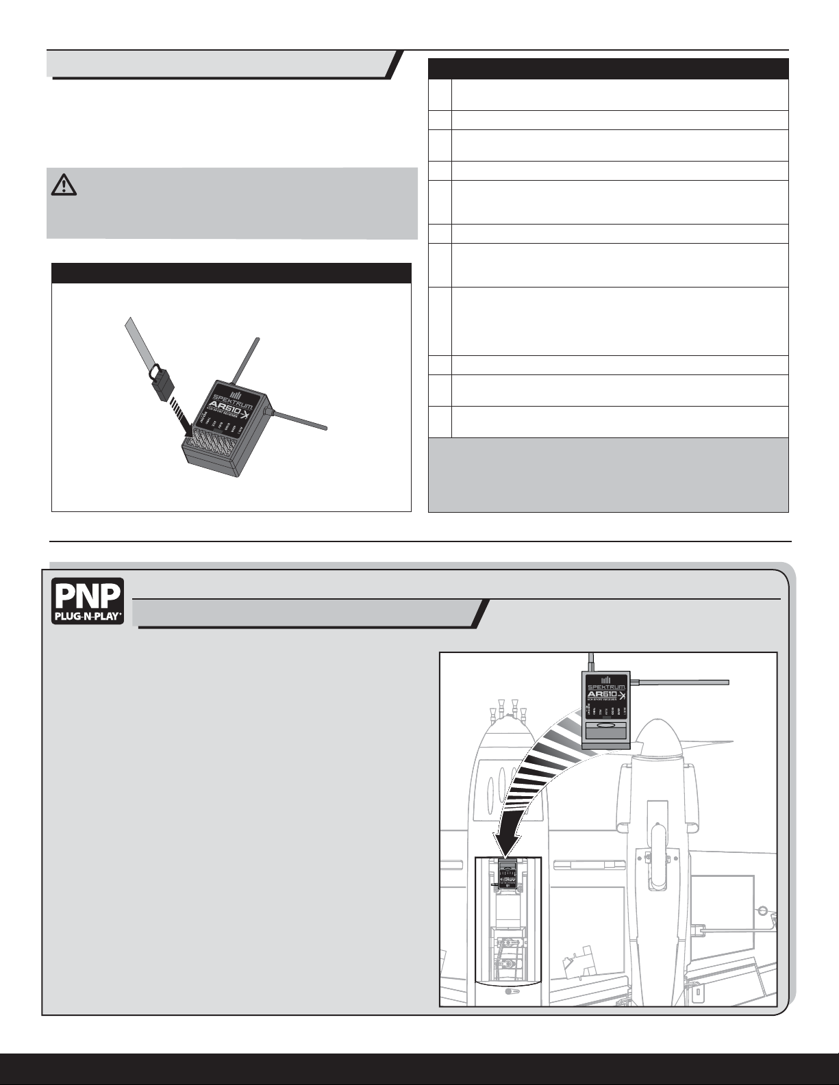
Bind Plug Installation
™
DSM2®/DSMX® technology equipped aircraft
Binding Procedure Reference Table
1. Read the transmitter instructions for binding to a receiver (location of transmitter’s Bind control).
2. Make sure the transmitter is powered OFF.
3. Move the transmitter controls to neutral (fl ight controls: rudder,
elevators and ailerons) or to low positions (throttle, throttle trim).*
4. Install a bind plug in the receiver bind port.
5. Connect the fl ight battery to the single connector of the ESC Yharness. The ESCs will produce a series of sounds. One long tone,
then two short tones confi rm that the LVC is set for the ESCs.
6. The receiver LED will begin to fl ash rapidly.
7. Power ON the transmitter while holding the transmitter bind
button or switch. Refer to your transmitter’s manual for binding
button or switch instructions.
8. When the receiver binds to the transmitter, the light on the
receiver will turn solid and the ESCs will produce a series of
three ascending tones. The tones indicate the ESCs are armed,
provided the throttle stick and throttle trim are low enough to
trigger arming.
9. Remove the bind plug from the bind port.
10. Safely store the bind plug (some owners attach the bind plug to
their transmitter using two-part loops and clips).
11. The receiver should retain the binding instructions received from
the transmitter until another binding is done.
* The throttle will not arm if the transmitter’s throttle control is not put at the
lowest position. If you encounter problems, follow the binding instructions
and refer to the transmitter troubleshooting guide for other instructions. If
needed, contact the appropriate Horizon Product Support offi ce.
Receiver Selection and Installation
A 4-channel or greater radio system is required for the PNP aircraft out of the
box. If optional fl aps and retracts are installed, a 6-channel or greater radio
system is required.
1. Install your park fl yer or full range receiver in the fuselage using hook and
loop tape or double-sided servo tape.
2. Attach the elevator and rudder servo connectors to the appropriate
channels of the receiver.
3. Attach the aileron Y-harness to the aileron channel of the receiver.
4. Attach the ESC connector to the throttle channel of the receiver.
4
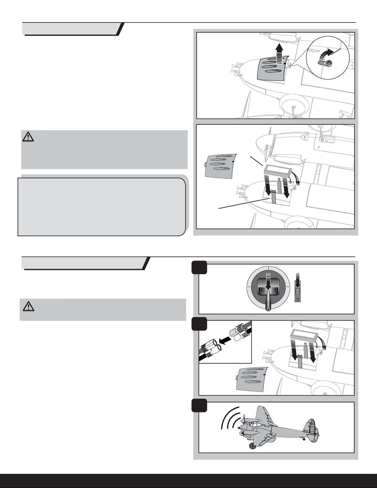
Battery Installation
1. Turn the latch (A).
2. Lift the back of the battery hatch and pull backwards to remove the
battery hatch.
3. Install the fully charged battery (B) in the battery compartment with the end
of the battery against the front wall of the battery compartment. See the
Adjusting the Center of Gravity instructions for more information.
4. Make sure the fl ight battery is secured using the hook and loop strap (C).
5. Reinstall the battery hatch. Push the rear of the battery hatch securely to
ensure the latch is fully engaged.
CAUTION: Always disconnect the Li-Po battery from the aircraft receiver
when not fl ying to avoid over-discharging the battery. Batteries discharged
to a voltage lower than the lowest approved voltage may become
damaged, resulting in loss of performance and potential fi re when batteries
are charged.
Battery Selection
• We recommend the ParkZone 2200mAh 11.1V 3S Li-Po battery (PKZ1029).
• If using another battery, the battery must be at least a
2200mAh 25C battery.
• Your battery should be approximately the same capacity, dimensions and
weight as the ParkZone Li-Po battery to fi t in the fuselage without changing
the center of gravity a large amount.
EN
A
B
C
ESC and Receiver Arming
Arming the ESCs also occurs after binding as previously described, but
subsequent connection of a fl ight battery requires the steps below.
IMPORTANT: The ESCs in this aircraft arm together as a single ESC.
CAUTION: Always keep hands away from the propeller. When armed,
the motor will turn the propeller in response to any throttle movement.
1. Power ON the transmitter and lower the throttle and throttle trim to their
lowest settings.
DO NOT connect the battery while the throttle stick is at full or the ESCs will go
into programming mode. If a musical tone sounds after 5 seconds,
immediately disconnect the battery, then lower the throttle.
2. Remove the battery hatch and install the fully charged battery in the
battery compartment using the hook and loop strip, then connect the
battery to the ESC Y-harness.
3. When power is applied to the ESCs:
A) The ESCs will sound 3 tones to indicate the Low Voltage Cutoff
(LVC) is set for the connected 3-cell battery pack.
Refer to the LVC portion of the Flying Tips and Repairs section
for more information.
B) An LED will light on the receiver.
1
2
3
5
EN
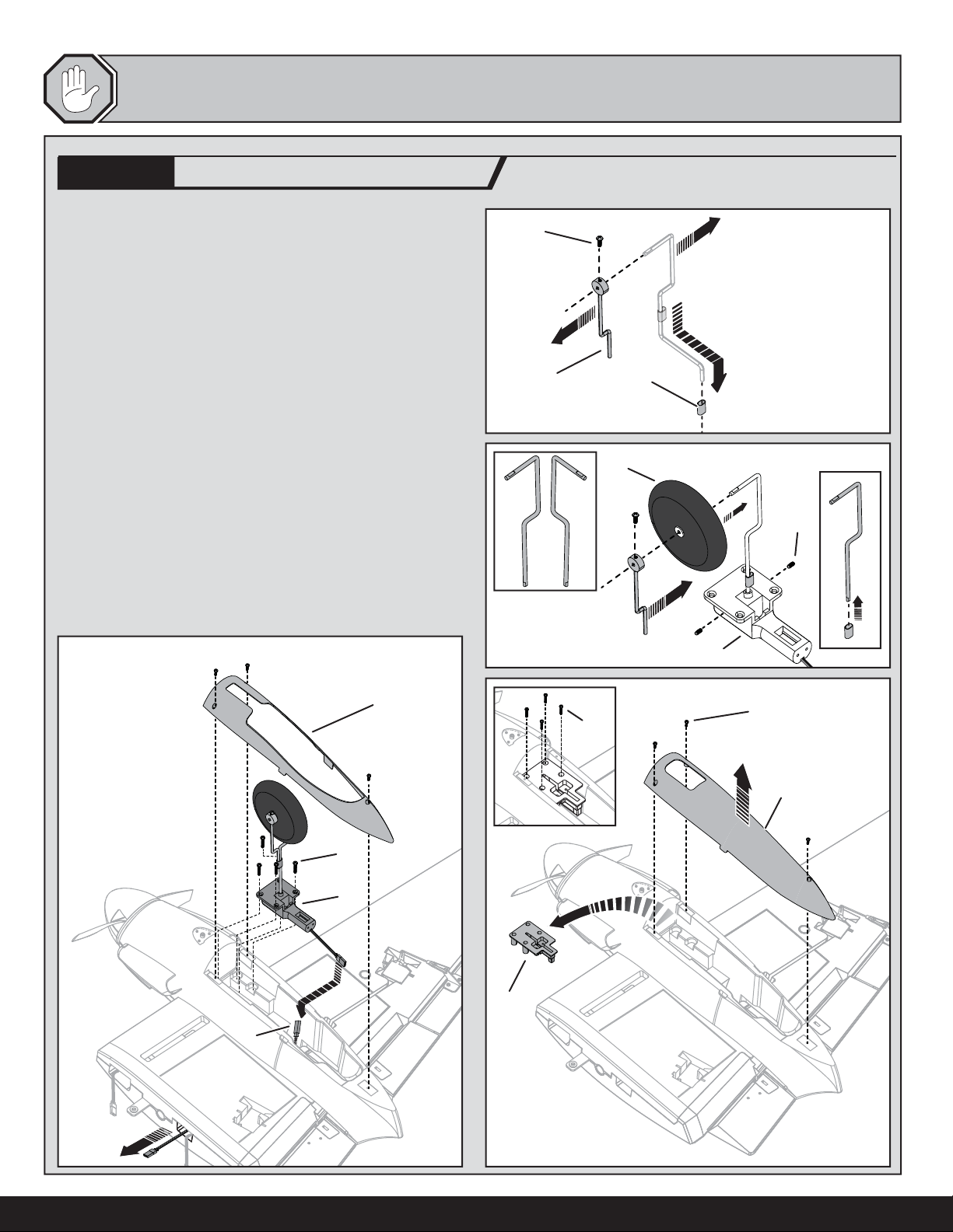
We recommend installing the E-fl ite electric retracts (optional) in the wing
before installing the wing on the fuselage.
OPTIONAL
1. Remove the tubes (A), inside struts with wheel collars (B) and screws (C)
from the fi xed left and right struts.
2. Install the wheels (D), inside struts with wheel collars, tubes, and screws
on the retract struts (E).
3. Install the included left and right retract struts in the optional retracts (F)
using the set screws (G).
4. Remove 3 screws (H), the fi xed landing gear cover (I), 4 screws (J) and the
fi xed gear mount (K) from each engine nacelle.
5. Install the retracts (L) in the wing using 8 screws (M) (4 per side) removed
from the fi xed gear mounts.
6. Connect two servo extensions (PKZ5403) (N) to the retract and push the
extension connectors through the channels in the wing and out the holes
used by the aileron connectors.
Tip: Ensure the extended landing gear wheels have no toe-in or toe-out for
proper ground handling.
7. Install the retract covers (O) on the nacelles by using the 6 screws from the
fi xed landing gear covers.
8. Connect the servo extension connectors to a Y-harness in the fuselage.
9. Connect the Y-harness to the GEAR channel of the receiver.
10. Do a control test of the retracts using your transmitter. During operation,
adjust parts so the retracts are not blocked. Tighten the screws in the
wheel collars, using threadlock when needed.
E-fl ite Retractable Landing Gear
(EFLG100, sold separately)
C
AB
D
E
Fixed Landing Gear
Retractable Landing Gear
G
F
O
H
J
I
M
L
K
N
6
 Loading...