

ParkZone PKZ6180 User Manual
Archer
Instruction Manual / Bedienungsanleitung
Manuel d’utilisation / Manuale di Istruzioni
EN
NOTICE
All instructions, warranties and other collateral documents are subject to change at the sole discretion of Horizon Hobby, Inc. For up-to-date product
literature, visit www.horizonhobby.com and click on the support tab for this product.
Meaning of Special Language:
The following terms are used throughout the product literature to indicate various levels of potential harm when operating this product:
NOTICE: Procedures, which if not properly followed, create a possibility of physical property damage AND little or no possibility of injury.
CAUTION: Procedures, which if not properly followed, create the probability of physical property damage AND a possibility of serious injury.
WARNING: Procedures, which if not properly followed, create the probability of property damage, collateral damage, and serious injury OR create a high
probability of superfi cial injury.
WARNING: Read the ENTIRE instruction manual to become familiar with the features of the product before operating. Failure to operate the product
correctly can result in damage to the product, personal property and cause serious injury.
This is a sophisticated hobby product. It must be operated with caution and common sense and requires some basic mechanical ability. Failure to operate this Product in a safe and responsible manner could result in injury or damage to the product or other property. This product is not intended for use
by children without direct adult supervision. Do not attempt disassembly, use with incompatible components or augment product in any way without the
approval of Horizon Hobby, Inc. This manual contains instructions for safety, operation and maintenance. It is essential to read and follow all the instructions
and warnings in the manual, prior to assembly, setup or use, in order to operate correctly and avoid damage or serious injury.
Age Recommendation: Not for children under 14 years. This is not a toy.
Safety Precautions and Warnings
As the user of this product, you are solely responsible for operating in a manner
that does not endanger yourself and others or result in damage to the product
or the property of others.
• Always keep a safe distance in all directions around your model to avoid
collisions or injury. This model is controlled by a radio signal subject to
interference from many sources outside your control. Interference can cause
momentary loss of control
• Always operate your model in open spaces away from full-size vehicles,
traffi c and people.
• Always carefully follow the directions and warnings for this and any optional
support equipment (chargers, rechargeable battery packs, etc.).
• Always keep all chemicals, small parts and anything electrical out of the
reach of children.
• Always avoid water exposure to all equipment not specifi cally designed and
protected for this purpose. Moisture causes damage to electronics.
• Never place any portion of the model in your mouth as it could cause serious
injury or even death.
• Never operate your model with low transmitter batteries.
• Always keep aircraft in sight and under control.
• Always use fully charged batteries.
• Always keep transmitter powered on while aircraft is powered.
• Always remove batteries before disassembly.
• Always keep moving parts clean.
• Always keep parts dry.
• Always let parts cool after use before touching.
• Always remove batteries after use.
• Always ensure failsafe is properly set before fl ying.
• Never operate aircraft with damaged wiring.
• Never touch moving parts.
Battery Warning
The Battery Charger included with your aircraft is designed to safely balance and charge the Li-Po battery.
CAUTION: All instructions and warnings must be followed exactly. Mishandling of Li-Po batteries can result in a fi re, personal injury, and/or property damage.
• By handling, charging or using the included Li-Po battery, you assume all
risks associated with lithium batteries.
• If at any time the battery begins to balloon or swell, discontinue use immediately. If charging or discharging, discontinue and disconnect. Continuing
to use, charge or discharge a battery that is ballooning or swelling can result
in fi re.
• Always store the battery at room temperature in a dry area for best results.
• Always transport or temporarily store the battery in a temperature range of
40–120º F (5–49º C). Do not store the battery or aircraft in a car or direct
sunlight. If stored in a hot car, the battery can be damaged or even
catch fi re.
• Always charge batteries away from fl ammable materials.
• Always inspect the battery before charging and never charge
damaged batteries.
• Always disconnect the battery after charging, and let the charger cool
between charges.
• Always constantly monitor the temperature of the battery pack
while charging.
• ONLY USE A CHARGER SPECIFICALLY DESIGNED TO CHARGE LI-PO BATTERIES. Failure to charge the battery with a compatible charger may cause fi re
resulting in personal injury and/or property damage
• Never discharge Li-Po cells to below 3V under load.
• Never cover warning labels with hook and loop strips.
• Never leave charging batteries unattended.
• Never charge batteries outside recommended levels.
• Never attempt to dismantle or alter the charger.
• Never allow minors to charge battery packs.
• Never charge batteries in extremely hot or cold places (recommended
between 40–120° F or 5–49° C) or place in direct sunlight.
2

– Introduction –
As you’re about to fi nd out, the compact size, scale good looks and no-nonsense fl ight characteristics of the ParkZone® Archer™ aircraft make it excellent company to have around almost anywhere. At home, on the road or on your lunch break, you’ll have no trouble fi nding the time or opportunity to fl y. Assembly couldn’t
be easier. In fact, you’ll probably have it together and ready for its maiden fl ight well before the battery has fi nished charging.
If the Archer is the fi rst sport plane you’ve fl own since soloing a trainer, you’ll fi nd the transition is an easy one. Like most trainers, it has tricycle landing gear
and plenty of dihedral, so you should feel right at home during takeoffs and landings. About the only difference is in the shape of the wing. Unlike the fl at-bottom
airfoils on a lot of high-wing trainers, the semi-symmetrical airfoil makes the aircraft less likely to fl oat and may require a touch more speed on landings. You’ll
want to factor that into your approach profi le as you prepare for that fi rst landing.
Whatever your experience level, though, you must take some time to read this manual. In addition to instructions for fi nal assembly, you’ll fi nd handy setup tips,
important battery charging precautions and a helpful troubleshooting guide. It’s all here to make sure your fi rst fl ight, and every one after it, is as successful as
can be.
Box Contents
Includes
EN
Table of Contents
Charging the Flight Battery ............................................................... 4
Low Voltage Cutoff (LVC) ................................................................... 4
Installing the Transmitter Batteries .................................................... 5
Understanding the Controls of the DX4e Transmitter ......................... 5
DX4e Range Check ........................................................................... 6
Transmitter and Receiver Binding ...................................................... 7
Installing the Battery ......................................................................... 7
Arming the ESC and Receiver............................................................ 8
Installing the Horizontal Stabilizer ..................................................... 9
Control Horn and Servo Arm Settings ................................................ 9
Installing the Wing .......................................................................... 10
Control Surface Centering and Installing Clevises on Control Horns . 10
Installing the Landing Gear ............................................................. 11
Center of Gravity (CG) ..................................................................... 11
Control Direction Test ...................................................................... 12
Specifi cations
36.8 inches (935mm)
25.6 inches (650mm)
Weight: 16.4 oz
(466 g)
Installed Installed 370 Brushless Outrunner Motor, 1300Kv (PKZ6116)
Installed Installed 10-Amp Pro Brushless ESC (EFLA1010)
Installed Installed
Installed Installed
Included Included
Included Included
Needed to
Complete
Dual Rates ...................................................................................... 12
Flying Tips and Repairs ................................................................... 13
First Flight Preparation .................................................................... 13
Maintenance After Flying ................................................................ 13
Removing the Nose Gear Nose Gear Service ................................... 14
Service of Power Components ........................................................ 14
AMA National Model Aircraft Safety Code ........................................ 15
Troubleshooting Guide .................................................................... 16
Limited Warranty ............................................................................ 17
Contact Information ........................................................................ 17
FCC Information .............................................................................. 18
Compliance Information for the European Union .............................. 18
Parts Contact Information ............................................................... 67
Replacement Parts .......................................................................... 67
Optional Parts ................................................................................. 68
(2) Aileron Servos (PKZ1081)
(1) Rudder Servo (1) Elevator Servo (PKZ1080)
Spektrum™ AR400 4-Channel DSM2®/DSMX®
Aircraft Receiver
Battery: 7.4V 2S 1300mAh 20C Li-Po
(EFLB13002S20)
Battery Charger: 2S DC Li-Po balancing charger
(EFLC3125)
DX4e
Included
Recommended Transmitter:
Full-Range 4-Channel 2.4GHz with Spektrum
®
/DSMX® technology.
DSM2
™
To register your product online, visit www.parkzone.com
3
EN
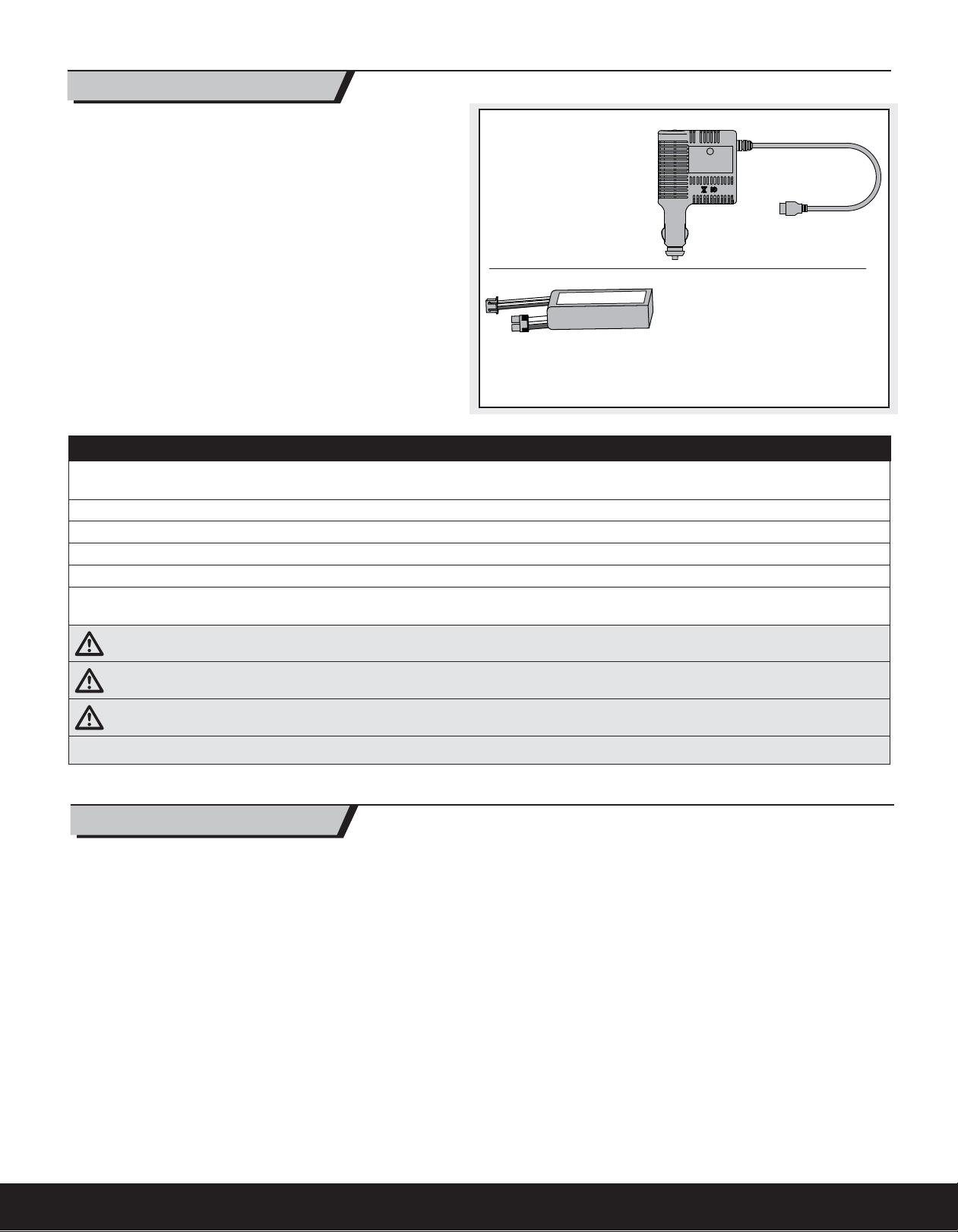
Charging the Flight Battery
Your aircraft comes with a DC balancing charger and 2S Li-Po battery. You
should only charge your battery with the included charger. Never leave the
battery and charger unattended during the charge process. Failure to follow
the instructions properly could result in a fi re. When charging, ensure the battery is on a heat-resistant surface. Charge the fl ight battery while assembling
the aircraft. Install the fully charged battery to perform control tests and
binding.
DC Li-Po Balancing Charger Features
• Balances and charges 2-cell lithium polymer battery packs
• LED charge status indicator
• 12V accessory outlet power cord
Purchase optional 12V adapters (HBZ6513 or HBZ4747) to power your
charger more conveniently.
The Battery Charging Process
1. Charge only batteries that are cool to the touch and are not damaged. Look at the battery to make sure it is not damaged e.g., swollen, bent, broken
or punctured.
2. Insert the charger into the appropriate power supply (12V accessory outlet).
3. Connect the balancing lead of the battery to the charger port.
4. The LED will fl ash during charging.
5. The LED will glow solid when the battery is fully charged. (Approximately 1 hour)
6. Always disconnect the battery from the charger immediately upon completion
of charging. The LED will turn off.
Charger Specifi cations
• Input power: 10–14V
• Charges 2-cell Li-Po packs
with a minimum capacity of
1300mAh
• Maximum charge rate 1C
(1.3 amps)
7.4V 2S 1300mAh 20C Li-Po
(EFLB13002S20)
The E-fl ite
tures a balancing lead that allows you
to safely charge your battery pack when
used with the included Li-Po
balancing charger.
®
2S Li-Po battery pack fea-
CAUTION: Overcharging a battery can cause a fi re.
CAUTION: Only use a charger specifi cally designed to charge a Li-Po battery. Failure to do so could result in fi re causing injury or property damage.
CAUTION: Never exceed the recommended charge rate.
NOTICE: If using a battery other than the included Li-Po battery, refer to your battery manufacturer’s instructions for charging.
Low Voltage Cutoff (LVC)
When a Li-Po battery is discharged below 3V per cell, it will not hold a charge.
The ESC protects the fl ight battery from over-discharge using Low Voltage
Cutoff (LVC). Before the battery charge decreases too much, LVC removes
power supplied to the motor. Power to the motor pulses, showing that some
battery power is reserved for fl ight control and safe landing.
When the motor pulses, land the aircraft immediately and recharge the
fl ight battery.
Disconnect and remove the Li-Po battery from the aircraft after use to prevent
trickle discharge. Charge your Li-Po battery to about half capacity before storage. During storage, make sure the battery charge does not fall below 3V
per cell. LVC does not prevent the battery from over-discharge during storage.
NOTICE: Repeated fl ying to LVC will damage the battery.
4
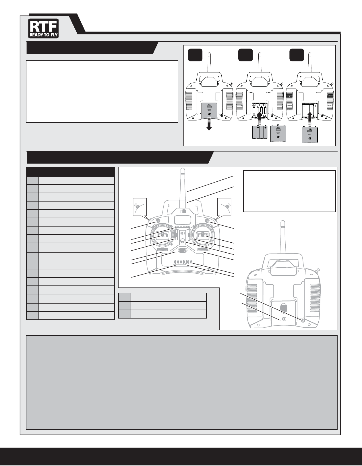
Installing the Transmitter Batteries
1 32
Your Spektrum DX4e comes prebound to the aircraft.
Remove the battery cover, install the four included batteries (noting proper
polarity) and reinstall the battery cover.
Low Battery Alarm
When the battery voltage drops below 4.7 volts, an alarm sounds and the
voltage LEDs fl ash. The batteries must be replaced immediately. If this
happens while fl ying, land your aircraft as soon and as safely as possible.
Understanding the Controls of the DX4e Transmitter
EN
KEY
Antenna
A
Handle
B
Trainer/Bind Button (Modes 1/3 only)
C
Hi/Lo Rate Switch
D
Right Control Stick
E
Trim Slider (for up/down on stick)
F
Neck Strap Connection
G
Trim Slider (for left/right on stick)
H
Mode Switch (1/3 or 2/4)
I
Mix Switch (Elevon only)
J
Servo Reverse Switches
K
Power Switch (ON/OFF)
L
Trim Slider (for left/right on stick)
M
Trim Slider (for up/down on stick)
N
Left Control Stick
O
LEDs
P
ACT/AUX Switch (Channel 5)
Q
* The diagram shows the transmitter controls for Mode 2 and Mode 1 transmitters.
Q
P
O
N
M
L
K
Trainer/Bind Button (Modes 2/4 only)
R
Battery Cover
S
Trainer Port
T
A
For more information on the transmitter, go to
http://www.horizonhobby.com/products/
B
dx4e-dsmx-4-channel-full-range-tx-onlymd2-4-SPMR4400 and click on the support
CR
tab for the Spektrum DX4e to download the
instruction manual.
D
E
F
G
H
I
J
T
S
Trainer/Bind Button ((C) Mode 1 or (R) Mode 2)
The Trainer/Bind Button is used during binding or when connecting a trainer
cord (SPM6805) to the trainer port (T). For complete binding instructions, refer
to the binding section in this manual.
When using the trainer function, connect the trainer cord into the trainer port
in both the master (instructor) and the slave (student) transmitters. The master
transmitter must be powered ON and bound to the receiver. The slave transmitter must be powered OFF. Any time you press and hold the trainer button
on the master, it will give control authority to the slave. Releasing the trainer
button returns control to the master.
IMPORTANT: The slave transmitter must always have the same reverse settings as the master.
Hi/Lo Rate Switch (D)
This switch supports high and low rate functions on aileron, elevator and
rudder channels. In the upper, or “HI” position, servo travel is 100% on these
channels. In the lower, or “LO”, position, servo travel decreases to 70% on
these channels. This switch lets you quickly change control rates from high for
aggressive maneuvers to low for smooth, precise maneuvers. When learning
to fl y, use low rate.
Mode Switch (I)
This switch changes channel assignments to the control sticks. Always ensure
the controls respond as desired before fl ying. A Mode 1 transmitter may be
switched to Mode 3, while a Mode 2 transmitter may be switched to Mode 4.
Mix Switch (J)
This switch enables a mix for elevons on Delta wing aircraft. If needed, refer
to the transmitter manual for more information.
5
EN
Servo Reversing Switches (K)
These switches select the servo direction of each channel. Use your fi ngernail
or a small screwdriver to change the switch position to normal (NOR) or
reverse (REV) as needed to make transmitter controls operate the model as
desired. Perform the Control Direction Test before fl ying.
ACT/AUX Switch (Q)
This switch activates a receiver channel (such as servos) connected through
an AUX channel of the receiver.
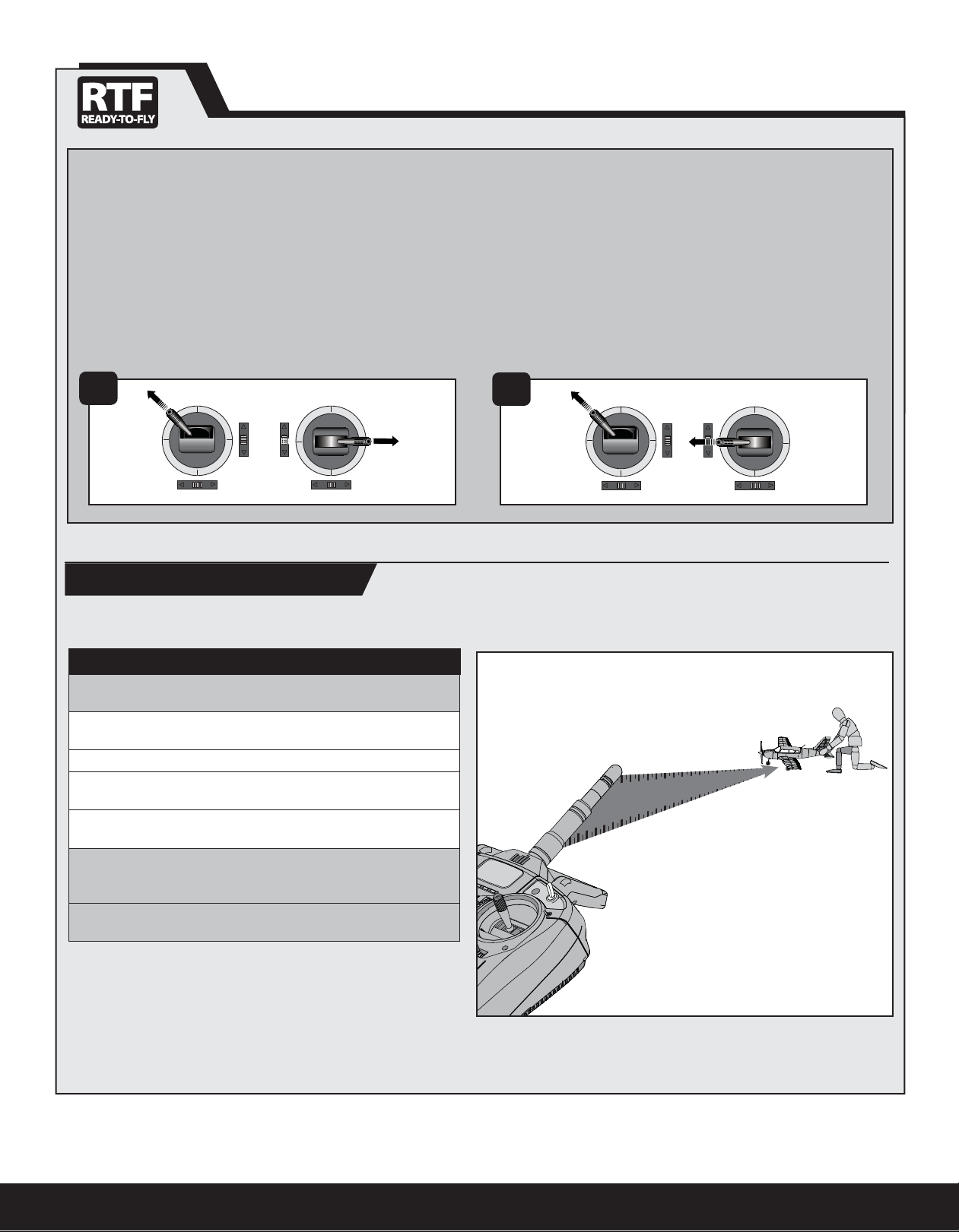
France RF Setting
The DX4e has a France RF setting that complies with French regulations. The
France RF setting should only be turned on when operating your transmitter in
France outdoors.
1
DX4e Range Check
To set France mode (Illustration 1 below):
Push and hold the trainer button on the top of the transmitter while pushing
and holding the two sticks as shown below, then power ON the transmitter.
After hearing a series of descending beep tones (high to low), release the
trainer switch and the sticks. The France setting is now turned on. Bind the
transmitter to the receiver for the change to take effect.
To set Standard mode (Illustration 2 below):
Push and hold the trainer button on the top of the transmitter while pushing
and holding the two sticks as shown below, then power ON the transmitter. After hearing a series of ascending beep tones (low to high), release the trainer
switch and the sticks. The France setting is turned off.
2
Placing the transmitter in RANGE CHECK mode reduces the output power,
allowing a range check.
DX4e Transmitter Range Check Process
Before performing the range check, ensure the correct failsafe stick
positions are established.
1. With the system powered on and the model restrained on the
ground*, stand 90ft/28m away from the model.
2. Face the model with the transmitter in your normal fl ying position.
3. Push and hold the trainer button while toggling the Hi/Lo Rate Switch
four times.
4. The LEDs will fl ash and the alarm will sound. The system is in range
check mode.
IMPORTANT: You must hold the trainer button during the entire range
check process. Releasing the button switch will exit the range check
mode.
You should have total control of the model with the trainer button held at
90ft/28m meters.
*In some aircraft, when the model is placed on the ground, the antenna(s)
can be within inches of the ground. Close proximity of the antenna(s) to the
ground can reduce the effectiveness of the range check. This is called pulling.
If you experience issues during the range check, restrain the model on a nonconductive stand or table up to 2ft (60cm) above the ground. Then range check
the system again.
28 meters (90 feet)
If control issues exist, contact the appropriate Product Support Department for
assistance, or visit the Spektrum website for more information.
6
Transmitter and Receiver Binding
EN
Binding is the process of programming the receiver to recognize the GUID (Globally Unique Identifi er) code of a single specifi c transmitter. You need to ‘bind’ your
chosen Spektrum
of compatible transmitters).
CAUTION: When using a Futaba® transmitter with a Spektrum DSM® module, you must reverse the throttle channel and rebind. Refer to your Spektrum
module manual for binding and failsafe instructions. Refer to your Futaba transmitter manual for instructions on reversing the throttle channel.
* The throttle will not arm if the transmitter’s throttle control is not put at the lowest position. If you encounter problems, follow the binding instructions and
refer to the transmitter troubleshooting guide for other instructions. If needed, contact the appropriate Horizon Product Support offi ce.
™
DSM2®/DSMX® technology equipped aircraft transmitter to the receiver for proper operation (Please visit www.bindnfl y.com for a complete list
Binding Procedure Reference Table (RTF Version: Your Spektrum DX4e comes prebound to the aircraft.)
1. Read the transmitter instructions for binding to a receiver (location of transmitter’s Bind control).
2. Make sure the transmitter is powered OFF.
3. Move the transmitter controls to neutral (fl ight controls: rudder, elevators and ailerons) or to low
positions (throttle, throttle trim).*
4. Install a bind plug in the receiver bind port.
5. Connect the fl ight battery to the ESC. The ESC will produce a series of sounds. One long tone,
then two short tones confi rm that the LVC is set for the ESC.
6. The receiver LED will begin to fl ash rapidly.
7. Power ON the transmitter while holding the transmitter bind button or switch. Refer to your
transmitter’s manual for binding button or switch instructions.
For the DX4e, release the trainer/bind button once the LEDs fl ash and a series of beeps sound.
Within a few seconds, the system should connect.
8. When the receiver binds to the transmitter, the light on the receiver will turn solid and the ESC
will produce a series of three ascending tones. The tones indicate the ESC is armed, provided
the throttle stick and throttle trim are low enough to trigger arming.
9. Remove the bind plug from the bind port.
10. Safely store the bind plug (some owners attach the bind plug to their transmitter using two-part
loops and clips).
11. The receiver should retain the binding instructions received from the transmitter until another
binding is done.
BIND PLUG
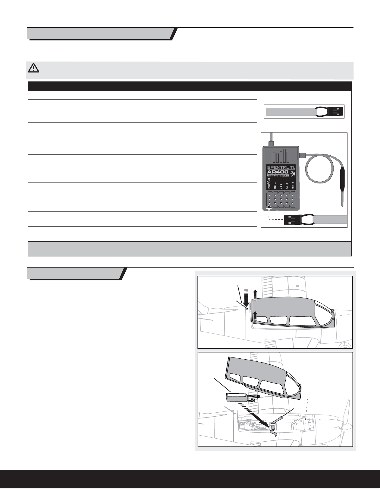
Installing the Battery
1. Push the antenna (A) into the fuselage, releasing the canopy latch.
2. Lift the back of the canopy and pull backwards to remove the canopy.
3. Install the fully charged battery (B) in the battery compartment. See the
Adjusting the Center of Gravity instructions for more information.
4. Make sure the fl ight battery is secured using the hook and loop strap (C).
5. Reinstall the canopy. Push the rear of the canopy securely to ensure the
latch is fully engaged.
A
B
C
7
 Loading...