

Parkwood Maxi, Compact, Insert Service Manual
© Firemakers Limited - (ver4 2013)
Parkwood Pellet Fires
Models Maxi Compact & Insert
Installation Operating & Service Manual
DO NOT INSTALL OR OPERATE THIS FIRE UNTIL THE INSTALLER AND OPERATORS HAVE
ENTIRELY READ THIS MANUAL. FAILURE TO FOLLOW THESE INSTRUCTIONS COULD VOID THE
WARRANTY OR RESULT IN DAMAGE TO THE FIRE.
Private Bag 9038, Wanaka
NEW ZEALAND 9343
Ph: 64 (03) 4432965
0800 PARKWOOD
0800 727596
Email: info@parkwood.co.nz
www.parkwood.co.nz

Installation, Operating and Service Manual
For safe installation and operation of your pellet Fire, read and follow the safety instructions on pages 5 & 6 and
throughout the manual.
© 20.3.2011 Firemakers Limited Page 2
TABLE OF CONTENTS
INTRODUCTION .............................................................................................................................................................................. 4
GLOSSARY ........................................................................................................................................................................................ 4
SAFETY NOTES ............................................................................................................................................................................... 5
FIRE DESCRIPTION ....................................................................................................................................................................... 7
SPECIFICATIONS ............................................................................................................................................................................ 7
FUEL SPECIFICATIONS ............................................................................................................................................................... 8
SAFETY & RATING LABEL LOCATIONS .................................................................................................................................. 9
PELLET FIRE ASSEMBLY............................................................................................................................................................. 9
REMOVING THE FIRE FROM THE PALLET .............................................................................................................................. 9
PEDESTAL HEARTH ASSEMBLY ............................................................................................................................................... 9
DOOR COVER ASSEMBLY ........................................................................................................................................................ 10
INSTALLATIONS ........................................................................................................................................................................... 11
INSTALLATION PRECAUTIONS .............................................................................................................................................. 11
Electrical Information ................................................................................................................................................................ 11
Seismic Restraints ...................................................................................................................................................................... 11
Air Supply Considerations 12
POSITIONING OF THE PELLET FIRE ....................................................................................................................................... 12
DESIGNING A FLUE ................................................................................................................................................................... 12
Restrictive Flue Designs ............................................................................................................................................................ 12
INSTALLATION CONFIGURATIONS ....................................................................................................................................... 13
FREE STANDING INTERNAL VERTICAL INSTALLATION .................................................................................................. 13
Free Standing Internal Vertical Installation Diagram .............................................................................................................. 13
Free Standing Internal Vertical Installation Instructions .......................................................................................................... 13
FREE STANDING EXTERNAL VERTICAL INSTALLATION ................................................................................................. 14
Free Standing External Vertical Installation Instructions ......................................................................................................... 14
Free Standing External Vertical Installation Diagram .............................................................................................................. 15
FREE STANDING SAFE CLEARANCES ................................................................................................................................ ............... 15
FIREPLACE INSERT INSTALLATION ...................................................................................................................................... 16
Fire Place Insert Installation Instructions ................................................................................................................................. 16
Fire Place Insert Installation Diagram ...................................................................................................................................... 16
Fire Place Insert Safe Clearances ............................................................................................................................................. 17
INSTALLERS FLUE INSTRUCTIONS........................................................................................................................................ 18
WALL THERMOSTAT INSTALLATION ................................................................................................................................... 19
PELLET FIRE COMPONENTS .................................................................................................................................................... 20
CONTROL PANEL DISPLAY ....................................................................................................................................................... 21
CONTROL PANEL DISPLAY FUNCTIONS ............................................................................................................................... 21
OPERATING MODES .................................................................................................................................................................... 22
STARTING MODE ....................................................................................................................................................................... 22
RUNNING MODE ......................................................................................................................................................................... 22
STOPPING MODE ........................................................................................................................................................................ 22
PRE-OPERATION NOTES ............................................................................................................................................................ 22
OPERATING PROCEDURES – DAMPER MODELS................................................................................................................ 23
STARTING PROCEDURE ........................................................................................................................................................... 23
NORMAL OPERATING PROCEDURE ....................................................................................................................................... 24
STOPPING PROCEDURE ............................................................................................................................................................ 24

Installation, Operating and Service Manual
For safe installation and operation of your pellet Fire, read and follow the safety instructions on pages 5 & 6 and
throughout the manual.
© 20.3.2011 Firemakers Limited Page 3
OPERATING PROCEDURES – DAMPERLESS MODELS ...................................................................................................... 24
STARTING PROCEDURE ......................................................................................................................................................... 234
NORMAL OPERATING PROCEDURE ..................................................................................................................................... 245
STOPPING PROCEDURE .......................................................................................................................................................... 245
COMBUSTION AIR AND AIR DAMPER ROD ADJUSTMENTS damper models only ........................................................ 25
INSUFFICIENT AIR ..................................................................................................................................................................... 26
TOO MUCH AIR ........................................................................................................................................................................... 26
CLINKER & ASH BUILD UP ....................................................................................................................................................... 26
SETTING THE TIME AND USING THE CONTROL SWITCHES ......................................................................................... 27
SETTING THE TIME .................................................................................................................................................................... 27
SETTING THE ON TIME ............................................................................................................................................................. 27
SETTING THE OFF TIME............................................................................................................................................................ 27
PELLET FEED .............................................................................................................................................................................. 28
THERMOSTAT ............................................................................................................................................................................. 28
DAILY MAINTENANCE ............................................................................................................................................................... 28
WEEKLY MAINTENANCE .......................................................................................................................................................... 29
ANNUAL MAINTENANCE ........................................................................................................................................................... 29
TROUBLE SHOOTING ................................................................................................................................................................. 30
FUSES ........................................................................................................................................................................................... 30
FUSE LOCATION DIAGRAM ..................................................................................................................................................... 31
PELLET FUEL QUALITY ............................................................................................................................................................ 31
FUEL FEED PROBLEMS ............................................................................................................................................................. 32
POOR PERFORMANCE OF THE FIRE ....................................................................................................................................... 32
IGNITION PROBLEMS ................................................................................................................................................................ 32
PCB. CONTROLLER .................................................................................................................................................................... 33
FREQUENTLY ASKED QUESTIONS ......................................................................................................................................... 33
NO FUEL ................................................................ ................................................................ ................................ ....................... 33
E FAIL ........................................................................................................................................................................................... 34
WARRANTY .................................................................................................................................................................................... 35
Keep this Manual and the Certificate of Compliance issued by the
Installer / Council in a safe place for future reference or any future warranty claims.
Parkwood reserves the rights to any carbon credits associated with this product.
Pellet Fuel Facts
Because of their density, wood pellets require a vacuum to burn in and they will not combust outside of a vacuum
chamber. Hence, pellets will only smoulder and create considerable amounts of smoke outside of a vacuum
chamber.
During safety testing, accelerants such as methylated spirits or petrol accelerants are poured into a hopper full of
pellets and ignited, once the accelerant has burned off, only smouldering pellets remain. The pellets will not
spontaneously combust and burn like other solid fuels.
Wood pellets will not burn on an open fire; they will smother the fire, deprive the fire of oxygen and effectively put
the flames out.
Pellet fires are acknowledged as being that safe that in some States of the US homeowners incur a lower
insurance premium if they have a pellet fire. In addition, piles of firewood around dwellings are considered a fire
risk. Insurance companies acknowledge that pellet fuel mitigates this risk.

Installation, Operating and Service Manual
For safe installation and operation of your pellet Fire, read and follow the safety instructions on pages 5 & 6 and
throughout the manual.
© 20.3.2011 Firemakers Limited Page 4
INTRODUCTION
This is a detailed Manual that will ensure the safe and proper installation and operation of your Parkwood Pellet Fire.
Please ensure that the Installer and all Operators:
1. Read and familiarise themselves with the Entire Manual and Safety Notes.
2. Follow the Installation, Precautions, Installation and Operating Instructions.
3. Follow the Pre-operation Notes, Starting, Operating and Shutdown Procedures.
WARNING: If the instructions in this manual are not followed exactly, a fire or electrocution may result causing property
damage, personal injury or loss of life.
GLOSSARY
The following terms are used in this manual.
Hopper
This is the fuel storage area on the top of the Fire. Always keep the hopper at least ¼ full.
Auger
The fuel delivery mechanism.
Burn Pot Liner
The removable liner that the pellets burn in after being fed from the hopper.
Burn Pot
The receptacle that the Burn Pot Liner rests in.
Burn Pot Ash Slide
A device by which ash can be removed from the burn pot by sliding the plate in and out using a handle located
on the left side panel
Ash
The spent residual product of combustion.
NOTE: The ash content of the fuel and operation of your Fire will directly determine the frequency of cleaning.
The use of high ash content fuels may result in the fire needing to be frequently cleaned. A low ash content
fuel will allow longer intervals between cleaning.
Clinker
Clinker is silica (sand) or other impurities in the fuel that will form a hard mass in the Burn Pot Liner during the
burning process.
Fly ash
About one third of the ash produced is blown around the inside of the Firebox and exhaust system.
Creosote
Is a black tar like buildup produced by high water content pellets or incomplete combustion.
Carbon
A product of poor combustion visible as layer of fine black soot.
Safe Clearances
The distance required to maintain a safe operating distance from the fire to a combustible material.
Rating Label
A label inside the hopper lid that shows all ratings and certifications including the Serial Number and Model of
the Fire.
Air Damper Rod
Is a device used to adjust the amount of combustion air supplied to the Fire to achieve an efficient heat output.
Flue
Is an approved pipe made of a stainless steel inside liner and galvanized outer pipe, which vents products of
combustion to the atmosphere. It can also be a stainless flexible pipe for Fireplace Insert applications.
Magnehelic Pressure
This is the vacuum (Negative pressure) in the Firebox, which is created by the Exhaust Fan and regulated with
the Air Damper Rod.
Pellet Fire Components
Refer to the detailed Pellet Fire Components on page 20.

Installation, Operating and Service Manual
For safe installation and operation of your pellet Fire, read and follow the safety instructions on pages 5 & 6 and
throughout the manual.
© 20.3.2011 Firemakers Limited Page 5
SAFETY NOTES
PLEASE READ ALL OF THIS MANUAL AND THE SAFETY NOTES BEFORE INSTALLING AND OPERATING THE
FIRE.
Parkwood Pellet Fires are different from conventional wood burning appliances. It is very important that you read and
understand all of the instructions before installing and using the Fire. Follow the procedures and instructions outlined in
this manual exactly. Failure to follow instructions may result in damage to the Fire, property damage, bodily injury, or
even death. It is recommended that you have your Fire installed by an authorised Parkwood Pellet Fires Distributor or
at least have them inspect the installation. A qualified installer must install this Pellet Fire.
1. Parkwood Pellet Fires assumes no responsibility for poor Fire performance or consequential damage resulting from
installations that do not comply with the instructions detailed in this Manual.
2. Fill out the Warranty Registration Card included with your Fire. Send the Warranty Registration Card directly to
Parkwood Pellet Fires within 30 days of purchase to register your Warranty.
3. This Fire will not operate using natural draft or without a power source for the blowers and fuel feeding system.
4. Never attempt to repair any part of the Fire unless following the instructions in this manual. A qualified installer or
service technician must carry out installation and repairs. Any panels or parts removed for servicing must be replaced
prior to operating the Fire.
5. Any modifications to the Fire, unless authorised by Parkwood Pellet Fires, could be dangerous and will void the
warranty of the Fire.
6. This Fire must be connected to an earthed standard 240-volt 50 Hz electrical outlet. Parkwood Pellet Fires
recommends that a power surge protector be fitted.
7. NEVER cut or remove the grounding prong from the power cord plug.
8. ALWAYS wait until the Fire has entirely cooled and disconnect the power before performing any maintenance.
9. NEVER place combustible objects (Clothing etc) on or near your Fire.
10. NEVER allow children near the Fire during operation, and do not allow anyone to operate the Fire who is unfamiliar
with these instructions.
11. Children and adults should be alerted to the hazards of high surface temperatures and people should stay away to
avoid burns or clothing ignition. Fit a Fire safety guard around the Fire if children are present.
12. ALWAYS keep the hopper at least ¼ full.
13. NEVER connect this Fire to a chimney or flue serving another appliance.
14. ALWAYS follow the Starting and Stopping instructions in this manual; short cuts of any kind can be dangerous.
15. Check your local Building and Fire codes, regulations and requirements before installing your Fire.
16. NEVER unplug the Fire when it is operating, always turn the fire off with the switch and allow the fire to complete
the shutting down mode.
17. When disposing of ash accumulations from the Fire, always place them in a metal container with a tight fitting lid.
The closed container must be placed on a noncombustible surface well away from all combustible materials, pending
final disposal. The ashes should be retained in the closed container until all cinders have thoroughly cooled.
18. Any fireguard, safety screen or panel removed for servicing the Fire must be replaced prior to operating the Fire.
19. Your Fire is designed and approved for burning Premium Quality 6mm palletized wood pellet fuel, which meets or
exceeds AS/NZS 4014.6 2007. Burning of any other fuel or materials is not permitted. Failure to comply with this

Installation, Operating and Service Manual
For safe installation and operation of your pellet Fire, read and follow the safety instructions on pages 5 & 6 and
throughout the manual.
© 20.3.2011 Firemakers Limited Page 6
restriction will void all warranties and the safety listing of the Fire. Poor quality fuel will directly (and adversely) affect
efficiency and cleanliness of your Fire’s operation. Refer to Pellet Fuel Quality on page 30.
20. NEVER use petrol, petrol type fuel, kerosene, lighter fluid or similar liquids to start or “freshen up” this Fire. Do not
store or use petrol or other flammable vapors and liquids in the vicinity of the Fire.
21. INSTALL a smoke detector within the proximity of your pellet Fire.
22. NEVER put foreign objects in the hopper. NEVER burn rubbish or unapproved fuel or material in this Fire.
23. NEVER obstruct free airflow through air vents or the flue.
24. Do not place unburned or raw pellet fuel in the ash pan. A Fire in the ash pan or excess emissions may occur.
25. This Fire’s exhaust system works with a negative combustion chamber pressure (vacuum) and a low positive
chimney pressure. It is very important that the exhaust system be completely airtight and properly installed. The
chimney joints should overlap at least 40mm, be sealed with RTV 260 degrees Celsius (500 F) silicone sealant and
secured with at least 3 sheet metal screws.
26. Never attempt to operate this Fire without the Burn Pot Liner in place.
27. CARBON AND FLY ASH: The products of combustion will contain small particles of fly ash. The fly ash will collect
in the Firebox and exhaust system. Fly ash will restrict the flow of the flue gases. Incomplete combustion, such as
occurs during start-up, stopping, or incorrect operation of the Fire will lead to some soot formation which will collect in
the exhaust system. The exhaust system should be inspected at least once every year for any buildup of ash; soot or
creosote to determine if cleaning is necessary.
28. The Burn Pot Ash Slide, Ash Pan and Firebox door must be closed securely for proper and safe operation of the
Fire. Also ensure all gaskets checked annually and replaced when necessary.
29. Do not abuse the glass by striking it or slamming the door. Do not attempt to operate the Fire with broken glass.
The Fire has 5mm Pyroceramic glass. Replacement glass must be purchased from a Parkwood Pellet Fires
Distributor. To clean the glass, use a dampened, paper towel, or tissue. Always dampen with water only. For difficult to
remove stains, dip the dampened cloth into some ash from the ash pan. NEVER use abrasive cleaning agents or
chemicals on the glass.
30. Always unplug the Fire from the power supply when the Fire is not being used for prolonged periods.
31. Do not operate aerosol sprays or flammables in the vicinity of the Fire while it is in operation
32. Do not place hands at the bottom of the Hopper because moving parts may cause injury.
33. ALWAYS carry out annual maintenance.

Installation, Operating and Service Manual
For safe installation and operation of your pellet Fire, read and follow the safety instructions on pages 5 & 6 and
throughout the manual.
© 20.3.2011 Firemakers Limited Page 7
FIRE DESCRIPTION
The Parkwood range of Pellet Fires is designed to sit on a Hearth Pad Pedestal (on combustible surfaces) as a
freestanding Fire or can be installed as a Fireplace Insert with Surround Panels. A Control Panel is located at the top
right rear of the Fire. The controls include 5 heat settings, On/Off Timers and an On/Off switch and lights to indicate
proper operation. Above the glass Firebox front door are Heat Vanes through which hot room air is blown by the room
air Convection Blower. The Heat-Setting switches will vary the speed of the room air convection blower and increase or
decrease the amount of fuel delivered to the Fire. On the back of the Fire a 75mm exhaust pipe protrudes from the
Combustion Air Blower, the Flue is connected to the exhaust pipe via a Cleanout Tee. The Air Damper Rod located on
the lower right side panel regulates combustion airflow. The front top of the Fire lifts up for easy loading of fuel.
1. Parkwood Pellet Fires are simple and safe to use. A relatively small amount of fuel is burned in an extremely efficient
firebox to provide a constant even heat.
2. The fuel is poured into the Hopper. After the Fire has been turned on (see “Starting” procedure) the Auger Motor
delivers fuel down the Pellet Feed Chute a few pellets at a time, into the Burn Pot Liner at a controlled rate. Hot air from
an electric element is blown onto the fuel until the fuel spontaneously combusts after 4-8 minutes. The Exhaust Fan
delivers combustion air to the Burn Pot creating an efficient burn. The hot exhaust gases are drawn through Heat
Exchangers, which extract heat from the gases as they are discharged to the exhaust flue.
3. The room air Convection Blower circulates room air through the Heat Exchangers located just above the Fire Box
Door. The room air Convection Blower is intended to run continuously and is controlled by the Heat Up/Down switch;
this ensures that constant temperatures can be maintained.
4. The Air Damper Rod is used to adjust the amount of combustion air supplied to the Fire to achieve an efficient heat
output.
5. The Burn Pot Ash Slide is used to remove ash from the Burn Pot and deposit it in the Ash Pan.
6. The Fire will deliver a constant amount of heat, which can be varied by adjusting the Heat “Up” & “Down” switches.
Besides initial lighting of the Fire, the only regular attention needed will be to fill the Hopper with fuel; inspection of the
Burn Pot Liner for “Build up of pellets” or “clinkering” and adjusting the Air Damper Rod as required. Refer to
Combustion Air and Air Damper Rod adjustments on page 24.
SPECIFICATIONS
Maxi Compact Insert
FUEL CAPACITY 50 Kg 23Kg 23Kg
WEIGHT OF COMPLETE UNIT 121Kg 99Kg 99Kg
MAXIMUM HEAT OUTPUT 10.5Kw 10Kw 10Kw
AREA HEATED* 190m² 185m² 185m²
FIRE HEIGHT ON PEDESTAL 895mm 630mm 630mm
FIRE HEIGHT OFF PEDESTAL 870mm 605mm 605mm
FIRE WIDTH 535mm 535mm 535mm
FIRE DEPTH 610mm 610mm 610mm
HEARTH PEDESTAL** 25 x 585 x 795mm (H x W x D)
INSERT SURROUND -750 x 1000 x 20mm (H x W x D)
OVERSIZE SURROUND 850 x 1198 x 20mm (H x W x D)
FLUE OUTLET HEIGHT*** 270mm 240mm 240mm
THERMOSTAT COMPATIBLE Optional on all Parkwood Fires
FLUE TYPE 100mm outer flue with 75mm stainless steel inner liner
ELECTRICAL 240 Volts, 5 Amps, 50 Hz
SAFE CLEARANCES to combustibles:
SIDES 200mm 200mm 200mm
BACK 75mm 75mm 75mm
TOP TO COMBUSTIBLE 290mm 290mm 325mm
FLOOR PROTECTION** 150mm 150mm 150mm
DOUBLE SKIN FLUE 25mm 25mm 25mm
SINGLE SKIN FLUE 75mm 75mm 75mm
INSERT CAVITY CLEARANCES 610 x 600 x 500mm (H x W x D)
Installation, Operating and Service Manual
For safe installation and operation of your pellet Fire, read and follow the safety instructions on pages 5 & 6 and
throughout the manual.
© 20.3.2011 Firemakers Limited Page 8
*Area Heated will vary considerably with the floor plan, house layout & construction and heat loss of the house.
** A Hearth Pedestal or other hearth/floor protection is not required if the Fire is positioned on a non-combustible surface
(Tiles/slate) protruding 150mm forward of the Firebox door opening.
*** Note: Flue Outlet Heights are to the centre of the 75mm outlet. Add 25mm for a hearth pedestal if fitted. Flue Outlets are
off set to the left of the Fire (looking from the front) 148mm.
The floor protection on the sides of the Fire only has to extend to the vertical side panels of the Fire.
FUEL SPECIFICATIONS
Pellet quality is very important for the efficient operation of your Fire, please read the following information:
This Fire has been designed to burn 6mm Premium Quality Wood Pellets only. Do not use any other type of fuel, as
this will void any warranties stated in this manual. The performance of your Fire is greatly affected by the type and
quality of wood pellets being burned. Because the heat output and ash content of various quality wood pellet fuel
differs, this will considerably affect the performance and heat output of Fire. Parkwood Pellet Fires recommend that
you burn only premium quality wood pellet fuel. Poor quality pellet fuel will result in excessive amounts of ash in the
Burn Pot Liner, less than normal heat output and the firebox becoming black with carbon. Refer to Pellet Fuel Quality
on page 30 for proper fire operation when poor quality fuel is being used.
It is important to select and use only pellets that are dry and free of dirt or any impurities such as high salt or silica
content. Dirty fuel will adversely affect the operation and performance of the unit and will void the warranty.
We recommend the use of pellets that meet or exceed AS/NZS 4014.6 2007 as listed below.
FUEL TYPE: Premium Grade Residential Fuel:
Heat Content: 18 to 21 MJ/kg (8200 BTU/lb. Min)
Bulk Density: Not less than 0.64kg / L (40 lb /cubic ft. min)
Moisture Content: 4 - 8% max
Ash Content: Not greater than 0.8% (oven dry basis)
Size: 6mm diameter
Fines: 1% max through 3.2mm screen
NOTE: Pellet Fuel is hydroscopic and it will absorb moisture from the air. Pellet Fuel bags are not airtight or
waterproof. Pellet Fuel should be stored off the ground (on a pallet or plastic sheet) in a dry area that is not
exposed to the elements.
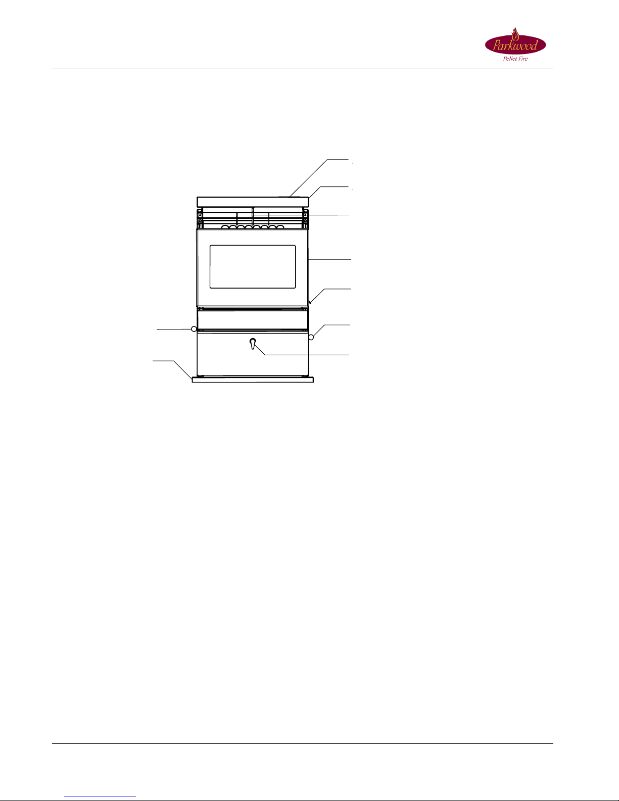
HE A T
EXCHANGE
CLEANING HANDLE
AIR DAMPER
ASH P AN L
A
TC H FIRE BOX DOOR HANDLE
FIRE BOX DOOR
HOPPER LID
CONTRO
L P ANE L BURN PO
T
ASH SLIDE
PEDES
T A L
FRONT VIEW
Installation, Operating and Service Manual
For safe installation and operation of your pellet Fire, read and follow the safety instructions on pages 5 & 6 and
throughout the manual.
© 20.3.2011 Firemakers Limited Page 9
SAFETY & RATING LABEL LOCATIONS
The Rating Label is located inside the Hopper lid.
1. Each Fire has a serial number fixed to the Rating Label attached to the inside of the Hopper Lid. Record the serial
number and the Installers Registration Number on the Warranty Registration Card and post it to Parkwood Pellet Fires
within 30 days of the installation to register your warranty.
2. A label inside the Hopper Lid warns that the Fire is hot. See the safety section of this Manual for more safe operating
tips.
3. Information and warning labels are located inside the hopper lid. These labels provide information on operation and
maintenance that the operator should always follow when operating the Fire. Keep the Hopper Lid closed during
operation.
4. There are electrical warning labels inside the Fire that warn the Operator and Service Technicians, to disconnect the
Fire from the power before servicing. Also, the warning labels inform the Operator and Service Technicians that the
Fire should not be operated with the panels removed.
PELLET FIRE ASSEMBLY
REMOVING THE FIRE FROM THE PALLET
1. Remove all packaging.
2. There are 2 brackets fixing the Fire to the pallet. Use an 8mm socket to remove the brackets. These brackets
may be used as seismic restraints.
3. Clean and remove all marks from any plated Door Covers or Ash Sills before initial firing or they will
permanently mark the plated surface.
PEDESTAL HEARTH ASSEMBLY
1. Carefully place the back of the Fire on the wood pallet that the fire was supplied on.
2. Using an 8mm socket, install the four (4) bolts supplied with the Pedestal Hearth in the holes on the bottom of the
Fire Base plate. Ensure that the supplied lock washers are fitted and leave the bolt heads about 5mm out.
3. Drop the Hearth Pad Pedestal onto the bolts and lock into the correct keyhole position before tightening the bolts.
4. Taking care not to damage the rear of the Pedestal Hearth (or the floor surface), stand the Fire upright and place the
fire in position. An upside down carpet mat is helpful to shift the fire and prevent damage to floor surfaces.
Installation, Operating and Service Manual
For safe installation and operation of your pellet Fire, read and follow the safety instructions on pages 5 & 6 and
throughout the manual.
© 20.3.2011 Firemakers Limited Page 10
NOTE: Parkwood Fires can be installed on a combustible floor using the Pedestal Hearth Pad (for example, linoleum
or wooden flooring). A Pedestal Hearth Pad is not required if a non-combustible surface (Tiles/Slate) protrudes 150mm
forward of the Fire Box Door opening. A non combustible pad (Available from Parkwood) may be used to extend and
existing hearth to the required 150mm.
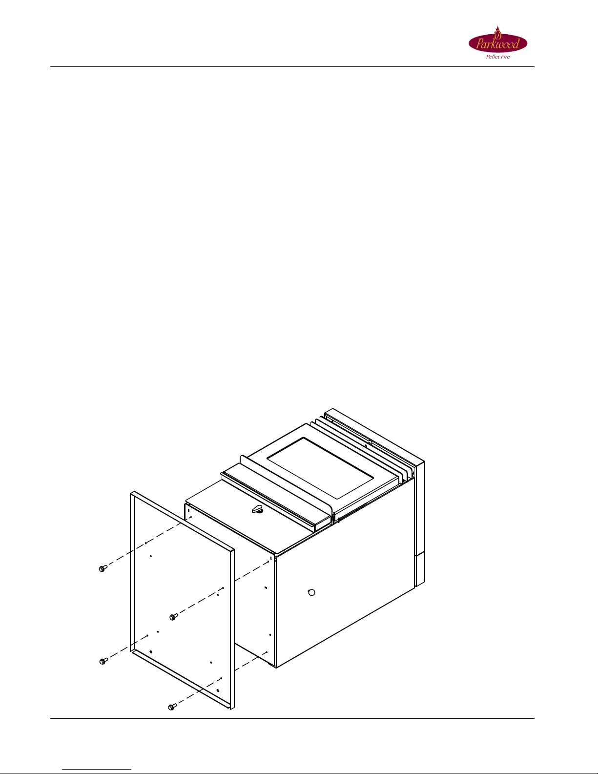
DOOR COVER ASSEMBLY
1. Lay the Plated Door Cover face down on a soft surface.
2. Remove the door by lifting it straight up and off of its hinge pins.
3. Use a M5 tap to thread the 4 holes on the firebox door (where illustrated – SCREW x 4) and fit the M5 Allen head
screws that are supplied with the Door Cover. Ensure they do not protrude through the firebox door.
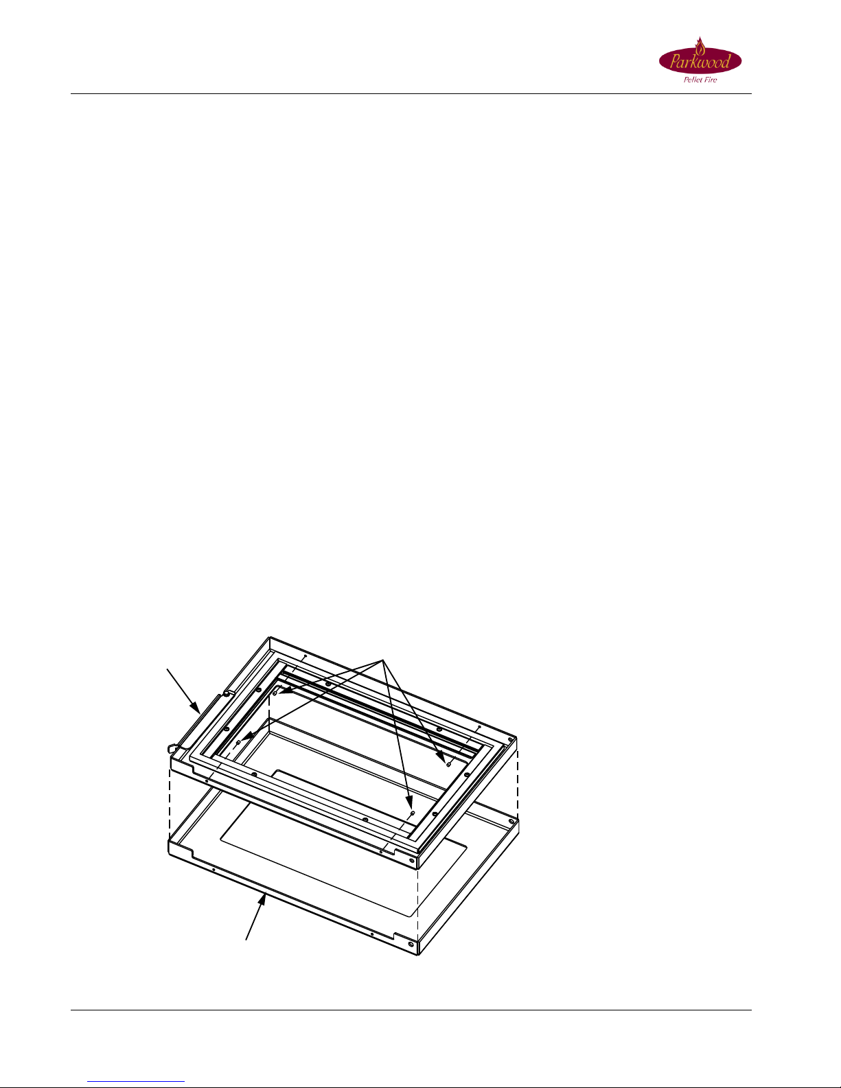
4. Run a thin bead of high temp silicone on the inside of the Door Cover about 20mm from the inside corner edge.
5. Orientate the Door facedown above the Plated Door Cover so that the Door Hinge cutouts align with the Door Hinge
holes then gently lower the Door inside the Plated Door Cover.
6. Ensure that the Door is firmly home and correctly positioned firmly inside the Plated Door Cover by inspecting the
clearance between the mating surfaces when viewing from the front of the Door. There should be no gaps visible
between the mating surfaces.
7. Use an Allen key to tighten the Allen screws to firmly fix the Plated Door Cover to the Firebox Door.
8. The Ash Sill which is located on the fire beneath the firebox door has a ramp on the right side which assists the
firebox door to correctly locate when closing. This ramp must be lowered 3mm by using a shifter/crescent before the
firebox door is fitted to the fire.
9. Fit the Door assembly to the Fire and clean off any marks and fingerprints using a soft cloth to prevent the plating
from becoming permanently marked on initial firing.
PLATED DOOR
DOOR
SCREW x4

Installation, Operating and Service Manual
For safe installation and operation of your pellet Fire, read and follow the safety instructions on pages 5 & 6 and
throughout the manual.
© 20.3.2011 Firemakers Limited Page 11
INSTALLATIONS
INSTALLATION PRECAUTIONS
IMPORTANT: Read all instructions carefully before starting the installation. Failure to follow instructions may result in
damage to the Fire, property damage, bodily injury, or even death.
1. Look at the Instruction Label inside the hopper lid to find the serial number. Write the serial number of the Fire and
the Installers Registration Number on the Warranty Registration Card and post it to Parkwood Pellet Fires within 30
days of the installation. Failure to do so may void your Warranty and will make servicing and maintenance questions
difficult to answer, this could result in needless inconvenience in the future.
2. When installing the Fire:
1. The correct safe clearances must be strictly adhered to.
2. Allow for adequate accessibility for servicing and proper operations.
3. When establishing clearances, measure from any combustible projection, such as; shelves, windowsills,
Fireplace mantles above the appliance, etc.
4. Proper Flue installation is required for safe, reliable operation.
5. Use an upside down carpet mat to slide the fire into position and to prevent floor damage.
DO NOT INSTALL A FLUE DAMPER IN THE EXHAUST FLUEING SYSTEM OF THIS FIRE.
DO NOT CONNECT THIS FIRE TO A CHIMNEY OR FLUE SERVING ANOTHER APPLIANCE.
THIS FIRE MUST BE CONNECTED TO A PROPER FLUE SYSTEM WHILE IN USE.
Electrical Information
The use of a power surge protector is strongly recommended.
If a power point needs to be installed, a qualified Electrician must carry this task out.
Parkwood Pellet Fires are supplied with a three-prong (earthed) plug. The Fire will not operate properly in a non-
compliant improperly earthed electrical outlet. Contact a local electrician to ensure proper electrical power is provided
to the Fire. To avoid any shock hazard, the Fire should be plugged directly into a properly earthed three-prong
receptacle, preferably, a power surge device. Do not cut or remove the earth prong from the plug.
Ensure that the electrical cord is in good condition and is not (or has not been) trapped under the Fire and that it is
clear of any hot surfaces or sharp edges. Inspect the power cord for damage before plugging into a mains supply. If the
power cord becomes damaged, a replacement power cord must be purchased from your Parkwood Pellet Fires
Distributor.
The power cord must remain accessible at all times. To avoid the risk of electric shock, always disconnect the power
cord before servicing the Fire. Never service the Fire with wet hands and replace all panels and components before
operating the Fire. Only qualified technicians should repair possible internal electrical failures.
Seismic Restraints
Check with your local Building Inspectors / Code to determine whether the Fire is required to be bolted to the floor.
Parkwood recommends that all Free Standing Fires are bolted to the floor to prevent accidental movement which may
result in flue seal damage. This is particularly important when fires are positioned on tiles or other smooth surfaces.
Parkwood recommends that Fireplace Insert Fires do not need to be seismically restrained.
Fires mounted on pedestal hearths can be restrained by using the two (2) 10mm holes at the rear of the fire. The
brackets which fixed the Fire to the wood pallet (Fixing Brackets) may be used as seismic restraints. On Insert models,
Fixing Brackets can also be attached to the sides of the Fire Base Plate by using the holes located behind the FPI
Surround Panels or a chain can be attached to the fire using a “D” shackle in one of the redundant Fuse Holders on the
rear of the Fire Base Plate.

Installation, Operating and Service Manual
For safe installation and operation of your pellet Fire, read and follow the safety instructions on pages 5 & 6 and
throughout the manual.
© 20.3.2011 Firemakers Limited Page 12
Air Supply Consideration
1 Parkwood fires draw air from the room to provide oxygen to the fire. Due consideration must be given to where the
air will come from. Many old houses are draughty with gaps round windows or doors etc. Air flow with such houses
is not usually a problem. Modern newer homes however can be tightly sealed and the heater can be starved of air
if all the windows and doors are closed and there are no other vents. This can be exacerbated if there is an
extractor fan running in the house at the same time so that the heater is fighting for air.
2 It is important to realise that the flue for the fire is a vent to the outside and problems may occur if extractor fans
are used in a kitchen or bathroom in a tightly sealed house if there is no other access point for air. Such extractor
fans can cause damp air from outside the home to be drawn through the fire when the fire is not in use. Outside
air can be damp or salt laden if the property is near the sea and can cause corrosion in the firebox if drawn down
the flue. Failure to prevent back venting through the heater will void the warranty on the firebox.
POSITIONING OF THE PELLET FIRE
1. Position the Fire in a large open room that is centrally located in the home. Direct the Fire so that the Convection
Fan will blow hot air into the area that requires heating. For example:
Try not to position the Fire so that the Convection Fan blows air into a wall or opposite an exterior door.
If possible, position the Fire on an exterior wall and direct the Fire to an interior door so that the Fire will firstly
heat the principal room, then fan force centrally heat other areas of the home when the interior door is opened.
2. Check clearances from combustibles.
3. Check the location of the power point.
4. You can flue the Fire internally (check for structural beams and trusses where the proposed flue passes through
the ceiling), externally behind the Fire or flue an existing masonry chimney with a 75mm stainless steel inner
flue.
5. All single skin Flue Components must have 75mm safe clearance to combustibles. Double skin flue components
must have 25mm safe clearance to combustibles.
DESIGNING A FLUE
Pellet Fires have more installation options than any other solid fuel appliance. Standard installations are illustrated
below. Variations to the standard installations are perfectly acceptable when considering the following;
All Parkwood Pellet Fires must have a minimum vertical flue length of 1.2m to prevent poor performance of the fire or
smoke entering the room during a power failure.
Once the positioning of the Pellet Fire and the installation type has been established it is important that you design a
flue system that ensures gas velocity and temperatures are maintained. If the flue system is too long, contains
excessive horizontal sections or several elbows, the exhaust fan may not be able to overcome the resistance offered
by the 75mm system and the gasses may cool and form creosote in the flue system before they are vented. The fire
may perform poorly as a consequence of this.
Parkwood strongly recommends that the installation configurations illustrated in this manual are adhered to.
Restrictive Flue Designs
Gas leakage is more likely where the system design or other problems cause high pressure in the flue. Short flue
systems may produce low pressures and less likelihood of leakage. One of the most restrictive aspects of a pellet
flueing system is a horizontal section. Horizontal runs of pellet flue should not exceed 1.2m. Where the flue system
incorporates several elbows or is very long, it may be advisable to increase the diameter irrespective of the equivalent
length calculation. The larger flue will allow the same amount of gas to flow, but at a lower pressure. Also, keep in
mind, that a relatively long system that is all vertical may not be restrictive because of the natural draft assistance.
Refer to an authorised Parkwood Distributor for advanced restrictive flue designs.
 Loading...