

Page 1
IAN 90981
ROUTER POF 1200 A1
OBERFRÄSE
Bedienungs- und Sicherheitshinweise
Originalbetriebsanleitung
ΚΑΘΕΤΗ ΦΡΕΖΑ
Υποδείξει χειρισού και ασφαλεία
Μετάφραση των αυθεντικών οδηγιών λειτουργίας
ROUTER
Operation and Safety Notes
Translation of original operation manual
Page 2

GB / CY Operation and Safety Notes Page 5
GR / CY Υποδείξει χειρισού και ασφαλεία Σελίδα 15
DE / AT / CH Bedienungs- und Sicherheitshinweise Seite 27
Before reading, unfold both pages containing illustrations and familiarise yourself with all functions of the
device.
Πριν ξεκινήσετε την ανάγνωση, ανοίξτε τι δυο σελίδε ε τι εικόνε και εξοικειωθείτε ε όλε τι
λειτουργίε τη συσκευή.
Klappen Sie vor dem Lesen die beiden Seiten mit den Abbildungen aus und machen Sie sich anschließend
mit allen Funktionen des Gerätes vertraut.
Page 3
DC
272625242321
A
B
4
5
6
2
3
7
8
9
13
15
10
11
12
14
16
2
18
17
20
19
5
6
26 222522
29
1
22
30 28
31
Page 4
F
G
E
H
I J
35 3736
32 33 34
40
38 39
42
41
43
Page 5

5 GB/CY
Table of contents
Introduction
Intended use ........................................................................................................................................ Page 6
Features ...............................................................................................................................................Page 6
Scope of delivery ................................................................................................................................ Page 6
Technical Data ....................................................................................................................................Page 7
General safety advice for electrical power tools
1. Workplace safety ........................................................................................................................... Page 7
2. Electrical safety ............................................................................................................................... Page 7
3. Personal safety ................................................................................................................................ Page 8
4. Careful handling and use of electrical power tools .....................................................................Page 8
5. Service ............................................................................................................................................. Page 9
Safety notices specific to routers ........................................................................................................ Page 9
Supplementary Instructions ................................................................................................................. Page 9
Original accessories / tools ................................................................................................................Page 9
Start-up
Router set / Applications ..................................................................................................................... Page 10
Using the router tool ...........................................................................................................................Page 10
Attaching the extractor adapter ......................................................................................................... Page 10
Reducer ................................................................................................................................................ Page 10
Changing the collet ............................................................................................................................. Page 10
Fitting the guide fence .........................................................................................................................Page 10
Operation
Switching on and off ........................................................................................................................... Page 10
Presetting the speed ............................................................................................................................ Page 11
Set the milling depth ...........................................................................................................................Page 11
Readjust the Milling depth .................................................................................................................. Page 11
Set the milling depth with the step stop .............................................................................................Page 11
Milling direction ..................................................................................................................................Page 11
Milling Process ....................................................................................................................................Page 12
Set the copy casing .............................................................................................................................Page 12
Milling with the copy casing ..............................................................................................................Page 12
Milling with a rip fence ....................................................................................................................... Page 12
Milling with a circular compass .........................................................................................................Page 12
Maintenance and Cleaning .............................................................................................. Page 12
Warranty ......................................................................................................................................... Page 12
Disposal ............................................................................................................................................ Page 13
Declaration of conformity / Manufacturer ..........................................................Page 14
Page 6
6 GB/CY
Introduction
Router POF 1200 A1
Introduction
We congratulate you on the purchase of your new
device. You have chosen a high quality product. The
instructions for use are part of the product. They
contain important information concerning safety,
use and disposal. Before using the product, please
familiarise yourself with all of the safety information
and instructions for use. Only use the unit as de
scribed
and for the specified applications. If you pass the
product on to anyone else, please ensure that you
also pass on all the documentation with it.
Intended use
This device is intended to mill grooves, edges, profiles and slots on a wooden, plastic or light surface,
as well as copy milling. This device is not intended
for outdoor use. Any other uses, and / or modifications to the appliance, are deemed to be improper
usage and may result in serious physical injury. Not
for commercial applications.
Features
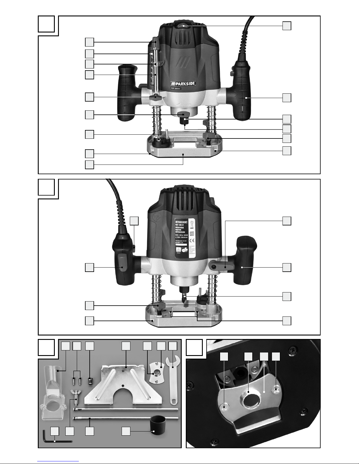
Front view figure A
1
Speed setting
2
Handle
3
Union nut
4
Collet 8 mm (preinstalled in union nut 3)
5
Locking screw
6
Guide rail
7
Base plate
8
Sliding plate
9
Step stop
10
Spindle-lock key
11
Lock screw
12
Depth stop
13
Index indicator
14
Dial milling depth adjustment
15
Control dial (milling depth-fine adjustment)
Back view figure B
16
Clamping lever
17
Router tool
18
Drilling extractor adapter
19
ON / OFF switch
20
Start lockout
Parts figure C
21
Extractor
22
Screw
23
Collet 6 mm
24
Rip fence
25
Thrust ring
26
Copy casing
27
Open-ended spanner with slot
28
Reducer
29
Sliding bar with screw for rip fence
24
30
Centring pin
31
Socket head wrench
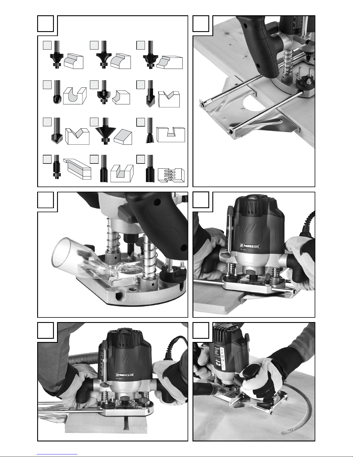
Router set figure D
32
Round and profile cutter 24.7 mm
33
Round and profile cutter 28.6 mm
34
Round and profile cutter 28.6 mm (R-4)
35
Hollow cutter 12 mm
36
Hollow cutter 24.7 mm
37
V-groove cutter 9.5 mm
38
V-groove cutter 16 mm
39
Bevel cutter 32 mm
40
Dovetail cutter 14.3 mm
41
Flush cutter 12.7 mm
42
Slot cutter 6 mm
43
Slot cutter 12 mm
Scope of delivery
1 Router
1 Open-ended spanner with slot
1 Collet 6 mm
1 Collet 8 mm (installed)
1 Extractor
1 Rip fence
1 Copy casing
1 Centring pin
1 Milling set 12 parts (with socket head wrench)
1 Reducer
Page 7

7 GB/CY
Introduction / General safety advice for electrical power tools
1 Socket head wrench
1 Set of operating instructions
Technical Data
Rated power input: 1200 W
Rated voltage: 230 V∼, 50 Hz
Idle speed: n
0
11000–30000 min
-1
Plunge depth: 55 mm
Tool holder: 6/8 mm
Protection class: II /
Noise and vibration data:
Measured sound value determined according to
EN 60745. The A-rated noise levels of the electrical
power tool are typically at:
Sound pressure level: 84.7 dB(A)
Sound power level: 95.7 dB(A)
Uncertainty K: 3 dB
Wear hearing protection!
Evaluated acceleration, typically:
Hand / arm vibration a
h
= 6.437 m / s²
Instability K = 1.5 m / s²
The vibration level specified in
these instructions was measured in accordance with
an EN 60745 standardised measurement process
and can be used to compare equipment. The vibration emission value specified can also serve as a
preliminary assessment of the exposure.
The vibration level will change according to the application of the electrical tool an in some cases may
exceed the value specified in these instructions. Regularly using the electric tool in such a way may
make it easy to underestimate the vibration.
Note: If you wish to make an accurate assessment
of the vibration loads experienced during a particular period of working, you should also take into
account the intervening periods of time when the
device is switched off or is running but is not actually in use. This can result in a much lower vibration
load over the whole of the period of working.
General safety advice for
electrical power tools
Read all the safety advice
and instructions! Failure to observe the safety
advice and instructions may result in electric shock,
fire and / or serious injury.
Keep all the safety advice and instructions
in a safe place for future reference!
The term “electrical tool” used in the safety advice
refers to electrical tools powered by mains electricity (by means of a mains lead) and electrical tools
powered by rechargeable batteries (without a
mains lead).
1. Workplace safety
a) Keep your working area clean and
well lit. Untidy or poorly lit working areas can
lead to accidents.
b) Do not work with the device in poten-
tially explosive environments in which
there are inflammable liquids, gases
or dusts. Electrical power tools create sparks,
which can ignite dusts or fumes.
c) Keep children and other people away
while you are operating the electrical
tool. Distractions can cause you to lose control
of the device.
2. Electrical safety
a)
The mains plug on the device must match
the mains socket. The plug must not be
modified in any way. Do not use an
adapter plug with devices fitted with
a protective earth. Unmodified plugs and
matching sockets reduce the risk of electric shock.
b) Avoid touching earthed surfaces such
as pipes, radiators, ovens and refrigerators with any part of your body.
There is an increased risk of electric shock if
your body is earthed.
Page 8

8 GB/CY
General safety advice for electrical power tools
c) Keep the device away from rain or
moisture. Water entering an electrical device
increases the risk of electric shock.
d) Do not use the mains lead for any pur-
pose for which it was not intended,
e.g.
to carry the device, to hang up the device or to pull the mains plug out of
the mains socket. Keep the mains lead
away from heat, oil, sharp edges or
moving parts of the device. Damaged
or tangled mains leads increase the risk of
electric shock.
e) When working outdoors with an
electrical power tool always use extension cables that are also approved
for use outdoors. The use of an extension
cable suitable for outdoor use reduces the risk
of electric shock.
f) Use a residual current device (RCD)
for protection if operating the electrical power tool in a moist environment
is unavoidable. The use of an RCD reduces
the risk of electric shock.
3. Personal safety
a) Remain alert at all times, watch what
you are doing and always proceed
with caution. Do not use the device if
you are tired or under the influence of
drugs, alcohol or medication. One mo
ment
of carelessness when using the device can lead
to serious injury.
b) Wear personal protective equipment
and always wear safety glasses. The
wearing of personal protective equipment such
as dust masks, non-slip safety shoes, safety helmets or ear protectors, appropriate to the type
of electrical power tool used and work undertaken, reduces the risk of injury.
c) Avoid unintentional operation of the
device. Check that the electrical power
tool is switched off before you connect
it to the mains, pick it up or carry it.
Accidents can happen if you carry the device
with your finger on the ON / OFF switch or with
the device switched on.
d) Remove any setting tools or spanners
before you switch the device on. A tool
or spanner left attached to a rotating part of a
device can lead to injury.
e) Avoid placing your body in an unnat-
ural position. Keep proper footing and
balance at all times. By doing this you will
be in a better position to control the device in
unforeseen circumstances.
f) Wear suitable clothing. Do not wear
loose clothing or jewellery. Keep your
hair, clothing and gloves clear of moving parts. Loose clothing, jewellery or long
hair can become trapped in moving parts.
g) If vacuum dust extraction and collection
devices are fitted do not forget to
check
that they are properly connected and
correctly used. The use of these devices
reduces the hazard presented by dust.
4. Careful handling and use
of electrical power tools
a) Do not overload the device. Always
use an electrical power tool that is
intended for the task you are undertaking. By using the right electrical power
tool for the job you will work more safely and
achieve a better result.
b) Do not use an electrical power tool if
its switch is defective. An electrical power
tool that can no longer be switched on and off
is dangerous and must be repaired.
c) Pull the mains plug from the socket
before you make any adjustments to
the device, change accessories or when
the device is put away. This precaution is
intended to prevent you from unintentionally
starting the device.
d) When not in use always ensure that
electrical power tools are kept out of
reach of children. Do not let anyone use
the device if he or she is not familiar
with it or has not read the instructions
and advice. Electrical power tools are dan-
gerous when they are used by inexperienced
people.
Page 9

9 GB/CY
General safety advice for electrical power tools
e) Look after the device carefully. Check
that moving parts are working properly and move freely. Check for any
parts that are broken or damaged
enough to detrimentally affect the
functioning of the device. Have damaged parts repaired before you use
the device. Many accidents have their origins
in poorly maintained electrical power tools.
f) Keep cutting tools clean and sharp.
Carefully maintained cutting tools with sharp
cutting edges are less likely to jam and are
easier to control.
g) Use the electrical power tool, accesso-
ries, inserted tools etc. in accordance
with these instructions and advice, and
the stipulations drawn up for this particular type of device. In doing this, take
into account the working conditions
and the task in hand. The use of electrical
power tools for purposes other than those intended can lead to dangerous situations.
5. Service
a) Have your device repaired at the ser-
vice centre or by qualified specialist
personnel using original manufacturer
parts only. This will ensure that your device
remains safe to use.
S
afety notices specific to routers
Only hold the power tool by the insu-
lated handle areas as the router may
touch the tool’s mains cable. Contact
with a live wire could cause metal parts of the
device to become live and lead to electric shock.
Fix and secure the work piece to a
stable surface using clamps or other
means. When only securing the work piece
by hand or against your body it will remain
unstable, which could lead to loss of control.
Supplementary Instructions
The permissible rotational speed of the
router tool must be at least as high as
the maximum speed indicated on the
electrical power tool. Parts used at higher
than permissible speeds may be ruined.
The router or other parts must fit pre-
cisely in the collet (shaft diameter 6/8)
of your electric power tool. Cutting tools
which do not fit precisely in the collet of the
electric power tool turn unevenly, vibrate strongly and can lead to a loss of control.
Always switch on the electrical power
tool before placing it against the workpiece. There is also the risk of kickback if the
electric power tool becomes caught in the
work-piece.
Keep your hands away from the cut-
ting area and the router. Keep your
second hand on the additional handle
or on the engine housing. If you hold the
router with both hands, they cannot be injured
by the router.
Never use on metal objects, nails or
screws. The router can become damaged
and this may lead to higher vibrations.
Use suitable detectors in order to look
for hidden supply lines, or consult your
local power authority. Contact with elec-
tric lines can lead to fire and electric shocks.
Damage to a gas line can lead to explosions.
Breaking a water line can cause damages.
Original accessories / tools
U
se only the accessories and attachment
s
detailed in the operating instructions,
or those which are compatible with
the device.
Page 10
10 GB/CY
Start-up / Operation
Start-up
Router set / Applications
Original attachment included in delivery:
To profile:
32
Round and profile cutter, 24.7 mm
33
Round and profile cutter, 28.6 mm
34
Round and profile cutter 28.6 mm (R–4)
35
Hollow cutter, 12 mm
36
Hollow cutter, 24.7 mm
37
V-groove cutter, 9.5 mm
38
V-groove cutter, 16 mm
39
Bevel cutter, 32 mm
To connect:
40
Dovetail cutter, 14.3 mm
41
Flush cutter, 12.7 mm
42
Slot cutter, 6 mm
43
Slot cutter, 12 mm
Note: Provided the router’s ball bearing has loosened, tighten it with the Allen key provided in the
router set.
Using the router tool
Press and hold the spindle lock key 10.
Release the union nut 3 with the open-ended
spanner
27
by turning it anticlockwise.
Release the spindle-lock key 10.
Then use the router tool. This must be inserted
at least 20 mm (shaft length).
Tighten the union nut 3 firmly with the open-
ended spanner
27
.
Attaching the extractor adapter
Put the extractor adapter 21 on the drilling ex-
tractor
18
provided.
Screw together the extractor’s screws 22 and
the under side of the base plate
7
.
Connect a vacuum device approved for the
extraction of sawdust and splinters to the extractor
21
(see Fig. G).
Reducer
Connecting:
Slide the reducer 28 in to the suction adapter 21.
Slide the hose for an approved dust extraction
unit (e.g. a workshop vacuum) onto the reducer
28
.
Removal:
Pull the hose of the vacuum unit off of the re-
ducer
28
.
Pull off the reducer 28.
Changing the collet
Note: All router bits of the router sets have a 8 mm
shaft.
Start with the already installed collet 8 mm
4
.
Change the collet for a router bit with a 6 mm shaft
as described below.
Release the union nut by turning it anticlock-
wise using the open-ended spanner
27
until
the collet 8 mm
4
is removed.
Insert the collet 6 mm 23.
ATTENTION! Tighten the union nut 3 firmly
with the open-ended spanner
27
once the rout-
er bit
17
is inserted. Otherwise the collet might
be damaged.
Fitting the guide fence
Unscrew the both of the sliding bar’s 29
screws with a Philips screw driver.
Secure the sliding bar 29 to the rip fence 24
and tighten the screws.
Operation
Switching on and off
Switching on:
Press and hold the start lockout 20.
Activate the ON / OFF switch 19. Once the
machine has started, release the start lockout
20
.
Page 11
11 GB/CY
Operation
Switching off:
Release the ON / OFF switch 19.
Presetting the speed
Set the desired speed using the speed setting
wheel
1
.
1–2 = low speed
3–4 = middle speed
5–7 = high speed
Set the milling depth
1.
Ensure that the clamping lever 16 is locked down
.
If it is loose turn it anti-clockwise until it is locked.
2. P
lace the device on the work piece to be wo
rked
upon.
3. Turn the step stop
9
until it locks into the lowest
position.
4. Loosen the lock screw
11
.
5. Loosen the clamping lever
16
by turning it
clockwise and pushing the device down until the
route bit touches the surface of the work-piece.
6. Lock the clamping lever in place
16
by turning
it anti-clockwise.
7. Push the depth stop
12
down until it reaches
the lowest position of the step stop
9
. Move
the index indicator
13
to the position “0“ on
the dial milling depth adjustment
14
.
8. Adjust the depth stop
12
to the desired depth,
tighten the lock screw
11
. Afterwards the index
indicator
13
should no longer be adjustable.
9. Loosen the clamping lever
16
and and lead the
device back up.
Readjust the Milling depth
The milling depth can be adjusted with the con-
trol dial
15
.
Loosen the clamping lever 16 by turning it
clockwise and pushing the device down until
the depth stop
12
touches the step stop 9.
Lock the clamping lever in place 16 by turning
it anti-clockwise.
Set the milling depth with the control dial 15.
Loosen the clamping lever 16 by turning it
clockwise and lead the device back up. Check
the milling depth through a further practical test.
Set the milling depth with the
step stop
You can use the step stop 9 with deeper depths in
several steps with less takeoff.
Set the desired milling depth with the lowest
step of the step stop
9
(as described above).
Then set it at higher level for the first attempt.
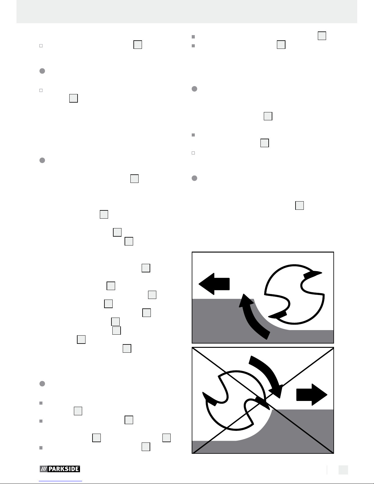
Milling direction
The milling process must always go against the
rotationary direction on the router bit
17
(Counter
rotation).
ATTENTION: When milling in the direction of the
router bit (counter rotation) the device fly out of
your hand.
Page 12

12 GB/CY
Operation / Maintenance and Cleaning / Warranty
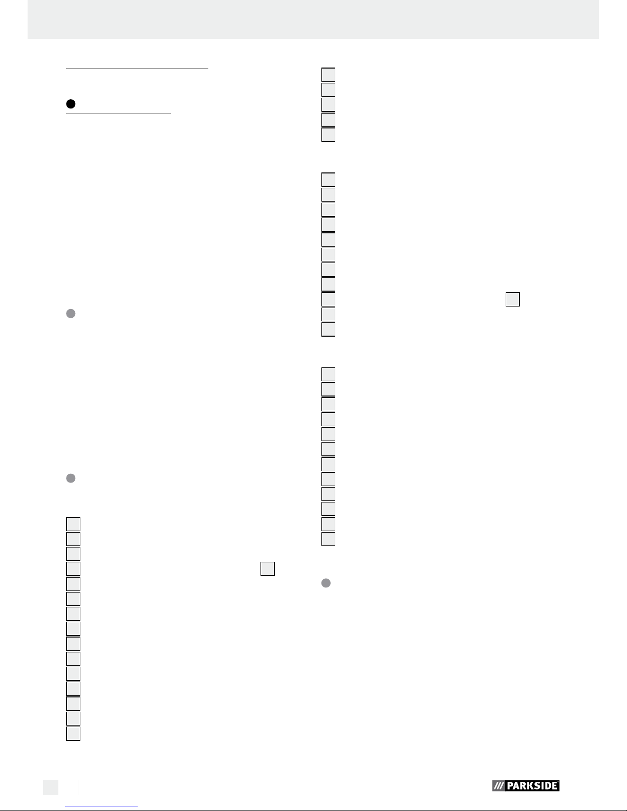
Milling Process
Set the milling depth as previously described.
Place the device on the desired work-piece and
switch it on.
Loosen the clamping lever 16 by turning it clock-
wise and pushing the device down until it touches
the surface of the depth stop
12
on the step
stop
9
.
Lock the device into place by turning the clamp
lever
16
anti-clockwise.
Mill with even speed and even pressure (see fig. I).
Set the copy casing
Set the copy casing 26 from below on the slid-
ing bar
8
.
Secure the copy casing 26 with the two screws
22
of the extractor adapter on the base plate 7.
Ensure that the copy casing
26
is set the right
way round - the thrust ring
25
must be pointing
down (see fig. D).
Milling with the copy casing
Note! The pattern must be at least as high as the
copy casing’s
26
thrust ring 25.
Note! Chose the router bit as small as the inner
diameter of the copy casing.
When using a copy casing
26
the pattern can be
transferred onto the work piece.
Place the router with the copy casing on the
pattern.
Loosen the clamping lever 16 by turning it
clockwise and lower the device until it reaches
predetermined depth.
Lead the device with the protecting copy cas-
ing along the pattern. Apply pressure lightly.
Milling with a rip fence
Push the rip fence 24 along the guide rail 6 of
the base plate
7
and tighten the screws 5.
Put the rip fence 24 on the edge of the work
piece (see fig. F, H).
Milling with a circular compass
(see fig. J)
Put the centring pin 30 in the marked mid point
of the circle.
Turn the rip fence 24 over, i.e.the fence side is
facing upwards.
Screw together the centre pin and the rip fence
with a wing bolt. Lock the centre pin to the s
crews
with the slot of the open-ended spanner
27
.
Maintenance and Cleaning
RISK OF INJURY! Switch the
device off and pull the plug out of the mains socket
before carrying out any work on the device.
Always keep the device clean, dry and free of
oil or grease.
Use a dry cloth to clean the housing.
If the connection cable needs
to be replaced, this repair must be performed
by the manufacturer or a representative to prevent safety hazards.
Warranty
The warranty for this appliance is for 3
years from the date of purchase. The appliance has been manufactured with care
and meticulously examined before delivery. Please retain your receipt as proof
of purchase. In the event of a warranty
claim, please make contact by telephone
with our Service Department. Only in this
way can a post-free despatch for your
goods be assured.
The warranty covers only claims for material and
maufacturing defects, but not for transport damage,
for wearing parts or for damage to fragile compo-
Page 13

13 GB/CY
Warranty / Disposal
nents, e.g. buttons or batteries. This product is for private use only and is not intended for commercial use.
The warranty is void in the case of abusive and improper handling, use of force and internal tampering
not carried out by our authorized service branch. Your
statutory rights are not restricted in any way by this
warranty.
The warranty period will not be extended by repairs
made unter warranty. This applies also to replaced
and repaired parts. Any damage and defects extant
on purchase must be reported immediately after
unpacking the appliance, at the latest, two days after
the purchase date. Repairs made after the expiration
of the warranty period are subject to payment.
GB
Service Great Britain
Tel.: 0871 5000 720
(0,10 GBP/Min.)
e-mail: kompernass@lidl.co.uk
IAN 90981
CY
Service Cyprus
Tel.: 8009 4409
e-mail: kompernass@lidl.com.cy
IAN 90981
Disposal
The packaging is wholly composed of
environmentally-friendly materials that can
be disposed of at a local recycling centre.
Do not dispose of electrical power
tools with the household rubbish!
In
accordance with European Directive 2002 / 96 / EC,
worn out electrical power tools must be collected
separately and taken for environmentally compatible
recycling.
Contact your local refuse disposal authority for more
details of how to dispose of your worn-out devices.
Page 14

14 GB/CY
Declaration of conformity / Manufacturer
Declaration of conformity /
Manufacturer
We, KOMPERNASS HANDELS GMBH, the person
responsible for documents: Mr Semi Uguzlu, BURGSTRASSE 21, 44867 BOCHUM, GERMANY, hereby
declare that this product complies with the following
standards, normative documents and EU directives:
Machinery Directive
(2006 / 42 / EC)
EU Low Voltage Directive
(2006 / 95 / EC)
Electromagnetic Compatibility
(2004 / 108 / EC)
RoHS Directive
(2011 / 65 / EU)
Applicable harmonized standards
EN 60745-1:2009+A11
EN 60745-2-17:2010
EN 55014-1:2006+A1+A2
EN 55014-2:1997+A1+A2
EN 61000-3-2:2006+A1+A2
EN 61000-3-3:2008
Type / Device description:
Router POF 1200 A1
Date of manufacture (DOM): 08–2013
Serial number: IAN 90981
Bochum, 31.08.2013
Semi Uguzlu
- Quality Manager -
We reserve the right to make technical modifications in the course of further development.
Page 15

15 GR/CY
Εισαγωγή
Χρήση σύμφωνα με τις προδιαγραφές ..........................................................................................Σελίδα 16
Εξοπλισμός ......................................................................................................................................Σελίδα 16
Περιεχόμενα παράδοσης ................................................................................................................Σελίδα 16
Τεχνικά χαρακτηριστικά ...................................................................................................................Σελίδα 17
Γενικέ υποδείξει ασφάλεια για ηλεκτρικά εργαλεία
1. Θέση εργασίας-ασφάλεια ...........................................................................................................Σελίδα 17
2. Ηλεκτρική ασφάλεια ....................................................................................................................Σελίδα 18
3. Ασφάλεια ατόμων ........................................................................................................................Σελίδα 18
4. Ασφαλής λειτουργία και χρήση ηλεκτρονικών συσκευών.........................................................Σελίδα 19
5. Σέρβις ..........................................................................................................................................Σελίδα 19
Ειδικές για τη συσκευή υποδείξεις ασφαλείας για το φρεζάρισμα ..............................................Σελίδα 19
Συμπληρωματικές οδηγίες ...............................................................................................................Σελίδα 20
Αυθεντικός πρόσθετος εξοπλισμός / πρόσθετες συσκευές .........................................................Σελίδα 20
Θέση σε λειτουργία
Σετ φρεζαρίσματος / περιοχές εφαρμογής ....................................................................................Σελίδα 20
Τοποθέτηση εργαλείου φρεζαρίσματος .........................................................................................Σελίδα 20
Σύνδεση προσαρμογέα αναρρόφησης .........................................................................................Σελίδα 21
Εξάρτημα συστολής ........................................................................................................................Σελίδα 21
Αντικατάσταση λαβίδας σύσφιξης .................................................................................................Σελίδα 21
Συναρμολόγηση παράλληλου αναστολέα ....................................................................................Σελίδα 21
Χειρισό
Ενεργοποίηση και απενεργοποίηση ...............................................................................................Σελίδα 21
Προεπιλογή αριθμού στροφών ......................................................................................................Σελίδα 21
Ρύθμιση βάθους φρεζαρίσματος ...................................................................................................Σελίδα 22
Επαναρύθμιση του βάθους φρεζαρίσματος .................................................................................Σελίδα 22
Ρύθμιση του βάθους φρεζαρίσματος με αναστολέα βάθους με βαθμίδες .................................Σελίδα 22
Κατεύθυνση φρεζαρίσματος ...........................................................................................................Σελίδα 22
Διαδικασία φρεζαρίσματος ............................................................................................................Σελίδα 23
Τοποθέτηση χιτωνίου αντιγραφής ..................................................................................................Σελίδα 23
Φρεζάρισμα με χιτώνιο αντιγραφής ...............................................................................................Σελίδα 23
Φρεζάρισμα με παράλληλο αναστολέα .........................................................................................Σελίδα 23
Φρεζάρισμα με διαβήτη ..................................................................................................................Σελίδα 23
Συντήρηση και καθαρισό .........................................................................................Σελίδα 23
Εγγύηση ........................................................................................................................................Σελίδα 24
Απόσυρση ...................................................................................................................................Σελίδα 24
ήλωση συόρφωση / Kατασκευαστή .........................................................Σελίδα 25
Πίνακας περιεχομένων
Page 16

16 GR/CY
Eισαγωγή
Καθετη φρεζα POF 1200 A1
Q
Εισαγωγή
Σας συγχαίρουμε για την αγορά της νέας σας
συσκευής. Επιλέξατε ένα προϊόν υψηλών προδιαγραφών. Οι οδηγίες χρήσης είναι μέρος αυτού του
προϊόντος. Περιέχουν σημαντικές πληροφορίες
σχετικά με την ασφάλεια, το χειρισμό και την απόρριψη
.
Πριν τη χρήση του προϊόντος εξοικειωθείτε με όλες
τις οδηγίες χρήσης και ασφαλείας. Χρησιμοποιείτε
το προϊόν μόνο με τον τρόπο που περιγράφεται
και για τον τομέα εφαρμογής που αναφέρεται. Σε
περίπτωση μεταβίβασης του προϊόντος σε τρίτους
παραδώστε μαζί και όλα τα έγγραφα.
Χρήση σύφωνα ε τι
προδιαγραφέ
Η συσκευή προορίζεται σταθερά στερεωμένη να
φρεζάρει αυλακώσεις, ακμές, προφίλ και επιμήκεις
οπές σε ξύλο, πλαστικό και ελαφρά υλικά, καθώς
και να φρεζάρει με αντιγραφή. Η συσκευή δεν προορίζεται για χρήση σε εξωτερικό χώρο. Οποιαδήποτε άλλη χρήση ή τροποποίηση του μηχανήματος
θεωρείται ως αντικανονική και εγκυμονεί σοβαρούς
κινδύνους ατυχημάτων. Αντενδείκνυται η επαγγελματική χρήση.
Εξοπλισό
Μπροστινή όψη Εικόνα A
1
Προεπιλογή αριθμού στροφών
2
Χειρολαβή
3
Παξιμάδι ρακόρ
4
Λαβίδα σύσφιξης 8 mm (προτοποθετημένη σε
παξιμάδι ρακόρ
3
)
5
Βίδα στερέωσης
6
Ράγα οδηγός
7
Πλάκα έδρασης
8
Πλάκα ολίσθησης
9
Αναστολέας βάθους με βαθμίδες
10
Κουμπί ασφάλισης ατράκτου
11
Βίδα ασφάλισης
12
Αναστολέας βάθους
13
Ενδείκτης
14
Κλίμακα ρύθμισης βάθους φρεζαρίσματος
15
Ρυθμιστής στροφών (ρύθμιση ακριβείας βά-
θους φρεζαρίσματος)
Πίσω όψη Εικόνα B
16
Μοχλός σύσφιξης
17
Εργαλείο φρεζαρίσματος
18
Οπές προσαρμογέα αναρρόφησης
19
Διακόπτης ΟΝ / ΟFF
20
Διάταξη ασφάλισης ενεργοποίησης
Πρόσθετο εξοπλισό Εικόνα C
21
Προσαρμογέας αναρρόφησης
22
Βίδα
23
Λαβίδα σύσφιξης 6 mm
24
Παράλληλος αναστολέας
25
Δακτύλιος εδράνου κύλισης
26
Χιτώνιο αντιγραφής
27
Ανοικτό κλειδί με επιμήκη οπή
28
Εξάρτημα μείωσης
29
Ράβδος ολίσθησης με βίδα για τον παράλληλο
αναστολέα
24
30
Άξονας κεντραρίσματος
31
Κλειδί Άλεν
Σετ φρεζαρίσατο Εικόνα D
32
Φρέζα στρογγύλευσης / με σταθερό προφίλ
24,7 mm
33
Φρέζα στρογγύλευσης / με σταθερό προφίλ
28,6 mm
34
Φρέζα στρογγύλευσης / με σταθερό προφίλ
28,6 mm (R–4)
35
Φρέζα κοίλης αυλάκωσης 12 mm
36
Φρέζα κοίλης αυλάκωσης 24,7 mm
37
Φρέζα αυλάκωσης σχήματος V 9,5 mm
38
Φρέζα αυλάκωσης σχήματος 16 mm
39
Φρέζα κοπής απολήξεων οδόντων 32 mm
40
Φρέζα με όδοντες 14,3 mm
41
Επίπεδη φρέζα 12,7 mm
42
Φρέζα αυλακώσεων 6 mm
43
Φρέζα αυλακώσεων 12 mm
Περιεχόενα παράδοση
1 Καθετη φρεζα
1 Ανοικτό κλειδί με επιμήκη κοπή
Page 17

17 GR/CY
1 Λαβίδα σύσφιξης 6 mm
1 Λαβίδα σύσφιξης 8 mm (τοποθετημένη)
1 Προσαρμογέας αναρρόφησης
1 Παράλληλος αναστολέας
1 Χιτώνιο αντιγραφής
1 Άξονας κεντραρίσματος
1 Σετ φρέζας 12 τεμαχίων (με κλειδί Άλεν)
1 Εξάρτημα συστολής
1 Κλειδί Άλεν
1 Οδηγίες χρήσης
Τεχνικά χαρακτηριστικά
Ονομαστική ισχύς: 1200 W
Ονομαστική τάση: 230 V∼, 50 Hz
Αριθμός στροφών ρελαντί:
n0 11000–30000 min
–1
Διαδρομή κάτω μέρους
φρέζας: 55 mm
Υποδοχή εργαλείου: 6 / 8 mm
Κλάση προστασίας: II /
Πληροφορίε θορύβου και κραδασών:
Τιμή μέτρησης για θόρυβο εξακριβωμένη σύμφωνα
με EN 60745. Η αξιολογημένη με Α στάθμη ηχητικ
ής
πίεσης του ηλεκτρικού εργαλείου ανέρχεται τυπικά σε:
Στάθμη ηχητικής πίεσης: 84,7 dB(A)
Στάθμη ηχητικής ισχύος: 95,7 dB(A)
Αβεβαιότητα μέτρησης K: 3 dB
Φοράτε ωτασπίδε!
Αξιολογηένη επιτάχυνση, τυπικά:
Κραδασμοί στο χέρι / βραχίονα a
h
= 6,437 m / s²
Αβεβαιότητα μέτρησης K = 1,5 m / s²
Η αναφερόμενη στις
παρούσες οδηγίες στάθμη δονήσεων μετρήθηκε με
τυποποιημένη μέθοδο μέτρησης σύμφωνα με το
πρότυπο EN 60745 και μπορεί να χρησιμοποιηθεί
για τη σύγκριση της συσκευής. Η δεδομένη τιμή
εκπομπής δονήσεων μπορεί επίσης να χρησιμοποιηθ
εί
σε μια εισαγωγική εκτίμηση της έκθεσης.
Η στάθμη δονήσεων μεταβάλλεται ανάλογα με τη
χρήση του ηλεκτρικού εργαλείου και σε μερικές
περιπτώσεις ενδέχεται να υπερβαίνει την τιμή που
αναφέρεται στις παρούσες οδηγίες. Η επιβάρυνση
δονήσεων ενδέχεται να υποτιμηθεί, σε περίπτωση
που το ηλεκτρικό εργαλείο χρησιμοποιείται τακτικά
με τέτοιο τρόπο.
Υπόδειξη: Για τον ακριβή υπολογισμό της επιβάρυνσης κραδασμών κατά τη διάρκεια ενός ορισμένου χρονικού διαστήματος εργασίας θα πρέπει να
ληφθούν υπόψη και οι χρόνοι κατά τους οποίους
η συσκευή είναι απενεργοποιημένη ή λειτουργεί χωρίς όμως να παράγει πραγματικά έργο. Αυτό μπορεί
να μειώσει σημαντικά την επιβάρυνση κραδασμών για
το συνολικό χρονικό διάστημα εργασίας.
Γενικέ υποδείξει ασφάλεια
για ηλεκτρικά εργαλεία
ιαβάστε όλε τι
υποδείξει ασφάλεια και οδηγίε! Οι πα-
ραβιάσεις κατά την τήρηση των υποδείξεων ασφάλειας και των οδηγιών ενδέχεται να προκαλέσουν
ηλεκτροπληξία, πυρκαγιά ή / και σοβαρούς τραυματισμούς.
ιαφυλαξτε ολε τι υποδειξει ασφαλεια
και τι οδηγιε για ελλοντικη χρηση!
Ο ορος που χρησιμοποιειται στις υποδειξεις ασφαλ
ειας «ηλεκτρονικο εργαλειο» αναφερεται σε ηλεκτρικ
α
εργαλεια που λειτουργουν με το δικτυο (με καλωδιο
δικτυου) και σε αυτa που λειτουργουν με μπαταρια
(χωρις καλωδιο δικτυου).
1. Θέση εργασία-ασφάλεια
α) ιατηρείτε το χώρο εργασία σα κα-
θαρό και καλά φωτισένο. Η ακαταστασία
καθώς και ο ελλιπής φωτισμός του χώρου εργασίας μπορεί να οδηγήσει σε ατυχήματα.
β) Μην εργάζεστε ε τη συσκευή σε περι-
βάλλον όπου υφίστα ται κίνδυνο
έκρηξη, στο οποίο υπάρχουν εύφλεκτα υγρά, αέρια ή σκόνη. Τα ηλεκτρονικά
εργαλεία παράγουν σπίθες, οι οποίες μπορεί
να αναφλέξουν τη σκόνη ή τους ατμούς.
γ) Κρατήστε τα παιδιά και άλλα άτοα
ακριά από το ηλεκτρο νικό εργαλείο
κατά τη διάρκεια χρήση του. Σε περί-
Eισαγωγή / Γενικές υποδείξεις ασφάλειας για ηλεκτρικά εργαλεία
Page 18

18 GR/CY
Γενικές υποδείξεις ασφάλειας για ηλεκτρικά εργαλεία
πτωση μη τήρησης ίσως χάσετε τον έλεγχο της
συσκευής.
2. Ηλεκτρική ασφάλεια
α) Το βύσα σύνδεση συσκευή θα πρέ-
πει να ταιριάζει στην πρίζα. Απαγορεύεται η τροποποίηση ε οποιοδήποτε
τρόπο του βύσατο. Απαγορεύεται η
χρήση βύσατο προσαρογέα αζί
ε συσκευέ ε προστατευτική γείωση.
Το ανέπαφο βύσμα και η κατάλληλη πρίζα μειώνουν τον κίνδυνο πρόκλησης ηλεκτροπληξίας.
β) Αποφύγετε τη σωατική επαφή ε
γειωένε επιφάνειε, όπω σωλήνε,
θεραντικά σώατα, εστίε και ψυγεία.
Υφίσταται υψηλός κίνδυνος ηλεκτροπληξίας
όταν το σώμα σας γειωθεί.
γ) Κρατήστε τη συσκευή ακριά από τη
βροχή και την υγρασία. Η εισχώρηση νε
ρού
μέσα σε μία ηλεκτρονική συσκευή αυξάνει τον
κίνδυνο ηλεκτροπληξίας.
δ) Μην χρησιοποιείτε το καλώδιο για
άλλο λόγο, για να εταφέρετε τη συσκευή, για να την αναρτήσετε ή για να
τραβήξετε το βύσα από την πρίζα.
Κρατήστε το καλώδιο ακριά από θερότητα, λάδι, αιχηρέ ακέ ή κινούενα εξαρτήατα συσκευή. Κατεστραμμένο
ή τυλιγμένο καλώδιο αυξάνει τον κίνδυνο πρόκλησης ηλεκτροπληξίας.
ε) Για χρήση ηλεκτρονική συσκευή σε
εξωτερικού χώρου, χρησιοποιήστε
όνο καλώδιο επέκταση που είναι
κατάλληλο για εξωτερική χρήση. Η
χρήση ενός καλωδίου κατάλληλο για εξωτερική
χρήση μειώνει τον κίνδυνο ηλεκτροπληξίας.
ζ) Σε περίπτωση που είναι αναπόφευκτη
η λειτουργία του ηλεκτρικού εργαλείου
σε υγρό περιβάλλον, χρησιοποιείτε
προστατευτικό διακόπτη συνολικού
ρεύατο προ το σφάλα. Η χρήση
προστατευτικού διακόπτη συνολικού ρεύματος
προς το σφάλμα μειώνει τον κίνδυνο ηλεκτροπληξίας.
3. Ασφάλεια ατόων
α) Επιδείξτε εγάλη προσοχή, έχετε πάντο-
τε επίγνωση των πράξεών σα και δείξτε ιδιαίτερη συναίνεση στην εργασία
που πραγατοποιείτε ε το ηλεκτρονικό εργαλείο. Μην χρησιοποιείτε τη
συσκευή όταν δεν
είσαστε συγκεντρω-
ένοι ή όταν
νοιώθετε κούραση ή ενώ
βρίσκεστε υπό
την επήρεια ναρκωτικών,
αλκοόλ ή φαράκων. Ακόμα και μόλις μία
στιγμή
αφηρημάδας κατά τη χρήση της συσκευής
μπορεί να οδηγήσει σε σοβαρούς τραυματι
σμούς.
β) Φοράτε προσωπικό προστατευτικό εξο-
πλισό και πάντα προστατευτικά γυαλιά. Ο προσωπικός προστατευτικός εξοπλισμός
όπως είναι αναπνευστική μάσκα, προστατευτικά
παπούτσια που δεν γλιστράνε, προστατευτικό
κράνος ή ωτοασπίδες, ανάλογα με το είδος και
την εφαρμογή του μειώνουν τον κίνδυνο πρόκλησης τραυματισμών.
γ) Αποφεύγετε την αθέλητη θέση σε λει-
τουργία. Βεβαιωθείτε ότι το ηλεκτρικό
εργαλείο είναι απενεργοποιηένο προτού το συνδέσετε στην ηλεκτρική τροφοδοσία ή το πάρετε και το εταφέρετε.
Εάν κατά τη μεταφορά της συσκευής έχετε το
δάκτυλό σας στο διακόπτη ΕΝΤΟΣ / ΕΚΤΟΣ ή
η συσκευή είναι ενεργοπ οιημένη, ενδέχεται να
προκληθούν ατυχήματα.
δ) Αποακρύνετε τα εργαλεία ρύθιση ή
τα κλειδιά προτού ενεργοποιήσετε τη
συσκευή. Ενα εργαλείο ή ένα κλειδί που βρί-
σκεται πάνω σε ένα περιστρεφόμενο εξάρτημα
συσκευής μπορεί να προκαλέσει τραυματισμούς.
ε) Αποφεύγετε αντικανονική στάση του
σώατό σα. Φροντίζετε ώστε να
υπάρχει πάντα σταθερή θέση και διατηρείτε ανά πάση στιγή την ισορροπία
σα. Ετσι μπορείτε να ελέγχετε καλύτερα τη συ-
σκευή και ιδιαίτερα σε απρόσμενες καταστάσεις.
ζ) Φοράτε κατάλληλο ρουχισό. Μην
φοράτε φαρδιά ρούχα και κοσήατα.
Κρατήστε τα αλλιά, το ρουχισό και
τα γάντια ακριά από τα κινούενα
εξαρτήατα. Ο φαρδύς ρουχισμός που δεν
έχει στενή εφαρμογή, τα κοσμήματα ή τα μαλλιά
μπορεί να πιαστούν από τα κινούμενα εξαρτήματα.
Page 19

19 GR/CY
Γενικές υποδείξεις ασφάλειας για ηλεκτρικά εργαλεία
η) Κατά τη συναρολόγηση διατάξεων
αναρρόφηση και συλλογή, φροντί
στε ώστε αυτέ να έχουν συνδεθεί και
να χρησιοποιούνται σωστά. Η χρήση
τέτοιου είδους διατάξεων μειώνει τον κίνδυνο
από τη σκόνη.
4. Ασφαλή λειτουργία και χρήση
ηλεκτρονικών συσκευών
α) Μην υπερφορτώνετε τη συσκευή. Χρη-
σιοποιήστε το ηλεκτρονικό εργαλείο
που είναι κατάλληλο για την εργασία
σα. Με το κατάλληλο ηλεκτρονικό εργαλείο
μπορείτε να εργαστείτε καλύτερα και με μεγαλύτερη ασφάλεια εντός του καθορισμένου τομέα
απόδοσης.
β) Μην χρησιοποιείτε ηλεκτρονικό
εργαλείο, του οποίου ο διακόπτη
είναι ελαττωατικό. Ενα ηλεκτρονικό
εργαλείο που δεν μπορεί να ενεργοποιηθεί ή να
απενεργοποιηθεί είναι επικίνδυνο και θα πρέπει
να επιδιορθωθεί.
γ)
Πριν προβείτε σε ρυθίσει τη ηχανή
,
σε αντικατάσταση εξαρτηάτων ή σε
απόθεση τη ηχανή, αποσυνδέετε το
βύσα από την ηλεκτρική πρίζα. Αυτά
τα προστατευτικά μέτρα μειώνουν τον κίνδυνο
αθέμιτης εκκίνησης της συσκευής.
δ) Φυλάξτε τα ηλεκτρονικά εργαλεία που
δεν χρησιοποιείτε ακριά από παιδιά.
Μην επιτρέπετε τη χρήση τη συσκευή
σε άτοα, τα οποία δεν είναι έπιστα ή
τα οποία δεν έχουν διαβάσει τι οδηγίε.
Τα ηλεκτρονικά εργαλεία είναι επικίνδυνα όταν
χρησιμοποιούνται από άπειρα άτομα.
ε) Φροντίστε τη συσκευή ε προσοχή.
Ελέγχετε αν τα κινούενα εξαρτήατα
λειτουργούν άψογα και δεν πλοκάρουν, αν υπάρχουν σπασένα ή κατεστραένα εξαρτήατα έτσι ώστε να
επηρεάζεται αρνητικά η λειτουργία
τη
συσκευή. Αναθέστε την επιδιό ρθωση
των ελαττωατικών εξαρτη άτων πριν
από τη χρήση στη συσ κευή. Πολλά
ατυχήματα οφείλονται σε ηλεκτρονικές συσκευές
που δεν έχουν συντηρηθεί σωστά.
ζ) ιατηρήστε τα εργαλεία κοπή αιχηρά
και καθαρά. Τα προσεγμένα εργαλεία κοπής
μπλοκάρουν λιγότερο και κόβουν πιο εύκολα.
η) Χρησιοποιήστε το ηλεκτρονικό εργα-
λείο, το εξάρτηα, τα εργαλεία εφαρογή κ.τ.λ. σύφωνα ε τι οδηγίε
του και ε τον τρόπο που περιγράφεται για αυτό τον ειδικό τύπο συσκευή.
Λάβετε υπόψη σα τι συνθήκε εργασία και τι δραστηριότητε που πρέπει
να πραγατοποιηθούν. Η χρήση ηλεκτρο-
νικών εργαλείων για εφαρμογή άλλη από αυτή
που προδιαγράφεται μπορεί να οδηγήσει σε
επικίνδυνες καταστάσεις.
5. Σέρβι
α) Αναθέστε την επιδιόρθωση τη συσκευ-
ή σα σε υπηρεσία εξυπηρέτηση πελατών ή σε εξειδικευένο ηλεκτρολόγο
και χρησιοποιήστε όνο αυθεντικά
ανταλλακτικά. Με τον τρόπο αυτό μπορεί
να
διασφαλιστεί το γεγονός ότι διατηρείται το επίπεδο ασφάλειας της συσκευής.
Ειδικέ για τη συσκευή
υποδείξει ασφαλεία για
το φρεζάρισα
Πιάνετε το ηλεκτρικό εργαλείο όνο
από τι ονωένε επιφάνειε λαβή,
καθώ η ηχανή φρεζαρίσατο πορεί να ακουπήσει το καλώδιο δικτύου
τη. Η επαφή με έναν αγωγό που φέρει τάση
μπορεί να θέσει υπό τάση τα μεταλλικά εξαρτήματα της συσκευής και να οδηγήσει σε ηλεκτροπληξία.
Στερεώστε και ασφαλίστε το τεάχιο
εργασία έσω πίεση ή κατά άλλο τρόπο σε ένα σταθερό υπόστρωα. Αν κρατάτε
το τεμάχιο εργασίας μόνο με το χέρι ή κόντρα
στο σώμα, παραμένει ασταθές, κάτι που μπορεί
να οδηγήσει σε απώλεια ελέγχου.
Page 20

20 GR/CY
Συπληρωατικέ οδηγίε
Ο επιτρεπτό αριθό στροφών των
εργαλείων φρεζαρίσατο πρέπει να
είναι τουλάχιστον ίσο ε το έγιστο
α
ριθό στροφών που αναγράφεται στ
ο
ηλεκτρικό εργαλείο. Ο πρόσθετος εξοπλι-
σμός, που περιστρέφεται γρηγορότερα από το
επιτρεπόμενο, μπορεί να καταστραφεί.
Η ηχανή φρεζαρίσατο ή ο άλλο
πρόσθετο εξοπλισό πρέπει να ταιριάζουν ακριβώ στη λαβίδα σύσφιξη
(διάετρο κορού 6 / 8 mm) του ηλεκτρικού εργαλείου σα. Τα εργαλεία φρε-
ζαρίσματος, τα οποία δεν ταιριάζουν ακριβώς
στη λαβίδα σύσφιξης του ηλεκτρικού εργαλείου
σας, περιστρέφονται ανομοιόμορφα, δονούνται
πολύ και μπορούν να οδηγήσουν σε απώλεια
του ελέγχου.
Οδηγείτε το ηλεκτρικό εργαλείο στο τε-
άχιο εργασία όνο όταν είναι ενεργοποιηένο. Διαφορετικά υφίσταται κίνδυνος
ανάκρουσης, όταν το εργαλείο τοποθέτησης
αγκιστρώνεται στο τεμάχιο εργασίας.
Μην τοποθετείτε τα χέρια σα στην πε-
ριοχή φρεζαρίσατο και στη ηχανή
φρεζαρίσατο. Με το δεύτερό σα χέρι
κρατάτε την πρόσθετη λαβή ή το περίβληα οτέρ. Όταν κρατάτε τη μηχανή φρε-
ζαρίσματος και με τα δυο σας χέρια, τα χέρια
σας δεν είναι δυνατό να τραυματιστούν από τη
μηχανή φρεζαρίσματος.
Ποτέ ην φρεζάρετε εταλλικά αντικείε-
να, καρφιά ή βίδε. Η μηχανή φρεζαρίσματος
μπορεί να υποστεί βλάβη και να προκληθού
ν
πολύ έντονοι κραδασμοί.
Χρησιοποιήστε κατάλληλε συσκευέ
αναζήτηση, για να εντοπίσετε κρυφά
καλώδια τροφοδοσία ή συβουλευτείτε την τοπική εταιρεία ηλεκτροδότηση.
Η επαφή με ηλεκτρικά καλώδια μπορεί να οδηγήσει σε πυρκαγιά ή ηλεκτροπληξία. Η πρόκληση βλάβης σε έναν αγωγό αερίου μπορεί να
οδηγήσει σε έκρηξη. Η εισροή σε έναν αγωγό
νερού μπορεί να προκαλέσει υλικές ζημίες.
Αυθεντικό πρόσθετο εξοπλι-
σό / πρόσθετε συσκευέ
Χρησιοποιείτε όνο πρόσθετο εξο-
πλισό και συσκευέ, οι οποίε αναφέρονται στο εγχειρίδιο λειτουργία ή η
υποδοχή των οποίων είναι συβατή ε
τη συσκευή.
Θέση σε λειτουργία
Σετ φρεζαρίσατο / περιοχέ
εφαρογή
Οι αυθεντικέ πρόσθετε συσκευέ περιλαβάνονται στα παραδοτέα:
Για την κοπή προφίλ:
32
Φρέζα στρογγύλευσης / με σταθερό προφίλ,
24,7 mm
33
Φρέζα στρογγύλευσης / με σταθερό προφίλ,
28,6 mm
34
Φρέζα στρογγύλευσης / με σταθερό προφίλ,
28,6 mm (R–4)
35
Φρέζα κοίλης αυλάκωσης, 12 mm
36
Φρέζα κοίλης αυλάκωσης, 24,7 mm
37
Φρέζα αυλάκωσης σχήματος V, 9,5 mm
38
Φρέζα αυλάκωσης σχήματος V, 16 mm
39
Φρέζα κοπής απολήξεων οδόντων, 32 mm
Για τη σύνδεση:
40
Φρέζα με όδοντες, 14,3 mm
41
Επίπεδη φρέζα, 12,7 mm
42
Φρέζα αυλακώσεων, 6 mm
43
Φρέζα αυλακώσεων, 12 mm
Υπόδειξη: Εάν ο ένσφαιρος τριβέας μιας μηχαν
ής
φρεζαρίσματος έχει χαλαρώσει, σφίξτε τον με το
κλειδί Άλεν που περιλαμβάνεται στο σετ μηχανής
φρεζαρίσματος.
Τοποθέτηση εργαλείου
φρεζαρίσατο
Πατήστε το κουμπί ασφάλισης ατράκτου 10 και
κρατήστε το πατημένο.
Γενικές υποδείξεις ασφάλειας για ηλεκτρικά εργαλεία / Θέση σε λειτουργία
Page 21

21 GR/CY
Χαλαρώστε με το ανοικτό κλειδί 27 το παξιμά-
δι ρακόρ
3
περιστρέφοντας αριστερόστροφα.
Αφήστε τώρα το κουμπί ασφάλισης ατράκτου 10.
Τοποθετήστε το εργαλείο φρεζαρίσματος. Πρέπει
να ωθηθεί τουλάχιστον 20 mm (μήκος κορμού).
Σφίξτε το παξιμάδι ρακόρ 3 με το ανοικτό
κλειδί
27
.
Σύνδεση προσαρογέα
αναρρόφηση
Τοποθετήστε τον προσαρμογέα αναρρόφησης 21
στις προκαθορισμένες οπές για τον προσαρμογέα αναρρόφησης
18
.
Τώρα βιδώστε τις βίδες του προσαρμογέα
αναρρόφησης
22
από την κάτω πλευρά της
πλάκας έδρασης
7
.
Συνδέστε τον επιτρεπτό προσαρμογέα αναρρό-
φησης σκόνης και ρινισμάτων στον προσαρμογ
έα
αναρρόφησης
21
(βλέπε εικ. G).
Εξάρτηα συστολή
Σύνδεση:
Ωθήστε το εξάρτημα συστολής 28 στον προ-
σαρμογέα αναρρόφησης
21
.
Ωθήστε τον εύκαμπτο αγωγό μιας επιτρεπτής
διάταξης αναρρόφησης σκόνης (π.χ. μιας διάταξης αναρρόφησης εργοστασίου) στο εξάρτημα συστολής
28
.
Αποάκρυνση:
Αφαιρέστε τον εύκαμπτο αγωγό της διάταξης
αναρρόφησης σκόνης από το εξάρτημα συστολής
28
.
Αφαιρέστε το εξάρτημα συστολής 28.
Αντικατάσταση λαβίδα
σύσφιξη
Υπόδειξη: Όλες οι μηχανές φρεζαρίσματος του
σετ φρεζαρίσματος που περιλαμβάνεται στα παραδοτέα παρέχονται με κορμό 8 mm.
Για το σκοπό αυτό χρησιμοποιήστε ήδη προτοποθετημένη λαβίδα σύσφιξης 8 mm
4
. Για τις μηχανές
φρεζαρίσματος με κορμό 6 mm αντικαταστήστε τη
λαβίδα σύσφιξης, όπως περιγράφεται παρακάτω.
Με το ανοικτό κλειδί 27 χαλαρώστε το παξιμά-
δι ρακόρ αριστερόστροφα, έως ότου η λαβίδα
σύσφιξης 8 mm
4
αφαιρεθεί.
Τοποθετήστε λαβίδα σύσφιξης 6 mm 23.
ΠΡΟΣΟΧΗ! Μόνο τότε σφίξτε το παξιμάδι
ρακόρ
3
με ανοικτό κλειδί 27, όταν τοποθετη-
θεί εργαλείο φρεζαρίσματος
17
. Διαφορετικά
η λαβίδα σύσφιξης μπορεί να υποστεί βλάβη.
Συναρολόγηση παράλληλου
αναστολέα
Ξεβιδώστε και τις δύο βίδες των ράβδων ολί-
σθησης
29
με σταυροκατσάβιδο.
Στερεώστε τις ράβδους ολίσθησης 29 στον
παράλληλο αναστολέα
24
και για το σκοπό
αυτό σφίξτε τις βίδες.
Χειρισό
Ενεργοποίηση και
απενεργοποίηση
Ενεργοποίηση:
Πατήστε τη διάταξη ασφάλισης ενεργοποίησης
20
και κρατήστε την πατημένη.
Πατήστε το διακόπτη ΟΝ/ OFF 19. Μόλις το
μηχάνημα ξεκινήσει να λειτουργεί, μπορείτε να
απελευθερώσετε και πάλι τη διάταξη ασφάλισης
ενεργοποίησης
20
.
Απενεργοποίηση:
Αφήστε ελεύθερο το διακόπτη ON / OFF 19.
Προεπιλογή αριθού στροφών
Ρυθμίστε τον απαιτούμενο αριθμό στροφών με
τον τροχό ρύθμισης προεπιλογής αριθμού
στροφών
1
.
1–2 = χαμηλός αριθμός στροφών
3–4 = μέσος αριθμός τροχών
5–7 = υψηλός αριθμός στροφών
Θέση σε λειτουργία / Χειρισμός
Page 22

22 GR/CY
Ρύθιση βάθου φρεζαρίσατο
1. Βεβαιωθείτε ότι ο μοχλός σύσφιξης 16 είναι
ασφαλισμένος. Εάν χαλαρώσει, στρέψτε τον
αριστερόστροφα, μέχρι να ασφαλίσει.
2. Θέστε τη συσκευή στο προς επεξεργασία τεμάχιο εργασίας.
3. Στρέψτε τον αναστολέα βάθους
9
, μέχρι να
ασφαλίσει στην κατώτατη θέση.
4. Χαλαρώστε τη βίδα ασφάλισης
11
.
5. Χαλαρώστε το μοχλό σύσφιξης
16
περιστρέφοντας δεξιόστροφα και πιέστε τη συσκευή προς
τα κάτω, μέχρι η μηχανή φρεζαρίσματος να αγγίξει την επάνω επιφάνεια του τεμαχίου εργασίας.
6. Ασφαλίστε το μοχλό σύσφιξης
16
περιστρέ-
φοντας αριστερόστροφα.
7. Ωθήστε τον αναστολέα βάθους
12
προς τα
κάτω, μέχρι να τοποθετηθεί στην κατώτατη θέση
του αναστολέα βάθους με βαθμίδες
9
. Ωθή-
στε τον ενδείκτη
13
στη θέση „0“ της κλίμακας
ρύθμισης βάθους φρεζαρίσματος
14
.
8. Ρυθμίστε τον αναστολέα βάθους με βαθμίδες
12
στο επιθυμητό βάθος φρεζαρίσματος, σφίξτε τη
βίδα ασφάλισης 11. Στη συνέχεια ο ενδείκτης 13
δεν πρέπει να μετακινηθεί πλέον.
9. Τώρα χαλαρώστε το μοχλό σύσφιξης
16
και
επαναφέρετε τη συσκευή προς τα επάνω.
Επαναρύθιση του βάθου
φρεζαρίσατο
Το βάθος φρεζαρίσματος μπορεί να επανα-
ρυθμιστεί μέσω του ρυθμιστή περιστροφής
15
.
Χαλαρώστε το μοχλό σύσφιξης 16 περιστρέ-
φοντας δεξιόστροφα και πατήστε τη συσκευή
προς τα κάτω, μέχρι ο αναστολέας βάθους
12
να εφαρμόσει στον αναστολέα βάθους με βαθμίδες
9
.
Ασφαλίστε το μοχλό σύσφιξης 16 περιστρέ-
φοντας αριστερόστροφα.
Ρυθμίστε το βάθος φρεζαρίσματος με ρυθμιστή
περιστροφής
15
.
Χαλαρώστε το μοχλό σύσφιξης 16 περιστρέφο-
ντας δεξιόστροφα και επαναφέρετε τη συσκευή
προς τα επάνω. Ελέγξτε το βάθος φρεζαρίσματος με μια ακόμη πρακτική προσπάθεια.
Ρύθιση του βάθου φρεζαρί-
σατο ε αναστολέα βάθου
ε βαθίδε
Εάν τα βάθη φρεζαρίσματος είναι μεγαλύτερα χρησιμοποιήστε τον αναστολέα βάθους με βαθμίδες
9
σε περισσότερες βαθμίδες με χαμηλότερη απομάκρυνση ρινισμάτων.
Ρυθμίστε το επιθυμητό βάθος φρεζαρίσματος με
την κατώτατη βαθμίδα του αναστολέα βάθους
με βαθμίδες 9 (όπως περιγράφεται παραπάνω).
Στη συνέχεια ρυθμίστε τις υψηλότερες βαθμίδες
για τα πρώτα βήματα επεξεργασίας.
Κατεύθυνση φρεζαρίσατο
Η διαδικασία φρεζαρίσματος πρέπει να πραγματοποιείται πάντα με κατεύθυνση αντίθετη προς την
κατεύθυνση περιστροφής της μηχανής φρεζαρίσματος
17
(αντίστροφή κίνηση).
ΠΡΟΣΟΧΗ: Κατά το φρεζάρισμα με κατεύθυνση
περιστροφής (σταθερή ταχύτητα) το ηλεκτρικό εργαλείο μπορεί να φύγει από το χέρι σας.
Χειρισμός
Page 23

23 GR/CY
ιαδικασία φρεζαρίσατο
Ρυθμίστε το βάθος κοπής, όπως περιγράφεται παραπάνω.
Ρυθμίστε τη συσκευή στο προς επεξεργασία
τεμάχιο εργασίας και ενεργοποιήστε τη.
Χαλαρώστε το μοχλό σύσφιξης 16 περιστρέ-
φοντας δεξιόστροφα τη συσκευή μέχρι να εφαρμόσει ο αναστολέας βάθους
12
στον αναστολέα
βάθους με βαθμίδες
9
προς τα κάτω.
Ασφαλίστε τη συσκευή περιστρέφοντας το μο-
χλό σύσφιξης
16
αριστερόστροφα.
Εκτελέστε τη διαδικασία φρεζαρίσματος με ίση
ταχύτητα και ίση πίεση επαφής (βλέπε εικ. I).
Τ
οποθέτηση χιτωνίου αντιγραφή
Τ
οποθετήστε το χιτώνιο αντιγραφής 26 από κά
τω
στην πλάκα ολίσθησης
8
.
Στερεώστε το χιτώνιο αντιγραφής 26 με τις δύο
βίδες
22
του προσαρμογέα αναρρόφησης στην
πλάκα έδρασης
7
. Προσέξτε, ώστε να τοπο-
θετήσετε σωστά το χιτώνιο αντιγραφής
26
– ο
δακτύλιος εδράνου κύλισης
25
πρέπει να δεί-
χνει προς τα κάτω (βλέπε εικ. D).
Φρεζάρισα ε χιτώνιο
αντιγραφή
Υπόδειξη! Το ύψος της καλίμπρας πρέπει να είναι
τουλάχιστον ίσο με το ύψος του δακτυλίου εδράνου
κύλισης
25
του χιτωνίου αντιγραφής 26.
Υπόδειξη! Επιλέξτε μικρότερη μηχανή φρεζαρίσματος από την εσωτερική διάμετρο των χιτωνίων
αντιγραφής.
Με τη χρήση ενός χιτωνίου αντιγραφής
26
οι
καλίμπρες μπορούν να μεταφερθούν στο τεμάχιο
εργασίας.
Τοποθετήστε την επάνω φρέζα με το χιτώνιο
αντιγραφής στην καλίμπρα.
Χαλαρώστε το μοχλό σύσφιξης 16 περιστρέφο-
ντας δεξιόστροφα και κατεβάζοντας τη συσκευή
προς τα κάτω, μέχρι να επιτευχθεί το προηγουμένως το ρυθμισμένο βάθος φρεζαρίσματος.
Τώρα οδηγήστε τη συσκευή με το προεξέχον
χιτώνιο αντιγραφής κατά μήκος της καλίμπρας.
Κατά τη διαδικασία αυτή εργαστείτε με ήπια πίεσ
η.
Φρεζάρισα ε παράλληλο
αναστολέα
Ωθήστε τον παράλληλο αναστολέα 24 στις
ράγες οδήγησης
6
της πλάκας έδρασης 7
και σφίξτε τις βίδες
5
.
Αποθέστε τον παράλληλο αναστολέα 24 στην
ακμή του τεμαχίου εργασίας (βλέπε εικ. F, H).
Φρεζάρισα ε διαβήτη
(βλέπε εικ. J)
Τρυπήστε τον άξονα κεντραρίσματος 30 στο
επισημασμένο κέντρο ενός κύκλου.
Περιστρέψτε τον παράλληλο αναστολέα 24,
δηλαδή η ακμή του αναστολέα να δείχνει προς
τα επάνω.
Βιδώστε με τη βοήθεια της πεταλούδας τον άξο-
να κεντραρίσματος με παράλληλο αναστολέα.
Κρατήστε κόντρα για τη σύσφιξη του άξονα
κεντραρίσματος με την επιμήκη οπή του ανοικτού κλειδιού
27
.
Συντήρηση και καθαρισό
ΚΙΝΥΝΟΣ ΤΡΑΥ-
ΜΑΤΙΣΜΟΥ! Αποσυνδέστε το βύσμα δικτύου από
την πρίζα πριν από όλες τις εργασίες στη συσκευή.
Η συσκευή θα πρέπει να είναι πάντοτε καθαρή,
στεγνή και χωρίς λάδια ή γράσα λίπανσης.
Χρησιμοποιήστε για τον καθαρισμό του περι-
βλήματος ένα στεγνό πανί.
Όταν είναι απαραίτητη
η αντικατάσταση της σύνδεσης παροχής, τότε
αυτή πρέπει εκτελείται από τον κατασκευαστή ή
τον αντιπρόσωπο του, για να αποφεύγονται
κίνδυνοι ασφάλειας.
Χειρισμός / Συντήρηση και καθαρισμός
Page 24

24 GR/CY
Q
Εγγύηση
Έχετε για αυτή τη συσκευή 3 χρόνια εγγύηση από την ηεροηνία αγορά. Η συσκευή
κατασκευάστηκε και ελέγχθηκε προσεκτικά πριν από την αποστολή. Παρακαλούε
φυλάξτε την απόδειξη ταείου ω απόδει
ξη
για την αγορά. Παρακαλούε επικοινωνήστε τηλεφωνικά ε την υπηρεσία σέρβι σε
περίπτωση εγγύηση. Μόνο έτσι πορεί
να εξασφαλιστεί ια δωρεάν αποστολή
του επορεύατό σα.
Η απόδοση εγγύησης ισχύει μόνο για σφάλματα
υλικού ή κατασκευής, όχι όμως για ζημιές από τη
μεταφορά, για εξαρτήματα φθοράς ή για βλάβες
σε εύθραυστα εξαρτήματα, π.χ. διακόπτες ή συσσωρευτές. Το προϊόν προορίζεται μόνο για την
ιδιωτική και όχι για την επαγγελματική χρήση.
Σε περίπτωση κακής μεταχείρισης και ακατάλληλης
χρήσης, σε χρήση βίας και σε παρεμβάσεις οι οποίες δεν διεξήχθησαν από το εξουσιοδοτημένο μας
τμήμα σέρβις, η εγγύηση παύει να ισχύει. Τα νομικά
σας δικαιώματα δεν περιορίζονται μέσω αυτής της
εγγύησης.
Ο χρόνος εγγύησης δεν επεκτείνεται μέσω της απόδοσης εγγύησης. Αυτό ισχύει και για εξαρτήματα
τα οποία έχουν αντικατασταθεί ή επισκευαστεί.
Ενδεχόμενες ήδη υπάρχουσες κατά την αγορά, ζημιές και ελλείψεις πρέπει να αναφέρονται αμέσως
μετά την αποσυσκευασία, το αργότερο όμως δύο
ημέρες μετά την ημερομηνία αγοράς. Επισκευές που
εμφανίζονται μετά τη λήξη του χρόνου εγγύησης
χρεώνονται.
GR
Σέρβι Ελλάδα
Tel.: 801 5000 019
(0,03 EUR/Min.)
e-mail: kompernass@lidl.gr
IAN 90981
CY
Σέρβι Κύπρο
Tel.: 8009 4409
e-mail: kompernass@lidl.com.cy
IAN 90981
Q
Απόσυρση
Η συσκευασία αποτελείται αποκλειστικά
από υλικά που σέβονται το περιβάλλον.
Αποσύρετέ τη με τη βοήθεια των κατά
τόπους υπηρεσιών ανακύκλωσης.
Απαγορεύεται η απόσυρση
ηλεκτρονικών εργαλείων αζί
ε τα οικιακά απορρίατα!
Σύμφωνα με την Ευρωπαϊκή Οδηγία 2002 / 96 / EC
σχετικά με τις ηλεκτρονικές συσκευές και τις παλιές
ηλεκτρονικές συσκευές και την αναφορά στο εθνικό δίκαιο θα πρέπει οι χρησιμοποιημένες ηλεκτρονικές συσκευές να συλλέγονται σε ξεχωριστό χώρο
και να ανακυκλώνονται οικολογικά.
Δυνατότητες απόσυρσης των χρησιμοποιημένων
συσκευών θα πληροφορηθείτε από τη διαχείριση
κοινότητας ή πόλης σας.
Εγγύηση / Απόσυρση
Page 25

25 GR/CY
Q
ήλωση συόρφωση /
Kατασκευαστή
Εμείς, η εταιρία KOMPERNASS HANDELS GMBH,
υπεύθυνος εγγράφων: Κύριος Semi Uguzlu, BURGSTRASSE 21, 44867 BOCHUM, GERMANY, δηλώνουμε με το παρόν ότι το προϊόν αυτό συμφωνεί
με τα ακόλουθα πρότυπα, κανονιστικά έγγραφα
και οδηγίες ΕΚ:
Οδηγία ηχανηάτων
(2006 / 42 / EC)
Οδηγία περί χαηλή τάση ΕΚ
(2006 / 95 / ΕC)
Ηλεκτροαγνητική συβατότητα
(2004 / 108 / ΕC)
RoHS Οδηγία
(2011 / 65 / EU)
Εφαροσθέντα εναρονισένα πρότυπα
EN 60745-1:2009+A11
EN 60745-2-17:2010
EN 55014-1:2006+A1+A2
EN 55014-2:1997+A1+A2
EN 61000-3-2:2006+A1+A2
EN 61000-3-3:2008
Τύπο / χαρακτηρισό συσκευή:
Καθετη φρεζα POF 1200 A1
Date of manufacture (DOM): 08–2013
Αριθό σειρά: IAN 90981
Bochum, 31.08.2013
Semi Uguzlu
- Διαχειριστής ποιότητας -
Διατηρούμε το δικαίωμα τεχνικών αλλαγών στα
πλαίσια της τεχνικής εξέλιξης.
Δήλωση συμμόρφωσης / Kατασκευαστής
Page 26

26
Page 27

27 DE/AT/CH
Inhaltsverzeichnis
Einleitung
Bestimmungsgemäßer Gebrauch .......................................................................................................Seite 28
Ausstattung ..........................................................................................................................................Seite 28
Lieferumfang ........................................................................................................................................ Seite 28
Technische Daten ................................................................................................................................ Seite 29
Allgemeine Sicherheitshinweise für Elektrowerkzeuge
1. Arbeitsplatz-Sicherheit .................................................................................................................... Seite 29
2. Elektrische Sicherheit ...................................................................................................................... Seite 29
3. Sicherheit von Personen .................................................................................................................Seite 30
4. Verwendung und Behandlung des Elektrowerkzeugs .................................................................. Seite 30
5. Service ............................................................................................................................................. Seite 31
Gerätespezifische Sicherheitshinweise Fräsen .................................................................................. Seite 31
Ergänzende Anweisungen .................................................................................................................Seite 31
Originalzubehör / -zusatzgeräte ........................................................................................................ Seite 32
Inbetriebnahme
Fräser-Set / Einsatzbereiche ................................................................................................................ Seite 32
Fräswerkzeug einsetzen .....................................................................................................................Seite 32
Absaugadapter anschließen .............................................................................................................. Seite 32
Reduzierstück.......................................................................................................................................Seite 32
Spannzange wechseln .......................................................................................................................Seite 32
Parallelanschlag montieren ................................................................................................................Seite 33
Bedienung
Ein- und ausschalten ............................................................................................................................ Seite 33
Drehzahl vorwählen ............................................................................................................................Seite 33
Frästiefe einstellen ............................................................................................................................... Seite 33
Frästiefe nachjustieren ........................................................................................................................Seite 33
Frästiefe einstellen mit Stufenanschlag ..............................................................................................Seite 33
Fräsrichtung .........................................................................................................................................Seite 34
Fräsvorgang ........................................................................................................................................Seite 34
Kopierhülse einsetzen ......................................................................................................................... Seite 34
Fräsen mit Kopierhülse ........................................................................................................................ Seite 34
Fräsen mit Parallelanschlag ................................................................................................................ Seite 34
Fräsen mit Kreiszirkel ..........................................................................................................................Seite 35
Wartung und Reinigung .....................................................................................................Seite 35
Garantie ........................................................................................................................................... Seite 35
Entsorgung ..................................................................................................................................... Seite 35
Konformitätserklärung / Hersteller ..........................................................................Seite 36
Page 28

28 DE/AT/CH
Einleitung
Oberfräse POF 1200 A1
Einleitung
Wir beglückwünschen Sie zum Kauf Ihres neuen
Gerätes. Sie haben sich damit für ein hochwertiges
Produkt entschieden. Die Bedienungsanleitung ist
Teil dieses Produkts. Sie enthält wichtige Hinweise für
Sicherheit, Gebrauch und Entsorgung. Machen Sie
sich vor der Benutzung
des Produkts mit allen Bedien-
und Sicherheitshinw
eisen vertraut. Benutzen Sie das
Produkt nur wie beschrieben und für die angegebenen Einsatzbereiche. Händigen Sie alle Unterlagen
bei Weitergabe des Produkts an Dritte mit aus.
Bestimmungsgemäßer Gebrauch
D
as Gerät ist dazu bestimmt, auf einer festen Auflag
e
in Holz, Kunststoff und Leichtbaustoffe Nuten, Kanten,
Profile und Langlöcher zu fräsen, sowie zum Kopierfräsen. Das Gerät ist nicht für den Betrieb im Freien
bestimmt. Jede andere Verwendung oder Veränderung der Maschine gilt als nicht bestimmungsgemäß
und birgt erhebliche Unfallgefahren. Nicht zum gewerblichen Gebrauch.
Ausstattung
Frontansicht Abbildung A
1
Drehzahlvorwahl
2
Handgriff
3
Überwurfmutter
4
Spannzange 8 mm (in Überwurfmutter 3
vormontiert)
5
Feststell-Schraube
6
Führungsschiene
7
Grundplatte
8
Gleitplatte
9
Stufenanschlag
10
Spindel-Arretiertaste
11
Arretierschraube
12
Tiefenanschlag
13
Indexzeiger
14
Skala Frästiefeneinstellung
15
Drehregler (Frästiefen-Feineinstellung)
Rückansicht Abbildung B
16
Spannhebel
17
Fräswerkzeug
18
Bohrungen Absaugadapter
19
EIN- / AUS-Schalter
20
Einschaltsperre
Zubehör Abbildung C
21
Absaugadapter
22
Schraube
23
Spannzange 6 mm
24
Parallelanschlag
25
Laufring
26
Kopierhülse
27
Maulschlüssel mit Langloch
28
Reduzierstück
29
Gleitstange mit Schraube für Parallelanschlag
24
30
Zentrierdorn
31
Innensechskantschlüssel
Fräser-Set Abbildung D
32
Abrund- / Profilfräser 24,7 mm
33
Abrund- / Profilfräser 28,6 mm
34
Abrund- / Profilfräser 28,6 mm (R–4)
35
Hohlkehlfräser 12 mm
36
Hohlkehlfräser 24,7 mm
37
V-Nutfräser 9,5 mm
38
V-Nutfräser 16 mm
39
Fasenfräser 32 mm
40
Zinkenfräser 14,3 mm
41
Bündigfräser 12,7 mm
42
Nutfräser 6 mm
43
Nutfräser 12 mm
Lieferumfang
1 Oberfräse
1 Maulschlüssel mit Langloch
1 Spannzange 6 mm
1 Spannzange 8 mm (montiert)
1 Absaugadapter
1 Parallelanschlag
1 Kopierhülse
1 Zentrierdorn
1 Fräser-Set 12-teilig (mit Innensechskantschlüssel)
1 Reduzierstück
Page 29

29 DE/AT/CH
Einleitung / Allgemeine Sicherheitshinweise für Elektrowerkzeuge
1 Innensechskantschlüssel
1 Bedienungsanleitung
Technische Daten
Nennaufnahme: 1200 W
Nennspannung: 230 V∼, 50 Hz
Leerlaufdrehzahl: n
0
11000–30000 min
–1
Fräskorbhub: 55 mm
Werkzeugaufnahme: 6 / 8 mm
Schutzklasse: II /
Geräusch- und Vibrationsinformationen:
Messwert für Geräusch ermittelt entsprechend
EN 60745. Der A-bewertete Geräuschpegel des
Elektrowerkzeugs beträgt typischerweise:
Schalldruckpegel: 84,7 dB(A)
Schallleistungspegel: 95,7 dB(A)
Unsicherheit K: 3 dB
Gehörschutz tragen!
Bewertete Beschleunigung, typischerweise:
Hand- / Armvibration ah = 6,437 m / s²
Unsicherheit K = 1,5 m / s²
Der in diesen Anweisungen
angegebene Schwingungspegel ist entsprechend
einem in EN 60745 genormten Messverfahren gemessen worden und kann für den Gerätevergleich
verwendet werden. Der angegebene Schwingungsemissionswert kann auch zu einer einleitenden Einschätzung der Aussetzung verwendet werden.
Der Schwingungspegel wird sich entsprechend dem
Einsatz des Elektrowerkzeugs verändern und kann in
manchen Fällen über dem in diesen Anweisungen
angegebenen Wert liegen. Die Schwingungsbelast
ung
könnte unterschätzt werden, wenn das Elektrowerkzeug regelmäßig in solcher Weise verwendet wird.
Hinweis: Für eine genaue Abschätzung der
Schwingungsbelastung während eines bestimmten
Arbeitszeitraumes sollten auch die Zeiten berücksichtigt werden, in denen das Gerät abgeschaltet ist oder
zwar läuft, aber nicht tatsächlich im Einsatz ist. Dies
kann die Schwingungsbelastung über den gesamten
Arbeitszeitraum deutlich reduzieren.
Allgemeine Sicherheitshinweise
für Elektrowerkzeuge
Lesen Sie alle Sicherheits-
hinweise und Anweisungen. Versäumnisse
bei der Einhaltung der Sicherheitshinweise und
Anweisungen können elektrischen Schlag, Brand
und / oder schwere Verletzungen verursachen.
Bewahren Sie alle Sicherheitshinweise
und Anweisungen für die Zukunft auf!
Der in den Sicherheitshinweisen verwendete Begriff
„Elektrowerkzeug“ bezieht sich auf netzbetriebene
Elektrowerk
zeuge (mit Netzkabel) und auf akkube-
triebene Elektrowerkzeuge (ohne Netzkabel).
1. Arbeitsplatz-Sicherheit
a) Halten Sie Ihren Arbeitsbereich sauber
und gut beleuchtet. Unordnung und unbeleuch-
tete Arbeitsbereiche können zu Unfällen führen.
b) Arbeiten Sie mit dem Elektrowerk-
zeug nicht in explosionsgefährdeter
Umgebung, in der sich brennbare Flüssigkeiten, Gase oder Stäube befinden.
Elektrowerkzeuge erzeugen Funken, die den
Staub oder die Dämpfe entzünden können.
c) Halten Sie Kinder und andere Personen
während der Benutzung des Elektrowerkzeugs fern. Bei Ablenkung können
Sie die Kontrolle über das Gerät verlieren.
2. Elektrische Sicherheit
a) Der Anschlussstecker des Elektrowerk-
zeuges muss in die Steckdose passen.
Der Stecker darf in keiner Weise verändert werden. Verwenden Sie keine
Adapterstecker gemeinsam mit
schutzgeerdeten Elektrowerkzeugen.
Unveränderte Stecker und passende Steckdosen
verringern das Risiko eines elektrischen Schlages.
b) Vermeiden Sie Körperkontakt mit ge-
erdeten Oberflächen, wie von Rohren,
Heizungen, Herden und Kühlschränken.
Page 30

30 DE/AT/CH
Allgemeine Sicherheitshinweise für Elektrowerkzeuge
Es besteht ein erhöhtes Risiko durch elektrischen
Schlag, wenn Ihr Körper geerdet ist.
c) Halten Sie Elektrowerkzeuge von Re-
gen oder Nässe fern. Das Eindringen von
Wasser in ein Elektrogerät erhöht das Risiko
eines elektrischen Schlages.
d) Zweckentfremden Sie das Kabel nicht,
um das Elektrowerkzeug zu tragen,
aufzuhängen oder um den Stecker aus
der Steckdose zu ziehen. Halten Sie
das Kabel fern von Hitze, Öl, scharfen
Kanten oder sich bewegenden Geräteteilen. Beschädigte oder verwickelte Kabel
erhöhen das Risiko eines elektrischen Schlages.
e) Wenn Sie mit einem Elektrowerkzeug
im Freien arbeiten, verwenden Sie nur
Verlängerungskabel, die auch für den
Außenbereich zugelassen sind. Die
Anwendung eines für den Außenbereich
geeigneten Verlängerungskabels verringert
das Risiko eines elektrischen Schlages.
f) Wenn der Betrieb des Elektrowerk-
zeuges in feuchter Umgebung nicht
vermeidbar ist, verwenden Sie einen
Fehlerstromschutzschalter. Der Einsatz
eines Fehlerstromschutzschalters vermindert
das Risiko eines elektrischen Schlages.
3. Sicherheit von Personen
a)
Seien Sie stets aufmerksam, achten Sie
darauf, was Sie tun und gehen Sie mit
Vernunft an die Arbeit mit einem Elek
trowerkzeug. Benutzen Sie kein Elektrowerkzeug, wenn Sie müde sind oder
unter dem Einfluss von Drogen, Alkohol oder Medikamenten stehen. Ein
Moment der Unachtsamkeit beim Gebrauch
des Elektrowerkzeuges kann zu ernsthaften
Verletzungen führen.
b)
Tragen Sie persönliche Schutzausrüstung
und immer eine Schutzbrille. Das Tragen
persönlicher Schutzausrüstung wie Staubmask
e,
rutschfeste Sicherheitsschuhe, Schutzhelm oder
Gehörschutz, je nach Art und Einsatz des
Elektrowerkzeuges, verringert das Risiko von
Verletzungen.
c) Vermeiden Sie eine unbeabsichtigte
Inbetriebnahme. Vergewissern Sie sich,
dass das Elektrowerkzeug ausgeschaltet ist, bevor Sie es an die Stromversorgung anschließen, es aufnehmen
oder tragen. Wenn Sie beim Tragen des
Elektrowerkzeuges den Finger am Schalter ha
ben
oder das Gerät bereits eingeschaltet an die
Stromversorgung anschließen, kann dies zu
Unfällen führen.
d) Entfernen Sie Einstellwerkzeuge oder
Schraubenschlüssel, bevor Sie das
Elektrowerkzeug einschalten. Ein Werk-
zeug oder Schlüssel, der sich in einem drehenden
Geräteteil befindet, kann zu Verletzungen führen.
e) Vermeiden Sie eine abnormale Körper-
haltung. Sorgen Sie für einen sicheren
Stand und halten Sie jederzeit das
Gleichgewicht. Dadurch können Sie das
Elektrowerkzeug in unerwarteten Situationen
besser kontrollieren.
f) Tragen Sie geeignete Kleidung. Tragen
Sie keine weite Kleidung oder Schmuck.
Halten Sie Haare, Kleidung und Handschuhe fern von sich bewegenden
Teilen. Lockere Kleidung, Schmuck oder lange
Haare können von sich bewegenden Teilen
erfasst werden.
g) Wenn Staubabsaug- und -auffangein-
richtungen montiert werden können,
vergewissern Sie sich, dass diese
angeschlossen sind und richtig verwendet werden. Die Verwendung einer
Staubabsaugung kann Gefährdungen durch
Staub verringern.
4. Verwendung und Behandlung
des Elektrowerkzeugs
a) Überlasten Sie das Gerät nicht. Ver-
wenden Sie für Ihre Arbeit das dafür
bestimmte Elektrowerkzeug. Mit dem
passenden Elektrowerkzeug arbeiten Sie besser
und sicherer im angegebenen Leistungsbereich.
b) Benutzen Sie kein Elektrowerkzeug,
dessen Schalter defekt ist. Ein Elektrowerk-
Page 31

31 DE/AT/CH
Allgemeine Sicherheitshinweise für Elektrowerkzeuge
zeug, das sich nicht mehr ein- oder ausschalten
lässt, ist gefährlich und muss repariert werden.
c) Ziehen Sie den Stecker aus der Steck-
dose, bevor Sie Geräteeinstellungen
vornehmen, Zubehörteile wechseln
oder das Gerät weglegen. Diese Vorsichts-
maßnahme verhindert den unbeabsichtigten
Start des Elektrowerkzeuges.
d) Bewahren Sie unbenutzte Elektrowerk-
zeuge außerhalb der Reichweite von
Kindern auf. Lassen Sie Personen das
Gerät nicht benutzen, die mit diesem
nicht vertraut sind oder diese Anweisungen nicht gelesen haben. Elektrowerk-
zeuge sind gefährlich, wenn sie von unerfahrenen
Personen benutzt werden.
e) Pflegen Sie Elektrowerkzeuge mit
Sorgfalt. Kontrollieren Sie, ob bewegliche Teile einwandfrei funktionieren
und nicht klemmen, ob Teile gebrochen
oder so beschädigt sind, dass die Funktion des Elektrowerkzeuges beeinträchtigt ist. Lassen Sie beschädigte Teile vor
dem Einsatz des Gerätes reparieren.
Viele Unfälle haben ihre Ursache in schlecht
gewarteten Elektrowerkzeugen.
f) Halten Sie Schneidwerkzeuge scharf
und sauber. Sorgfältig gepflegte Schneid-
werkzeuge mit scharfen Schneidkanten verklemmen sich weniger und sind leichter zu führen.
g) Verwenden Sie Elektrowerkzeug,
Zubehör, Einsatzwerkzeuge usw.
entsprechend diesen Anweisungen.
Berücksichtigen Sie dabei die Arbeitsbedingungen und die auszuführende
Tätigkeit. Der Gebrauch von Elektrowerkzeu-
gen für andere als die vorgesehenen Anwendungen kann zu gefährlichen Situationen führen.
5. Service
a) Lassen Sie Ihr Elektrowerkzeug nur von
qualifiziertem Fachpersonal und nur
mit Original-Ersatzteilen reparieren.
Damit wird sichergestellt, dass die Sicherheit
des Elektrowerkzeugs erhalten bleibt.
Gerätespezifische
Sicherheitshinweise Fräsen
Halten Sie das Elektrowerkzeug nur
an den isolierten Griffflächen, da der
Fräser das eigene Netzkabel treffen
kann. Der Kontakt mit einer spannungsführen-
den Leitung kann auch metallene Geräteteile
unter Spannung setzen und zu einem elektrischen Schlag führen.
Befestigen und sichern Sie das Werk-
stück mittels Zwingen oder auf andere
Art und Weise an einer stabilen Unterlage. Wenn Sie das Werkstück nur mit der
Hand oder gegen Ihren Körper halten, bleibt es
labil, was zum Verlust der Kontrolle führen kann.
Ergänzende Anweisungen
Die zulässige Drehzahl der Fräswerk-
zeuge muss mindestens so hoch sein
wie die auf dem Elektrowerkzeug
angegebene Höchstdrehzahl. Zubehör,
das sich schneller als zulässig dreht, kann zerstört werden.
Fräser oder anderes Zubehör müssen
genau in die Spannzange (Schaftdurchmesser 6 / 8 mm) Ihres Elektrowerkzeuges passen. Fräswerkzeuge, die nicht
genau in die Spannzange des Elektrowerkzeugs
passen, drehen sich ungleichmäßig, vibrieren
sehr
stark und können zum Verlust der Kontrolle führen
.
Führen Sie das Elektrowerkzeug nur
eingeschaltet gegen das Werkstück. Es
besteht sonst die Gefahr eines Rückschlages,
wenn sich das Einsatzwerkzeug im Werkstück
verhakt.
Kommen Sie mit Ihren Händen nicht in
den Fräsbereich und an den Fräser.
Halten Sie mit Ihrer zweiten Hand den
Zusatzgriff oder das Motorgehäuse.
Wenn beide Hände die Fräse halten, können
diese nicht vom Fräser verletzt werden.
Fräsen Sie nie über Metallgegenstände,
Nägel oder Schrauben. Der Fräser kann
beschädigt werden und zu erhöhten Vibrationen
führen.
Page 32

32 DE/AT/CH
Allgemeine Sicherheitshinweise für Elektrowerkzeuge / Inbetriebnahme
Verwenden Sie geeignete Suchgeräte,
um verborgene Versorgungsleitungen
aufzuspüren, oder ziehen Sie die örtliche Versorgungsgesellschaft hinzu.
Kontakt mit Elektroleitungen kann zu Feuer und
elektrischem Schlag führen. Beschädigung einer
Gasleitung kann zur Explosion führen. Eindringen
in eine Wasserleitung verursacht Sachbeschädigung.
Originalzubehör / -zusatzgeräte
Benutzen Sie nur Zubehör und Zusatz-
geräte, die in der Bedienungsanleitung
angegeben sind bzw. deren Aufnahme
mit dem Gerät kompatibel ist.
Inbetriebnahme
Fräser-Set / Einsatzbereiche
Originalzusatzgeräte im Lieferumfang
enthalten:
Zum Profilieren:
32
Abrund- / Profilfräser, 24,7 mm
33
Abrund- / Profilfräser, 28,6 mm
34
Abrund- / Profilfräser, 28,6 mm (R–4)
35
Hohlkehlfräser, 12 mm
36
Hohlkehlfräser, 24,7 mm
37
V-Nutfräser, 9,5 mm
38
V-Nutfräser, 16 mm
39
Fasenfräser, 32 mm
Zum Verbinden:
40
Zinkenfräser, 14,3 mm
41
Bündigfräser, 12,7 mm
42
Nutfräser, 6 mm
43
Nutfräser, 12 mm
Hinweis: Sofern sich das Kugellager eines Fräsers
gelockert hat, ziehen Sie es mit dem, dem Fräser-Set
beiliegenden, Innensechskantschlüssel wieder fest.
Fräswerkzeug einsetzen
Drücken Sie die Spindel-Arretiertaste 10 und
halten diese gedrückt.
Lösen Sie mit dem Maulschlüssel 27 die Über-
wurfmutter
3
gegen den Uhrzeigersinn.
Lassen Sie die Spindel-Arretiertaste 10 jetzt los.
Setzen Sie nun das Fräswerkzeug ein. Dieses
muss mindestens 20 mm (Schaftlänge) eingeschoben werden.
Ziehen Sie die Überwurfmutter 3 mit dem
Maulschlüssel
27
fest.
Absaugadapter anschließen
Setzen Sie den Absaugadapter 21 auf die vor-
gesehenen Bohrungen Absaugadapter
18
.
Verschrauben Sie nun die Schrauben Absaugadap-
ter 22 von der Unterseite der Grundplatte 7.
Schließen Sie eine zugelassene Staub- und
Spanabsaugung an den Absaugadapter
21
an
(siehe Abb. G).
Reduzierstück
Anschließen:
Schieben Sie das Reduzierstück 28 in den
Absaugadapter
21
.
Schieben Sie den Schlauch einer zulässigen
Staubsaugvorrichtung (z.B. eines Werkstatt
staub-
saugers) auf das Reduzierstück
28
.
Entnehmen:
Ziehen Sie den Schlauch der Staubsaugvor-
richtung vom Reduzierstück
28
ab.
Ziehen Sie das Reduzierstück 28 ab.
Spannzange wechseln
Hinweis: Alle Fräser des mitgelieferten Fräser-Sets
sind mit einem 8 mm-Schaft versehen.
Verwenden Sie hierfür die bereits vormontierte
Spannzange 8 mm
4
. Wechseln Sie für Fräser
mit 6 mm-Schaft die Spannzange wie nachfolgend
beschrieben aus.
Page 33

33 DE/AT/CH
Inbetriebnahme / Bedienung
Lösen Sie mit dem Maulschlüssel 27 die Über-
wurfmutter solange gegen den Uhrzeigersinn, bis
sich die Spannzange 8 mm
4
entnehmen lässt.
Setzen Sie Spannzange 6 mm 23 ein.
ACHTUNG! Ziehen Sie nur dann die Über-
wurfmutter
3
mit dem Maulschlüssel 27 fest,
wenn ein Fräswerkzeug
17
eingesetzt ist. An-
dernfalls droht Beschädigung der Spannzange.
Parallelanschlag montieren
Schrauben Sie mit einem Kreuzschraubendreher
beide Schrauben der Gleitstangen
29
heraus.
Befestigen Sie die Gleitstangen 29 am Parallelan-
schlag 24 und ziehen Sie dazu die Schrauben fest.
Bedienung
Ein- und ausschalten
Einschalten:
Drücken Sie die Einschaltsperre 20 und halten
diese gedrückt.
Betätigen Sie den EIN- / AUS-Schalter 19.
Nachdem die Maschine angelaufen ist, können
Sie die Einschaltsperre
20
wieder loslassen.
Ausschalten:
Lassen Sie den EIN- / AUS-Schalter 19 los.
Drehzahl vorwählen
Stellen Sie die benötigte Drehzahl mit dem
Stellrad Drehzahlvorwahl
1
ein.
1–2 = niedrige Drehzahl
3–4 = mittlere Drehzahl
5–7 = hohe Drehzahl
Frästiefe einstellen
1. Stellen Sie sicher, dass der Spannhebel 16
arretiert ist. Sollte er gelöst sein, drehen Sie ihn
entgegen dem Uhrzeigersinn, bis er arretiert ist.
2. Stellen Sie das Gerät auf das zu bearbeitende
Werkstück.
3. Drehen Sie den Stufenanschlag
9
, bis dieser
in der untersten Position einrastet.
4. Lösen Sie die Arretierschraube
11
.
5. Lösen Sie den Spannhebel
16
durch Drehen
im Uhrzeigersinn und drücken das Gerät nach
unten, bis der Fräser die Werkstückoberfläche
berührt.
6. Arretieren Sie den Spannhebel 16 durch Dre
hen
entgegen dem Uhrzeigersinn.
7. Schieben Sie den Tiefenanschlag 12 nach un
ten,
bis er auf der untersten Position des Stufenanschlags
9
aufsitzt. Verschieben Sie den Index-
zeiger
13
auf Position „0“ der Skala Frästiefen-
einstellung
14
.
8. Stellen Sie den Tiefenanschlag
12
auf die gewünschte Frästiefe ein, ziehen Sie die Arretierschraube
11
fest. Danach sollte der Indexzeiger
13
nicht mehr verstellt werden.
9. Lösen Sie nun den Spannhebel
16
und führen
Sie das Gerät nach oben zurück.
Frästiefe nachjustieren
D
ie Frästiefe kann über den Drehregler 15 nach-
gestellt werden.
Lösen Sie den Spannhebel 16 durch Drehen im
Uhrzeigersinn und drücken das Gerät nach unte
n,
bis der Tiefenanschlag
12
auf dem Stufenan-
schlag
9
aufsitzt.
Arretieren Sie den Spannhebel 16 durch Dreh
en
entgegen dem Uhrzeigersinn.
Stellen Sie mit dem Drehregler 15 die Frästiefe
ein.
Lösen Sie den Spannhebel 16 durch Drehen im
Uhrzeigersinn und führen Sie das Gerät nach
oben zurück. Überprüfen Sie die Frästiefe durch
einen weiteren praktischen Versuch.
Frästiefe einstellen mit
Stufenanschlag
Den Stufenanschlag 9 können Sie bei größeren
Frästiefen in mehreren Stufen mit geringerer Spanabnahme verwenden.
Page 34

34 DE/AT/CH
Stellen Sie die gewünschte Frästiefe mit der
untersten Stufe des Stufenanschlages
9
ein
(wie oben beschrieben).
Stellen Sie danach für die ersten Bearbeitungs-
schritte die höheren Stufen ein.
Fräsrichtung
Der Fräsvorgang muss stets gegen die Umlaufrichtung
des Fräsers
17
erfolgen (Gegenlauf).
ACHTUNG: Beim Fräsen mit der Umlaufrichtung
(Gleichlauf) kann Ihnen das Elektrowerkzeug aus
der Hand gerissen werden.
Fräsvorgang
Stellen Sie die Frästiefe wie zuvor beschrieben ein.
Stellen Sie das Gerät auf das zu bearbeitende
Werkstück und schalten es ein.
Lösen Sie den Spannhebel 16 durch Drehen im
Uhrzeigersinn und drücken Sie das Gerät bis zum
Aufsitzen des Tiefenanschlages
12
auf dem
Stufenanschlag
9
nach unten.
Arretieren Sie das Gerät durch Drehen des
Spannhebels
16
entgegen dem Uhrzeigersinn.
Führen Sie den Fräsvorgang mit gleichmäßiger
Geschwindigkeit und gleichmäßigem Anpressdruck aus (siehe Abb. I).
Kopierhülse einsetzen
Setzen Sie die Kopierhülse 26 von unten in die
Gleitplatte
8
ein.
Befestigen Sie die Kopierhülse 26 mit den bei-
den Schrauben
22
des Absaugadapters an der
Grundplatte
7
. Achten Sie darauf, dass Sie die
Kopierhülse
26
richtig herum einsetzen – der
Laufring
25
muss nach unten zeigen (siehe
Abb. D).
Fräsen mit Kopierhülse
Hinweis! Die Schablone muss mindestens so hoch
sein wie der Laufring
25
der Kopierhülse 26.
Hinweis! Wählen Sie einen kleineren Fräser als
den Innendurchmesser der Kopierhülse.
Unter Verwendung einer Kopierhülse
26
können
Schablonen auf das Werkstück übertragen werden.
Legen Sie die Oberfräse mit der Kopierhülse
an die Schablone an.
Lösen Sie den Spannhebel 16 durch Drehen im
Uhrzeigersinn und senken Sie das Gerät nach unten, bis die vorher eingestellte Frästiefe erreicht ist.
Führen Sie jetzt das Gerät mit überstehender
Kopierhülse entlang der Schablone. Arbeiten
Sie hierbei mit leichtem Druck.
Fräsen mit Parallelanschlag
Schieben Sie den Parallelanschlag 24 in die
Führungsschienen
6
der Grundplatte 7 ein
und ziehen Sie die Schrauben
5
fest.
Legen Sie den Parallelanschlag 24 an der
Werkstückkante an (siehe Abb. F, H).
Bedienung
Page 35

35 DE/AT/CH
Fräsen mit Kreiszirkel
(siehe Abb. J)
Stechen Sie den Zentrierdorn 30 in den markierten
Mittelpunkt eines Kreises.
Drehen Sie den Parallelanschlag 24 um, d.h.
die Anschlagkante zeigt nach oben.
Verschrauben Sie mit Hilfe der Flügelschraube
den Zentrierdorn mit dem Parallelanschlag.
Kontern Sie zum Festschrauben den Zentrier
dorn
mit dem Langloch des Maulschlüssels
27
.
Wartung und Reinigung
VERLETZUNGSGEFAHR!
Schalten Sie vor allen Arbeiten am Gerät das Gerät aus und ziehen Sie den Netzstecker.
Das Gerät muss stets sauber, trocken und frei
von Öl oder Schmierfetten sein.
Verwenden Sie zum Reinigen des Gehäuses
ein trockenes Tuch.
Wenn ein Ersatz der Anschluss-
leitung erforderlich ist, dann ist dies vom Her-
steller oder seinem Vertreter auszuführen, um
Sicherheitsgefährdungen zu vermeiden.
Garantie
Sie erhalten auf dieses Gerät 3 Jahre Garantie ab Kaufdatum. Das Gerät wurde
sorgfältig produziert und vor Anlieferung
gewissenhaft geprüft. Bitte bewahren Sie
den Kassenbon als Nachweis für den Kauf
auf. Bitte setzen Sie sich im Garantiefall mit
Ihrer Servicestelle telefonisch in Verbin
dung.
Nur so kann eine kostenlose Einsendung
Ihrer Ware gewährleistet werden.
Die Garantieleistung gilt nur für Material- oder Fabrikationsfehler, nicht aber für Transportschäden,
Verschleißteile oder für Beschädigungen an zerbrechlichen Teilen, z. B. Schalter oder Akkus.
Das Produkt ist lediglich für den privaten und nicht
für den gewerblichen Gebrauch bestimmt.
Bei missbräuchlicher und unsachgemäßer Behandlung, Gewaltanwendung und bei Eingriffen, die nicht
von unserer autorisierten Service-Niederlassung
vorgenommen wurden, erlischt die Garantie. Ihre
gesetzlichen Rechte werden durch diese Garantie
nicht eingeschränkt.
Die Garantiezeit wird durch die Gewährleistung nicht
verlängert. Dies gilt auch für ersetzte und reparierte
Teile. Eventuell schon beim Kauf vorhandene Schäden
und Mängel müssen sofort nach dem Auspacken
gemeldet werden, spätestens aber zwei Tage nach
Kaufdatum. Nach Ablauf der Garantiezeit anfallende
Reparaturen sind kostenpflichtig.
DE
Service Deutschland
Tel.: 0800 5435 111
E-mail: kompernass@lidl.de
IAN 90981
AT
Service Österreich
Tel.: 0820 201 222
(0,15 EUR/Min.)
E-mail: kompernass@lidl.at
IAN 90981
CH
Service Schweiz
Tel.: 0842 665566
(0,08 CHF/Min., Mobilfunk
max. 0,40 CHF/Min.)
E-mail: kompernass@lidl.ch
IAN 90981
Entsorgung
Die Verpackung besteht aus umweltfreundlichen Materialien, die Sie über die örtlichen Recyclingstellen entsorgen können.
Bedienung / Wartung und Reinigung / Garantie / Entsorgung
Page 36

36 DE/AT/CH
Entsorgung / Konformitätserklärung / Hersteller
Werfen Sie Elektrowerkzeuge
nicht in den Hausmüll!
Gemäß Europäischer Richtlinie 2002 / 96 / EC
müssen verbrauchte Elektrowerkzeuge getrennt
gesammelt und einer umweltgerechten Wiederverwertung zugeführt werden.
Möglichkeiten zur Entsorgung des ausgedienten
Gerätes erfahren Sie bei Ihrer Gemeinde- oder
Stadtverwaltung.
Konformitätserklärung /
Hersteller
Wir, KOMPERNASS HANDELS GMBH, Dokumente
n-
verantwortlicher: Herr Semi Uguzlu, BURGSTRASSE 21
,
44867 BOCHUM, DEUTSCHLAND, erklären hiermit, dass dieses Produkt mit den folgenden Normen,
normativen Dokumenten und EG-Richtlinien übereinstimmt:
Maschinenrichtlinie (2006 / 42 / EC)
EG-Niederspannungsrichtlinie
(2006 / 95 / EC)
Elektromagnetische Verträglichkeit
(2004 / 108 / EC)
RoHS Richtlinie
(2011 / 65 / EU)
angewandte harmonisierte Normen
EN 60745-1:2009+A11
EN 60745-2-17:2010
EN 55014-1:2006+A1+A2
EN 55014-2:1997+A1+A2
EN 61000-3-2:2006+A1+A2
EN 61000-3-3:2008
Typ / Gerätebezeichnung:
Oberfräse POF 1200 A1
Herstellungsjahr: 08–2013
Seriennummer: IAN 90981
Bochum, 31.08.2013
Semi Uguzlu
- Qualitätsmanager -
Technische Änderungen im Sinne der Weiterentwicklung sind vorbehalten.
Page 37

IAN 90981
KOMPERNASS HANDELS GMBH
BURGSTRASSE 21
44867 BOCHUM
GERMANY
Last Information Update · Έκδοση των
πληροφοριών · Stand der Informationen:
08 / 2013 · Ident.-No.: POF1200A1082013-6
 Loading...