

Page 1

IAN 100684
CABLE WINCH PSZ 250 B2
SEILHEBEZUG
Bedienungs- und Sicherheitshinweise
Originalbetriebsanleitung
CABLE WINCH
Operation and Safety Notes
Translation of original operation manual
ΓΕΡΑΝΑΚΙ ΑΝΥΨΩΣΗΣ ΦΟΡΤΙΟΥ
Υποδείξεις χειρισμού και ασφαλείας
Μετάφραση των αυθεντικών οδηγιών λειτουργίας
100684_par_Seilhebelzug_cover_GB_IE_CY.indd 3 24.06.14 15:55
Page 2

GB / IE / CY Operation and Safety Notes Page 5
GR / CY Υποδείξεις χειρισμού και ασφαλείας Σελίδα 13
DE / AT / CH Bedienungs- und Sicherheitshinweise Seite 21
Before reading, unfold both pages containing illustrations and familiarise yourself with all functions of the
device.
Πριν ξεκινήσετε την ανάγνωση, ανοίξτε τις δυο σελίδες με τις εικόνες και εξοικειωθείτε με όλες τις
λειτουργίες της συσκευής.
Klappen Sie vor dem Lesen die beiden Seiten mit den Abbildungen aus und machen Sie sich anschließend
mit allen Funktionen des Gerätes vertraut.
100684_par_Seilhebelzug_cover_GB_IE_CY.indd 4 24.06.14 15:55
Page 3
A
9
8
9
10
11
12
6
1 1
B C
A
7
8
15
16
1
3
4
5
2
1
100684_par_Seilhebelzug_cover_GB_IE_CY.indd 5 24.06.14 15:55
13
14
Page 4
D E
F G
H I
6
15
16
16
15
16
6
6 15
5
7
15
16
9
10
11
8
2
100684_par_Seilhebelzug_cover_GB_IE_CY.indd 8 24.06.14 15:55
4
Page 5

5 GB/IE/CY
Table of contents
Introduction
Intended use ........................................................................................................................................ Page 6
Parts description .................................................................................................................................. Page 6
Scope of delivery ................................................................................................................................ Page 6
Technical Data ....................................................................................................................................Page 6
Important safety instructions ......................................................................................... Page 7
Safety notices specific to the device ......................................................................... Page 7
Before using
Mounting .............................................................................................................................................Page 8
Setting up the pulley function ............................................................................................................. Page 8
Operation
Putting the cable hoist into service .....................................................................................................Page 8
Operating the cable hoist ................................................................................................................... Page 8
Cleaning, maintenance and ordering spare parts
Cleaning ..............................................................................................................................................Page 9
Maintenance .......................................................................................................................................Page 9
Disposal ............................................................................................................................................ Page 9
Warranty / Service centre
Ordering spare parts .......................................................................................................................... Page 10
Declaration of conformity ................................................................................................. Page 10
100684_par_Seilhebelzug_content_GB_IE_CY.indd 5 02.07.14 12:41
Page 6
6 GB/IE/CY
Introduction / Important safety instructions / Safety notices specific to the device
Introduction
Cable winch PSZ 250 B2
Introduction
Please familiarise yourself with the appliance before preparing it for use and using
it for the first time. To do so, please carefully read the following operating instructions and
the important safety information. Use the product
only as described and for the indicated purpose.
Keep these instructions in a safe place. If you pass
the device on to anyone else, please ensure that
you also pass on all the documentation.
Intended use
The cable hoist is used to hoist and lower loads in
indoor spaces in accordance with the equipment
power. Only use the device as described. Any other
use is not intended. The user / operator, not the man
ufacturer, is liable for damages or any type of inju
ry
resulting from any other use. Please note that our devices were not constructed for commercial, manual,
or industrial use. We do not accept any warranty liability if the device is used for commercial, manual,
or industrial operations, or activities similar to these.
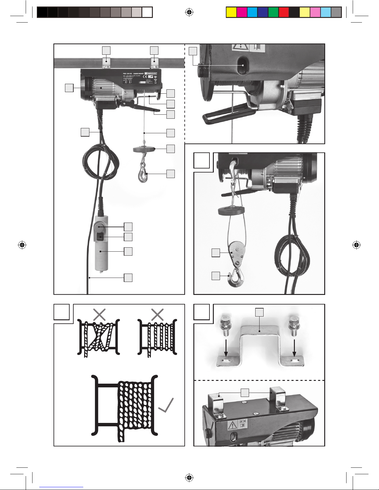
Parts description
1
Mounting bracket
2
Mounting opening for hook in deflection
operation
3
Hoisting drum
4
Maximum cable length lever
5
Auto-stop mechanism lever
6
Steel cable
7
Shut-off weight
8
Hook
9
Emergency stop switch
10
Push button
11
Remote control unit
12
Mains lead
13
Control lead
14
Motor
15
Deflection pulley
16
Additional hook
Scope of delivery
1 Cable hoist
2 Mounting bracket with mounting materials (Fig. C)
1 Deflection pulley with additional hook and moun-
ting materials (see Fig. D)
1 Set of instructions for use
Technical Data
Voltage: 230 V~ 50 Hz
Rated current: 2.2 A
Power input: 500 W
Duty type: S3 20 % 10 min
Rated load: 125 / 250 kg (without / with
deflection pulley)
Hoisting height: 11.5 / 5.7 m (without / with
deflection pulley)
Rated speed: 8 / 4 m / min (without / with
deflection pulley)
Steel cable
diameter: 3.0 mm
Steel cable
tensile strength: 1870 N / mm
2
Insulating level: B
Degree of
protection: IP54
Power unit class: M1
Net weight: 9.3 kg
Gross weight: 10.5 kg
Duty type 3–20 % - 10 min: S3 = Intermittent duty
without the effect of starting. During a 10 min period
the max. operating time is 20 % (2 min).
Mechanical group M1.
The rated power of the device does not vary with
the position of the load.
The value of the A-rated noise emission in the oper
ator
position is less than 70 dB.
The cable hoist must be operated at ambient temperatures from 0 °C to 40 °C and a relative humidity
below 85 %. Height above sea level: max. 1000 m.
100684_par_Seilhebelzug_content_GB_IE_CY.indd 6 02.07.14 12:41
Page 7
7 GB/IE/CY
During transport and storage the temperature may
be between -25 °C and 55 °C. The maximum permissible temperature is 70 °C.
Important safety
instructions
Please read all safety informati
on
and instructions. Failure to observe the safety information and instructions can result in electric shock,
fire and / or serious injury. Keep all safety instruc
tions
and directions for future use!
Always verify the mains voltage matches the
voltage on the nameplate. If the mains voltage
is not suitable, abnormal device operation and
personal injury may result.
The power supply must have earthing and be
protected by an earth leakage circuit breaker.
Hoisting loads exceeding the rated load is pro-
hibited.
Only use the device for the intended purpose.
Never hoist persons with the cable hoist.
Do not unplug from the socket by the cable.
Keep the cable away from heat, oil, and sharp
edges.
Never attempt to hoist fixed or blocked loads.
Remove the mains plug from the socket after
every use.
Keep children and other unauthorised persons
away from the device.
Pulling loads sideways or from one side is pro-
hibited. Prevent the load from swinging.
Ensure the hook 8 moves in the direction shown
on the push button
10
.
Regularly check the cable hoist for damage.
The push button
10
must be in good condition.
Always have repairs and maintenance performed
by an electrician at an authorised specialist
workshop. repairs must be performed by an
electrician to prevent operator accidents.
Avoid rapid start-up and powering off (inching
mode).
Always be attentive whilst operating the cable
hoist.
Never stand or work below the hoisted load.
Hoisting stuck or jammed loads is prohibited.
Always pull the mains plug before executing
settings on the device.
The cable hoist is not suitable for transporting
hot and / or molten materials; the cable hoist is
further not suitable for use in low temperatures
or in environments with severe weather (see
Technical Data).
The service life of the cable hoist is approx.
8000 cycles (excl. wear parts). Once the hoist
has reached 8000 cycles all mechanical parts
must be inspected and overhauled.
Read and understand the operating instructions
before using the cable hoist.
Ensure the operator is familiar with the functiona-
lity of the device and how it should be operated.
The user must always operate the device in
accordance with the operating instructions.
The hoist is not intended for continuous operation.
The duty type is:
Intermittent duty without the effect of starting.
After opening the packaging, please inspect the
device, the steel cable, the hooks, the maximum
cable length lever and the auto-stop mechanism
lever for transport damage.
Safety notices
specific to the device
The user must hoist the load from the ground at
the slowest possible speed. The cable must be
tightened when the load is being hoisted.
The electric cable hoist is not equipped with
a rated power limit. Therefore do not continue
attempting to hoist the load if the overheat protection limits operation. In this event the load
exceeds the rated power of the cable hoist.
Do not leave suspended loads unattended wit-
hout taking the appropriate safety precautions.
Secure the device with a 10 A fuse or a 10 A
earth leakage circuit breaker to protect the
electric circuit.
Do not use the lever 4 / 5 as a routine stop.
These are only intended as emergency stopping
devices.
Introduction / Important safety instructions / Safety notices specific to the device
100684_par_Seilhebelzug_content_GB_IE_CY.indd 7 02.07.14 12:41
Page 8

8 GB/IE/CY
Before beginning, verify the steel cable 6 is
wound around the drum
3
correctly and the
clearance between the turns is smaller than the
steel cable (Fig. B).
Before using
Mounting (see Fig. C)
Secure the cable hoist to a square pipe / boom
using the 2 mounting brackets
1
. The dimensions of the square pipe / boom must correspond
with the size of the mounting bracket
1
and
must be able to bear double the rated load.
Note: We recommend contact a qualified
technician for this purpose.
Screw the mounting brackets 1 to the cable
hoist (also see Fig. C).
Tighten all screws.
Note: A qualified technician should inspect
the anchor of the square tube / boom before
putting the device into service.
Note: The cable hoist motor
14
is equipped
with a thermostat switch. The motor 14 may
therefore stop whilst operating the cable hoist; it will
automatically restart once it has cooled down.
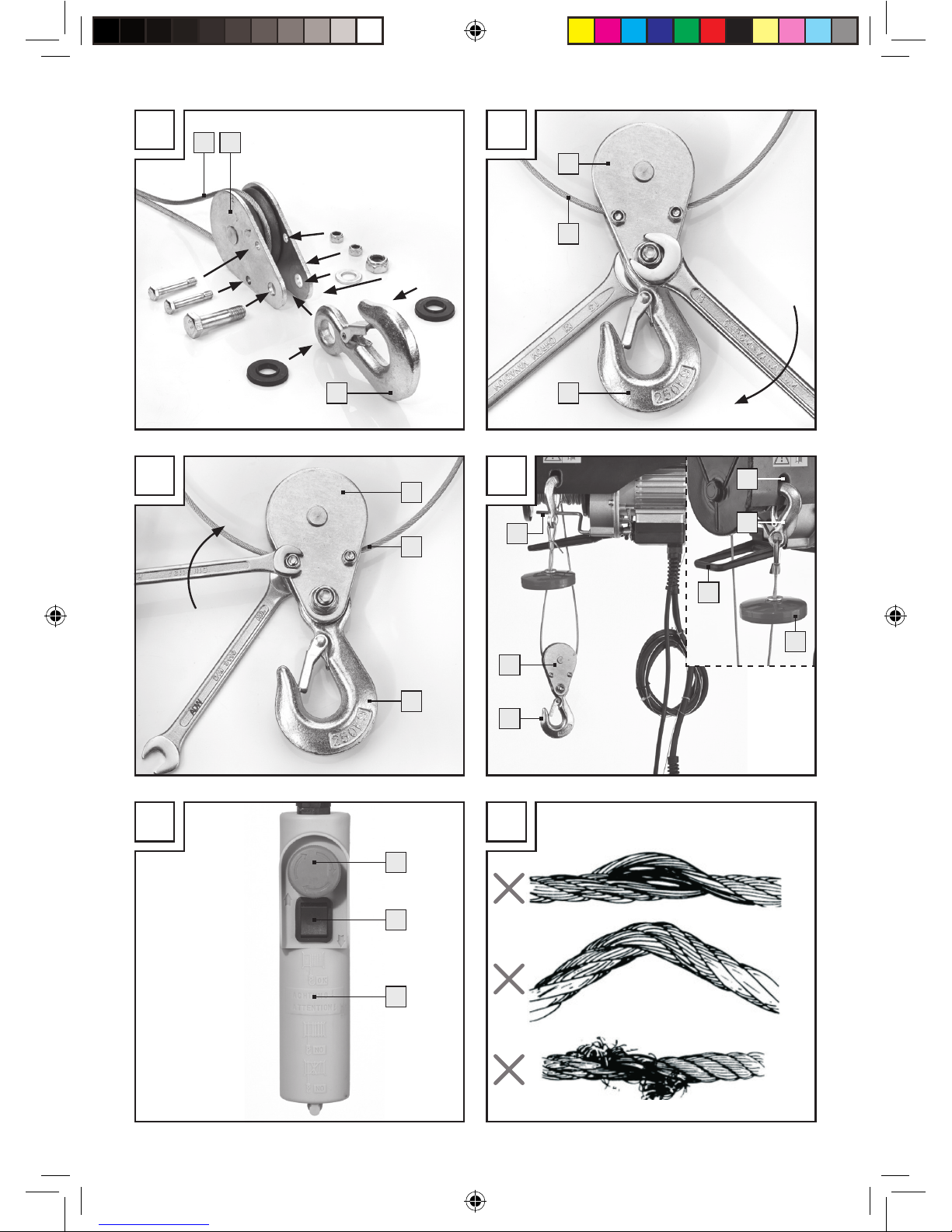
Setting up the pulley function
(see Fig. D–G)
The cable hoist is equipped with a pulley 15 and
an additional hook
16
. When used correctly, the
cable hoist can lift double the load.
Install the pulley 15 and additional hook 16
as shown in figures D–G.
Hook the fixed hook 8 into the fixing opening
2
(see Fig. G). The load will now be lifted with
two steel cables and the cable hoist can therefore lift double the load.
Operation
Putting the cable hoist
into service
The user must hoist the load from the ground at
the slowest possible speed. The cable must be
tightened when the load is being hoisted.
Secure the device with a 10 A fuse or a 10 A
earth leakage circuit breaker to protect the
electric circuit.
Before beginning, verify the steel cable 6 is
wound around the drum
3
correctly and the
clearance between the turns is smaller than the
steel cable (Fig. B).
Remove the adhesive tape from the cable drum
3
prior to first use.
Ensure the load is properly secured to the hook
8
or, for pulley operation, the additional hook
16
, and always maintain a distance to the
load and the steel cable
6
.
Operating the cable hoist
Check if the emergency stop switch 9 is
pressed.
Turn the emergency stop switch 9 clockwise
to release.
Press the push button ▲ 10 to hoist the load
(see Fig. H).
Press the push button ▼ 10 to lower the load
(see Fig. H).
Auto-stop mechanism lever
5
When the maximum hoisting height has been
reached,
the shut-off weight 7 will push the lever 5 up
ward.
This engages a limit switch and the load can no
longer be hoisted.
Maximum cable length lever
4
When the load reaches the lowest possible position,
an end switch is activated, preventing the load from
being lowered further. This end switch also prevents
the cable hoist from being operated in the wrong
direction (hook moving opposite of the direction
indicated on the push button
10
).
Operation / Cleaning, maintenance and ordering spare parts / Disposal
Safety notices specific to the device / Before using / Operation
100684_par_Seilhebelzug_content_GB_IE_CY.indd 8 02.07.14 12:41
Page 9
9 GB/IE/CY
ATTENTION! In the event of an emergency, immediately activate the emergency stop switch
9
to stop
the cable hoist. The cable hoist cannot be operated
if the emergency stop switch has been activated.
Cleaning, maintenance and
ordering spare parts
Cleaning
ATTENTION! Unplug the mains plug from the
socket before cleaning.
Do not use cleaners or solvents; these could
affect the plastic parts of the device.
Ensure water cannot penetrate the housing.
Keep safety devices, venting slots and the motor
housing as dust and dirt free as possible.
Rub the device down with a clean cloth or
blow out with compressed air at a low pressure
setting.
Regularly clean the device with a damp cloth and
a little soft soap.
Note: We recommend cleaning the device
immediately after every use.
Maintenance
ATTENTION! Verify the device is not connected to
the mains when performing care.
Below: A cycle corresponds to moving a load up
and down once.
Periodic inspection corresponds to an inspection
after 100 cycles.
Periodically check the end switches on the cable
hoist are working properly (check without load).
Test as follows: When the cable reaches the
maximum hoisting height the auto-stop mecha-
nism lever
5
is activated. The motor 14 must
now stop. When the steel cable
6
is unwound
as far as possible, the maximum cable length
lever
4
is activated. The motor 14 must now
stop.
Periodically check the power cable 12 and the
control lead
13
.
Lubricate the steel cable 6 and pulley 15 every
200 cycles.
Every 30 cycles verify the entire steel cable 6
is in good working order in accordance with Figure I. If damaged, it must be replaced with a
steel cable corresponding with the technical data.
Every 1000 cycles check the screws on the
mounting bracket
1
and pulley 15 are tight.
Every 1000 cycles verify the hooks 8 / 16
and the pulley
15
are in good condition.
Verify the emergency stop switch 9 and push
buttons
10
are in good condition before every
use.
Check the brake system every 1000 cycles. If
the motor
14
emits unusual noises or is unable
to hoist the rated load, the brake system may
need to be overhauled:
- Replace damaged or worn parts and keep
the associated maintenance documentation.
- Please contact an authorised service centre
for unscheduled maintenance work.
Disposal
The device is packaged to protect it from transport
damage. This packaging is a raw material and therefore reusable or may be recycled. The device and
its accessories are made from various materials, e.g.
metal and plastics.
Dispose of defective components through toxic waste
disposal. Contact the speciality retailer or your municipal government for information!
Do not dispose of power
tools in household waste!
In accordance with European Directive 2012 / 19 /
EU
on waste electrical and electronic equipment and
its implementation into national legislation, worn
out power tools must be collected separately and
recycled in an environmentally friendly fashion.
Operation / Cleaning, maintenance and ordering spare parts / Disposal
100684_par_Seilhebelzug_content_GB_IE_CY.indd 9 02.07.14 12:41
Page 10

10 GB/IE/CY
Alternate recycling option for return
request:
The owner of the electrical equipment is alternatively
obligated to contribute to proper recycling in place
of a return in the case of abandonment. For this purpose the used equipment may also be taken to a
collection site disposing within the terms of the national Closed Substance Cycle Waste Management
Act. This does not apply to accessories attached to
the used equipment and implements without electri
cal
components.
Warranty / Service centre
We provide a 3-year warranty covering faults in
materials or manufacture of the device from the
purchase date.
The warranty does not cover:
· Damage from improper use.
· Wear parts.
· Defects the customer was aware of at the time
of purchase.
· Damage caused by the customer.
T
his warranty does not affect the customer‘s legal rights.
The customer must provide proof of purchase in order
for any warranty claims within the warranty period to
be honoured. Warranty claims must be filed within
3 years from the date of purchase.
In the event of a warranty claim, the customer has
the right to have the goods repaired by our own
workshop or a workshop authorised by us. The device must not be opened for any reason. Opening
or modifying the device invalidates the warranty.
This warranty does not grant any additional rights to
the customer (based on the warranty). Complaints
are often initiated by difficulties encountered during
use. Many of these complaints can be resolved by
telephone or email. Please contact our Service Hotline in the first instance, before you return the device
to the manufacturer.
GB
Unit 55 Romsey Industrial Estate, Romsey
GB - Hampshire SO51 OHR
T: +44 845 0766158
F: +44 1794 514882
IE
Unit 55 Romsey Industrial Estate, Romsey
GB - Hampshire SO51 OHR
T: +44 1794 834250
F: +44 1794 514882
IAN 100684
Please have your receipt and the article number
(e.g. IAN 12345) ready as your proof of purchase
when enquiring about your product.
Ordering spare parts
When ordering replacement parts you
should give the following information:
- Device model
- Device item number
- device ID number
Declaration of conformity
We, MATRIX GMBH, officer responsible for documentation: Mr. Joachim Lichtl, POSTAUER STR. 26,
84109 WÖRTH / ISAR, GERMANY, hereby declare
this product to comply with the following standards,
normative documents and EC directives:
2006 / 42 / EC
2006 / 95 / EC
2004 / 108 / EC
2011 / 65 / EU
Disposal / Warranty / Service centre / Declaration of conformity
100684_par_Seilhebelzug_content_GB_IE_CY.indd 10 02.07.14 12:41
Page 11

11 GB/IE/CY
Declaration of conformity
applicable harmonised standards
EN 14492-2+A1
EN 60204-32
EN 55014-1
EN 55014-2
EN 61000-3-2
EN 61000-3-3
Type / Description of product:
Cable winch PSZ 250 B2
Year of manufacture: 2014
Wörth / Isar, 31.05.2014
Joachim Lichtl
- Managing Director -
We reserve the right to make technical modifications
in the course of product development.
100684_par_Seilhebelzug_content_GB_IE_CY.indd 11 02.07.14 12:41
Page 12

12
100684_par_Seilhebelzug_content_GB_IE_CY.indd 12 02.07.14 12:41
Page 13

13 GR/CY
Sicherheit / BedienungΠίνακας περιεχομένων
Εισαγωγή
Χρήση σύμφωνα με τις προδιαγραφές ..........................................................................................Σελίδα 14
Περιγραφή μερών ............................................................................................................................Σελίδα 14
Περιεχόμενα παράδοσης ................................................................................................................Σελίδα 14
Τεχνικά χαρακτηριστικά ...................................................................................................................Σελίδα 14
Σημαντικές υποδείξεις ασφαλείας ...........................................................................Σελίδα 15
Ειδικές για τη συσκευή υποδείξεις ασφαλείας ...............................................Σελίδα 16
Πριν από τη θέση σε λειτουργία
Εγκατάσταση ....................................................................................................................................Σελίδα 16
Ορισμός λειτουργίας τροχαλίας ....................................................................................................Σελίδα 16
Χειρισμός
Θέση σε λειτουργία του ανυψωτήρα καλωδίου .............................................................................Σελίδα 16
Λειτουργία ανυψωτήρα ....................................................................................................................Σελίδα 17
Καθαρισμός, συντήρηση και παραγγελία ανταλλακτικών
Καθαρισμός .....................................................................................................................................Σελίδα 17
Συντήρηση ........................................................................................................................................Σελίδα 17
Απόρριψη ....................................................................................................................................Σελίδα 18
Εγγύηση / Service ..................................................................................................................Σελίδα 18
Παραγγελία ανταλλακτικών .............................................................................................................Σελίδα 19
Δήλωση συμμόρφωσης ....................................................................................................Σελίδα 19
100684_par_Seilhebelzug_content_GB_IE_CY.indd 13 02.07.14 12:41
Page 14

14 GR/CY
Εισαγωγή
Γερανακι ανυψωσης φορτιου
PSZ 250 B2
Εισαγωγή
Πριν από τη θέση σε λειτουργία και την
πρώτη χρήση εξοικειωθείτε με τη συσκευή.
Για τον σκοπό αυτό διαβάστε προσεκτικά
τις παρακάτω οδηγίες χρήσης και τις σημαντικές
υποδείξεις ασφαλείας. Χρησιμοποιείτε την συσκευή
μόνον, όπως περιγράφεται και για τους δεδομένους
τομείς εφαρμογής. Φυλάξτε τις παρούσες οδηγίες.
Σε περίπτωση παράδοσης της συσκευής σε τρίτους
παραδώστε επίσης και όλα τα έγγραφα.
Χρήση σύμφωνα με τις
προδιαγραφές
Ο ανυψωτήρας καλωδίου για ανύψωση και χαμήλωμα
φορτίων σε κλειστούς χώρους αντίστοιχα με την ισχύ
της συσκευής. Η συσκευή επιτρέπεται να χρησιμοποιείται
μόνο όπως περιγράφεται. Οποιαδήποτε περαιτέρω
χρήση δεν είναι σύμφωνη με τις προδιαγραφές. Για
ζημιές ή τραυματισμούς οποιουδήποτε είδους που
προκύπτουν από αυτό ευθύνεται ο χρήστης / χειριστή
ς
και όχι ο κατασκευαστής. Παρακαλούμε προσέχετε
ότι οι συσκεύες μας δεν είναι σχεδιασμένες για
οικιακή, εργαστηριακή ή βιομηχανική χρήση. Δεν
αναλαμβάνουμε καμία παροχή εγγύησης αν η συσκευ
ή
χρησιμοποιηθεί σε επαγγελματικές, εργαστηριακές
ή βιομηχανικές επιχειρήσεις καθώς και σε όμοιες
δραστηριότητες.
Περιγραφή μερών
1
Πλαίσιο στερέωσης
2
Άνοιγμα στερέωσης για άγκιστρο κατά την
λειτουργία αντιστροφής ταχυτήτων
3
Τύμπανο περιέλιξης
4
Μοχλός για μέγιστο μήκος καλωδίου
5
Μοχλός τουη αυτόματου μηχανισμού παύσης
6
Ατσάλινο καλώδιο
7
Βάρος απενεργοποίησης
8
Άγκιστρο
9
Διακόπτης απενεργοποίησης εκτάκτου ανάγκης
10
Κομβίο πίεσης
11
Τηλεχειριστήριο
12
Καλώδιο ηλεκτρικού δικτύου
13
Σύρμα πιλότος
14
Κινητήρας
15
Τροχαλία αναστροφής
16
Πρόσθετα άγκιστρα
Περιεχόμενα παράδοσης
1 Ανυψωτήρας καλωδίου
2 Πλαίσια στερέωσης με υλικό εγκατάστασης (Εικ. C)
1 Τροχαλία αναστροφής με πρόσθετα άγκιστρα
και υλικό εγκατάστασης (β. Εικ. D)
1 Οδηγίες χρήσης
Τεχνικά χαρακτηριστικά
Τάση: 230 V∼ 50 Hz
Ονομαστικό ρεύμα: 2,2 A
Κατανάλωση ισχύος: 500 W
Είδος λειτουργίας: S3 20 % 10 λεπτά
Ονομαστικό φορτίο: 125 / 250 kg (χωρίς / με
τροχαλία αναστροφής)
Ύψος ανύψωσης: 11,5 / 5,7 m (χωρίς / με
τροχαλία αναστροφής)
Ονομαστική ταχύτητα: 8 / 4 m / min (χωρίς/με
τροχαλία αναστροφής)
Διάμετρος
του ατσάλινου καλωδίου: 3,0 mm
Αντοχή εφελκυσμού
του ατσάλινου καλωδίου: 1870 N / mm
2
Κατηγορία μόνωσης: B
Είδος προστασίας: IP54
Κατηγορία κινητήρα: Μ1
Καθαρό βάρος: 9,3 kg
Bruttogewicht: 10,5 kg
Είδος λειτουργίας 3–20 % - 10 τουλ.: S3 = Περιοδική λειτουργία χωρίς επίδραση της διαδικασίας
εκκίνησης. Κατά την διάρκεια ενός χρονικού διαστήματος 10 λεπτών κυμαίνεται ο μέγ. χρόνος
λειτουργίας στο 20 % 2 λεπτά.
Η μηχανική ομάδα είναι Μ1.
100684_par_Seilhebelzug_content_GB_IE_CY.indd 14 02.07.14 12:41
Page 15

15 GR/CY
Η ονομαστική ισχύς της συσκευής δεν μεταβάλλεται
με την θέση του φορτίου.
Η τιμή της Α-βαθμολογημένης εκπομπής θορύβου
στην θέση λειτουργίας είναι χαμηλότερη από 70 dB.
Ο ανυψωτήρας καλωδίου πρέπει να λειτουργεί σε
εύρος θερμοκρασιών μεταξύ 0 °C και 40 °C σχετικής
υγρασίας κάτω από 85 %. Ύψος πάνω από την
στάθμη της θάλασσας: μέγ. 1000 m.
Για μεταφορά και αποθήκευση επιτρέπεται να
κυμαίνεται η θερμοκρασία μεταξύ -25 °C και 55 °C.
Η μέγιστη επιτρεπτή θερμοκρασία είναι 70 °C.
Σημαντικές υποδείξεις
ασφαλείας
Διαβάστε όλες τις
υποδείξεις ασφάλειας και οδηγίες. Αδυναμία τήρηση
ς
των υποδείξεων ασφάλειας και των οδηγιών μπορεί
να έχει ηλεκτροπληξία, πυρκαγιά και / ή σοβαρούς
τραυματισμούς ως συνέπειες. Φυλάξτε όλες τις
υποδείξεις ασφάλειας και τις οδηγίες για μελλοντική
χρήση!
Ε
λέγχεται πάντοτε αν η ονομαστική τάση αντιστοι
χεί
στην τάση της πινακίδας τύπου. Για την περίπτωση
,
που η ονομαστική τάση δεν είναι κατάλληλη,
μπορεί αυτή να οδηγήσει σε ανώμαλη εργασία
της συσκευής και σε ζημιές σε πρόσωπα.
Η παροχή ρεύματος πρέπει να διαθέτει μια
γείωση και να είναι ασφαλισμένη με εναν διακόπ
τη
προστασίας ρεύματος βραχυκύκλωσης.
Απαγορεύεται να ανυψώνετε φορτία, που
υπερβαίνουν το ονομαστικό φορτίο.
Χρησιμοποιείτε την συσκευή μόνο για τον σκοπό,
για τον οποίο προορίζεται. Ποτέ μην ανυψώνετε
πρόσωπα με τον ανυψωτήρα καλωδίου.
Μην χρησιμοποιείτε το καλώδιο, για να τραβήξετε
τον ρευματολήπτη από την πρίζα. Κρατήστε το
καλώδιο μακριά από θερμότητα, λάδι, αιχμηρές
ακμές.
Ποτέ μην προσπαθείτε να ανυψώσετε σταθερά
ή μπλοκαρισμένα φορτία.
Έπειτα από κάθε χρήση, βγάλτε τον ρευματολήπτη
από την πρίζα.
Κρατάτε παιδιά και άλλα μη εξουσιοδοτημένα
άτομα μακριά από την συσκευή.
Απαγορεύεται να τραβάτε φορτία πλευρικά ή α
πό
μία άλλη πλευρά. Αποφεύγετε μια ταλάντωση
του φορτίου.
Βεβαιωθείτε ότι το άγκιστρο 8 κινείται στην
ίδια κατεύθυνση όπως δείχνει το κομβίο
πίεσης
10
.
Ελέγχετε τον ανυψωτήρα καλωδίου τακτικά για
φθορές. Το κομβίο πίεσης
10
πρεπει να είναι
σε καλή κατάσταση.
Επιτρέπεται επισκευές και εργασίες συντήρησης
να πραγματοποιούνται μόνο από εξουσιοδοτημένα
συνεργεία μέσω ενός ηλεκτροτεχνίτη. Επισκευές
επιτρέπεται να πραγματοποιούνται μόνο από
ηλεκτροτεχνικό προσωπικό, διαφορετικά μπορούν
να προκύψουν ατυχήματα για τον χειριστή.
Απφεύγετε μια γρήγορη ενεργο- και
απενεργοποίηση (λειτουργία Jog).
Να είστε πάντοτε προσεκτικοί κατά την
λειτουργία του ανυψωτήρα καλωδίου.
Μην στέκεστε ή εργάζεστε κάτω από το ανυψωμέ
νο
φορτίο.
Δεν επιτρέπεται να ανυψώνετε σταθερά ή
κολλημένα φορτία.
Τραβήξτε πάντα τον ρευματολήπτη, προτού
εκτελέσετε ρυθμίσεις στη συσκευή.
Ο ανυψωτήρας καλωδίου δεν είναι κατάλληλος
για μεταφορά θερμών και / ή λιωμένων μαζών,
επιπλέον ο ανυψωτήρας δεν είναι κατάλληλος
για την εφαρμογή σε χαμηλές θερμοκρασίες
και σε περιβάλλον έντονης κακοκαιρίας (β.
τεχνικά χαρακτηριστικά).
Η διάρκεια χρήσης του ανυψωτήρα καλωδίου
είναι περ. 8000 κύκλοι (εξαιρ. αναλώσιμων
μερών). Αν η παρτίδα των 8000 κύκλων έχει
λήξει, πρέπει όλα τα τα μηχανικά μέρη να
ελέγχονται και να αντικαθίστανται πλήρως.
Διαβάστε και καταλάβετε αυτές τις οδηγίες
χ
ρήσης, προτού χρησιμοποιήσετε τον ανυψωτήρα
καλωδίου.
Βεβαιωθείτε ότι ο χειριστής ξέρει, πως λειτουργεί
η συσκευή, και πως θα έπρεπε να γίνεται ο
χειρισμός της.
Ο χρήστης πρέπει πάντα να λειτουργεί σε
συμφωνία με τις οδηγίες χρήσης.
Ο ανυψωτήρας δεν είναι σχεδιασμένος για
συνεχή λειτουργία. Το είδος λειτουργίας είναι:
Εισαγωγή / Σημαντικές υποδείξεις ασφαλείας
100684_par_Seilhebelzug_content_GB_IE_CY.indd 15 02.07.14 12:41
Page 16

16 GR/CY
Περιοδική λειτουργία χωρίς επιρροή της
διαδικασίας εκκίνησης.
Μετάτο άνοιγμα της συσκευασίας επιθεωρήστε
παρακαλούμε την συσκευή, το ατσάλινο καλώδιο
,
τα άγκιστρα, τον μοχλό για μέγιστο μήκος
καλωδίου και τον μοχλό του αυτόματου
μηχανισμού παύσης για πιθανές ζημιές
μεταφοράς.
Ειδικές για τη συσκευή
υποδείξεις ασφαλείας
Ο χρήστης πρέπει να ανυψώνει το φορτίο από
το έδαφος με την χαμηλότερη δυνατή
ταχύτητα. Το καλώδιο πρέπει να είναι τεντωμένο
όταν ανυψώνεται το φορτίο.
Ο ηλεκτρικός ανυψωτήρας καλωδίου δεν είναι
εξοπλισμένος με έναν περιοριστή ονομαστικής
ισχύος. Για αυτό μην συνεχίζετε να προσπαθείτε
να ανυψώσετε το φορτίο όταν η προστασία
υπερθέρμανσης περιορίζει την λειτουργία. Το
φορτίο υπερβαίνει σε αυτή την περίπτωση την
ονομαστική ισχύ του ανυψωτήρα καλωδίου.
Μην αφήνετε κρεμασμένα φορτία χωρίς
επιτήρηση χωρίς να έχουν ληφθεί οι αντίστοιχες
προδιαγραφές ασφάλειας.
Ασφαλίστε τη συσκευή με μια ασφάλεια 10 A
ή με έναν διακόπτη προστασίας ρεύματος
βραχυκυκλώματος 10 A για να προστατέψετε
το κύκλωμα ρεύματος.
Μην χρησιμοποιείτε τους μοχλούς 4 / 5 ως
διάταξη παύσης ρουτίνας. Αυτοί λειτουργούν
μόνο ως διάταξη παύσης σε έκτακτη ανάγκη.
Προτού ξεκινήσετε, βεβαιωθείτε, ότι το ατσάλινο
καλώδιο
6
είναι ορθά ξετυλιγμένο από το
τύμπανο περιέλιξης
3
και η απόσταση μεταξύ
των στροφών είναι μικρότερη από το ατσάλινο
καλώδιο (Εικ. B).
Πριν από τη θέση σε λειτουργία
Εγκατάσταση (β. Εικ. C)
Στερεώστε τον ανυψωτήρα καλωδίου με τα
2 πλαίσια στερέωσης
1
σε έναν βραχιόνα
τετράγωνου σωλήνα / κούνια. Οι διαστάσεις
του βραχίονα τετράγωνου σωλήνα / κούνιας
πρέπει να συμφωνούν με το μέγεθος του
πλαισίου
στερέωσης
1
και αυτός / αυτή πρέπει να μπορεί
να φέρει το διπλό ονομαστικό φορτίο.
Υπόδειξη: Σας συνιστούμε, επ‘ αυτού να
επικοινωνήσετε με έναν εξειδικευμένο τεχνικό.
Βιδώστε το πλαίσιο στερέωσης 1 στον
ανυψωτήρα καλωδίου (β. επίσης Εικ. C).
Σφίξτε όλες τις βίδες.
Υπόδειξη: Πριν την θέση σε λειτουργία ένας
εξειδικευμένος τεχνικός πρέπει να ελέγξει την
αγκύρωση του τετράγωνου σωλήνα / βραχίονα.
Υπόδειξη: Ο κινητήρας
14
του ανυψωτήρα
είναι εξοπλισμένος με έναν διακόπτη θερμοστάτη.
Κατά την διάρκεια της λειτουργίας του ανυψωτήρα
καλωδίου μπορεί για αυτό να προκύψει παύση
του κινητήρα
14
, αυτός θα λειτουργήσει πάλι
αυτόματα μόλις κρυώσει.
Ορισμός λειτουργίας
τροχαλίας (β. Εικ. D–G)
Ο ανυψωτήρας καλωδίου είναι εξοπλισμένος με
μια τροχαλία αναστροφής
15
και ένα πρόσθετο
άγκιστρο
16
. Σε ορθή χρήση μπορεί ο ανυψωτήρας
καλωδίου να ανυψώσει το διπλάσιο φορτίο.
Εγκαταστήστε την τροχαλία αναστροφής 15 και
τα πρόσθετα άγκιστρα
16
όπως παρουσιάζεται
στις εικόνες D–G.
Αναρτήστε το σταθερά εγκατεστημένο άγκιστρο 8
στο άνοιγμα στερέωσης 2 (β. Εικ. G). Ανυψώστ
ε
τώρα το φορτίο με την βοήθεια των δυο ατσάλινω
ν
καλωδίων, έτσι μπορεί ο ανυψωτήρας καλωδίου
να ανυψώσει το διπλάσιο φορτίο.
Χειρισμός
Θέση σε λειτουργία του
ανυψωτήρα καλωδίου
Ο χρήστης πρέπει να ανυψώνει το φορτίο από
το έδαφος με την χαμηλότερη δυνατή ταχύτητα.
Το καλώδιο πρέπει να είναι τεντωμένο όταν
ανυψώνεται το φορτίο.
… / Ειδικές για τη συσκευή … / Πριν από τη θέση σε λειτουργία / Χειρισμός
100684_par_Seilhebelzug_content_GB_IE_CY.indd 16 02.07.14 12:41
Page 17

17 GR/CY
Ασφαλίστε τη συσκευή με μια ασφάλεια 10 A ή
με έναν διακόπτη προστασίας ρεύματος
βραχυκυκλώματος 10 A για να προστατέψετε
το κύκλωμα ρεύματος.
Προτού ξεκινήσετε, βεβαιωθείτε, ότι το ατσάλινο
καλώδιο
6
είναι ορθά ξετυλιγμένο από το
τύμπανο περιέλιξης
3
και η απόσταση μεταξύ
των στροφών είναι μικρότερη από το ατσάλινο
καλώδιο (Εικ. B).
Απομακρύνετε πριν την πρώτη χρήση την αυτοκόλ
-
λητη ταινία από το τύμπανο περιέλιξης
3
.
Βεβαιωθείτε, ότι το φορτίο είναι ασφαλισμένο
σύμφωνα με τις προδιαγραφές στο άγκιστρο
8
ή κατά την λειτουργία τροχαλίας στο πρόσθετο
άγκιστρο
16
και κρατάτε πάντα απόσταση από
το φορτίο και το ατσάλινο καλώδιο
6
.
Λειτουργία ανυψωτήρα
Ελέγχετε, αν ο διακόπτης απενεργοποίησης
εκτάκτου ανάγκης
9
είναι πιεσμένος.
Στρέψτε τον διακόπτη απενεργοποίησης εκτάκτου
ανάγκης 9 δεξιόστροφα για να τον ξεκλειδώσετε.
Πιέστε το κομβίο πίεσης στην φορά ▲ 10 για
ανύψωση του φορτίου (β. Εικ H).
Πιέστε το κομβίο πίεσης στην φορά ▼ 10 για
χαμήλωμα του φορτίου (β. Εικ H).
Μοχλός του αυτόματου μηχανισμού
παύσης
5
‚Οταν επιτευχθεί το μέγιστο ύψος ανύψωσης, πιέζει
το βάρος απενεργοποίησης 7 τον μοχλό 5
προς
τα πάνω. Με αυτό αγγίζεται ένας τερματικός διακόπτη
ς
και το φορτίο δεν μπορεί να ανυψωθεί περισσότερο.
Μοχλός για μέγιστο μήκος καλωδίου
4
Όταν το φορτίο έχει φτάσει στην όσο το δυνατόν πιο
χαμηλή θέση, αγγίζεται ένας τερματικός διακόπτης,
ο οποίος καθιστά αδύνατο ένα περαιτέρω χαμήλωμα
του φορτίου. Αυτός ο τερματικός διακόπτης
αποτρέπει επίσης μια λειτουργία του ανυψωτήρα
καλωδίου στην λάθος κατεύθυνση (το άγκιστρο
κινείται στην αντίθετη προς το κομβίο πίεσης
10
εμφανιζόμενη κατεύθυνση).
ΠΡΟΣΟΧΗ! Σε περίπτωση έκτακτης ανάγκης
πιέστε αμέσως τον διακόπτη απενεργοποίησης
έκτακτής ανάγκης
9
για να σταματήσετε τον
ανυψωτήρα καλωδίου. Η λειτουργία του ανυψωτήρα
καλωδίου δεν είναι δυνατή, όταν έχει πιεστεί ο
διακόπτης απενεργοποίησης έκτακτης ανάγκης.
Καθαρισμός, συντήρηση και
παραγγελία ανταλλακτικών
Καθαρισμός
ΠΡΟΣΟΧΗ! Τραβήξτε πριν από όλες τις εργασίες
καθαρισμού το βύσμα δικτύου από την πρίζα.
Μην χρησιμοποιείτε καθαριστικό ή διαλυτικό
μέσο; αυτά θα μπορούσαν να ερεθίσουν τα
πλαστικά μέρη της συσκευής.
Προσέχετε ώστε να μην μπορεί να καταλήξει
καθόλου νερό στο εσωτερικό της συσκευής.
Διατηρείτε τις διατάξεις ασφάλειας, σχισμές
αερισμού και περίβλημα κινητήρα όσο το
δυνατόν καθαρές από σκονη και βρωμιά.
Τρίβετε την συσκευή με ένα καθαρό πανί ή
καθαρίστε την με πεπιεσμένο αέρα σε χαμηλή
πίεση.
Καθαρίζετε την συσκευή τακτικά με ένα υγρό
πανί και λίγο μαλακό σαπούνι.
Υπόδειξη: Συνιστάται να καθαρίζετε την
συσκευή απευθείας μετά από κάθε χρήση.
Συντήρηση
ΠΡΟΣΟΧΗ! Πάντα να βεβαιώνεστε, ότι η συσκευή
δεν είναι συνδεδεμένη με το δίκτυο ρεύματος, όταν
την φροντίζετε.
Παρακάτω: Ένας κύκλος αντιστοιχεί σε μια
ανοδικη και καθοδική κίνησης ενός φορτίου.
Περιοδική εξέταση αντιστοιχεί σε μια εξέταση μετά
από 100 κύκλους.
Εξετάζεται περιοδικά, ότι ο τερματικός
διακόπτης του ανυψωτήρα καλωδίου λειτουργεί
σύμφωνα με τις προδιαγραφές (εξετάστε χωρίς
φορτίο).
Χειρισμός / Καθαρισμός, συντήρηση και παραγγελία ανταλλακτικών
100684_par_Seilhebelzug_content_GB_IE_CY.indd 17 02.07.14 12:41
Page 18

18 GR/CY
Η εξέταση πραγματοποιείται ακολούθως:
Όταν το καλώδιο φτάσει το μέγιστο ύψος
ανύψωσης, αγγίζεται ο μοχλός του αυτόματου
μηχανισμού παύσης
5
. Ο κινητήρας 14 πρέπει
τώρα να σταματάει. Αν το ατσάλινο καλώδιο
6
είναι όσο το δυνατό περισσότερο ξετυλιγμένο,
ενεργοποιείται ο μοχλός για μέγιστο μήκος
καλωδίου
4
. Ο κινητήρας 14 πρέπει τώρα να
σταματάει.
Εξετάζετε περιοδικά το καλώδιο δικτύου 12
και το σύρμα πιλότο
13
.
Λ
ιπαίνετε κάθε 200 κύκλους το ατσάλινο καλώδ
ιο
6
και την τροχαλία αναστροφής 15.
Ελέγχετε κάθε 30 κύκλους σύμφωνα με την
εικόνα I, αν το συνολικό ατσάλινο καλώδιο
6
είναι σε καλή κατάσταση. Σε περίπτωση που
είναι φθαρμένο, πρέπει να αντικατασταθεί από
ένα αντίστοιχο τεχνικών χαρακτηριστικών
ατσάλινο καλώδιο.
Εξετάζετε κάθε 1000, αν οι βίδες του πλαισίου
στερέωσης
1
και της τροχαλίας αντιστροφής
15
είναι καλά σφιγμένες.
Εξετάζετε κάθε 1000 κύκλους, αν τα άγκιστρα
8
/ 16 και η τροχαλία αντιστροφής 15 είναι
σε καλή κατάσταση.
Ελέγχετε πριν από κάθε χρήση του ανψωτήρα
καλωδίου αν ο διακόπτης απενεργοποίησης
έκτακτης ανάγκης
9
και το κομβίο πίεσης 10
είναι σε άθικτη κατάσταση λειτουργίας.
Κάθε 1000 κύκλους ελέγξτε το σύστημα φρένου.
Αν ο κινητήρας
14
κάνει ασυνήθιστους
θορύβους ή δεν μπορεί να ανυψώσει το
ονομαστικό φορτίο, είναι δυνατό, ότι το σύστημα
φρένου πρέπει να αντικατασταθεί πλήρως:
- Αντικαταστείτε ελαττωματικά ή φθαρμένα μέρη,
και αποθηκεύεται τα συναφή έγγραφα
συντήρησης.
- Για εργασίες συντήρησης εκτός σχεδίου
απευθυνθείτε παρακαλούμε σε ένα
εξουσιοδοτημένο κέντρο σέρβις.
Απόρριψη
Η συσκευή βρίσκεται για προστασία από
ζημιές μεταφοράς σε μια συσκευασία. Αυτή η
συσκευασία είναι πρώτη ύλη και μπορεί έτσι να
ξαναχρησιμοποιηθεί ή μπορεί να επιστραφεί στον
κύκλο πρώτων υλών. Η συσκευή και τα εξαρτήματα
της αποτελούνται από διάφορα υλικά, π.χ. μέταλλο
και πλαστικά.
Παραδώστε ελαττωματικά συστατικά μερη στην
απόρριψη ειδικών απορριμμάτων. Ενημερωθείτε
στο εξειδικευμένο κατάστημα ή στην κοινοτική
διαχείριση!
Απαγορεύεται η απόσυρση
ηλεκτρονικών εργαλείων μαζί
με τα οικιακά απορρίμματα!
Σύμφωνα με την Ευρωπαϊκή Οδηγία 2012 / 19 / EU
περί ηλεκτρικών συσκευών και παλιών ηλεκτρικών
συσκευών και της αναφοράς στο εθνικό δίκαιο, θα
πρέπει τα χρησιμοποιημένα ηλεκτρικά εργαλεία να
συλλέγονται σε ξεχωριστό χώρο και να ανακυκλώνοντα
ι
με οικολογικό τρόπο.
Εναλλακτικές ανακύκλωσης για απαίτηση
επιστροφής:
Ο ιδιοκτήτης της ηλεκτρικής συσκευής υποχρεούται
εναλλακτικά στην θέση της επιστροφής στην συνδρομ
ή
για την ανακύκλωση στην περίπτωση της αποποίησης
ιδιοκτησίας. Η παλιά συσκευή μπορεί για αυτό να
παραδοθεί σε ένα σημείο επιστροφής, το οποίο
πραγματοποιεί απόρριψη σύμφωνα με το εθνικό
εμπορικό δίκαιο και του νόμου απορριμάτων.
Ανεπηρέαστα είναι τα συμπεριλαμβανόμενα εξαρτήματ
α
παλιών συσκεύων και βοηθητικά μέσα χωρίς
συστατικά μέρη ηλεκτροδίων.
Εγγύηση / Service
Παρέχουμε εγγύηση 3 ετών από την ημερομηνία
αγοράς για σφάλματα υλικού και κατασκευής της
συσκευής.
Η εγγύηση δεν ισχύει:
· Σε περίπτωση βλαβών, οι οποίες οφείλονται
σε ανάρμοστη χρήση.
· Για εξαρτήματα που υπόκεινται σε φθορές.
· Για ελλείψεις, τις οποίες ο πελάτης γνώριζε
κατά την αγορά.
· Σε περίπτωση ευθύνης του πελάτη.
Καθαρισμός, συντήρηση και παραγγελία … / Απόρριψη / Εγγύηση / Service
100684_par_Seilhebelzug_content_GB_IE_CY.indd 18 02.07.14 12:41
Page 19

19 GR/CY
Εγγύηση / Service / Δήλωση συμμόρφωσης
Οι νομικές αξιώσεις του πελάτη δεν επηρεάζονται
από την εγγύηση.
Για αξίωση εγγυοδοσίας εντός του χρόνου απόδοσ
ης
εγγύησης, ο πελάτης πρέπει να υποβάλλει το
παραστατικό αγοράς. Η εγγύηση παρέχεται για
διάστημα 3 ετών από την ημερομηνία αγοράς από
την ημερομηνία αγοράς.
Ο πελάτης σε περίπτωση εγγύησης έχει το δικαίωμα
επισκευής του προϊόντος στα συνεργεία επισκευών
της εταιρείας μας ή σε εξουσιοδοτημένα συνεγεία
επισκευών. Απαγορεύεται αυστηρά το άνοιγμα της
συσκευής – σε περίπτωση ανοίγματος ή παραποίηση
ς
παύει να ισχύει η αξίωση εγγυοδοσίας. Δεν
παραχωρούνται συμπληρωματικά δικαιώματα στον
πελάτη (λόγω εγγύησης). Σε πολλές περιπτώσεις
αιτία παραπόνων αποτελούν τα σφάλματα χειρισμού.
Τ
α παραπάνω μπορούν να αντιμετωπιστούν τηλεφωνικ
ά
ή μέσω e-mail. Παρακαλούμε σε τέτοια περίπτωση
επικοινωνήστε με τη γραμμή επικοινωνίας σέρβις,
προτού υποβάλλετε παράπονο στον κατασκευαστή
για τη συσκευή.
D.Nikolaou S.A.
Flemig 33, Koropi
Athens, Greece
T: +30 210 9753757
F: +30 210 9737423
E: info@nikolaoutools.gr
www.nikolaoutools.gr
IAN 100684
Σε περίπτωση ερωτήματος παρακαλείσθε να έχετε
διαθέσιμο το παραστατικό αγοράς και τον κωδικό
προϊόντος (π.χ. IAN 12345) ως αποδεικτικό της
αγοράς σας.
Παραγγελία ανταλλακτικών
Κατά την παραγγελία ανταλλακτικών
πρέπει να γίνονται οι ακόλουθες
καταχωρήσεις:
- Τύπος της συσκευής
- Αριθμός προϊόντος της συσκευής
- Αριθμός ταυτότητας της συσκευής
Δήλωση συμμόρφωσης
Εμείς η, MATRIX GMBH, υπεύθυνος εγγράφων:
κύριος Joachim Lichtl, POSTAUER STR. 26, 84109
WÖRTH / ISAR, ΓΕΡΜΑΝΊΑ, δηλώνουμε με το
παρόν, ότι αυτό το προϊόν συμφωνεί με τα ακόλουθα
πρότυπα, κανονιστικά έγγραφα και οδηγίες ΕΕ:
2006 / 42 / EC
2006 / 95 / EC
2004 / 108 / EC
2011 / 65 / EU
εφαρμοσθέντα εναρμονισμένα πρότυπα
EN 14492-2+A1
EN 60204-32
EN 55014-1
EN 55014-2
EN 61000-3-2
EN 61000-3-3
Τύπος / Χαρακτηρισμός συσκευής:
Γερανακι ανυψωσης φορτιου PSZ 250 B2
Έτος κατασκευής: 2014
Wörth / Isar, 31.05.2014
Joachim Lichtl
- Διευθυντής -
Διατηρούμε το δικαίωμα τεχνικών αλλαγών στο
πλαίσιο της τεχνικής εξέλιξης.
100684_par_Seilhebelzug_content_GB_IE_CY.indd 19 02.07.14 12:41
Page 20

20
100684_par_Seilhebelzug_content_GB_IE_CY.indd 20 02.07.14 12:41
Page 21

21 DE/AT/CH
Sicherheit / BedienungInhaltsverzeichnis
Einleitung
Bestimmungsgemäßer Gebrauch ....................................................................................................... Seite 22
Teilebeschreibung ...............................................................................................................................Seite 22
Lieferumfang ........................................................................................................................................ Seite 22
Technische Daten ................................................................................................................................ Seite 22
Wichtige Sicherheitshinweise ........................................................................................Seite 23
Gerätespezifische Sicherheitshinweise .................................................................Seite 24
Vor der Inbetriebnahme
Montage .............................................................................................................................................. Seite 24
Flaschenzugfunktion einrichten ..........................................................................................................Seite 24
Bedienung
Seilhebezug in Betrieb nehmen..........................................................................................................Seite 24
Seilzug bedienen ................................................................................................................................Seite 25
Reinigung, Wartung und Ersatzteilbestellung
Reinigung ............................................................................................................................................. Seite 25
Wartung ..............................................................................................................................................Seite 25
Entsorgung ..................................................................................................................................... Seite 26
Garantie / Service ..................................................................................................................... Seite 26
Ersatzteilbestellung ..............................................................................................................................Seite 27
Konformitätserklärung ....................................................................................................... Seite 27
100684_par_Seilhebelzug_content_GB_IE_CY.indd 21 02.07.14 12:41
Page 22

22 DE/AT/CH
Einleitung
Seilhebezug PSZ 250 B2
Einleitung
Machen Sie sich vor der Inbetriebnahme
und dem ersten Gebrauch mit dem Ge-
rät vertraut. Lesen Sie hierzu aufmerksam die nachfolgende Bedienungsanleitung und
die wichtigen Sicherheitshinweise. Benutzen Sie das
Gerät nur wie beschrieben und für die angegebenen
Einsatzbereiche. Bewahren Sie diese Anleitung gut
auf. Händigen Sie alle Unterlagen bei Weitergabe
des Geräts an Dritte ebenfalls mit aus.
Bestimmungsgemäßer Gebrauch
Der Seilhebezug dient zum Heben und Absenken
von Lasten in geschlossenen Räumen entsprechend
der Geräteleistung. Das Gerät darf nur wie beschrieben verwendet werden. Jede weitere darüber
hinausgehende Verwendung ist nicht bestimmungsgemäß. Für daraus hervorgerufene Schäden oder
Verletzungen aller Art haftet der Benutzer/Bediener und nicht der Hersteller. Bitte beachten Sie,
dass unsere Geräte bestimmungsgemäß nicht für
den gewerblichen, handwerklichen oder industriellen Einsatz konstruiert wurden. Wir übernehmen
keine Gewährleistung, wenn das Gerät in Gewerbe-, Handwerks- oder Industriebetrieben sowie
bei gleichzusetzenden Tätigkeiten eingesetzt wird.
Teilebeschreibung
1
Befestigungsbügel
2
Befestigungsöffnung für Haken bei Umlenkbetrieb
3
Seiltrommel
4
Hebel für maximale Seillänge
5
Hebel des automatischen Stoppmechanismus
6
Stahlseil
7
Abschaltgewicht
8
Haken
9
Not-Aus-Schalter
10
Drucktaster
11
Fernbedienung
12
Netzkabel
13
Steuerleitung
14
Motor
15
Umlenkrolle
16
Zusatzhaken
Lieferumfang
1 Seilhebezug
2 Befestigungsbügel mit Montagematerial (Abb. C)
1 Umlenkrolle mit Zusatzhaken und
Montagematerial (s. Abb. D)
1 Bedienungsanleitung
Technische Daten
Spannung: 230 V ~ 50 Hz
Nennstrom: 2,2 A
Leistungsaufnahme: 500 W
Betriebsart: S3 20 % 10 min
Nennlast: 125 / 250 kg (ohne / mit
Umlenkrolle)
Hebehöhe: 11,5 / 5,7 m (ohne / mit
Umlenkrolle)
Nenngeschwindigkeit: 8 / 4 m / min (ohne / mit
Umlenkrolle)
Durchmesser
des Stahlseiles: 3,0 mm
Zugfestigkeit
des Stahlseils: 1870 N/ mm
2
Isolationsklasse: B
Schutzart: IP54
Triebwerksklasse: M1
Nettogewicht: 9,3 kg
Bruttogewicht: 10,5 kg
Betriebsart 3–20 % - 10 min: S3 = Aussetzbetrieb
ohne Einfluss des Anlaufvorganges. Während eines
Zeitraums von 10 min beträgt die max. Betriebszeit
20 % (2 Min).
Mechanische Gruppe ist M1.
Die Nennleistung des Geräts variiert nicht mit der
Position der Belastung.
Der Wert der A-bewerteten Lärmemission an der
Betreiberposition ist niedriger als 70 dB.
100684_par_Seilhebelzug_content_GB_IE_CY.indd 22 02.07.14 12:41
Page 23

23 DE/AT/CH
Der Seilhebezug ist bei Umgebungstemperaturen
zwischen 0 °C und 40 °C relative Luftfeuchtigkeit
unter 85 % zu betreiben. Höhe über dem Meeresspiegel: max. 1000 m.
Für Transport und Lagerung darf die Temperatur
zwischen -25 °C und 55 °C betragen. Die höchste
zulässige Temperatur ist 70 °C.
Wichtige
Sicherheitshinweise
Lesen Sie alle Sicherheitshinweise
und Anweisungen. Versäumnisse bei der Einhaltung
der Sicherheitshinweise und Anweisungen können
elektrischen Schlag, Brand und/oder schwere Verletzungen zur Folge haben. Bewahren Sie alle Sicherheitshinweise und Anweisungen für die Zukunft auf!
Kontrollieren Sie stets ob die Netzspannung
der Spannung auf dem Typenschild entspricht.
Für den Fall, dass die Netzspannung nicht geeignet ist, kann dies zu abnormalem Arbeiten
des Geräts und zu Personenschäden führen.
Die Stromversorgung muss eine Erdung besit-
zen und mit einem Fehlerstrom-Schutzschalter
abgesichert sein.
Es ist verboten, Lasten die die Nennlast über-
schreiten, anzuheben.
Verwenden Sie das Gerät nur für den vorgese-
henen Zweck. Nie Personen mit dem Seilhebezug anheben.
Benutzen Sie das Kabel nicht, um den Stecker
aus der Steckdose zu ziehen. Halten Sie das
Kabel fern von Hitze, Öl, scharfen Kanten.
Versuchen Sie nie, feste oder blockierte Lasten
anzuheben.
Ziehen Sie nach jedem Gebrauch den Netzste-
cker aus der Steckdose.
Halten Sie Kinder und andere nicht autorisierte
Personen vom Gerät fern.
Es ist verboten Lasten seitwärts oder von einer
Seite zu ziehen. Vermeiden Sie ein Schwingen
der Last.
Stellen Sie sicher, dass sich der Haken 8 in
dieselbe Richtung wie auf dem Drucktaster
10
angezeigt bewegt.
Kontrollieren Sie den Seilhebezug regelmäßig
auf Beschädigungen. Der Drucktaster
10
muss
in gutem Zustand sein.
Lassen Sie Reparaturen und Wartungsarbeiten
nur in autorisierten Fachwerkstätten durch einen
Elektrofachmann durchführen. Reparaturen dürfen nur von einer Elektrofachkraft ausgeführt
werden, andernfalls können Unfälle für den
Betreiber entstehen.
Vermeiden Sie schnelles Ein- und Ausschalten
(Tippbetrieb).
Seien Sie bei der Bedienung des Seilhebezuges
stets aufmerksam.
Stehen oder arbeiten Sie nicht unter der geho-
benen Last.
Es ist unzulässig, festsitzende oder verklemmte
Lasten anzuheben.
Ziehen Sie immer den Netzstecker, bevor Sie
Einstellungen am Gerät vornehmen.
Der Seilhebezug ist nicht für den Transport von
heißen und / oder geschmolzenen Massen geeignet, des Weiteren ist der Seilhebezug nicht
für den Einsatz bei niedrigen Temperaturen und
in witterungsintensiver Umgebung geeignet
(s. Technische Daten).
Die Nutzungsdauer des Seilhebezuges ist ca.
8000 Zyklen (exkl. Verschleißteile). Wenn der
Zug 8000 Zyklen durchlaufen hat, müssen alle
mechanischen Teile kontrolliert und überholt
werden.
Lesen und verstehen Sie die Bedienungsanlei-
tung, bevor Sie den Seilhebezug benutzen.
Stellen Sie sicher, dass die Bedienperson weiß,
wie das Gerät funktioniert, und wie es betrieben
werden sollte.
Der Nutzer muss immer in Übereinstimmung mit
der Bedienungsanleitung operieren.
Der Hebezug ist nicht für den Dauereinsatz
vorgesehen. Die Betriebsart ist:
Aussetzbetrieb ohne Einfluss des Anlaufvorganges.
Nach dem Öffnen der Verpackung inspizieren
Sie bitte das Gerät, das Stahlseil, die Haken,
den Hebel für die maximale Seillänge und den
Hebel des automatischen Stoppmechanismus
auf mögliche Transportschäden.
Einleitung / Wichtige Sicherheitshinweise
100684_par_Seilhebelzug_content_GB_IE_CY.indd 23 02.07.14 12:41
Page 24

24 DE/AT/CH
Gerätespezifische
Sicherheitshinweise
Der Nutzer muss die Last vom Boden mit der
geringsten möglichen Geschwindigkeit anhe
ben.
Das Seil muss gestrafft sein, wenn die Last angehoben wird.
Der elektrische Seilhebezug ist nicht mit einem
Nennleistungsbegrenzer ausgestattet. Deshalb,
nicht weiter versuchen die Last anzuheben, wenn
der Überhitzungsschutz den Betrieb begrenzt.
Die Last überschreitet in diesem Fall die Nennleistung des Seilhebezuges.
Lassen Sie keine hängenden Lasten unbeauf-
sichtigt ohne entsprechende Sicherheitsvorkehrungen getroffen zu haben.
Sichern Sie das Gerät mit einer 10 A Sicherung
oder einem 10 A Fehlerstrom-Schutzschalter ab
um den Stromkreis zu schützen.
Verwenden Sie die Hebel 4 / 5 nicht als
Routine-Stoppvorrichtung. Diese dienen nur als
Stoppvorrichtung für den Notfall.
Bevor Sie beginnen, stellen Sie sicher, dass das
Stahlseil 6 korrekt um die Trommel 3 gewi
ckelt
ist und der Abstand zwischen den Windungen
kleiner als das Stahlseil ist (Abb. B).
Vor der Inbetriebnahme
Montage (s. Abb. C)
Befestigen Sie den Seilhebezug mit den
2 Befestigungsbügeln
1
an einem Vierkantrohr /
Schwenkarm. Die Abmessungen des
Vierkantrohres / Schwenkarms müssen in Übereinstimmung mit der Größe der Befestigungsbügel
1
sein und es / er muss die zweifache
Nennlast tragen können.
Hinweis: Wir empfehlen Ihnen, hierzu Kontakt
mit einem qualifizierten Techniker aufzunehmen.
Verschrauben Sie die Befestigungsbügel 1 am
Seilhebezug (s. auch Abb. C).
Ziehen Sie alle Schrauben fest an.
Hinweis: Vor der Inbetriebnahme sollte ein
qualifizierter Techniker die Verankerung des
Vierkantrohrs / Schwenkarms überprüfen.
Hinweis: Der Motor 14 des Seilhebezuges
ist mit einem Thermostatschalter ausgestattet.
Während des Betriebes des Seilhebezuges
kann es daher zum Stoppen des Motors
14
kommen, dieser läuft automatisch wieder an
wenn er abgekühlt ist.
Flaschenzugfunktion
einrichten (s. Abb. D–G)
Der Seilhebezug ist mit einer Umlenkrolle 15 und
einem Zusatzhaken
16
ausgestattet. Bei richtiger
Verwendung kann der Seilhebezug die doppelte
Last heben.
Montieren Sie Umlenkrolle 15 und Zusatzhaken
16
wie in den Abbildungen D–G dargestellt.
Hängen Sie den fest montierten Haken 8 an
der Befestigungsöffnung
2
ein (s. Abb. G).
Die Last wird nun mit Hilfe von zwei Stahlseilen
angehoben, der Seilhebezug kann somit die
doppelte Last anheben.
Bedienung
Seilhebezug in Betrieb nehmen
Der Nutzer muss die Last vom Boden mit der
geringsten möglichen Geschwindigkeit anheben.
Das Seil muss gestrafft sein, wenn die Last angehoben wird.
Sichern Sie das Gerät mit einer 10 A Sicherung
oder einem 10 A Fehlerstrom-Schutzschalter
ab um den Stromkreis zu schützen.
Bevor Sie beginnen, stellen Sie sicher, dass das
Stahlseil
6
korrekt um die Trommel 3 gewickelt
ist und der Abstand zwischen den Windungen
kleiner als das Stahlseil ist (Abb. B).
Entfernen Sie vor der ersten Benutzung das
Klebeband von der Seiltrommel
3
.
Stellen Sie sicher, dass die Ladung ordnungs-
gemäß am Haken
8
beziehungsweise bei
Flaschenzugbetrieb dem Zusatzhaken
16
gesichert ist und halten Sie stets Abstand zur
Last und dem Stahlseil
6
.
Gerätespezifische Sicherheitshinweise / Vor der Inbetriebnahme / Bedienung
100684_par_Seilhebelzug_content_GB_IE_CY.indd 24 02.07.14 12:41
Page 25

25 DE/AT/CH
Seilzug bedienen
Überprüfen Sie, ob der Not-Aus-Schalter 9
gedrückt ist.
Drehen Sie den Not-Aus- Schalter 9 im
Uhrzeigersinn um ihn zu entriegeln.
Drücken Sie den Drucktaster in Richtung ▲ 10
zum Anheben der Last (s. Abb H).
Drücken Sie den Drucktaster in Richtung ▼ 10
zum Senken der Last (s. Abb H).
Hebel des automatischen
Stoppmechanismus
5
Wenn die maximale Hebehöhe erreicht ist, drückt
das Abschaltgewicht
7
den Hebel 5 nach oben.
Dadurch wird ein Endschalter betätigt und die Last
kann nicht weiter angehoben werden.
Hebel für maximale Seillänge
4
Wenn die Last die niedrigste mögliche Position
erreicht hat, wird ein Endschalter betätigt, der ein
weiteres Absenken der Last unmöglich macht. Dieser Endschalter verhindert auch einen Betrieb des
Seilhebezuges in falscher Richtung (Haken bewegt
sich entgegengesetzt zur am Drucktaster
10
ange-
zeigten Richtung).
ACHTUNG! Im Falle eines Notfalls sofort NotAus- Schalter
9
betätigen um den Seilhebezug
anzuhalten. Die Bedienung des Seilhebezuges ist
nicht möglich, wenn der Not-Aus-Schalter betätigt
wurde.
Reinigung, Wartung und
Ersatzteilbestellung
Reinigung
ACHTUNG! Ziehen Sie vor allen Reinigungsarbeiten den Netzstecker aus der Steckdose.
Verwenden Sie keine Reinigungs- oder Lösungs-
mittel; diese könnten die Kunststoffteile des
Gerätes angreifen.
Achten Sie darauf, dass kein Wasser in das
Geräteinnere gelangen kann.
Halten Sie Schutzvorrichtungen, Luftschlitze
und Motorengehäuse so staub- und schmutzfrei
wie möglich.
Reiben Sie das Gerät mit einem sauberen Tuch
ab oder blasen Sie es mit Druckluft bei niedrig
em
Druck aus.
Reinigen Sie das Gerät regelmäßig mit einem
feuchten Tuch und etwas Schmierseife.
Hinweis: Es wird empfohlen, das Gerät direkt
nach jeder Nutzung zu reinigen.
Wartung
ACHTUNG! Stellen Sie stets sicher, dass das Gerät nicht mit dem Stromnetz verbunden ist, wenn Sie
es pflegen.
Nachstehend: Ein Zyklus entspricht einer Aufund Abwärtsbewegung einer Last.
Periodische Prüfung entspricht einer Prüfung nach
100 Zyklen.
Überprüfen Sie periodisch, dass die Endschalter
des Seilhebezugs ordnungsgemäß funktionieren
(ohne Last prüfen).
Die Prüfung erfolgt folgendermaßen: Wenn das
Seil die maximale Hebehöhe erreicht, wird der
Hebel des automatischen Stoppmechanismus 5
betätigt. Der Motor
14
muss nun stoppen.
Wenn das Stahlseil
6
so weit wie möglich
abgewickelt ist, wird der Hebel für maximale
Seillänge
4
betätigt. Der Motor 14 muss nun
stoppen.
Prüfen Sie periodisch das Netzkabel 12 und die
Steuerleitung
13
.
Schmieren Sie alle 200 Zyklen Stahlseil 6 und
Umlenkrolle
15
.
Kontrollieren Sie alle 30 Zyklen, ob das gesamte
Stahlseil
6
in gutem Zustand ist. Falls es beschädigt ist (s. Abb. I), muss es durch ein den
technischen Daten entsprechendes Stahlseil
ersetzt werden.
Alle 1000 Zyklen prüfen, ob die Schrauben
der Befestigungsbügel
1
und Umlenkrolle 15
gut angezogen sind.
Bedienung / Reinigung, Wartung und Ersatzteilbestellung
100684_par_Seilhebelzug_content_GB_IE_CY.indd 25 02.07.14 12:41
Page 26

26 DE/AT/CH
Alle 1000 Zyklen prüfen, ob die Haken 8 /
16
und die Umlenkrolle 15 in gutem Zustand
sind.
Kontrollieren Sie vor jeder Benutzung des
Seilhebezuges, ob Not-Aus-Schalter
9
und
Drucktaster
10
in einwandfreiem Betriebszu-
stand sind.
Alle 1000 Zyklen das Bremssystem überprüfen.
Wenn der Motor
14
ungewöhnliche Geräusche macht oder die Nennlast nicht anheben
kann, ist es möglich, dass das Bremssystem
überholt werden muss:
- Ersetzen Sie beschädigte oder abgenutzte
Teile, und bewahren Sie die dazugehörige
Wartungsdokumentation auf.
- Für außerplanmäßige Instandhaltungsarbeiten wenden Sie sich bitte an ein autorisiertes
Servicecenter.
Entsorgung
Das Gerät befindet sich zum Schutz vor Transportschäden in einer Verpackung. Diese Verpackung ist
Rohstoff und ist somit wieder verwendbar oder
kann dem Rohstoffkreislauf zurückgeführt werden.
Das Gerät und dessen Zubehör bestehen aus verschiedenen Materialien, wie z.B. Metall und Kunststoffe.
Führen Sie defekte Bauteile der Sondermüllentsorgung zu. Fragen Sie im Fachgeschäft oder in der
Gemeindeverwaltung nach!
Werfen Sie Elektrowerkzeuge
nicht in den Hausmüll!
Gemäß Europäischer Richtlinie 2012 / 19 / EU
über Elektro- und Elektronik-Altgeräte und Umsetzung in nationales Recht müssen verbrauchte
Elektrowerkzeuge getrennt gesammelt und einer
umweltgerechten Wiederverwertung zugeführt
werden.
Recycling-Alternative zur
Rücksendeaufforderung:
Der Eigentümer des Elektrogerätes ist alternativ anstelle Rücksendung zur Mitwirkung bei der sachgerechten Verwertung im Falle der Eigentumsaufgabe
verpflichtet. Das Altgerät kann hierfür auch einer
Rücknahmestelle überlassen werden, die eine
Beseitigung im Sinne der nationalen Kreislaufwirtschafts- und Abfallgesetze durchführt. Nicht betroffen sind den Altgeräten beigefügte Zubehörteile
und Hilfsmittel ohne Elektrobestandteile.
Garantie / Service
Wir leisten 3 Jahre Garantie ab Kaufdatum für
Material- und Fabrikationsfehler des Geräts.
Die Garantie gilt nicht:
· Im Falle von Schäden, die auf unsachgemäßer
Bedienung beruhen.
· Für Verschleißteile.
· Für Mängel, die dem Kunden bereits bei
Kauf bekannt waren.
· Bei Eigenverschulden des Kunden.
Die gesetzlichen Gewährleistungen des Kunden
bleiben durch die Garantie unberührt.
Für Geltendmachung eines Garantiefalles innerhalb der Garantiezeit ist durch den Kunden der
Nachweis des Kaufes zu führen. Die Garantie ist
innerhalb eines Zeitraumes von 3 Jahren ab Kaufdatum geltend zu machen.
Der Kunde hat im Garantiefall das Recht zur Reparatur der Ware bei unseren eigenen oder bei von
uns autorisierten Werkstätten. Das Gerät aus
keinem Grund öffnen – im Falle von Öffnung oder
Veränderung erlischt der Garantieanspruch. Weitergehende Rechte werden dem Kunden (aufgrund
der Garantie) nicht eingeräumt. In vielen Fällen
liegt der Grund für Reklamationen in Bedienungsfehlern. Diese könnten ohne Weiteres telefonisch
oder per E-Mail behoben werden. Bitte wenden
Sie sich an die für Sie eingerichtete Service-Hotline,
bevor Sie das Gerät beim Hersteller reklamieren.
Reinigung, Wartung und Ersatzteilbestellung / Entsorgung / Garantie / Service
100684_par_Seilhebelzug_content_GB_IE_CY.indd 26 02.07.14 12:41
Page 27

27 DE/AT/CH
Garantie / Service / Konformitätserklärung
DE:
Matrix GmbH Service
Postauer Str. 26
D – 84109 Wörth/Isar
Germany
Tel.: +49 (0) 1806/841090
Fax: +49 (0) 8702/45338 98
E-mail: service@matrix-direct.net
AT:
Magedon
Bildstöcklstraße 18
AT - 9500 Villach
T: +43 720 11 6465
F: +43 720 11 6464
E: service@matrix-direct.at
CH:
Winkler Arnold AG ($)
Technischer Großhandel
Madetswilerstr. 18
CH – 8332 Russikon
T: +41 449548383
F: +41 449548384
E: contact@arwin.ch
IAN 100684
Bitte halten Sie für alle Anfragen den Kassenbon
und die Artikelnummer (z. B. IAN 12345) als
Nachweis für den Kauf bereit.
Ersatzteilbestellung
Bei der Ersatzteilbestellung sollten
folgende Angaben gemacht werden:
- Typ des Gerätes
- Artikelnummer des Gerätes
- Ident-Nummer des Gerätes
Konformitätserklärung
Wir, MATRIX GMBH, Dokumentenverantwortlicher:
Herr Joachim Lichtl, POSTAUER STR. 26
,
84109 WÖRTH / ISAR, DEUTSCHLAND, erklären
hiermit, dass dieses Produkt mit den folgenden
Normen, normativen Dokumenten und EG-Richtlinien
übereinstimmt:
2006 / 42 / EC
2006 / 95 / EC
2004 / 108 / EC
2011 / 65 / EU
angewandte harmonisierte Normen
EN 14492-2+A1
EN 60204-32
EN 55014-1
EN 55014-2
EN 61000-3-2
EN 61000-3-3
Typ / Gerätebezeichnung:
Seilhebezug PSZ 250 B2
Baujahr: 2014
Wörth / Isar, 31.05.2014
Joachim Lichtl
- Geschäftsführer -
Technische Änderungen im Sinne der
Weiterentwicklung sind vorbehalten.
100684_par_Seilhebelzug_content_GB_IE_CY.indd 27 02.07.14 12:41
Page 28

28
100684_par_Seilhebelzug_content_GB_IE_CY.indd 28 02.07.14 12:41
Page 29

IAN 100684
MATRIX GMBH
Postauer Str. 26
D-84109 Wörth / Isar
Germany
Last Information Update
Έκδοση των πληροφοριών · Stand
der Informationen: 06 / 2014
Ident.-No.: PSZ250B2062014-6
100684_par_Seilhebelzug_cover_GB_IE_CY.indd 2 24.06.14 15:55
 Loading...