

Park Scale Models LoLo Assembly Instructions Manual
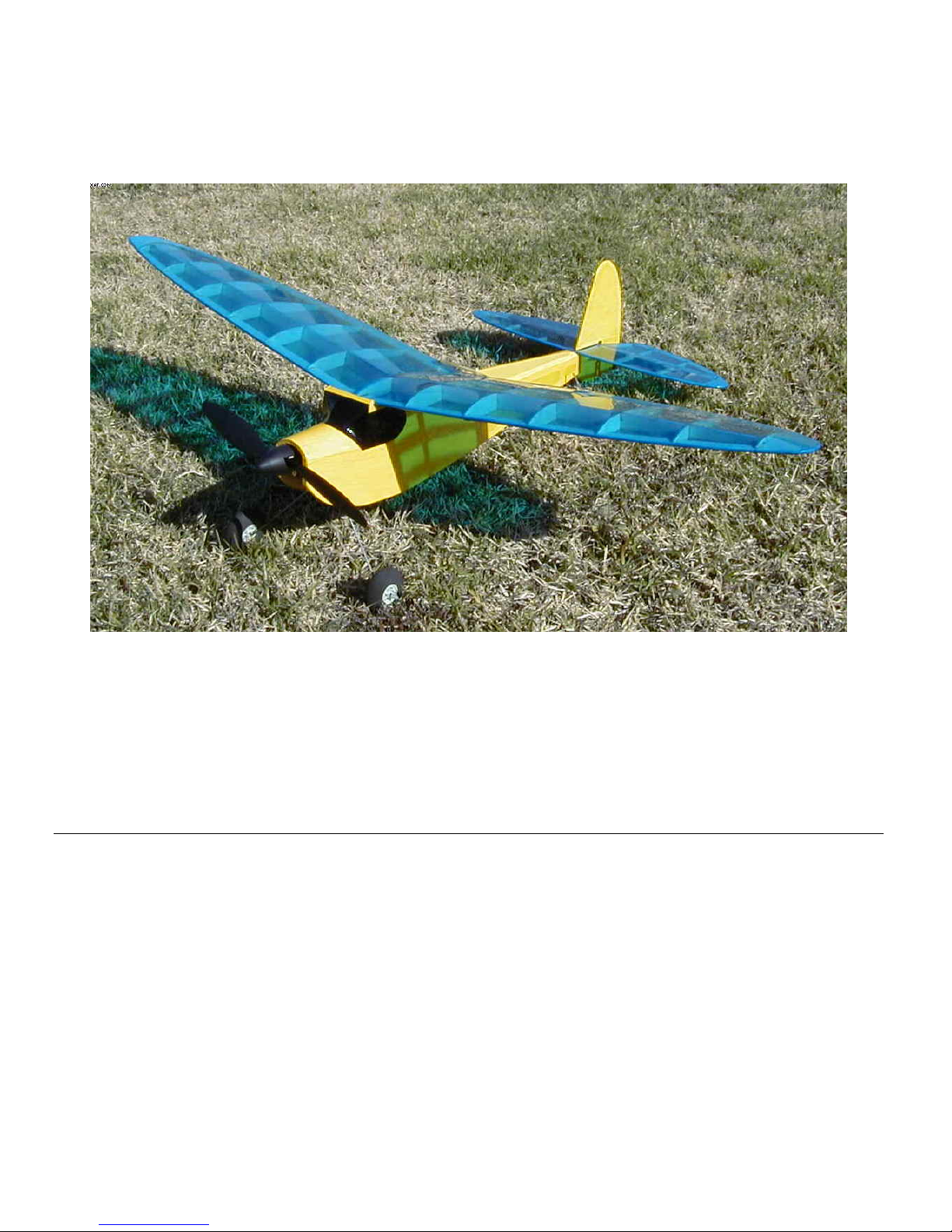
LoLo
A sporty parkflyer with an Old Timer flair!
Designed by: Tres Wright
Kitted by: Park Scale Models
http://www.ParkScaleModels.com/
Assembly Instructions
General Information
The laser cutting process leaves a slight discoloration or “burn” on the laser cut edges of the parts. The builder
can if desired sand the edges lightly to remove this. If a light colored covering (like white) is used, the “burn”
marks will show through the covering if they’re not removed.
Most parts will fall easily out of the laser cut sheets. If a part does not fall out, do not force it. Use a hobby
knife to trim along the balsa “tabs” that hold the part in until the part is freed.
The ribs, formers and small misc. parts are identified with engraved numbers. Major subgroups that are
grouped on a sheet together do not have individual engraved numbers on them. It is advisable to leave the
parts in the sheets until they’re needed to make identification easier.
Page 1 of 16

Where the instructions call for pinning parts, do not pin through the balsa. Place pins on either side of the
parts to hold them in place.
Abbreviations used in the instructions:
LC Laser Cut
TE Trailing Edge
LE Leading Edge
Tools and Supplies
The following basic items will be required to complete this kit:
- Thin and thick C/A glue
- Sandpaper
- “T” pins
- Hobby Knife (Exacto #11 blades recommended)
- Wax paper
- Metal straight edge
- Work surface capable of being pinned into (a ceiling tile works well)
- Wire cutters & pliers (for forming control wires)
- Small patches of Velcro
- Covering (SoLite recommended, otherwise known as Nelson LiteFILM)
- Covering iron
- Pencil
- Hinge tape (clear packing tape is recommended)
- Wheels (1-3/4” diameter Dubro wheels are shown on the drawing)
The following items are not required but are recommended:
- Hobby razor saw
- C/A accelerator
- 6” plastic cable ties (to hold landing gear in place)
2 1/8” thick laser cut balsa sheet
3 1/16” thick laser cut balsa sheet
1 1/64” thick laser cut light plywood sheet
1 1/8” hardwood dowel
1 1/8" Light Ply laser cut sheet
1 1/16” music wire for landing gear
Contents of Kit
Page 2 of 16
Construction Steps
***See addendum at the end of the instructions for changes to the assembly of the wing and
the brushless motor mount. Follow instructions except when modified by addendum.***
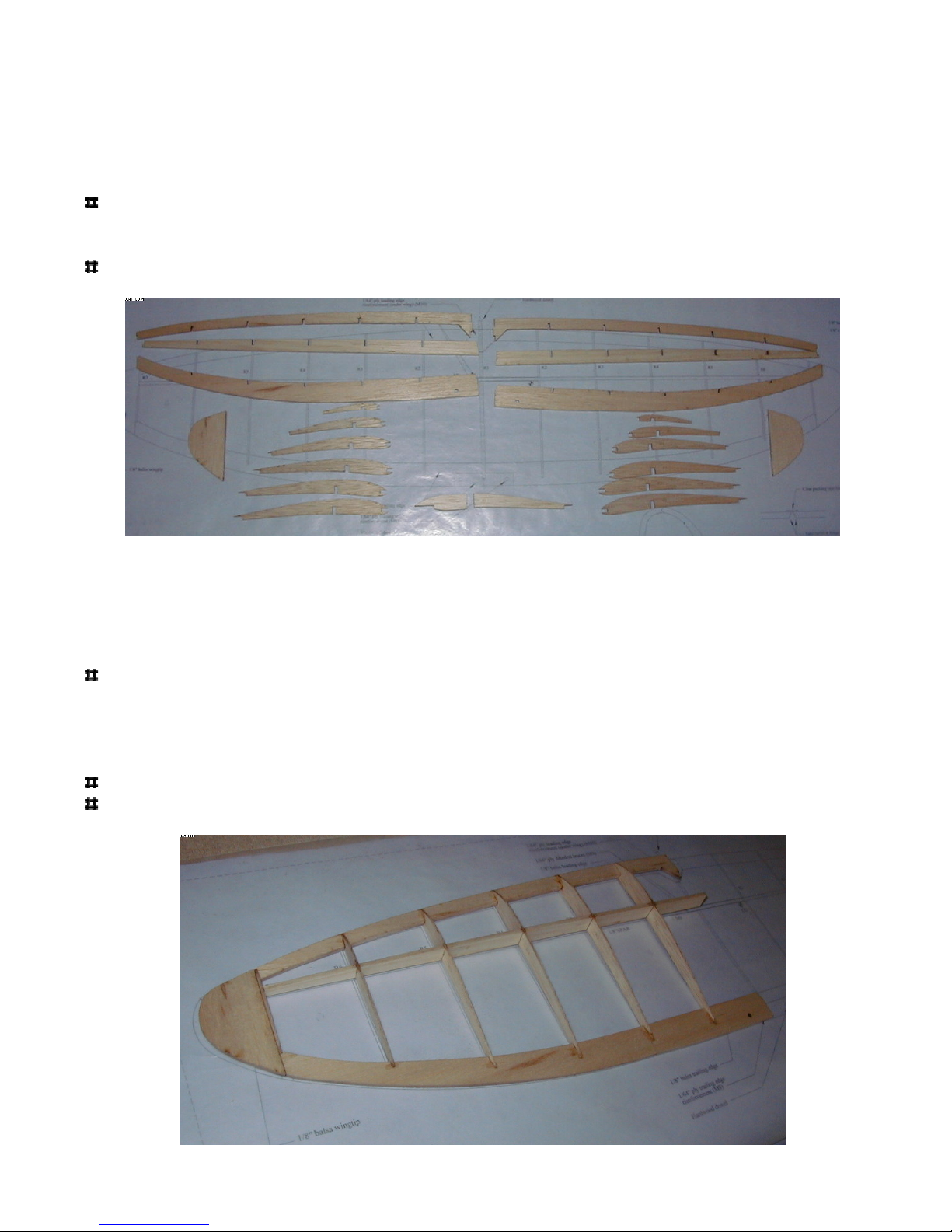
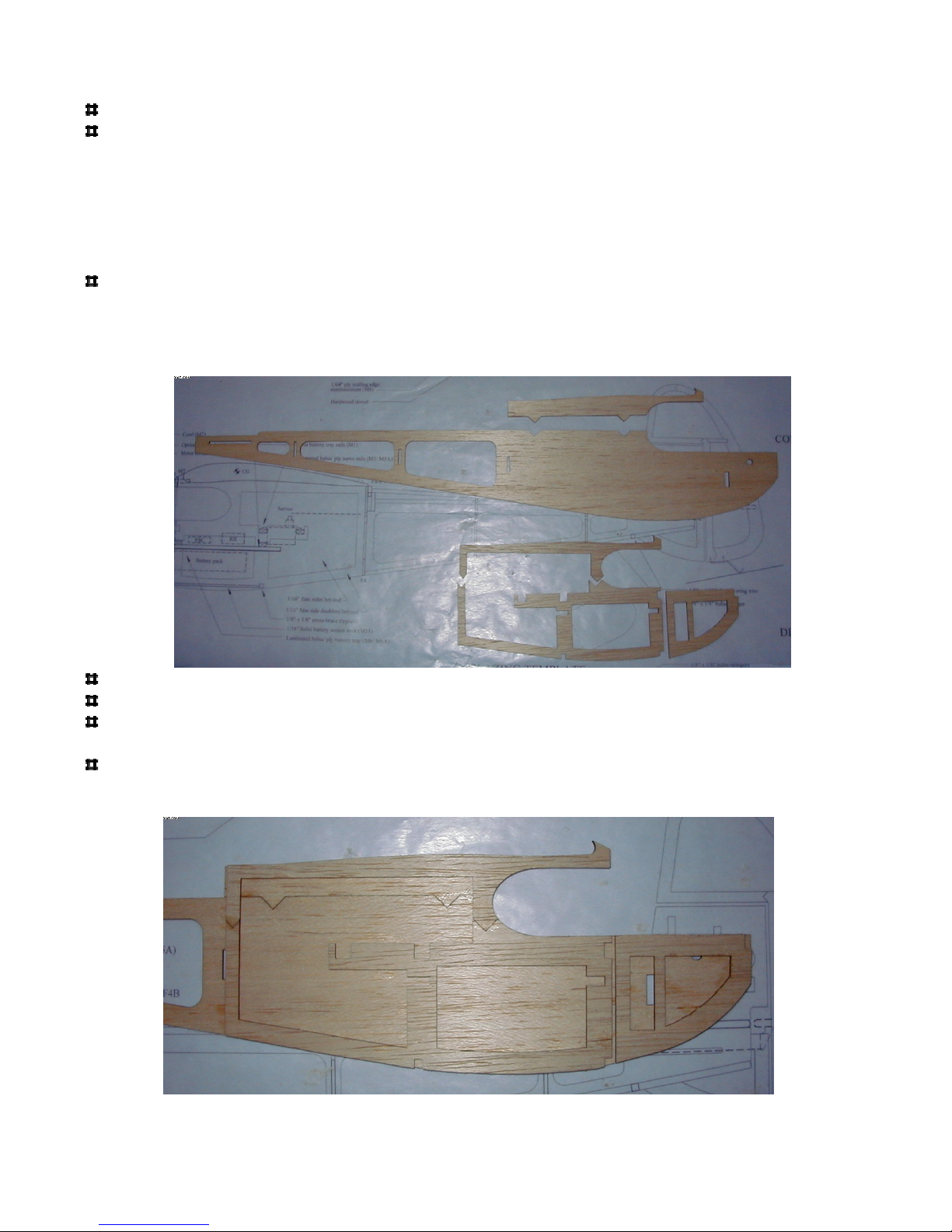
Remove all ribs, trailing edges (TE), leading edges (LE) and spar material from the laser cut (LC)
sheets. Group them into two sets for left and right.
*Note that due to the wing being undercambered, the spar will not rest on the work surface during
construction. Make sure the spar is properly seated in the ribs, it should be flush with the top and
bottom of each rib.
Begin with the left wing half:
Insert ribs R2 through R6 onto the wing spar and trailing edge. Insert the leading edge into the
slots at the front of the ribs. Align the assembly over the plan to make sure it is square and place a
drop of thin C/A at each part joint on the leading edge and trailing edge only. Lift the center spar
up so that it is flush with the tops of the ribs and glue it at each rib. Make sure the spar is fully
seated on the ribs!
Insert rib R7 into place and glue.
Hold the wingtip in place using the plan as a reference and glue it.
Page 3 of 16
Now build the right wing half. Note that the parts for each wing half are identical, take care not to
build two of the same side wing halves!
Insert ribs R2 through R6 onto the wing spar and trailing edge. Insert the leading edge into the
slots at the front of the ribs. Align the assembly over the plan to make sure it is square and place a
drop of thin C/A at each part joint on the leading edge and trailing edge only. Lift the center spar
up so that it is flush with the tops of the ribs and glue it at each rib. Make sure the spar is fully
seated on the ribs!
Insert rib R7 into place and glue.
Hold the wingtip in place using the plan as a reference and glue it.
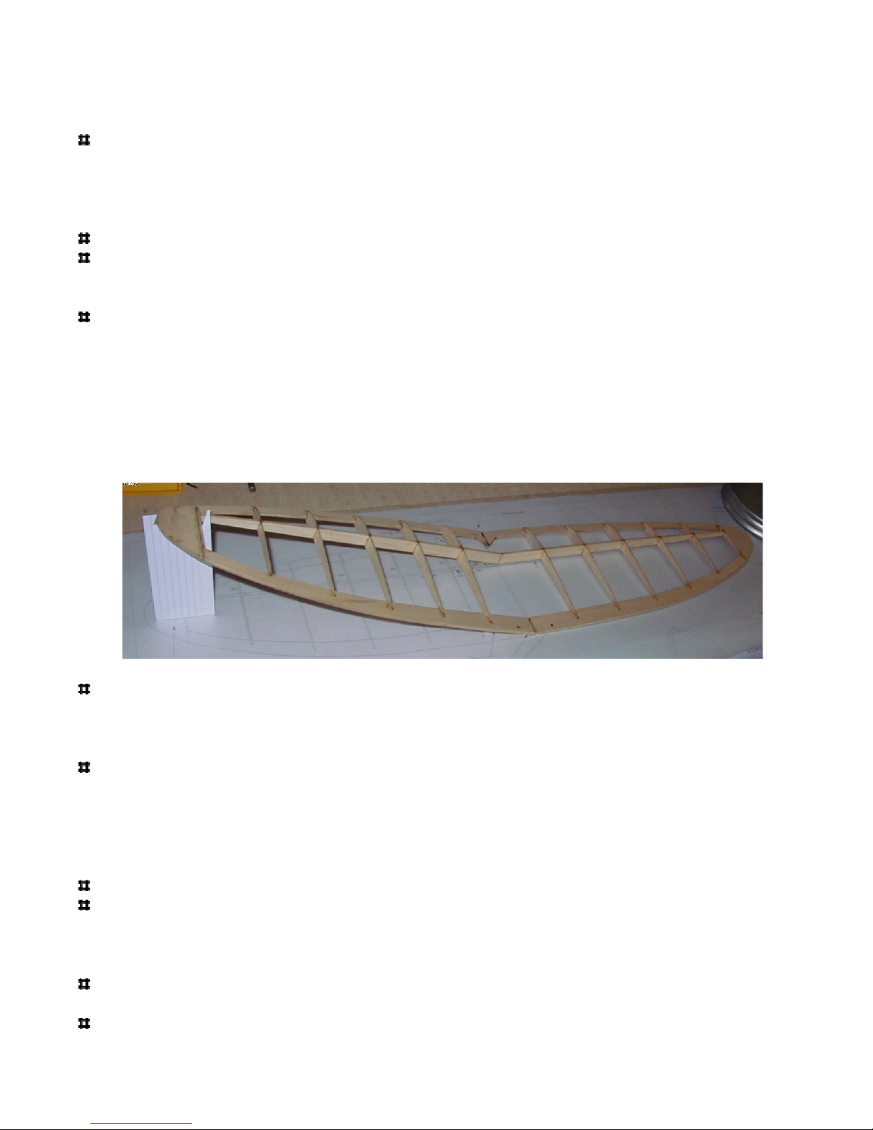
Join the wing halves together:
Lightly sand the leading edge and trailing edge joining surfaces until you get a tight fit at the
dihedral angle. Note that the spars need no sanding, use them as a reference to determine how well
the fit is. Sand the LE and TE until the spars fit tightly together. Once a tight fit is achieved, glue
all the joints with thin C/A. The dihedral angle will be determined by the spar joining. When one
wing half is flat on the work surface, the other wing half should be approximately 4-3/4” above the
surface. A “dihedral template” is provided on the plan, you may cut this shape out of stiff paper to
check and make sure the dihedral angle is correct. The template should fit under one wingtip while
the other wing is flat.
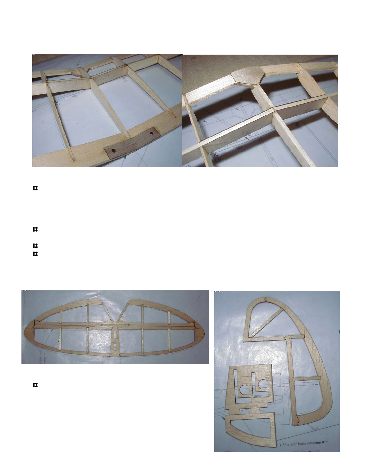
Install the 1/64” ply dihedral doublers (part M9) on each side of the spar. Glue into place.
Building tip: some of the plywood reinforcement parts have holes laser cut through them; these
holes can be used to glue the parts into place. Thin C/A can be placed in the hole and it will wick
between the parts.
Install the two R1 pieces into the LE and TE slots and align against the M9 doublers. It might be
necessary to slightly enlarge the slots in the LE and TE depending on how much sanding was done
when the wing halves were joined. Glue the R1 pieces into place.
Final sand the wing assembly (it is easiest to use a sanding block for this, or sandpaper wrapped
around a small block of wood):
Sand the leading edge and wingtips to a rounded profile.
Sand the top surface of the trailing edge to an angled profile that follows the lines of the ribs (it is
easiest to do this by laying the wing so that the trailing edge is on the edge of a table and then use a
sanding block to sand the angle, be careful not to damage the ribs). Round the bottom edge of the
trailing edge.
Glue the 1/64” ply reinforcement (part M8) onto the top of the trailing edge while keeping the
holes aligned.
Glue the 1/64” ply reinforcement (part M10) onto the bottom of the leading edge.
Page 4 of 16
The wing is now complete. There are two holes in the trailing edge and a hole in the center of the
leading edge for dowels. These will be installed later after the wing is covered.
Build the horizontal stab and elevator:
Remove all parts from the sheet labeled “Elevator/ Stab”. Align the parts over the plan view of the
tail. Make sure the horizontal trailing edge material is installed so that the notches align with the
leading edge notches (“LT” and “RT” is engraved into these parts, this indicates “left top” and
“right top”). Glue the parts together. Cut the remainder of the parts from the supplied 1/8” x 1/8”
balsa stock and glue into place.
Cut a 2” piece from the supplied 1/8” hardwood dowel stock and glue into the slot on the leading
edge of the elevator.
Remove the tail parts from the plan and sand all edges to a rounded profile.
The elevator will be hinged to the top surface of the stabilizer by taping it into place after the parts
are covered. In order to achieve proper surface movement, the mating edges must be sanded to a
bevel shape as shown on the drawing (refer to the Control Surface Detail). Sand the trailing edge
of the stabilizer and the leading edge of the elevator to a bevel as shown on the drawing.
Build the vertical stab and rudder:
Remove all parts from the sheet labeled “Rudder”.
Align the parts over the plan view of the rudder and
glue them together. Cut the remainder of the parts
from the supplied 1/8” x 1/8” balsa stock and glue
into place. The two vertical stab pieces are not glued
to anything until after the tail pieces and fuselage are
covered in later steps.
Page 5 of 16
Remove the rudder from the plan and sand all edges to a rounded profile.
The rudder will be hinged to the vertical stabilizer pieces by taping it into place after the parts are
covered. In order to achieve proper surface movement, the mating edges must be sanded to a bevel
shape as shown on the drawing (refer to the Control Surface Detail). Sand a bevel into one side of
the rudder and into the matching side of the two vertical stabilizer pieces as shown on the drawing.
Build the left fuselage side (note that the parts for each side are identical, take care to build
opposite sides!):
Remove the fuselage sides and fuselage doublers from the sheets. Note that there are two pieces to
each fuselage side and 3 pieces to each side doubler. The doublers can break next to the servo rail
cutouts, so handle with care. If they break, simply align them over the plan and lightly glue the
break. Once they are glued to the fuselage sides in the below steps they will be quite strong.
Glue the upper fuselage section to the lower section. The parts notch together.
Glue the upper doubler section to the lower section. The parts notch together.
Glue the doubler to the inside section of the fuselage, make sure all sides are aligned properly.
Reference the plan and photos for clarification.
Glue the nose doubler in place. Note that there is to be a gap between the nose doubler and fuse
doubler, this allows the nose to be angled inward during final assembly.
Page 6 of 16
Build the right fuselage side (note that the parts for each side are identical, take care to build
opposite sides!):
Glue the upper fuselage section to the lower section. The parts notch together.
Glue the upper doubler section to the lower section. The parts notch together.
Glue the doubler to the inside section of the fuselage, make sure all sides are aligned properly.
Reference the plan and photos for clarification.
Glue the nose doubler in place. Note that there is to be a gap between the nose doubler and fuse
doubler, this allows the nose to be angled inward during final assembly.
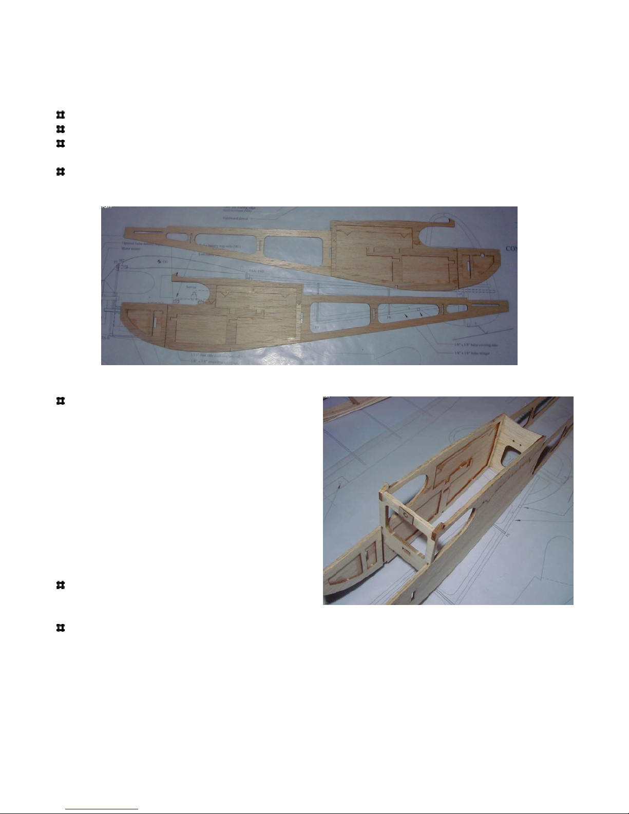
Assemble the fuselage:
Insert formers F3 (light ply) and F4 (balsa)
into the slots of one fuselage side. Refer
plan for locations. Note that F3 has “Front”
laser cut into one face, this face should face
the front of the plane because it will set the
thrust angle of the motor mount. F4 has
“Back” laser cut into one face, this face
should face the tail. Check to make sure the
formers are square to the fuselage side and
glue into place. Install the second fuselage
side on the formers, check to make sure the
sides are properly aligned and glue into
place.
Glue 1/64” ply reinforcement M7 to front of
F3. There are lines engraved into F3 for
alignment.
Insert former F5 into place, check fuselage alignment and glue F5.
Page 7 of 16
 Loading...