

Parksafe Automotive PS440, PS740, PS1040-16, PS1040-16W, PS1940-16 Installation Manual
...
AUTOMOTIVE
Parking Sensor Installation
& User Guide v2
Specications Subject To Change Without Notice

TABLE OF CONTENTS
FITTING 1
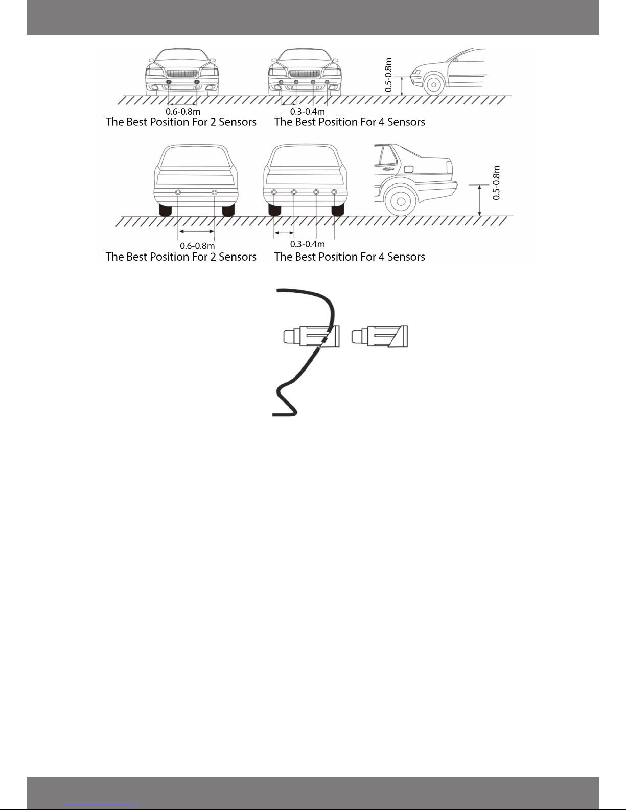
- Fitting position
- How to use collars
- Check rst
- Sensor tting
- Control box tting
- Buzzer tting
WIRING DIAGRAMS 2
- Front parking sensor wiring
- Rear parking sensor wiring
- Two sensor system
- Dip switch settings
WIRING CONNECTIONS 3
- Wire colours
PS9** SERIES FITTING GUIDE 4
DISPLAYS
- PS62
- PS64
- PS64FRONT
- Display error codes
CANBUS INTERFACES 6
- PSPK1
- PSPK4
- CANRUI programmer
TROUBLESHOOTING 7-8
- False beeps or constant tone
- System not working
- Power up beeps
- Cleaning sensors
- Checking a sensor is working
- Not detecting some objects
- Front parking sensors not activating on CANBUS system below 6mph
- CANRUI Engineers programming kit
USING YOUR PARKING SENSOR SYSTEM 9
- Rear system
- Front system
SENSOR ID 10
WARRANTY 12
DISCLAIMER 13
FITTING
Check First
Before drilling holes with the provided hole cutter check for the following.
1. Make sure no ller has been used on the bumper, this can cause install issues.
2. Make sure no crash bar is directly behind the hole you plan to drill and you have enough space behind
the cut hole for the sensor and cable so as not to over bend the cable or force the cable against any
metal.
Sensor Fitting
1. Use masking tape to protect the bumper and allow for easy marking of the sensor positions.
2. Cut the hole with the provided hole cutter letting the cutter do the work, do not put pressure on the
cutter as the centre drill could fail and cause damage to the bumper.
3. Remove any swarf from the hole and make sure the sensor ts okay neither being too tight or too
loose.
4. Locate the sensor in the up position, (there is a mark on the back of the sensor showing the up
position) and install into the bumper.
5. When securing cables do not crush with a cable tie or bend too tightly as this will eect the operation
of the sensors.
6. Leave some slack to allow for sensor removal if needed at a later date.
Control Box Fitting
Fix securely in a suitable location away from moisture allowing for access to the connectors. Ideally all
connectors should face down.
Buzzer Fitting
Fix securely in a suitable location away from moisture, ideally in a position where it is not covered for
maximum volume.
How To Use Collars
Page 1
WIRING
Page 2
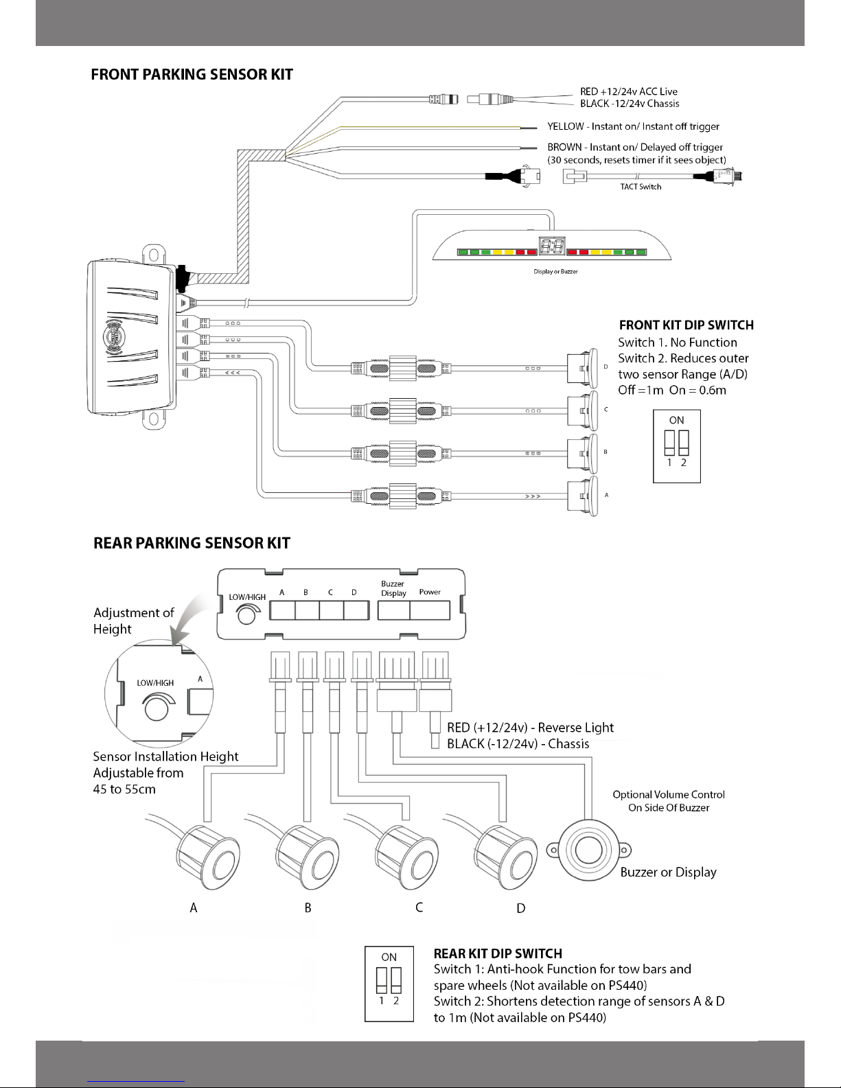
FRONT & REAR ADDITIONAL WIRING INFO
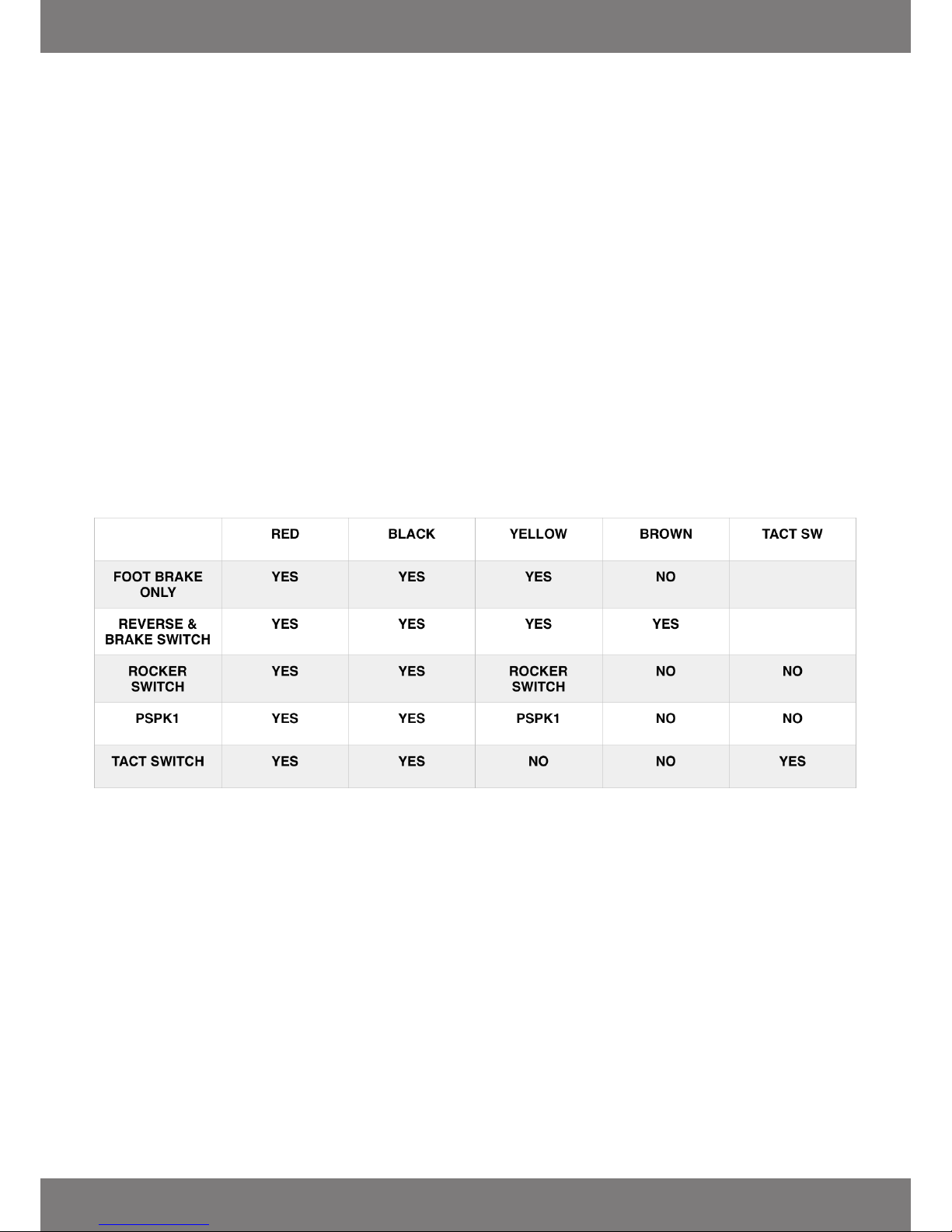
Wiring connections:
• Power Feed - Red to Ignition Live
• Power feed - Black to Chassis
• Foot brake - Use the yellow wire.
Sensors will come on when the foot brake is applied and go o when not applied. There is no hold on
delay. The yellow wire is also used for the PSPK1 (See Page 6) .
• Reverse Light - Use the brown wire.
When reverse is selected the sensors will arm and remain on for 15 seconds. If they do not detect
anything they will turn o. If they do detect they will remain on for another 15 seconds.
• Tact Switch - This is a timer switch.
Press green button for two seconds and the sensors will activate, hold for 5 seconds and they will
deactivate. If the sensors detect an object they will remain on, if no detection they will turn o after 30
seconds.
•Using your own switch.
Connect the yellow wire to a rocker switch, Switch on = Sensors on, Switch o = Sensors o.
• Trailers, Caravans and Bike racks
If you tow and don’t want the sensors activating when in reverse the simplest method is to t a rocker
switch in the boot and wire it between the reversing light and the 12 volt input of the parking sensor
control box.
• DISPLAYS (See page 5)
Front displays will only work on front sensors and rear displays will only work on rear displays. For display
orientation please check the manual.
• TWO SENSOR SYSTEMS WITH BUZZER
If you use only two sensor heads then you plug them into C and D.
Page 3
 Loading...