

Page 1
OPERATING
INSTRUCTIONS
12"
AND
PARTS
LIST
FOR
THICKNESS
PLANER
IM
PORT
to
secure
avoid unnecessary
We
suggest
valuable
THE
PARKS
Manufacturer.s
ANT:
papers.
WOODWORKING
This list
prompt
that
0/
Quality
is
valuable. It
service on
correspondence
you
keep
Woodworking
replacement
it
with our
filed away
MACHINE
Machines
will
enable
parts
factory.
wi·th
Since
you
and
other
COMPANY
1887
August
1,
1952
Page 2
Instructions
For
Operation
and
Maintenance
of
12
11
The PARKS THICKNESS PLANER
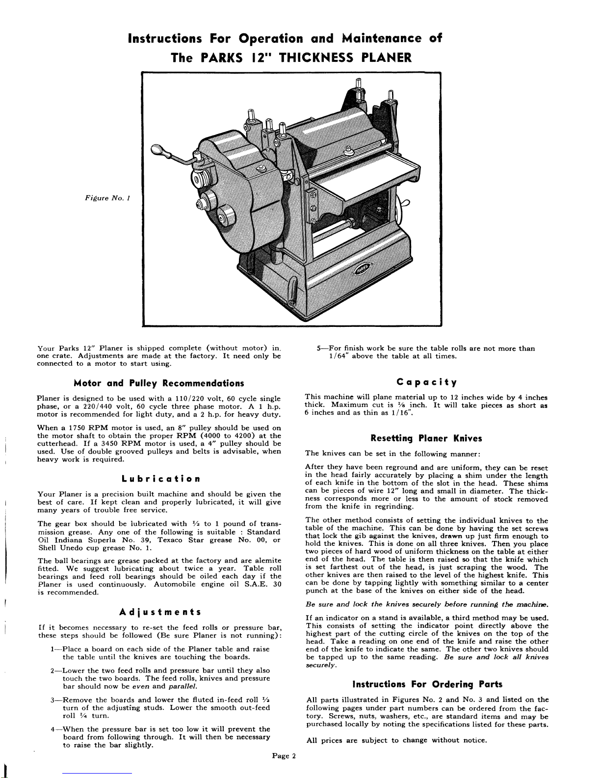
Figure
No.1
Your
Parks
12"
Planer
is
shipped
complete
(without
motor)
in.
one
crate.
Adjustments
are
made
at
the
factory.
It
need
only
be
connected
to a motor
to
start
using.
Motor
and
Pulley Reco·mmendations
Planer
is
designed
to
be
used
with a 110/220
volt,
60
cycle
single
phase,
or a 220/440
volt,
60
cycle
three
phase
motor.
A 1
h.p.
motor
is
recommended
for
light
duty,
and
a 2
h.p.
for
heavy
duty.
When a 1750
RPM
motor
is
used,
an
8"
pulley
should
be
used
on
the
motor
shaft
to
obtain
the
proper
RPM
(4000
to
4200)
at
the
cutterhead.
If a 3450
RPM
motor
is
used,
a
4"
pulley
should
be
used.
Use
of
double
grooved
pulleys
and
belts
is
advisable,
when
heavy
work
is
required.
Lubrication
Your
Planer
is a precision
built
machine
and
should
be
given
the
best
of
care.
If
kept
clean
and
properly
lubricated,
it
will
give
many
years
of
trouble
free
service.
The
gear
box
should
be
lubricated
with
:Yz
to 1 pound
of
trans-
mission
grease.
Anyone
of
the
following
is
suitable : Standard
Oil
Indiana
Superla
No.
39,
Texaco
Star
grease
No.
00,
or
Shell
Unedo
cup
grease
No.1.
The
ball
bearings
are
grease
packed
at
the
factory
and
are
alemi
te
fitted.
We
suggest
lubricating
about
twice a year.
Table
roll
bearings
and
feed
roll
bearings
should
be
oiled
each
day
if
the
Planer
is
used
continuously.
Automobile
engine
oil
S.A.E.
30
is
recommended.
Adiustments
If
it
becomes
necessary
to
re-set
the
feed
rolls
or
pressure
bar,
these
steps
should
be
followed
(Be
sure
Planer
is
not
running):
I-Place a board
on
each
side
of
the
Planer
table
and
raise
the
table
until
the
knives
are
touching
the
boards.
2-Lower
the
two
feed
rolls
and
pressure
bar
until
they
also
touch
the
two
boards.
The
feed
rolls,
knives
and
pressure
bar
should
now
be
even
and
paraIIel.
3-Remove
the
boards
and
lower
the
fluted
in-feed
roll
:Y;l
turn
of
the
adjusting
studs.
Lower
the
smooth
out-feed
roll
Y'4
turn.
4-When
the
pressure
bar
is
set
too
low
it
will
prevent
the
board
from
following
through.
It
will
then
be
necessary
to
raise
the
bar
slightly.
Page
2
5-For
finish
work
be
sure
the
table
rolls
are
not
more
than
1/64"
above
the
table
at
all
times.
Capacity
This
machine
will
plane
material
up
to
12
inches
wide
by
4
inches
thick.
Maximum
cut
is
1/
8
inch.
It
will
take
pieces
as
short
as
6
inches
and
as
thin
as
1/16".
Resetting
Planer
Knives
The
knives
can
be
set
in
the
following
manner:
After
they
have
been
reground
and
are
uniform,
they
can
be
reset
in
the
head
fairly
accurately
by
placing a shim
under
the
length
of
each
knife
in
the
bottom
of
the
slot
in
the
head.
These
shims
can
be
pieces
of
wire
12"
long
and
small
in
diameter.
The
thick-
ness
corresponds
more
or
less
to
the
amount
of
stock
removed
from
the
kni
fe
in
regrinding.
The
other
method
consists
of
setting
the
individual
knives
to
the
table
of
the
machine.
This
can
be
done
by
having
the
set
screws
that
lock
the
gib
against
the
knives,
drawn
up
just
firm
enough
to
hold
the
knives.
This
is
done
on
all
three
knives.
Then
you
place
two
pieces
of
hard
wood
of
uniform
thickness
on
the
table
at
either
end
of
the
head.
The
table
is
then
raised
so
that
the
knife
which
is
set
farthest
out
of
the
head,
is
just
scraping
the
wood.
The
other
knives
are
then
raised
to
the
level
of
the
highest
knife.
This
can
be
done
by
tapping
lightly
with
something
similar
to a center
punch
at
the
base
of
the
knives
on
either
side
of
the
head.
Be
sure
and
lock
the
knives
securely
before
running
t'!re
machine.
If
an
indicator
on a stand
is
available, a third
method
may
be
used.
This
consists
of
setting
the
indicator
point
directly
above
the
highest
part
of
the
cutting
circle
of
the
knives
on
the
top
of
the
head.
Take a reading
on
one
end
of
the
knife
and
raise
the
other
end
of
the
knife
to
indicate
the
same.
The
other
two
knives
should
be
tapped
up
to
the
same
reading.
Be
sure
and
lock
all
knives
securely.
Instructions
For
Ordering
Parts
All
parts
illustrated
in
Figures
No.2
and
No.3
and
listed
on
the
following
pages
under
part
numbers
can
be
ordered
from
the
fac-
tory.
Screws,
nuts,
washers,
etc.,
are
standard
items
and
may
be
purchased
locally
by
noting
the
specifications
listed
for
these
parts.
All
prices
are
subject
to
change
without
notice.
Page 3

I
,
I
I
I
\
"
...
"
A-34
A-29
J
Figure
No.2
'repaid
Prepaid
Prepaid
Part
No.
Name
of
Part
selling
prhe
Part
No.
Name of
Part
selling price
Part
No.
Name of
Part
selling
price
each
each
each
A-I
Gear
Box
(casting
only)
_
21.64
A-13
Lower
gear
shaft
bearing
A-26
Head
ball
bearing
No.
A-2
Shaft
collar
%"
bore
(3
¥2"
bore
.
._
3.20
3204
(2
req.)
_...
_. __. ..
__
4.00
req.)
. .
.88
A-14
88
tooth
gear,
plain
hub
.
6.40
A-27
Head
shaft
spacer
.._...
.94
A-3
Hollow
head
set
screw
3.18"
A-IS
Short
gear
shaft
_
2.20
A-28
12"
Head
with
shaft__.__. _
59.98
x
3.18"
-
%-16
thread
_
.34
A-16
Gear
shaft
bear'g
V2"
bore
3.20
A-4
12
tooth
sprocket
(2
req.)
2.66
A-17
20
tooth
gear
(3
req.)
_
2.20
A-29
Slotted
head
set
screw
fi"
A-S
Shaft
spacer .__
... ._.. _
x -&" -
ftI-18
thread.._.
.20
.94
A-I8
Gear
shaft
bearing
3/
4
"
A-6
88
tooth
gear,
slotted
hub
6.40
bore
(2
req.).
_
3.20
A-30
Fluted
feed
roll
... ....._
16.00
A-7
Throw
out
sleeve
bearing
A-19
Long
gear
shaft
_
2.58
A-31
Hollow
head
set
screw
V2"
1Vs"
bore
.. ...
1.98
A-20
128
tooth
gear
.. .__.
9.38
(used
on
head)
.
._
.34
A-8
9.48
4.74
Throw
out
sleeve
.. .
A-21
Gear
box
cover __. _
A-32
12"
Chip
breaker
(3
req.)
2.S8
A-9
Eccentric
bracket
studs
(2
A-22
Gear
box
cover
studs
(2
req.)
_
req.)
.. ..
_. __. . _
A-33
12"
High
speed
knives
.80
.42
(setof3)
. _
15.00
A -34
Complete
roller
chain
.. _
3.10
A-IO
Eccentric
bracket
. .
__
1.68
A-23
Smooth
feed
roll
. .
._
14.80
A-II
Throw
out
handle
. .
3.10
A-24
Felt
washer
. ._.. .
.20
A-12
Throw
out
eccentric
.
...
3.70
A··25
Head
shaft
sleeve
1.00
A-35
Connecting
link
for
chain
.56
Page
3
Page 4

A-3
A5
~61
Figure
No.3
Prepaid
Prepaid
Prepaid
Part
No.
Name
of
Part
selling
price
Part
No.
Name
of
Part
selling
price
Part
No.
Name of
Part
selling
price
each
each
each
A-36
Pressure
bar
_
A-49
5/
8
"
hex
nut
1"
long
3h-16
8.50
A-59
Left
side
casting
-.
42.22
thread
.66
A-37
Hood
stud
(2
req.)
_
.34
A-60
Rieht
side
casting
41.
78
A-50
Spring
collar
(6
req.)________
.64
A-38
Shaving
hood
_
13.30
A-61
Base
----------------
28.24
A-51
Compression
spring
(6
A-39
Lock
nut
for
hood
_
.34
A-62
Elevating
shaft
.__________
2.42
req.)
.50
A-40
Adjusting
stud
for
hood
_
.80
A-63
Shaft
collar
5/
8
"
(4
req.)_.__
.86
A-52
Roll
bearing
stud
(4
req.)
1.46
A-41
Table
roller
(2
req.)
_
4.82
A-64
Bevel
gear
LI02
(4
req.)._
2.38
A-53
Pressure
bar
stud
(2
req.)
1.46
A-42
Table
roll
bearing
(4
req.)
1.42
A-54
Smooth
feed
roll
bearing
A-65
Elevating
screw
(2
req.-
2.20
A-43
Table
._-------_----------------__--
58.32
(2
req.-specify r or
1)__
1.48
specify
right
or
left)
A-44
Table
gib
(2
req.)--------------
2.20
A-55
Stud
collar
(2
req.)____________
.50
A-66
Column
tie
rod
(2
req.)-___
2.64
A-45
Lock
nut
for
table
gib
_
.50
A-56
Fluted
feed
roll
bearing
(2
A-67
Hand
wheel
and
handle.___
6.70
req-specify r or
1)________
2.20
A-68
Depth
indicator
.. . .42
A-46
Lock
nut
stud
--------------------
.34
A-47
Table
roller
adjusting
stud
.80
A-57
Bearing
cap
studs
(2
req.)
.80
A-69
Depth
scale __._.
..
._
.34
A-58
Bearing
cap
5.32
A-48
Lock
nut
for
table
roller
_
.34
A-70
I/4"
oiler
(4
req.).__.....
._
.34
(speci
fy
right
or
left)
The
following
parts shown on figures 2 and 3
are
stan~ard
and can
be
purchased
locally
A-71
Half
moon
key
l6"------------
.20
A-74
3/8" x 11"
jam
nut
/6"
A-76
Hex
nuts
7"2"
x
-,fu"
X 0/8"
A-72
.22
3" V pulley
3/
4
"
bore__________
1.44
thick
3h-16
thread
.50
I/2-13
thread
_
A-73
3At"
x
ti"
jam
nut
-rlJ"
A-7S
Hex
head
bolts
7"2"
x 1
3
,4"
A-77
Alemite
fitting
. _
.34
thick
%-16
thread
---.--
..._ .50 I/2-13
thread
._________________
.22
Page
4
 Loading...