

Page 1
Page 2
Introduction
Introduction
This gas cooker has been designed and manufactured to all the
necessary British Standards. This cooker complies with European
Council Directive 90/396/EEC. It also carries the C.E. mark.
cooker properly before you use it for the first time.
booklet thoroughly before you use the cooker. Keep the booklet in a
safe place so that anyone who uses the cooker can read it. Pass the
booklet on with the cooker if you give or sell it to someone else.
L Y R I C 5 0 G X
It is important that you understand how to use and care for the
We have written this booklet with your safety in mind. Read the
For your safety
This cooker is designed for domestic use to cook food. You
must not use it for any other purpose. It is not designed for
commercial use.
Keep children, babies and toddlers away from the cooker at all
times.
The installation instructions that came with the cooker tell you
how and where it can be fitted. If the cooker is already installed
you must make sure that all instructions have been followed. If
you are in any doubt ask a registered person. More details on
installation on page 28.
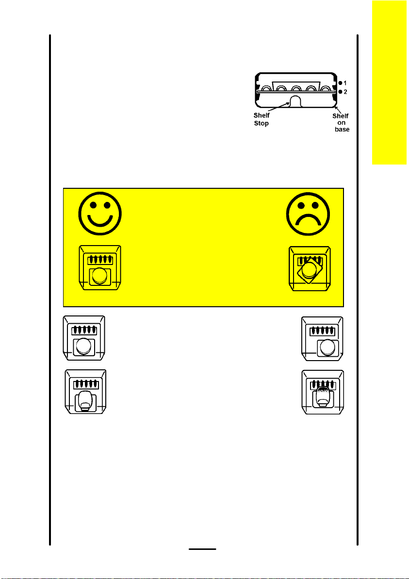
We have included several drawings to show the right and wrong way
of doing things.
The right way will have a smiling face by it.
A sad face shows something is wrong.
Important: Make sure you remove the sales stickers before you use
this cooker.
2
Page 3
L Y R I C 5 0 G X
Contents
Contents
Lighting the cooker 4
The grill 7
The hotplate 9
The ovens 12
Oven cooking chart - main oven 15
- top oven 18
Slow cooking 21
Care and cleaning 23
Installing the cooker 28
General information 30
What is wrong and why? 32
Servicing 33
Installation Instructions 34
Technical Data 35
Safety requirements/ventillation 36
Location of appliance/installation 37
Page
Testing 39
3
Page 4
L Y R I C 5 0 G X
Lighting the cooker
The system works by means of a battery. Details on how to replace the
battery are given on page 30.
Hotplate and Grill
Lighting the cooker
To light:
1 Push in the control knob and turn it to the large flame symbol
(highest setting), and press the ignition button immediately. When
the burner has lit release the button.
For your safety
Never cover the grill pan or grid with foil as this can lead to
grill fires.
Warning: If the ignition button is not pressed immediately a build up of
gas may cause the flame to spread.
4
Page 5
L Y R I C 5 0 G X
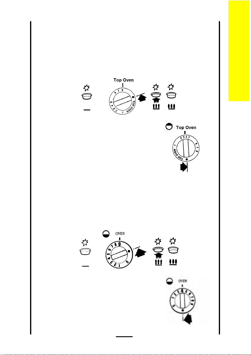
Top oven
To light:
1 Open the oven door.
2 Push in the control knob and turn it to the left to gas mark 8, and
press the ignition button immediately. When the burner has lit
release the button. There will only be small flames at first.
3 Now turn the control knob to the gas
mark you want.
4 Wait until the burner is showing large
flames.
5 Close the oven door.
Main oven
Lighting the cooker
To light:
1 Open the oven door.
2 Push in the control knob and turn it to gas mark 9, and press the
ignition button immediately. When the burner has lit release the
button. There will only be small flames at first.
3 Now turn the control knob to the gas
mark you want.
4 Wait until the burner is showing large
flames.
5 Close the oven door.
5
Page 6
Li
h
i
h
k
er
L Y R I C 5 0 G X
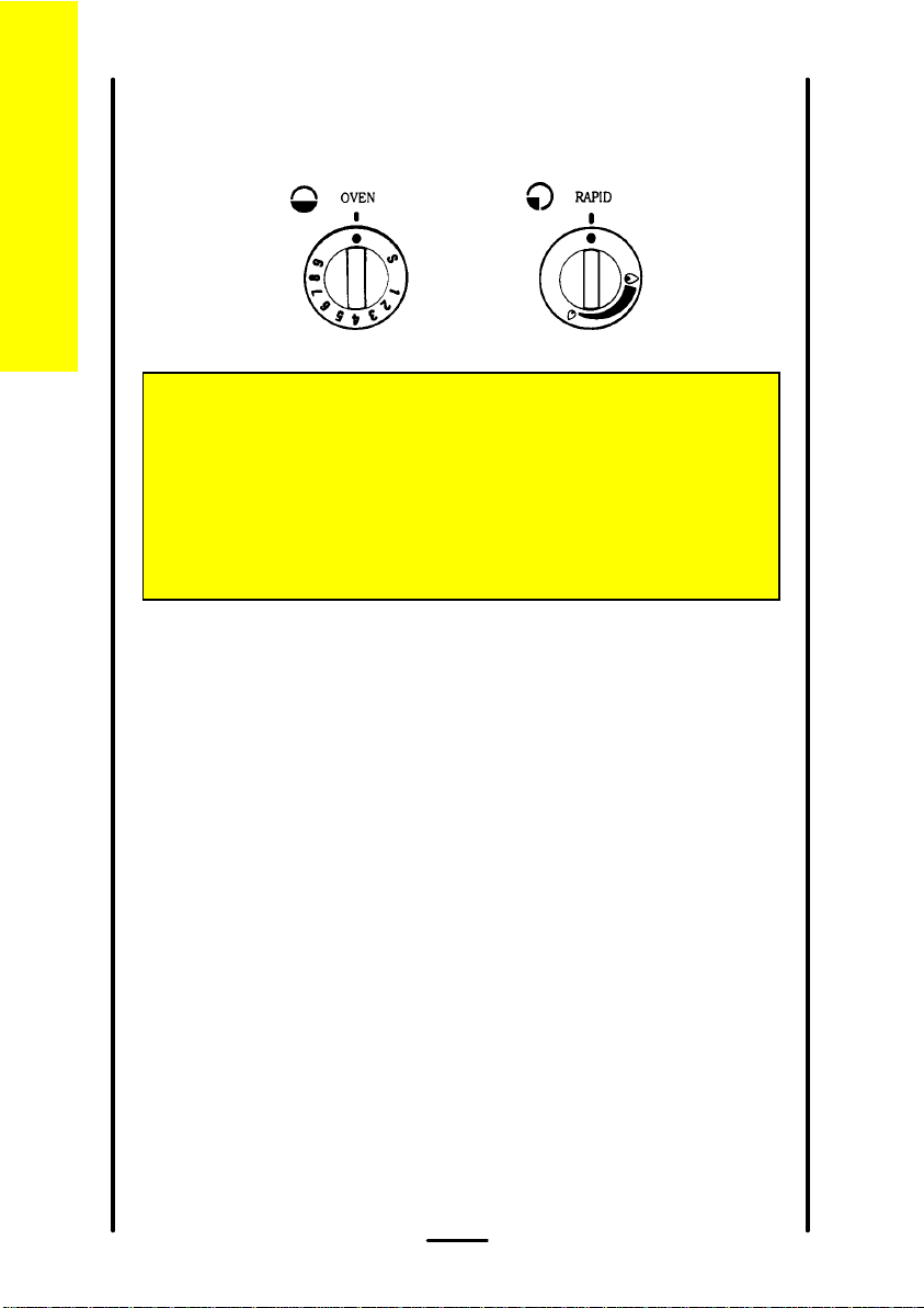
To turn off any burner
e coo
ng t
t
g
1 Push in the control knob and turn it to the off position. This is shown
by a large dot.
For your safety
When you are lighting any burner check that it has lit before
you leave the cooker.
When you are turning off a burner, do not leave the cooker
until the flame has gone out.
6
Page 7
The grill
L Y R I C 5 0 G X
The grill is a high-speed grill. The instructions below tell you how to vary
the heat setting and how to change the height of the trivet to suit the
food you are cooking. You should remember to turn the food regularly.
You should not use the grill to keep food warm as it will continue to
cook the food.
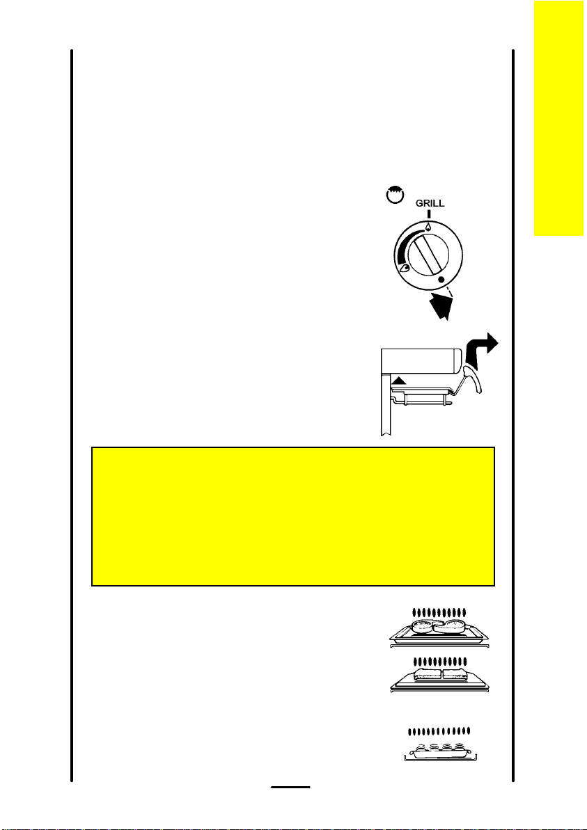
Heat control
The grill control has two heat settings.
The control knob turns to the left from 'OFF'
to 'HIGH' and then to 'LOW'. Use the high
setting for fast cooking such as toast. Use the
low setting to cook thicker food such as chicken
after you have browned it on the high setting.
Grill pan
The pan is designed so that you can pull it
forward but it will stay supported. To remove the
pan push it back as far as possible and lift it off.
Replace it in reverse order.
For your safety
After replacing the pan, pull it out to make sure it has fitted back
properly.
Never cover the grill pan or grid with foil as this can lead to grill
fires.
The grill
Cooking positions
Most food should be cooked on the trivet in
the grill pan. You can turn the trivet over to suit
different thicknesses of food.
You can place some dishes straight on to
the grill shelf. This is useful when you are
browning the top of food such as cauliflower
cheese.
7
Page 8
Preheating
L Y R I C 5 0 G X
The grill
You don't usually need to preheat the grill. You may wish to preheat it for
a couple of minutes when you are cooking steak or browning food.
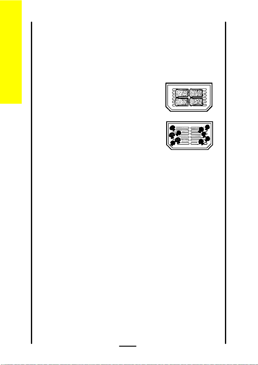
Putting food on the trivet
Place food such as toast, tea-cakes and muffins
towards the centre of the trivet.
Place food which needs a gentle heat, such as
tomatoes and mushrooms towards the edge of
the trivet.
Arrange meat, meat products and fish to suit
their thicknesses and how you like them
cooked.
Warming plates
When using the cooker you can use the shelf below the grill pan to
warm two plates. Do not put plates on the shelf when the grill burner is
turned on and the grill pan is not in place. The heat from the burner will
damage the plates.
8
Page 9
L Y R I C 5 0 G X
The hotplate
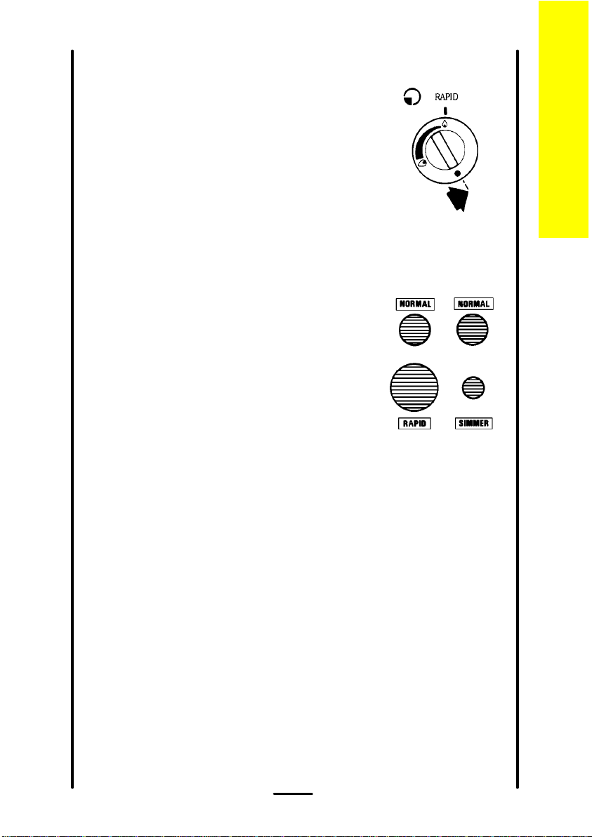
Heat control
The hotplate control knobs turn to the left from
'OFF' to 'HIGH' and then to 'LOW'. You can
adjust the heat by turning the control between
the highest and lowest settings. These are
shown as a large and a small flame symbol.
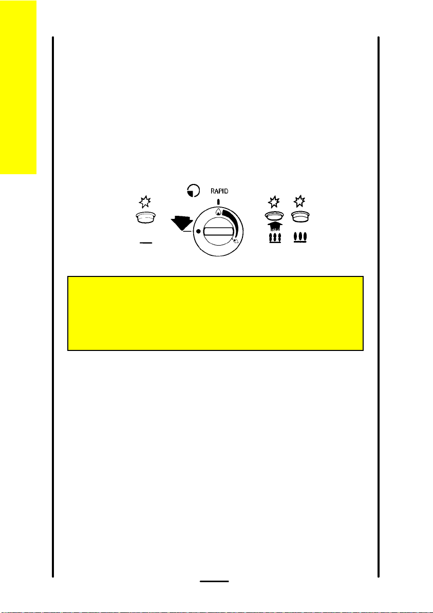
Burner sizes
The hotplate has three burner sizes to suit
different types of cooking:
Largest burner (Rapid) - use a large pan for
food such as chips.
Medium burners (Normal) - use for everyday
cooking.
The hotplate
Small burner (Simmer) - use for simmering food
such as soups and stews.
The largest pan which you should use on any burner is 230mm (9").
The base of the smallest pan should not measure less than 100mm (4").
9
Page 10
Th
h
l
ate
otp
e
L Y R I C 5 0 G X
For your safety
1
Take care to avoid burns and scalds when you
are reaching across the hotplate.
Use pans with flat bases. They are more stable
than pans which are warped.
Do not use pans with very heavy handles which
cause the pan to tip.
Put pans on the centre of the burners.
Position pan handles so they cannot be
accidentally knocked.
Take extra care when you are deep fat frying. Do
not cover the pan with a lid.
Do not leave a pan unattended. If the pan
catches fire, leave it where it is and turn off all
controls.
Place a damp cloth or a fitting lid over the pan to
smother the flames.
Never put water on the fire.
Leave the pan to cool for 30 minutes.
7
7
If you are using a Wok we recommend it has a flat
base as it will stand stable on the pan supports. If
you use a round based Wok with a collar support,
the collar must be of the open wire work type. A
closed collar will affect the performance of the
burner. Before you use the Wok make sure that
the collar is stable on the pan supports. Always
follow the instructions that come with the Wok.
10
Page 11
L Y R I C 5 0 G X
Helpful hints
The hotplate
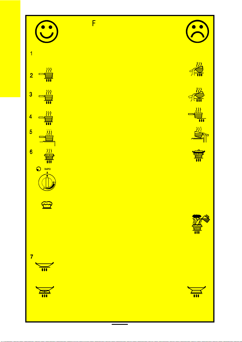
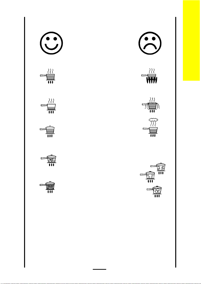
1
2 Only heat the amount of liquid you
3 Cover pans with a lid whenever
4 Try cooking more than one
5 Cut vegetables into smaller pieces.
Keep flames under the base of
pans. If the flames lick round the
sides of the pans you are wasting
gas.
need. Do not overfill pans.
possible. The food will heat up
more quickly and there will be less
steam in the kitchen.
vegetable in the same pan, for
example potatoes and carrots.
This way they will cook more
quickly.
6 A pressure cooker will save time
and energy.
11
Page 12
The ovens
Before you use the oven you should wipe it
out with a damp cloth to remove any dust.
The ovens
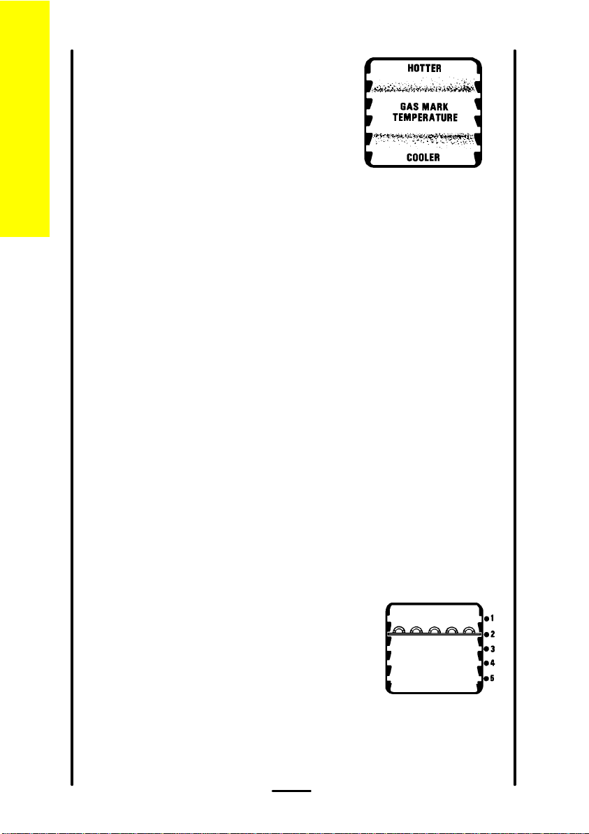
Heat zones
Main Oven - There are zones of heat
within the oven. The temperature in the
middle is the gas mark you have chosen. The top of the oven is slightly
hotter and the lower shelf slightly cooler. The base of the oven is quite
a lot cooler. You can make use of these heat zones when you are
cooking foods requiring different temperatures all at the same time.
cakes or biscuits, swap the trays around during cooking. Or you could
remove the top tray when the food is cooked and move the lower tray to
the higher shelf to finish cooking.
Top Oven - You can only cook on one shelf at a time. You should turn
food round during the cooking time.
Preheating
You do not need to preheat the main or top oven for casseroling and so
on.
such as Yorkshire puddings, soufflés and yeast mixtures.
instructions on the packaging. When you are using the top oven to cook
or reheat convenience food you should preheat the oven to gas mark 8.
20 minutes.
L Y R I C 5 0 G X
If you are cooking more than one tray of similar items, for example
Preheat the ovens for baking or when you are cooking sensitive food
When you are cooking or reheating frozen or chilled food read the
When you need to preheat the oven, we recommend you do so for
Oven shelves
The shelf in the top oven is different from the
shelves in the main oven. You can distinguish
the top oven shelf from the main oven shelves
because it has a metal plate attached to it. The
shelves provided for the main oven should only
be used in the main oven. Similarly, only use
the top oven shelf in the top oven.
You can slot the oven shelves into any of
five positions in the main oven and any of two
positions in the top oven.
12
Page 13
L Y R I C 5 0 G X
Shelf positions are counted from the top
downwards.
Most top oven cooking should be carried out
using the shelf provided in shelf position 2.
However, when cooking a small joint or a deep
cake you can use the top oven shelf on the
base of the top oven to allow enough air to
circulate around the food. There is a stop at the
back of the top oven. You should not try and
push the shelf back beyond this stop.
Baking trays and dishes
For your safety
Never place cooking dishes, trays
and so on over the oven burners.
This will damage the cooker as
well as the ovenware and possibly
the floor covering underneath the
cooker.
The ovens
Leave a gap of 13mm (½") between all
dishes and the sides of the oven so the
heat can circulate properly.
Do not push dishes too far back as food
will burn if it overhangs the burner flames.
For the best results from the main oven we recommend that you use
a baking tray which is 310mm (12") square. If you use a tray or tin
which is larger than this, you may need to turn it around during cooking.
The size of tray which should be used in the second oven should
measure no more than 310mm x 230mm (12" x 9"). Position the longest
side parallel with the door.
Place single dishes on the centre of the shelf. You may need to turn
large items around during cooking.
13
Page 14

Condensation
Condensation may form on the cooker. This is quite normal and nothing
The ovens
to worry about. The condensation forms when heat and moisture are
present, for example during cooking. Whenever possible try to make
sure that food which contains a lot of moisture for example casseroles
are covered. If you do notice any condensation, wipe it up straight
away.
Roasting
For best results we recommend open roasting using minimal fat or oil to
prevent splashing.
It is not necessary to cover meat or poultry or wrap food in foil when
roasting as this restricts the circulation of heat and will lead to extended
cooktimes.
If you are using a roasting bag or cover chicken breast with foil, be
prepared to allow an extra 10 - 15 minutes for each 1/2kg (1lb).
When cooking large items such as turkeys, the use of foil may be
required to prevent the breast becoming dry before the rest of the bird is
fully cooked.
L Y R I C 5 0 G X
14
Page 15

L Y R I C 5 0 G X
30 mins. per ½kg (1 lb) and 30 mins.
25 mins. per ½kg (1 lb) and 25 mins.
20 mins. per ½kg (1 lb) and 30 mins.
25 mins. per ½kg (1 lb) and 25 mins.
30 mins. per ½kg (1 lb) and 30 mins.
30 mins. per ½kg (1 lb) and 30 mins.
35 mins. per ½kg (1 lb) and 35 mins.
Oven cooking chart
Approximate
cooking time
Shelf
position
Gas
mark
Medium:
Well Done:
Well Done:
Lamb 5 4 Medium:
Well Done:
Thoroughly thaw frozen joints before cooking them
Pork and Veal 5 4 Medium:
Food
Oven cooking chart - Main oven
These instructions are for cooking in the oven after it has been pre-heated for 20 minutes.
If you are cooking more than one tray of similar items, for example cakes or biscuits, swap the trays around during cooking or you
can take the top tray out of the oven when the food is cooked and move the lower tray to the higher shelf to finish cooking.
Always leave at least one shelf position between shelves to allow heat to circulate.
The recommended shelf positions give the best results.
Put the dishes in the centre of the shelf.
You can change the gas marks and cooking times to suit your own tastes.
It is important to check that food is piping hot before serving.
If you are using both ovens at the same time you may need to adjust the cooking times.
Roasting meat: Beef 5 4 Rare:
15
Page 16

L Y R I C 5 0 G X
Oven cooking chart
Approximate
cooking time
Shelf
position
25 - 35 mins.
15 - 25 mins.
4 - 5 hours.
2
2
44432 & 4
2¼ - 2½ hours.
2½ - 2¾ hours.
1 hour.
15 - 25 mins.
10 - 20 mins.
2 & 4
20 - 30 mins.
20 - 35 mins.
2 & 4
2 & 4
Gas
mark
5 4 20 mins. per ½kg (1 lb) and 20 mins.
4 4 25 mins. per ½kg (1 lb) and 25 mins.
4 4 or 5 15 mins. per ½kg (1 lb) and 15 mins.
5 4 25 mins. per ½kg (1 lb).
Turkey below 4.5kg (10lbs)
over 4.5kg (10lbs)
Duck and duckling
Food
Poultry: Chicken
Cook as above but calculate weight including stuffing.
Thoroughly thaw frozen joints before cooking them.
Stuffed poultry
7
7
- individual
The times given above are for open roasting in a preheated oven. If you cover the food with foil or a lid allow an extra 10 - 15 minutes for
each ½kg (1lb).
Yorkshire pudding - large
22245
Rich fruit, 180mm (7")
205mm (8")
Cakes: Christmas Cake (8")
16
7
4
4
Madeira, 180mm (7")
Small cakes
Scones
Victoria sandwich
180mm (7")
205mm (8")
Page 17

To help pastry brown on the underside
Approximate
cooking time
25 - 35 mins.
Shelf
position
2
L Y R I C 5 0 G X
cook on a metal plate, or if plates are flat
and have no rim underneath, place on
baking tray.
25 - 35 mins.
15 - 25 mins.
2
2& 4
2 hrs. approx.
45 - 60 mins.
50 - 60 mins.
30 - 40 mins.
3
4
4
3
30 - 40 mins.
10 - 20 mins.
3
2
Oven cooking chart
Gas
mark
6
6
5
Fruit pie (shortcrust)
Mince pies (flan pastry)
Pastries: Plate tart (shortcrust)
Food
2
4
3
8 *
8 *
8 *
Baked sponge pudding
Baked custard
Puddings: Milk puddings
0.90kg (2lb loaves)
Rolls and buns
Yeast mixtures: Bread 0.45kg (1lb loaves)
17
When baking bread cook for 10 minutes at Gas Mark 8 then reduce to Gas Mark 6 for the remaining cook time.
Note: You must soak dried beans then boil them in an open pan for 15 minutes before you add them to any dish.
Page 18

L Y R I C 5 0 G X
Oven cooking chart
20 mins. per ½kg (1 lb) and 30 mins.
Approximate
Rare:
cooking time
30 mins. per ½kg (1 lb) and 30 mins.
25 mins. per ½kg (1 lb) and 25 mins.
25 mins. per ½kg (1 lb) and 25 mins.
30 mins. per ½kg (1 lb) and 30 mins.
Medium:
Well Done:
30 mins. per ½kg (1 lb) and 30 mins.
Medium:
Well Done:
35 mins. per ½kg (1 lb) and 35 mins.
Medium:
Well Done:
Shelf
position
Gas
mark
Oven cooking chart - Top oven
These instructions are for cooking in the oven after it has been pre-heated for 20 minutes.
The recommended shelf positions give the best results.
Put the dishes centrally on the shelf.
You can change the gas marks and cooking times to suit your own tastes.
It is important to check that food is piping hot before serving.
If you are using both ovens at the same time you may need to adjust the cooking times.
Food
oven base
Roasting meat: Beef 5 Shelf on
oven base
Lamb 5 Shelf on
oven base
Pork and Veal 5 Shelf on
Thoroughly thaw frozen joints before cooking them.
18
Page 19

L Y R I C 5 0 G X
Approximate
cooking time
20 mins. per ½kg (1 lb) and 20 mins.
25 mins. per ½kg (1 lb).
Shelf
position
Shelf on
oven base
Shelf on
oven base
3 -4 hours.
2 - 2½ hours.
1 hour.
Shelf
on
oven base22
15 - 25 mins.
8 - 12 mins.
20 - 30 mins.
2
Oven cooking chart
To help pastry brown on the underside
cook on a metal plate, or if plates are flat
and have no rim underneath, place on
baking tray.
25 - 35 mins.
25 - 35 mins.
15 - 25 mins.
222
Gas
mark
Food
5
5
Duck and duckling
Poultry: Chicken
2 2457
Thoroughly thaw frozen joints before cooking them.
Stuffed poultry Cook as above but calculate weight including stuffing.
The times given above are for open roasting in a preheated oven. If you cover the food with foil or a lid allow an extra 10 - 15 minutes for
each ½kg (1lb).
Rich fruit, 180mm (7")
Madeira, 180mm (7")
Small cakes
Yorkshire pudding - individual 7 2 20 - 30 mins.
Cakes: Christmas cake (7")
4
665
Scones
Victoria sandwich
180mm (7")
Pastries: Plate tart (shortcrust)
Fruit pie (shortcrust)
Mince pies (flan Pastry)
19
Page 20

L Y R I C 5 0 G X
Oven cooking chart
2 hrs. approx.
45 - 60 mins.
2
2
50 - 60 mins.
2
Approximate
cooking time
Shelf
position
Gas
2
mark
Puddings: Milk pudding
Food
3
3
Baked sponge pudding
Baked custard
Note: You must soak dried beans then boil them in an open pan for 15 minutes before you add them to any dish.
20
Page 21

L Y R I C 5 0 G X
Slow cooking
Please note: There is no slow cook on the top oven.
The slow cook setting gives a very low heat in the oven. It is
particularly useful when you are cooking soups, stews and casseroles
because the long slow cooking will make cheaper, tougher cuts of meat
more tender.
You need to cook food at gas mark 6 for 30 minutes before you turn
the oven down to the slow cook setting. This makes sure that the
temperature of the food gets hot enough to start the food cooking.
Some foods such as pastry and biscuits are not suitable for slow
cooking because the temperature is too low.
Cover all food during cooking to prevent it from drying out. You can
uncover food for the last half hour if it is normally served golden brown.
Slow cooking
Food preparation - slow cooking
Joints of meat and poultry
l
Do not cook meat joints over 2.7kg (6lb).
l
Do not cook poultry over 2 kg (4lb 8oz).
l
Cook on the middle shelf of the oven or above.
l
Cook stuffing separately.
l
Cook for at least 6 hours.
l
Only cook joints of pork if you can make sure, by using a meat
thermometer, that the temperature inside the joint is at least 88°C.
l
For good air circulation always stand joints on a rack in the roasting
tin or casserole.
l
Thaw all frozen meat and poultry before you cook it.
l
Prime cuts of meat do not benefit from slow cooking.
l
Cut off unwanted fat and skin unless it is browned first.
l
Cook for 30 minutes at gas mark 6, then reduce to the slow cook
setting.
21
Page 22

Soups, casseroles and stews
l
Do not cook casseroles over 3 kg (6lb).
l
Bring to the boil on the hotplate then cook on slow cook.
l
Cook in the middle of the oven or above.
Slow cooking
Vegetables
l
Cut into small pieces.
l
Dried beans must be pre-soaked then boiled in an open pan for 15
minutes before adding to any dish.
l
Place vegetables under meat in casseroles.
l
Cook for 30 minutes at gas mark 6, then reduce to the slow cook
setting.
Milk puddings
l
Cover the cereal with boiling water and leave it to stand for 30
minutes.
l
Drain and make the pudding in the usual way.
l
Cook for 30 minutes at gas mark 6, then reduce to the slow cook
setting.
General points for slow cooking
Frozen foods
Thaw thoroughly before cooking.
L Y R I C 5 0 G X
Thickening
Toss meat in flour for casseroles. Blend cornflour with water and add it
at the end of cooking.
Flavouring
Flavours are held in the food because there is little evaporation. Adjust
flavouring at the end of the cooking time.
Liquid
Use slightly less liquid as there is little evaporation during cooking.
Milk and milk products, for example cream
Add these towards the end of cooking to prevent them from curdling.
Reheating
Cool left over food quickly and then put it in the fridge. Do
not reheat food using the slow cook setting. Reheat food in the usual
way or in a microwave.
Only reheat food once.
22
Page 23

L Y R I C 5 0 G X
Care and cleaning
For your safety
For hygiene and safety reasons you must keep this gas cooker
clean. A build up of fat or other foodstuff could cause a fire.
Try to mop up spills and splashes as soon as they happen.
But be careful as parts of the appliance will be hot.
Do not use any polishes, caustic cleaners, abrasives, washing soda
or soap powder except those recommended in this booklet.
Please note: If we recommend
you use hot soapy water we mean
hot water with washing up liquid in it
and not any other cleaning product.
If you own a dishwasher please
read the operating instructions for
the machine before you wash any
part of your cooker.
Clean your cooker regularly using a cloth that has been wrung out in
hot soapy water. Rinse and polish it dry using a soft cloth.
When you remove parts of your cooker for cleaning do not plunge
them into water whilst they are very hot as this may damage the finish of
the parts.
Care and cleaning
The hotplate
Clean the hotplate top using a mild abrasive such as 'Jif'. Take care not
to damage the spark electrodes. If the spark electrodes are damaged
the burners will not light.
You can remove the pan supports, burner caps and burner crowns
to clean them. Again take care not to damage the spark electrodes.
If any food spills do occur during cooking you can place the pan on
another burner to finish cooking. Then you can remove the dirty parts
and clean them before the spill 'burns on'.
23
Page 24

C
d
l
i
ng
ean
c
are an
L Y R I C 5 0 G X
You can wash the removable parts in very hot soapy water. You may
use mild abrasives. Make sure that the electrode and the hole and slots
in the crown are not blocked with food or cleaning materials.
Clean the burner crowns by soaking them in very hot soapy water.
You can remove any stubborn stains by scouring with a soap filled pad
such as 'Brillo'. If you look after the burner crowns in this way they will
stay reasonably clean. However the surface will dull with time.
Aluminium based saucepans can leave shiny metal marks on the
pan supports. Clean the pan supports regularly to remove the marks
using a mild abrasive like 'Jif' with a soft scourer. For more stubborn
marks you can use a soap filled pad such as 'Brillo'.
After cleaning the cooker parts, dry them
thoroughly before you put them back.
When replacing hotplate burner parts
1. Crown to body (Do not try to force the
crown on to the body). Make sure that the
hole in the crown is over the electrode.
Check that the two longer location pegs
sit in the slots in the body. When the
crown is in this position let it fall freely on
to the body. Check that the crown can be
moved slightly from side, to side.
2. Cap to crown
Place cap centrally on the top of crown
(enamel side up). Move sideways and
front to back to check the cap is properly
fitted.
3. Check for ignition
If a burner will not light then you need to check the crown and cap
positions.
The grill
Clean the area around the grill frequently using hot soapy water.
After use you can soak the pan for a few
minutes and then clean it using mild
abrasives or a soap filled pad such as
'Brillo'.
Clean the shelf using hot soapy water. Mild abrasives can be used if
necessary. If the grill shelf is removed it must be replaced the right way
up. The outer wires must be curved upwards.
24
Page 25

L Y R I C 5 0 G X
The top oven
Clean the oven and shelf frequently using hot soapy water. Mild
abrasives can be used if necessary. The heat in the oven will change
the colour of the metal plate on the shelf. You must not remove the solid
plate from the shelf. You can soak the shelf for a few minutes in hot
soapy water to make cleaning easier.
The main oven
The top, sides and back of your oven are coated in a special material
which helps to keep itself clean.
Follow these simple rules to maintain the appearance of the special
finish.
Do not overfill dishes or they will boil
over.
Do not put dishes too high in the
oven. If you do they may stick to the
oven roof.
Care and cleaning
Cover your roasting tins with foil.
This will prevent fat splashing.
Use a roasting tin which is just large
enough for the meat and potatoes.
This will help to reduce fat
splashing.
Dry any vegetables that you are
going to roast. If they are wet there
will be more fat splashing.
6
Follow the oven cleaning cycle
regularly.
25
Page 26

Oven cleaning cycle
C
Please note: The oven cleaning cycle can only be used in the main
oven.
You need to follow the cycle to keep the inside of the main oven in
good condition. The type of cooking you do will affect how often you
are and cleaning
need to follow the cycle.
If you do a lot of roasting and very little other baking you should
follow the cleaning cycle once a week. If you do very little roasting you
will only need to follow the cleaning cycle every 2-3 weeks.
To carry out a cleaning cycle:
1. Remove the oven shelves.
2. Set the oven to mark 5 for at
least 30 minutes.
3. Turn the temperature up to
mark 7 for 2 hours or until the
oven is presentably clean.
Some staining will remain.
L Y R I C 5 0 G X
Do not use any cleaning agents
or scrapers on the inside of the
oven. Do not wash the special
finish.
General
Clean the base of the oven, the oven shelves and the oven door while
they are still slightly warm. This way you can easily remove any
splashes and spills. Wipe the base with a cloth that has been wrung
out in hot soapy water. You may use mild abrasives.
26
Page 27

L Y R I C 5 0 G X
Cleaning between the outer and inner glass
doors
You can remove the glass from both oven doors if you need to.
Note: For top oven door it is important not to open the door when the
glass is removed because the door is lighter and it will spring shut.
To remove the outer glass
1 Open the oven door so you can get at the two cross head screws on
the top of the oven door.
Note: Open top oven door slightly to access screws.
2 Loosen these two screws using a pozidrive screwdriver .
3 You should hold the door glass securely in place with one hand,
whilst removing the screws completely, with the other hand. If you do
not do this, the door glass could fall forward.
4 Using both hands, gently tilt the top of the door glass towards you.
Lift it slightly to disengage the locators at the bottom of the door.
Care and cleaning
5 Clean the outer and inner glass using hot soapy water and mild
abrasives such as 'Jif'. DO NOT try to clean the aluminium foil which
is inside the door. The foil is there to help keep the door cool, if it is
damaged it will not work.
6 Replace the glass by holding it in both hands and gently placing the
locators into the holes of the brackets at the bottom of the door. Push
the top of the glass towards the oven door, and make sure the screw
location holes line up.
7 Hold the glass in place with one hand and replace the cross head
screws into the location holes, with the other hand. Give the screws
one turn to make sure the glass is held in place.
8 Tighten the screws using a pozidrive screwdriver. Close the door.
27
Page 28

I
t
ll
ti
on
a
a
ns
L Y R I C 5 0 G X
Installing the cooker
For your safety
This cooker must be installed and serviced by a competent
person as stated in the Gas Safety (Installation & Use)
regulations current editions.
It is important that the cooker is suitable for your gas supply.
Your installer should check the data badge.
Ensure that a stability bracket is fitted.
Location
For your safety
The use of a gas cooking appliance results in the production
of heat and moisture in the room in which it is installed.
Ensure that the kitchen is well ventilated: keep natural
ventilation holes open or install a mechanical ventilation
device (mechanical extractor hood).
Prolonged intensive use of the appliance may call for
additional ventilation, for example opening of a window, or
more effective ventilation, for example increasing the level of
mechanical ventilation where present.
28
Page 29

L Y R I C 5 0 G X
Positioning
The diagram shows how close to the cooker cupboards, shelves,
curtains and so on can be fitted. Refer to the diagram and carefully read
the instructions to make sure your cooker is fitted safely. If you are in
doubt your installer will give you advice.
l
Do not fit any materials which may catch fire for example wood or
curtains behind the cooker.
l
Base units which are higher than the hotplate must be 100mm away.
l
We recommend that cabinets fitted next to or above the cooker meet
British Standards. Your installer will give you advice if you are not
sure.
Installation
All dimensions in mm
Cooker dimensions
Height to hotplate: 902mm - 920mm
(adjusted by four screw feet)
Width: 498mm
Depth: 603mm (to front of door panel)
29
Page 30

General information
G
For your safety
Do not block any of the cooker vents.
Never line any part of the cooker with aluminium foil.
eneral information
Do not let items which can catch fire or electric mains leads
such as kettle flexes trail over any part of the cooker.
Moving your cooker
You may damage some soft or badly fitted floor coverings when you
move the cooker. The floor covering under the cooker should be
securely fixed so it does not ruck up when you move the cooker across
it. Alternatively you could remove the floor covering.
To move the cooker open the grill door. Raise the cooker off its front
feet by lifting from inside the grill. Pull the cooker forward. When you
replace the cooker push it back to the stop and make sure there is the
same gap at each rear corner.
The battery
L Y R I C 5 0 G X
The battery for the ignition will
usually last for many months. If the
ignition system doesn't work you
probably need to replace the
battery.
The battery is at the base of the
cooker on the left-hand side of the
front.
When you need to replace the
battery, open the main oven door,
lift up the battery holder lid and
replace the battery as shown in the
diagram. The battery you need is
AA size.
When you fit the new battery, make sure the positive end (marked with a
+ sign) is next to the (+) sign on the battery holder. Close the lid of the
battery holder.
You can light the burners with a match until you have time to change
the battery.
30
Page 31

L Y R I C 5 0 G X
Reversing the main oven door
You can turn the oven door so that it opens on the other side. Your
supplier can arrange this.
General information
31
Page 32

What is wrong and why?
We strongly recommend that you carry out the following checks on your
cooker before calling a Service Engineer.
Problem
The oven, grill or hotplate will not light.
Check
l
If you cannot hear any sparking or if the sparking is slow when you
press the ignition button it may not be strong enough to light the
What is wrong and why?
cooker. You will probably need to replace the battery. For
instructions on how to do this see page 30. You can light the
burners with a match until you have time to change the battery.
l
Check that there is not a problem with your gas supply. You can do
this by making sure that other gas appliances such as your central
heating or gas fire are working.
l
If only the hotplate burners will not light, make sure that the burner
parts have been replaced correctly. See instructions on page 24.
Problem
Food is cooking too quickly or too slowly.
Check
l
Check that you are using the recommended gas marks and shelf
positions. See pages 15 - 20. Be prepared to adjust the gas mark
up or down to achieve the results you want.
Problem
The ovens are not cooking evenly.
Check
l
Check that the cooker is installed properly and is level.
l
Check that you are using the recommended temperatures and shelf
positions.
l
If you are using a tin or tray which is larger than the one we
recommend, be prepared to turn it round during cooking.
l
If you are cooking a large item be prepared to turn it round during
cooking.
l
To suit your own tastes you may prefer to turn some foods round
when cooking in the top oven.
Problem
Having difficulty cleaning any part of the cooker.
Check
l
Check that you are following the instructions for care and cleaning
(see page 23).
L Y R I C 5 0 G X
32
Page 33

L Y R I C 5 0 G X
Servicing
For your safety
Maintenance work must only be done by a competent person. Do
not try to repair the cooker yourself. This could be dangerous. It
is dangerous to alter or modify the product in any way.
We recommend that your cooker has an annual gas safety
check carried out by our approved service organisation.
Before you call a service engineer check through the 'What is wrong
and why?' information on page 32. If you still feel there is a problem you
should contact Parkinson Cowan on 08705 929929. Your call will be
routed to the Service Centre covering your postcode area.
Parkinson Cowan will arrange for the cooker to be serviced. Customers
in Ireland should telephone (10) 4565666.
You can get service and spares from Parkinson Cowan. If you don't
use manufacturers original spares the normal product approval of the
cooker may not be valid.
When you report a problem try to describe the nature of the fault.
Always give your cookers full name and serial number which you can
see when the door is opened.
Make a note of this information in this space:
Servicing
Name:
Serial Number:
The Gas Consumers' Council
The Gas Consumers' Council (GCC) is an independent organisation
which protects the interests of gas users. If you need advice, you will
find the telephone number in your local telephone directory under Gas.
33
Page 34

INSTALLATION INSTRUCTIONS
Serial number on
front frame. Data
badge on top rear
of panel
For your safety
Natural Gas and L.P. Gas versions of this appliance are available.
Check that this model is suitable for the type of supply available.
In the interest of safety this appliance must be installed and/or
serviced by a competent person, as stated in the Gas Safety
(Installation and Use) Regulations Current Editions.
34
Page 35

TECHNICAL DATA
DIMENSIONS
Overall 1462mm (nominal) 498mm 600mm
Height to hotplate 907mm nominal -
Space for fixing at hotplate level 2mm minimum 600mm
Space for fixing above hotplate level 100mm each side
Minimum space above grill 500mm
Minimum distance from rear wall 20mm
Weight of appliance 64.0kg
Height Width Depth
(from elbow
to front of door panel)
see important note 'Location of the Appliance' (see Page 37).
clearance Nominal
of appliance
CONNECTIONS
Gas Rear left hand side of appliance at hotplate level
Electric None
Rc½ (½" B.S.P. female)
IGNITION
Spark Generator APCO 7BG6893
Battery 1.5 volt AA size
GRILL
Heat Input 3.3kW (11263 Btu/h) 3.55kW (255g/h)
Injector Marking
Natural Gas L.P. Gas
138 95
35
Page 36

HOTPLATE
Natural Gas
Heat Input 1.0kW 2.0kW 2.0kW 2.8kW
Injector Marking 079 104 104 130
Heat Input 1.0kW 2.0kW 2.0kW 2.7kW
Injector Marking 51 72 72 83
MAIN OVEN
Heat Input 2.4kW (8189 Btu/h) 2.4kW (172.4g/h)
Injector Marking 108 78
Flame Supervision Device Diamond 'H' GSD 100/28 Diamond 'H' GSD 100-30
Thermostat Diamond 'H' 1100126/B2 Diamond 'H' 1100127/B2
Thermostat By-pass Marking 69 78
R.H.F. R.H.R. L.H.R. L.H.F
(3412 Btu/h) (6824 Btu/h) (6824 Btu/h) (9554 Btu/h)
L. P. Gas
R.H.F. R.H.R. L.H.R. L.H.F.
(71.8g/h) (143.7 g/h) (143.7 g/h) (194 g/h)
Natural Gas L P. Gas
TOP OVEN Natural Gas L.P.Gas
Heat Input 1.8kW (6142 Btu/h) 2.4kW (172.4 g/h)
Injector Marking 095 78
Flame Supervision Device Diamond 'H' GSD 100/44 Diamond 'H' GSD 100/46
Thermostat Diamond 'H' GSD 1100-112/B2 Diamond 'H' GSD 1100-99/B2
Thermostat By-Pass 73 79
GENERAL
Ignition H.T. Spark H.T. Spark
Spark Gap 3-4mm 3-4mm
IMPORTANT - SAFETY REQUIREMENTS
This appliance must be installed in accordance with the Gas Safety (Installation and Use) Regulations
Current Editions. Detailed recommendations are contained in the following British Standard Codes of Practice
- BS.6172, BS.5440: Part 2 and BS.6891. All British Standards must be 'Current Editions'.
PROVISION FOR VENTILATION
This appliance is not connected to a combustion products evacuation device. It shall be installed and
connected in accordance with the current installation regulations. Particular attention shall be given to the
relevant requirements regarding ventilation.
The room containing the appliance should have an air supply in accordance with BS. 5440: Part 2 Current
Edition. All rooms require an openable window or equivalent and some rooms will require a permanent vent
as well. For room volumes up to 5m³ an air vent of 100cm² is required: for room volumes between 5m³ and
10m³ an air vent of 50cm² is required. If the room has a door that opens directly to the outside, no air vent is
required. For room volumes that exceed 11m³ no air vent is required. If there are other fuel burning
appliances in the same room, BS.5440: Part 2 Current Edition should be consulted to determine the requisite
air vent requirements.
Prolonged intensive use of the appliance may call for additional ventilation, for example opening a window, or
more effective ventilation, for example increasing the level of mechanical ventilation where present.
36
Page 37

LOCATION OF APPLIANCE
This appliance must not be installed in a bed-sitting room of volume less than 20m³ or in a bathroom or
shower room. It is essential that the appliance is positioned as stated below. The appliance must be a
minimum of 20mm from the rear wall (note that this dimension is provided by the inlet elbow). Shelves, wall
cabinets and cooker hoods must not be fitted closer than 500mm to the top of the grill canopy or within
100mm of the sides of the grill. Curtains must not be fitted immediately behind the appliance or within 200mm
of the sides of the grill. If fitted next to or between two base units a minimum space of 1mm must be left
between the units and the sides of the appliance. The hotplate must be set to a minimum of 7mm above the
adjacent units (note that the levelling feet fitted to the appliance will achieve a nominal height to hotplate level
of 907mm -5+13mm). Base units not meeting the above conditions must be a minimum of 100mm away from
the hotplate. L.P.G. cookers MUST NOT be installed below ground level, i.e in a basement, or aboard any
boat, yacht or other vessel.
INSTALLATION
1. PARTS REQUIRED
The loose hotplate parts are packed in the polystyrene fitment on the top
of the hotplate. The grill pan, grill pan handle, fixing screws and
splashplate fixing screws can be found in the furniture pack which is
located in the bottom compartment. The grill pan requires assembly
before use (see Fig. 1).
2. GRILL ASSEMBLY
The two splashplate screws should be screwed into the back of the
appliance about halfway in (see Fig. 1a.) Engage the keyhole slots in the
splashback behind the two screws taking care not to trap the H.T. wire
(see Fig. 1b).
Tighten 6 off splashplate screws (see Fig.1c).
Connect the grill supply union at the back of the appliance and pull the
grill H.T. lead through the opening in the splashplate and connect on to
the spark generator.
Fig.1
Grill Pan Handle Assembly:-
Assemble grill pan (see Fig.1)
and secure four screws and
washers provided.
Fig.1a
Fig.1c
Fig.1b
37
Page 38

3. LEVELLING THE APPLIANCE
Adjustable levelling feet at the front and rear are provided on the base of the appliance.
Adjustment to suit floor conditions is obtained by rotating in or out the hexagonal feet from the underside of
the appliance.
A spirit level should be placed on one of the oven shelves to confirm that the appliance is correctly levelled.
4. FITTING THE STABILITY BRACKET
It is recommended that if the appliance is to be installed with a flexible supply pipe a stability bracket
(SK.4729.A) is fitted and is available from your supplier (see Important Safety Requirements, Page 36).
These instructions should be read in conjunction with the leaflet packed with the stability bracket.
1. Place the appliance in its intended position and level appliance.
2. Mark off 250mm from the left hand side of the appliance as shown in (Dimension 'A'), Fig 2a. This is the
centre line of the fixing bracket.
3. Draw a line 100mm from the front edge of the levelling feet (see Fig 2a) and remove appliance from its
position. Mark off dimension 'B' (see Fig 2a) back from this line on the centre line of the bracket to
locate the front edge of the lower bracket. Fix lower bracket (with two fixing holes) to the floor then
measure the height from floor level to engagement edge on back of appliance, dimension 'C' of Fig. 2b.
4. Assemble upper bracket to lower bracket so that underside of bracket is dimension 'C' +3mm above
floor level.
Reposition appliance and check that top bracket engages into appliance back as shown in Fig. 2b.
38
Page 39

5. CONNECTING TO GAS
This appliance is designed to be installed with an
appliance flexible connection only. Supply piping should
not be less than R³/8 (³/8" B.S.P.). Connection is made
to the Rc½ (½" B.S.P.) female threaded entry pipe
located just below the hotplate level on the rear left hand
side of the appliance.
Check for gas soundness after connecting the gas
supply.
The gas bayonet connector must be fitted in the shaded
area indicated in Fig. 3. Take into account that it must be
possible to pull the appliance forward sufficiently. The
hose must not get caught on the stability bracket.
Fig.3
All dimensions in mm
IMPORTANT: FLEXIBLE TUBING USED MUST COMPLY WITH BS. 669 CURRENT EDITION. L.P.G.
FLEXIBLE CONNECTIONS MUST BE OF A TYPE SUITABLE FOR L.P.G. AND CAPABLE OF
OPERATION UP TO 50MBAR AND TO CARRY A RED STRIPE, BAND OR LABEL.
NOTE: ONLY LIQUID SEALANTS CAN BE USED IN THREADED GAS CONNECTIONS. DO NOT USE
P.T.F.E. TAPE.
6. FITTING THE BATTERY
1. The battery holder is located on the left hand side of the
front plinth.
2. To gain access to the battery, open the main oven door
and lift up the battery holder lid.
3. Fit the new battery ensuring positive (+) terminal is next
to the (+) sign on the battery holder. See Fig.4.
4. Close the lid of the battery holder.
Fig.4
7. PRESSURE TESTING
1. The oven injector is used as the pressure test point.
Remove the oven furniture. Remove oven burner box retaining clips (one spring clip from each side)
and remove box front cover. Replace one clip back into the right hand side of the burner box.
Remove oven burner by removing the spring clip from the right hand side of the oven burner and slide
the burner off the injector whilst easing it towards the front of the appliance, taking care not to strain the
F.S.D. phial.
2. Connect the pressure gauge to the oven injector.
3. Check the supply pressure by turning the thermostat on and one hotplate tap full on and light the
appropriate burner.
The pressure should be either:
(i) For Natural Gas 20mbar
(ii) For LP.Gas The pressure must be set to 28 mbar for use on butane or 37 mbar for use
4. Turn off the taps, disconnect the pressure gauge and replace oven burner and cover, ensuring that the
F.S.D. phial is correctly located into the bracket on the burner.
5. Check operation of oven.
on propane.
39
Page 40

8. CHECKING THE GRILL
Remove the protective film from the grill pan shelf. Fit the grill pan shelf to the splashplate.
Place the grill pan containing the grid on to the grill pan shelf. Light the grill burner by turning the tap to its'
full on position and pressing the ignition button. As soon as the burner is lit the button can be released.
9. CHECKING THE HOTPLATE
Fit the burner crowns, caps and pan supports ensuring that they are correctly seated. Check each of the
hotplate burners in turn by turning each hotplate tap to its full on position and pressing the ignition button. As
soon as the burner is lit the button can be released.
10. CHECKING THE MAIN OVEN
1. Turn the oven thermostat knob to Mk 9 and press the ignition button. As soon as the burner is alight the
button can be released.
2. There should now be a low gas rate to the burner, which is the F.S.D. by-pass rate.
3. When the F.S.D. phial has heated up it opens the F.S.D. valve which allows the main gas supply to the
oven burner.
4. Set the oven control to Mk 2, close the oven door and check that after about 10 minutes the flame size
has reduced.
5. Turn off the control and check that the oven flames go out.
11. CHECKING THE TOP OVEN
1. Turn the top oven thermostat knob to mark 8. Press ignition button. As soon as the burner is alight the
button can be released.
2. When the oven burner lights up there should be a low gas rate at first to the oven burner which is the
F.S.D. by-pass rate.
3. When the F.S.D. phial has heated up it opens the F.S.D. valve and the main gas stream flows to the
burner.
4. Set the oven control to mark 2, close the oven door and check that after approximately 10 minutes the
flame size has reduced.
5. Turn off the control knob and check that the oven flame goes out.
GENERAL NOTE
Instruct the user on how to use the appliance and its ignition system.
Refer the user to the wording in the inside cover which gives advice on the safe operation of the appliance.
40
Page 41

N O T E S
41
Page 42

N O T E S
LYRIC 50GX - 311206011
42
Page 43

Contents Check List
The loose contents of this pack include:-
No. OFF DESCRIPTION
1 Top Oven Shelf with Baffle
2 Oven Shelves (Main Oven)
1 P.C. Guarantee Card
1 Hotplate operation card
1 Servery Shelf (large)
1 Twin handled grill pan (large)
1 Grill pan trivet (large)
1 Servery Runner R/H
1 Servery Runner L/H
1 Yellow screw pack
4 Burner crowns
4 Burner caps
2 Pan supports
1 Battery
Page 44

This handbook was correct on the date it was printed. But this handbook will be
replaced if the specification or appearance change as the cooker is improved.
Description
Burner Cap - Rapid
Burner Cap - Normal
Burner Cap - Simmer
Burner Crown - Rapid - N.G.
Burner Crown - Rapid - L.P.G.
Burner Crown - Normal
Burner Crown - Simmer
Pan Support
NOTE :
Failure to use manufacturers original spares could negate normal BSI approval of the product
No.
Off
1
2
1
1
1
2
1
2
Maker's Part
Number
354000610
354000609
354000608
359039100
337000302
337000402
337000502
359033202
Parkinson Cowan
Customer Care
P.O. Box 47, Newbury, Berkshire RG14 5XL
Telephone: 01635 525542
Fax: 01635 42970
Drawing No. 311206011
Page 45

INSTALLATION AND SERVICING INSTRUCTIONS
NATURAL GAS AND L.P. GAS VERSIONS OF THIS APPLIANCE ARE AVAILABLE.
CHECK THAT THIS MODEL IS SUITABLE FOR THE TYPE OF SUPPLY
AVAILABLE.
IN THE INTEREST OF SAFETY THIS APPLIANCE MUST BE INSTALLED AND/OR
SERVICED BY A COMPETENT PERSON AS STATED IN THE GAS SAFETY
(INSTALLATION AND USE) REGULATIONS CURRENT EDITIONS.
Serial number on
front frame. Data badge on
top rear of panel.
LEAVE THESE INSTRUCTIONS WITH THE USER.
1
Page 46

CONTENTS
INSTALLATION INSTRUCTIONS
page
SERVICING INSTRUCTIONS
page
Technical Data 2 Fault Finding 11
Safety Requirements 3 Servicing Notes 12
Provision for Ventilation 3 Spare Parts List 17
Location of Appliance 4
Installation 4
Testing 6
TECHNICAL DATA
DIMENSIONS
Overall 1462mm (nominal) 500mm (nominal) 600mm
Height to hotplate 907mm nominal -
Space for fixing at hotplate level 2mm minimum 600mm
Space for fixing above hotplate level 100mm each side
Minimum space above grill 500mm
Minimum distance from rear wall 20mm
Weight of appliance 64 kg
Height Width Depth
(from elbow
to front of door panel)
see important note 'Location of the Appliance' (see Page 4).
clearance Nominal
of appliance
CONNECTIONS
Gas Rear left hand side of appliance at hotplate level
Electric None
Rc½ (½" B.S.P. female)
IGNITION
Spark Generator Turnright GL507/APCO 7BG 6893
Battery 1.5 volt AA size
GRILL
Heat Input 3.3kW (11263 Btu/h) 3.55kW (255g/h)
Injector Marking 138 95
Cone Height Not applicable as flame burns on surface of gauze
Natural Gas L.P. Gas
2
Page 47

HOTPLATE
R.H.F. R.H.R. L.H.R. L.H.F
Heat Input 1.0kW 2.0kW 2.0kW 2.8kW
(3412 Btu/h) (6824 Btu/h) (6824 Btu/h) (9554 Btu/h)
Injector Marking 079 104 104 130
Natural Gas
Heat Input 1.0kW 2.0kW 2.0kW 2.7kW
Injector Marking 51 72 72 83
MAIN OVEN
Heat Input 2.4kW (8189 Btu/h) 2.4kW (172.4g/h)
Injector Marking 108 78
Flame Supervision Device Diamond 'H' GSD 100/28 Diamond 'H' GSD 100-30
Thermostat Diamond 'H' 1100-94/B2 Diamond 'H' 1100-99/B2
Thermostat By-pass Marking 69 78
TOP OVEN
Heat Input 1.8kW (6142 Btu/h) 2.4kW (172.4 g/h)
Injector Marking 095 78
Flame Supervision Device Diamond 'H' GSD 100/44 Diamond 'H' GSD 100/46
Thermostat Diamond 'H' GSD 1100-112/B2 Diamond 'H' GSD 1100-99/B2
Thermostat By-Pass 73 79
R.H.F. R.H.R. L.H.R. L.H.F.
(71.8g/h) (143.7 g/h) (143.7 g/h) (194 g/h)
Natural Gas L P. Gas
Natural Gas L.P.Gas
L. P. Gas
GENERAL
Ignition H.T. Spark H.T. Spark
Spark Gap 3-4mm 3-4mm
IMPORTANT - SAFETY REQUIREMENTS
This appliance must be installed in accordance with the Gas Safety (Installation and Use) Regulations
Current Editions. Detailed recommendations are contained in the following British Standard Codes of
Practice - BS.6172, BS.5440: Part 2 and BS.6891. All British Standards must be 'Current Editions'.
PROVISION FOR VENTILATION
This appliance is not connected to a combustion products evacuation device. It shall be installed and
connected in accordance with the current installation regulations. Particular attention shall be given to the
relevant requirements regarding ventilation.
The room containing the appliance should have an air supply in accordance with BS. 5440: Part 2 Current
Edition. All rooms require an openable window or equivalent and some rooms will require a permanent
vent as well. For room volumes up to 5m³ an air vent of 100cm² is required: for room volumes between
5m³ and 10m³ an air vent of 50cm² is required. If the room has a door that opens directly to the outside,
no air vent is required. For room volumes that exceed 11m³ no air vent is required. If there are other fuel
burning appliances in the same room, BS.5440: Part 2 Current Edition should be consulted to determine
the requisite air vent requirements.
Prolonged intensive use of the appliance may call for additional ventilation, for example opening a window,
or more effective ventilation, for example increasing the level of mechanical ventilation where present.
3
Page 48

LOCATION OF APPLIANCE
This appliance must not be installed in a bed-sitting room of volume less than 20m³ or in a bathroom or
shower room. It is essential that the appliance is positioned as stated below. The appliance must be a
minimum of 20mm from the rear wall (note that this dimension is provided by the inlet elbow). Shelves, wall
cabinets and cooker hoods must not be fitted closer that 500mm to the top of the grill canopy or within
100mm of the sides of the grill. Curtains must not be fitted immediately behind the appliance or within
200mm of the sides of the grill. If fitted next to or between two base units a minimum space of 1mm must
be left between the units and the sides of the appliance. The hotplate must be set to a minimum of 7mm
above the adjacent units (note that the levelling feet fitted to the appliance will achieve a nominal height to
hotplate level of 907mm -5+13mm). Base units not meeting the above conditions must be a minimum of
100mm away from the hotplate. L.P.G. cookers MUST NOT be installed below ground level, i.e. in a
basement.
INSTALLATION
1. PARTS REQUIRED
The loose hotplate parts are packed in the polystyrene fitment on the
top of the hotplate. The grill pan, grill pan handle, fixing screws and
splashplate fixing screws can be found in the oven pack which is
located in the oven compartment. The grill pan requires assembly
before use (see Fig. 1).
2. GRILL ASSEMBLY
The two splashplate screws should be screwed into the back of the
appliance about halfway in (see Fig. 1a.) Engage the keyhole slots in
the splashback behind the two screws taking care not to trap the H.T.
wire (see Fig. 1b).
Fig.1
Tighten 6 off splashplate screws (see Fig.1c).
Connect the grill supply union at the back of the appliance and pull the
grill H.T. lead through the opening in the splashplate and connect on
to the spark generator.
Fig.1a
Fig.1b
4
Grill Pan Handle Assembly:-
Assemble grill pan (see Fig.1)
and secure four screws and
washers provided.
Fig.1c
Page 49

3. LEVELLING THE APPLIANCE
Adjustable levelling feet at the front and rear are provided on the base of the appliance.
Adjustment to suit floor conditions is obtained by rotating in or out the hexagonal feet from the underside of
the appliance.
A spirit level should be placed on one of the oven shelves to confirm that the appliance is correctly levelled.
4. FITTING THE STABILITY BRACKET
It is recommended that if the appliance is to be installed with a flexible supply pipe a stability bracket
(SK.4729.A) is fitted and is available from your supplier (see Important Safety Requirements, Page 3).
These instructions should be read in conjunction with the leaflet packed with the stability bracket.
1. Place the appliance in its intended position and level appliance.
2. Mark off 250mm from the left hand side of the appliance as shown in (Dimension 'A'), Fig 2a. This is
the centre line of the fixing bracket.
3. Draw a line 100mm from the front edge of the levelling feet (see Fig 2a) and remove appliance from
its position. Mark off dimension 'B' (see Fig 2a) back from this line on the centre line of the bracket to
locate the front edge of the lower bracket. Fix lower bracket (with two fixing holes) to the floor then
measure the height from floor level to engagement edge on back of appliance, dimension 'C' of Fig.
2b.
4. Assemble upper bracket to lower bracket so that underside of bracket is dimension 'C' +3mm above
floor level.
Reposition appliance and check that top bracket engages into appliance back as shown in Fig. 2b.
Fig.2a
All dimensions in mm
Fig.2b
5
Page 50

5. CONNECTING TO GAS
This appliance is designed to be installed with an
appliance flexible connection only. Supply piping
should not be less than R³
made to the Rc½ (½" B.S.P.) female threaded entry
pipe located just below the hotplate level on the rear
left hand side of the appliance.
Check for gas soundness after connecting the gas
supply.
The gas bayonet connector must be fitted in the
shaded area indicated in Fig. 3. Take into account that
it must be possible to pull the appliance forward
sufficiently. The hose must not get caught on the
stability bracket.
IMPORTANT: FLEXIBLE TUBING USED MUST COMPLY WITH BS. 669 CURRENT EDITION. L.P.G.
FLEXIBLE CONNECTIONS MUST BE OF A TYPE SUITABLE FOR L.P.G. AND CAPABLE OF
OPERATION UP TO 50mbar AND TO CARRY A RED STRIPE, BAND OR LABEL.
NOTE: ONLY LIQUID SEALANTS CAN BE USED IN THREADED GAS CONNECTIONS. DO NOT USE
P.T.F.E. TAPE.
/8
(³/8" B.S.P.). Connection is
Fig.3
All dimensions in mm
6. FITTING THE BATTERY
1. The battery holder is located on the left hand
side of the front plinth and can be viewed
through a slot between the oven and the plinth.
2. To gain access to the battery, open the main
oven door, rotate the battery holder clockwise
(90°).
3. Fit the new battery ensuring positive (+) terminal
is next to the (+) sign on the battery holder. See
Fig.4.
4. Return the battery to its original position by rotating it anti-clockwise.
Fig.4
7. PRESSURE TESTING
1. The oven injector is used as the pressure test point.
Remove the oven furniture. Remove oven burner box retaining clips (one spring clip from each side)
and remove box front cover. Replace one clip back into the right hand side of the burner box.
Remove oven burner by removing the spring clip from the right hand side of the oven burner and
slide the burner off the injector whilst easing it towards the front of the appliance, taking care not to
strain the F.S.D. phial.
2. Connect the pressure gauge to the oven injector.
3. Check the supply pressure by turning the thermostat on and one hotplate tap full on and light the
appropriate burner.
The pressure should be either:
(i) For Natural Gas 20mbar
(ii) For LP.Gas The pressure must be set to 28 mbar for use on butane or 37 mbar for use
4. Turn off the taps, disconnect the pressure gauge and replace oven burner and cover, ensuring that
the F.S.D. phial is correctly located into the bracket on the burner.
5. Check operation of oven.
6
on propane.
Page 51

8. CHECKING THE GRILL
Remove the protective film from the grill pan shelf. Fit the grill pan shelf to the splashplate.
Place the grill pan containing the grid on to the grill pan shelf. Light the grill burner by turning the tap to its'
full on position and pressing the ignition button. As soon as the burner is lit the button can be released. If
there is a fault refer to Fault Finding Guide on Page 10.
9. CHECKING THE HOTPLATE
Fit the burner crowns, caps and pan supports ensuring that they are correctly seated. Check each of the
hotplate burners in turn by turning each hotplate tap to its full on position and pressing the ignition button.
As soon as the burner is lit the button can be released. If there is a fault refer to Fault Finding Guide on
Page 10.
10. CHECKING THE MAIN OVEN
1. Turn the oven thermostat knob to Mk 9 and press the ignition button. As soon as the burner is alight
the button can be released. If there is a fault refer to the Fault Finding Guide on Page 10.
2. There should now be a low gas rate to the burner, which is the F.S.D. by-pass rate.
3. When the F.S.D. phial has heated up it opens the F.S.D. valve which allows the main gas supply to
the oven burner.
4. Set the oven control to Mk 2, close the oven door and check that after about 10 minutes the flame
size has reduced.
5. Turn off the control and check that the oven flames go out. If there is a fault refer to the Fault Finding
Guide on Page 10.
11. CHECKING THE TOP OVEN
1. Turn the top oven thermostat knob to mark 8. Press ignition button. As soon as the burner is alight
the button can be released. If there is a fault refer to the Fault Finding Guide on Page 10.
2. When the oven burner lights up there should be a low gas rate at first to the oven burner which is the
F.S.D. by-pass rate.
3. When the F.S.D. phial has heated up it opens the F.S.D. valve and the main gas stream flows to the
burner.
4. Set the oven control to mark 2, close the oven door and check that after approximately 10 minutes
the flame size has reduced.
5. Turn off the control knob and check that the oven flame goes out.
GENERAL NOTE
Instruct the user on how to use the appliance and its ignition system.
Refer the user to the wording in the inside cover of the Users Instructions which gives advice on the safe
operation of the appliance.
7
Page 52

FUNCTIONAL FLOW DIAGRAM
COLOUR CODES
bblue
br brown
w white
8
Page 53

ILLUSTRATED WIRING DIAGRAM
KEY TO PARTS
1. Hotplate Electrode
2. Grill Electrode
3. Ignition Switch
4. Spark Generator
5. Oven Electrode
6. Battery Box
COLOUR CODES
b blue
br brown
w white
9
Page 54

10
Page 55

Page 56

C. REMOVAL OF SIDE PANEL
1. Pull appliance forward and disconnect from gas
supply.
2. Remove fascia panel (see Section A).
3. With a fine screwdriver or penknife acting on the
rear flange gently prise off the side trim at
positions, A.B. and C. (see Fig.9).
4. Remove three screws and the edge clips.
5. Remove the two screws at the rear of the side
panel and lift off the side panel.
6. Reassemble in reverse order ensuring that:A) The side panel bottom flange is located over
the plinth tags.
B) The side trim is located at the front first and
then pushed into place at the rear.
Fig.9
D. REMOVAL OF EITHER MAIN OR TOP OVEN THERMOSTAT
1. Pull appliance forward and disconnect from the gas supply.
2. Remove fascia panel, hotplate tray and right hand side panel (see Sections A, B and C).
3. Remove oven furniture from main oven. Note the top oven roof is secured by two screws central at the
front of the oven. Note position of roof on rear shelf before removing screws and roof. Unclip
thermostat phial and feed the phial through the hole in the oven.
4. Disconnect the oven supply pipe from the rear of
the thermostat body.
5. Remove two screws and saddle bracket securing
thermostat to the gas rail and remove thermostat
assembly.
6. Reassemble in reverse order ensuring that:a) A new seal is correctly fitted between the
thermostat and the gas rail.
b) The thermostat phial is securely fitted and
central in the oven clips.
7. Check for gas leaks before replacing the hotplate
and fascia panel.
E. REMOVAL OF GRILL TAP/
HOTPLATE TAP
1. Remove fascia panel and hotplate tray (see
Sections A and B).
2. Disconnect the supply pipe from the rear of the
tap (see Fig. 10).
3. Remove the two screws securing the tap to the gas
rail and remove saddle bracket (see Fig. 11).
4. Reassemble in reverse order ensuring that a new
seal and the saddle bracket are correctly fitted.
5. Check for gas leaks before replacing the hotplate
and fascia panel.
NOTE: Gas taps are colour coded.
12
Fig.10
Page 57

F. REMOVAL OF MAIN OVEN BURNER/
FLAME SUPERVISION DEVICE
1. Pull appliance forward and disconnect from gas
supply.
2. Remove the oven furniture.
3. Remove the oven burner box retaining clips,
(one spring clip from each side) and remove the
box front cover.
4. Replace spring clips to secure box burner.
5. From inside the oven aperture disconnect supply
pipe from the flame supervision device (see
Fig.12).
6. Remove the spring clips.
7. Remove the burner box assembly from within the oven disconnecting the H.T. lead from the oven
electrode. This is best done by moving the burner
assembly as far left as possible before lifting the side
of the assembly clear of the aperture.
8. Reassemble in reverse order ensuring that F.S.D.
phial is correctly positioned.
9. Check for gas leaks.
G. REMOVAL OF TOP OVEN BURNER/
FLAME SUPERVISION DEVICE
1. Pull appliance forward and disconnect from gas
supply and remove battery.
2. Remove fascia panel and right hand side panel (see
Section A and C).
3. From right hand side of the appliance disconnect top
union from F.S.D. (see Fig.13).
4. Remove oven furniture.
5. Remove the oven burner box retaining clip from each side of the box front cover.
6. From inside the oven carefully remove box assembly so that it drops through the oven aperture and
rests on the main cavity. Ease oven burner and F.S.D. assembly outwards from the right hand side of
the appliance.
7. Unclip F.S.D. phial from bracket.
8. Disconnect F.S.D. from oven pipe.
9. Reassemble in reverse order. Ensure that the tag on the thermostat phial cover plate is correctly
located into the relevant burner box hole.
10. Check for gas leaks before replacing the side panel.
Fig.13
H. REMOVAL OF MAIN OVEN DOOR
1. Remove top oven door (see Section I).
2. Open oven door and support by handle and remove
the top securing nut (see Fig.14).
3. Lift off and pull away oven door from the bottom
locator.
4. Reassemble in reverse order.
Fig.14
13
Page 58

I. REMOVAL OF TOP OVEN DOOR
1. Open door fully.
2. Engage both hinge locking pins (see Fig.15).
3. To remove the door, clear the hinges by raising the door
slightly whilst pulling towards you.
4. Reassemble in reverse order.
J. REMOVAL OF OVEN DOOR HANDLE
1. Remove the two slotted head screws from top door
edge.
2. Gently pull outer glass and lift upwards out of bottom
locators.
3. Reassemble in reverse order ensuring bottom locators
are correctly positioned.
K. REMOVAL OF EITHER MAIN OR TOP
OVEN DOOR SEAL
Refer to instructions, Section 13 on page 8 (Remove
and replace oven door seal).
Take care to note the position of the seal before
removal. As a guide the break in the door seal is on the
hinged side of the door.
There is no clip on the Top Oven.
NOTE:
L. REMOVAL OF IGNITION SWITCH
1. Follow Sections J, items 1 and 2.
2. Then place the door on a flat surface and remove
four screws retaining the door handle (see Fig.16).
Reassemble in reverse order.
Fig.15
HINGE
LOCKING PIN
Fig.16
M. REMOVAL OF GRILL BURNER
1. Remove grill pan and shelf.
2. Remove grill canopy by unscrewing four screws on
the underside of the canopy.
3. Disconnect H.T. lead from grill electrode (rear left
of grill).
4. Support the burner and remove the two outer
screws securing the grill burner. Remove burner.
5. Reassemble in reverse order ensuring that burner
is correctly located.
N. REMOVAL OF IGNITION SWITCH
1. Remove fascia panel (see Section A).
2. Push in ignition switch tags from the rear of the
fascia and remove switch (see Fig.17).
3. Reassemble in reverse order.
14
Fig.17
Page 59

O. REMOVAL OF SPARK GENERATOR
1. Pull appliance forward and disconnect from the gas
supply.
2. Pull off all the connections from the spark
generator.
3. Remove the two screws and remove the generator.
4. Reassemble in reverse order. Rewire as wiring
diagram.
P. REMOVAL OF HOTPLATE
ELECTRODE
1. Remove hotplate tray (see Section B).
2. Disconnect H.T. lead from electrode.
3. Insert an electrical screwdriver down beneath the
underside of the burner body and the electrode
securing clip, push the screwdriver down to close
the clip and withdraw. Then remove the electrode
(see Fig.18).
4. Reassemble in reverse order ensuring electrode is
correctly positioned and is secure.
Fig.18
Q. REMOVAL OF OVEN BURNER ELECTRODE
1. Remove the oven furniture.
2. Remove oven burner box retaining clips (one spring clip from each side) and remove the box front
cover. Replace one clip back into the right hand side of the burner box..
3. From inside the oven remove the oven electrode fixing screw and pull off the H.T. wire. Take care that
the H.T. lead is retained, otherwise it may become inaccessible.
4 Reassemble in reverse order.
R. REMOVAL OF GRILL ELECTRODE
1. Remove grill pan and shelf.
2. Unscrew the electrode fixing screw and pull off H.T. wire.
3. Reassemble in reverse order.
15
Page 60

SPARE PARTS LIST
No.
Description
Burner Cap - Rapid
Burner Cap - Normal
Burner Cap - Simmer
Burner Crown - Rapid - N.G.
Burner Crown - Rapid - L.P.G.
Burner Crown - Normal
Burner Crown - Simmer
Pan Support
Failure to use manufacturers original spares could negate normal BSI approval of the
NOTE :
product
Off
1
2
1
1
1
2
1
2
Maker's Part
Number
354000610
354000609
354000608
359039100
337000302
337000402
337000502
359033202
P.O. BOX 47, NEWBURY, BERKSHIRE RG14 5XL
Drg. No. 311214210
16
Page 61

documentation manual, user maintenance, brochure, user reference, pdf manual
This file has been downloaded from:
User Manual and User Guide for many equipments like mobile phones, photo cameras, monther board, monitors, software, tv, dvd, and othes..
Manual users, user manuals, user guide manual, owners manual, instruction manual, manual owner, manual owner's, manual guide,
manual operation, operating manual, user's manual, operating instructions, manual operators, manual operator, manual product,
 Loading...