

Parking Zone MySpot 500 Owner's Manual
Copyright DPC 2017©
P/N for this manual is 95-1030
FCC THIS DEVICE COMPLIES WITH
PART 15 OF THE FCC RULES. OPERATION IS SUBJECT TO THE FOLL OWING TWO CONDITIONS: (1) THIS DEVI CE M AY NO T CAU SE HA RMF U L
INT ER FERE NC E, AN D (2 ) THI S DE VICE MUST ACCEPT ANY INTERFERENCE RECEIVED, INCLUDING INTERFERE NCE TH AT MAY CAUSE UNDE SIRED OPERATION.
TH E MA NU FAC TU RER IS NO T RESPONSIBLE FOR ANY RADIO OR TV
INTERFE REN CE CAUS ED BY UNAUTHORIZE D MODIFICAT IONS TO THIS
EQUIPMENT. SUCH MODIFICATION S
COU LD VOID THE USER’S AUTHOR-
ITY TO OPERATE THE EQU IPMENT.
CE HEREBY, DESIGNAT ED PARKING
CORP., DECLARES THAT MYSPOT
500 IS IN COMPLIANCE WIT H THE
ESSENTIAL REQUIRE MENTS AND
OTHER RELEVANT PROVISIONS OF
DIRECTIVE 1999/5/EC. A COPY OF
THE STATEMENT OF CONFORMITY
CAN BE FOUND ON THE COMPANY’S
WEB SITE.
Rudor M. Teich, President
WA R RA N TY A N D L I A BI L IT Y
STATEMENT
The MySpot 500 and all of Designated Parking Products are sold
subject to all the terms and condition defined on our web sites under Terms and Conditions.
Under no circumstances will DPC
be liable for consequential damages or for costs in excess of the
original price paid to Designated
Parking.
PATENTS
The design of the MySpot 500 is
covered by US Patent 9,464,392
TRADE NAME: M ySpot is a register ed trade name of Design ated
Parking Corp.
MySpot
™
500 version V1
Remote Controlled Parking Barrier
Congratulations!
MySpot 500 rugged construction,
careful design and
attention to detail
will provide you
with years of service and enjoyment. However,
like all things mechanical and electronic, proper installation and use
are essential in
order for the product to perform as designed.
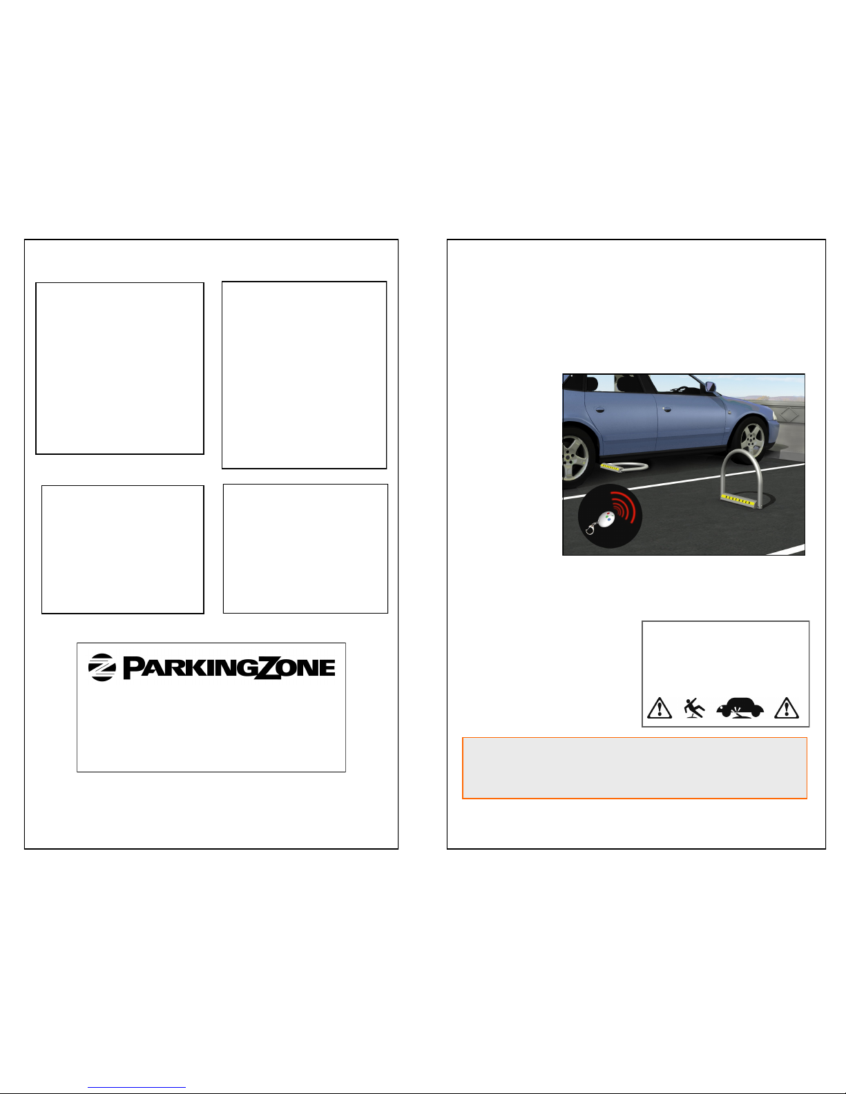
MySpot 500 is installed in the
middle of the space to block access to a parking space.
On command, the barrier is rotated down away from the incoming car to allow access to the
parking space. A second command will raise the barrier to the
vertical position where it guards
the space.
Owner Manual V1.02
We suggest that you keep this manual in the car’s glove compartment,
The manual will refresh your memory how to use the barrier, as well as
show you how to recognize when the batteries need replacing and how
to go about it.
WARNING! Barrier may cause pedes trians or users to trip over it.
Please install and pr ovide warning
signs accordingly. Note that Public
Liability should be in place.
The product has advanced features many of which are covered
in this manual.
Pacific Cascade Corporation
14208 NW 3rd Court, Suite 200
Vancouver, WA 98685
P: 360-574-9313 F: 360-574-9325
www.parkingzone.com
For assistance in using, installing, programming or troubleshoot-
ing, we recommend that you look up our video clips on You-
Tube.com Search using the term “MySpot 500 support”.
IMPORTANT
DEFENSE
The MySpot 500 barrier is designed
to absorb external frontal forces and
yiel d if they exceed a dangerous
point. The barrier will return on its
own to the upright position once the
external force has been removed.
The Defense works in both directions — if the barrier is forced towards the back of the parking space,
or if it is forced towards the front of
the parking space.
WARNING: The internal defense
spring can store damaging energy
when the barrier is abruptly released.
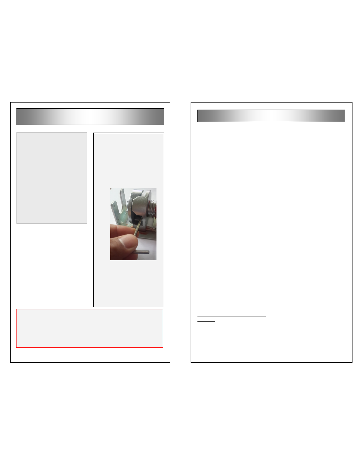
MANUAL RELEASE
If the barrier is stuck in the up or
down positions, you can release
the locking mechanism manually.
Use the M8 open-wrench to remove the vent in the back of the
housing, then insert the long arm
of the M3 hex wrench into the
housing until you hit the brake.
Apply a sideways force to the
left. This will force the brake to
the right (the hole in the housing
acts as a fulcrum). While holding
the brake in this position, manually lower or raise the barrier.
LOW BATTERY SIGNAL
When the unit detect s that the
battery is nearly discharged, the
barrier will “hesitate” for one sec-
ond at 45 degrees every time it is
commanded to go down. After 50
such warning cycles, the barrier
will refuse to go up any further,
until the batteries have been replaced.
the batteries and measure the
voltage across each one. The
voltage must be above 1.3 volt.
We recommend replacing a set of
batteries if any is below 1.40V to
save maintenance next time.
Fresh batteries should read over
1.55V.
There can be other reasons;
please consult our online troubleshooting wizard.
Barrier does not rise/drop fully
This is an indication that there is
resistance that blocks the movement of the barrier, or causes the
barrier to move slower than
usual. Watch the LEDs in the
front of the barrier. Send a command; the barrier should move
without the RED LED flashing
until it is stopped at the end of
travel (vertically up of horizontally
down).
A possible reason for slow movement or failure to reach the full up
and down positions may be due
to the barri er bei ng be nt/
misaligned (after a car bumped
into it).
Barrier does not lock in the Up
position
If the barrier moves properly and
reaches the vertical position, but
offers no resistance against push-
back at that position, there may
be a failure of the internal barrier
lock.
Contact the factory or your distributor.
Use of the Wizard
Visit our online self-diagnosing
wizard at:
ht t p: / /design a ted p ark i ng. com /
TS_500MS/index.php
The wiki is symptom driven. Find
the symptom, then navigate to
either more questions or to the
solution by clicking on the appropriate entry.
Troubleshooting continued

Troubleshooting
DIAGNOSTICS LEDs
The MySpot 500 has 2 LEDs
in the front panel, visible
through a clear hole in the yel-
low “reserved” label. The loca-
tion is immediately to the left of
the “S”. One LED is green and
the other is red.
BARRIER IS DOWN, Does
not rise on command
press the center button on the
remote and observe the LEDs.
If the red LED flashes in response to the command, it
means that the remote is not
paired with the barrier.
One cause can be a mix-
up be t we en r emot es
paired for different barriers
Another cause can be the
introduction of a new remote that was not previously paired.
A 3rd possibility is that the
barrier unit was rebooted
and thus lost it pairing history.
See page 5 for pairing pro-
cedures.
If the green LED flashes in response to the command, it
means that the radio link is OK
and the cause of the problem
could be one of the list below:
The barrier is mechanically
prevented from rising (Red
LED will flash during movement)
The position sensor informa-
tion inside the barrier unit
got corrupted. Reset the
power to the unit (see page
15), then send a couple of
commands to exercise the
barrier up and down.
If neither LEDs flashes, a likely
cause for no response is that the
barrier batteries are run down or
that they “jumped” out of the
holder during shipping. Access
CONTACT US for assistance
1-360-574-9313 or
orders@parkingzone.com
YouTube.com “myspot 500 support”
OPERATION
The MySpot 500 is
prov i d e d w i t h 2
handhel d remotes
(“fobs”) that have
been factory programm ed to control this individual barrier. Only
button #2 on these remotes is
pre-programmed to control the
barrier.
The fobs will control the barrier
from a distance of 1 foot to 40
feet (0.3 meter to 12 meters) .
You need to hold the fob horizontally and face the front of the bar-
rier (the “Reserved” yellow strip
on the housing of the barrier).
Pressing button 2 on the fob will
raise the barrier if it was down, or
lower it if the barrier was up.
If the barrier hits resistance on its
way up, it will stop and reverse
itself to bring the barrie r back
down. If the barrier hits resistance on the way down, it will
stop and await a new command.
Before You Install
BEFORE YOU OPEN THE CART ON:
If external damage to the packing is evident, notify the carrier immediately.
Shipping damage is not covered by the manufacturer’s warranty.
KIT CONTENTS
The kit includes the following.
Flat open wrench M8
Hex L wrench M3
4 concrete expansion anchors
2 HTm remote control fobs
This manual
TOOLS REQUIRED—CONCRETE
The foll owing tools are requi re to
install the MySpot 500 on concrete.
Hammer drill
10 mm drill bit
M13 (1/2”) open end wrench
Hammer
TOOLS REQUIRED—ASPHALT
The following tools and supplies are
require to install the MySpot 500 on
asphalt.
AK-4 anchor kit
Hammer drill
7/8” drill bit, 6” long
1/2” open end wrench
Hammer
Grease or anti-seize paste
Install at io n in struc ti ons beg in on
page 7.
 Loading...