

Page 1

®
MAX
Wireless to the
REVISION: 1 / VERSION: 031104a / DATE: October 2004
USB1500
Wireless PC LAN Adapter
USER’S GUIDE
WWW.PARKERVISION.COM
Page 2

®
22
USB1500 Wireless PC LAN Adapter
COPYRIGHT
©2003 ParkerVision Inc. All rights reserved. ParkerVision Wireless™ and D2D™ Technology are
registered trademarks of ParkerVision Inc. All specifi cations are subject to change without notice.
May include one or more of the following patents: US6421534, US6049706, US6266518, US6061555,
US6061551,US6353735, US6091940, US6370371 Additional Patents Pending.
Designed and manufactured in the USA.
FCC INTERFERENCE STATEMENT
FCC ID: JFE-D2D00002
This device complies with Part 15 of the FCC rules. Operation is subject to the following two conditions:
This device may not cause harmful interference.
This device must accept any interference received, including interference that may cause undesired operations.
This equipment has been tested and found to comply with the limits for a Class B digital device pursuant to Part 15 of the FCC
Rules. These limits are designed to provide reasonable protection against harmful interference in a commercial environment.
This equipment generates, uses, and can radiate radio frequency energy, and if not used in accordance with the instructions,
may cause harmful interference to radio communications.
If this equipment does cause harmful interference to radio/television reception, which can be determined by turning the
equipment off and on, the user is encouraged to try to correct the interference by one of more of the following measures:
Reorient or relocate the receiving antenna.
Increase the separation between the equipment and the receiver.
Connect the equipment to an outlet on a circuit different from that to which the receiver is connected.
Consult the dealer or an experienced radio/TV technician for help.
INFORMATION TO USER: THE USER’S MANUAL OR INSTRUCTION MANUAL FOR
AN INTENTIONAL OR UNINTENTIONAL RADIATOR SHALL CAUTION THE USER
THAT CHANGES OR MODIFICATIONS NOT EXPRESSLY APPROVED BY THE PARTY
RESPONSIBLE FOR COMPLIANCE COULD VOID THE USER’S AUTHORITY TO
OPERATE THE EQUIPMENT.
“FCC RF exposure requirements: When in operation, the device should be located such that it
is more than 20 cm. away from people and their person. This transmitter is restricted for use
with the specifi c antenna(s) tested in the application for Certifi cation. The antenna(s) used for
this transmitter must not be co-located or operating in conjunction with any other antenna or
transmitter.”
Page 3

®
55
USB1500 Wireless PC LAN Adapter
Table of Contents
Copyright ................................................................................................................................................................ 2
Federal Communications Commission(FCC) Interference Statement .................................................................... 2
Limited Warranty ..................................................................................................................................................... 3
Customer Support .................................................................................................................................................4
Introduction .........................................................................................................................................................6
PART I. GETTING STARTED ..................................................................................................................................... 7
Chapter 1 Getting to Know Your ParkerVision USB Wireless LAN Adapter .............................................................8
1.1 Introduction ............................................................................................................................................. 8
1.2 Features of the ParkerVision USB Wireless LAN Adapter .................................................................... 8
1.3 Applications ............................................................................................................................................ 8
Chapter 2 Software Installation ............................................................................................................................. 10
2.1 Installing the ParkerVision USB Software ............................................................................................ 10
2.2 Important Windows XP Information ...........................................................................................................13
Chapter 3 ParkerVision Wireless USB LAN Adapter Hardware Installation ........................................................ 15
3.1 System Requirements ............................................................................................................................ 15
3.2 Installing the ParkerVision USB1500 LAN Adapter ............................................................................. 15
PART II. ADVANCED MANAGEMENT ................................................................................................................ 17
Chapter 4 D2D/ParkerVision Management Utility ............................................................................................... 18
4.1 Confi guration ......................................................................................................................................... 18
4.2 Using the D2D/ParkerVision Management Utility ............................................................................... 19
4.3 Available Connections Section ............................................................................................................. 20
4.4 Current Connection Selection ................................................................................................................ 21
4.5 Access Tray Section .............................................................................................................................. 21
4.6 AD-HOC and AP Modes ....................................................................................................................... 22
4.7 SSID ...................................................................................................................................................... 23
4.8 WEP Encryption ................................................................................................................................... 23
PART III. ADDITIONAL INFORMATION .............................................................................................................. 24
Chapter 5 Troubleshooting ..........................................................................................................................................25
Appendix A - Network Confi guration .................................................................................................................. 28
Appendix B - Hardware Specifi cation .................................................................................................................. 31
Appendix C - Uninstalling the D2D ParkerVision Software ............................................................................... 32
Index ........................................................................................................................................................................... 35
Glossary......... .............................................................................................................................................................. 37
Page 4

®
66
USB1500 Wireless PC LAN Adapter
INTRODUCTION
All ParkerVision Wireless products are designed
and manufactured by ParkerVision. Products are
fully compliant with IEEE 802.11b standards and are
optimized to provide maximum possible speed and
bandwidth through your Internet connection for fastest
uploads and downloads.
The distance capabilities of your wireless network
equipment directly affect your signal quality. Distance
capabilities are usually stated in terms of outdoor, open
fi eld reach. However, this reach is greatly diminished
indoors by walls, doors, construction techniques and
appliances that may block the radio signal. A wireless
network adapter that tests outdoors at 200 feet could, in
an indoor environment, provide 20 feet in one direction
and as little as 5 or 10 feet in another direction. Factors
such as building materials, fl oor plans and furnishings
can greatly impact the signal range, quality and rate of
data transmission. The extent to which your signal is
affected varies greatly depending on your environment.
Wireless network products powered by D2D technology
will provide better performance than other products
because they can achieve open fi eld distances of up
to one mile, (when a D2D enabled adapter is used in
conjunction with a D2D enabled base station). The D2D
adapter alone provides 3 to 7 times the distance of other
leading brands. This is suffi cient to reach all rooms in
most homes or small offi ces.
Page 5

®
77
USB1500 Wireless PC LAN Adapter
Part I
Getting Started
The following chapters are
structured as a step-by-step
guide to help you connect,
install and setup your
ParkerVision Wireless USB
LAN Adapter.
Page 6

®
88
USB1500 Wireless PC LAN Adapter
Chapter 1 :
Getting to Know Your ParkerVision
Wireless LAN Adapter
This chapter introduces the main features of the ParkerVision Wireless LAN Adapter
1.1 Introduction
The ParkerVision Wireless PC LAN Adapter is an 11 Mbps IEEE 802.11b wireless USB
adapter and has a standard USB port which connects to a standard computer USB port. Its
maximum 11 Mbps data rate gives equivalent Ethernet speed to access corporate networks,
home networks, or the Internet in a wireless environment. The ParkerVision Wireless USB
LAN Adapter gives you wireless communication with any 802.11b-compliant product, allowing
you to stay connected anywhere within a coverage area.
1.2 Features of the ParkerVision Wireless PC LAN Adapter
The following are the essential features of the ParkerVision Wireless USB LAN Adapter .
• Supports data rate of 1,2, 5.5 and 11 Mbps
• Range of one mile in an open environment, when used with a ParkerVision wireless access
point
• Supports Point-to-Point and Point-to-Multi-point access
• Seamless connectivity to wired Ethernet and computer Network LAN
• Helps to augment existing networks quickly and easily
• Direct Sequence Spread Spectrum (DSSS) technology provides robust, interference resistant, and secure wireless connections capabilities
• Network connectivity minus the cost of cabling
• Supports, Windows 2000/XP
• Supports Plug and Play
• Ease of installation
• Flexibility and mobility to locate or move networked computers
1.3 Applications
The ParkerVision Wireless LAN Adapter offers fast, reliable and cost-effective solutions for
wireless networks. They include:
• Remote Access capability to Corporate Networks for email, fi le transfer and terminal
emulation access.
• Diffi cult to Wire Environments - For use in historical or old buildings, asbestos installations
and open areas where wiring is impossible to deploy.
• Frequently Changing Environments - For retailers, manufacturers and those who frequently
rear-range the workplace or change locations.
• Temporary LAN’s for Special Projects or During Peak Time - For trade shows, exhibitions
Page 7

®
99
USB1500 Wireless PC LAN Adapter
and construction sites where a temporary network is required. For retailers, airline and shipping
companies who need additional workstations during peak periods. For auditors requiring
workgroups at customer sites.
• Database Access for Mobile Users - Doctors, nurses, retailers who need to access their
databases on the move in a hospital, retail store, offi ce or campus.
• SOHO (Small Offi ce and Home Offi ce) Users - SOHO users who need easy and quick
installation of a small computer network.
• High Security Connection - Flexible, secure and quick installations, with WEP Encryption.
Page 8
®
1010
USB1500 Wireless PC LAN Adapter
Chapter 2 :
Software Installation
This chapter will guide you through the installation of the ParkerVision Software
Make sure that you install the software onto your computer
BEFORE you install the ParkerVision Wireless USB LAN Adapter!
The ParkerVision D2D Wireless USB LAN Adapter works with Windows XP and 2000
Operating Systems.
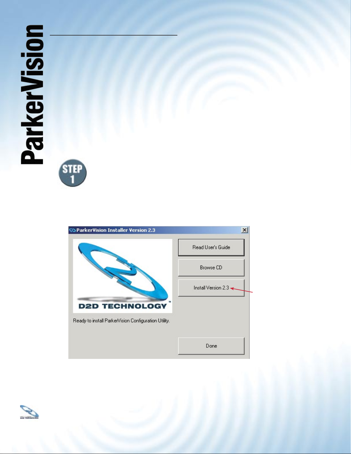
Insert the CD ROM into the CD ROM drive.
Most computers will Auto-Run the installation software, and the window below
will appear. If your computer does not Auto-Run, open up “My Computer” (this
icon is generally located on the desktop) and navigate to your CD ROM Drive.
Click this drive to see the list of fi les and folders located on the drive. Double
click the fi le named “setup.exe”
Click INSTALL VERSION 2.3
The window below will open.
Page 9
®
1111
USB1500 Wireless PC LAN Adapter
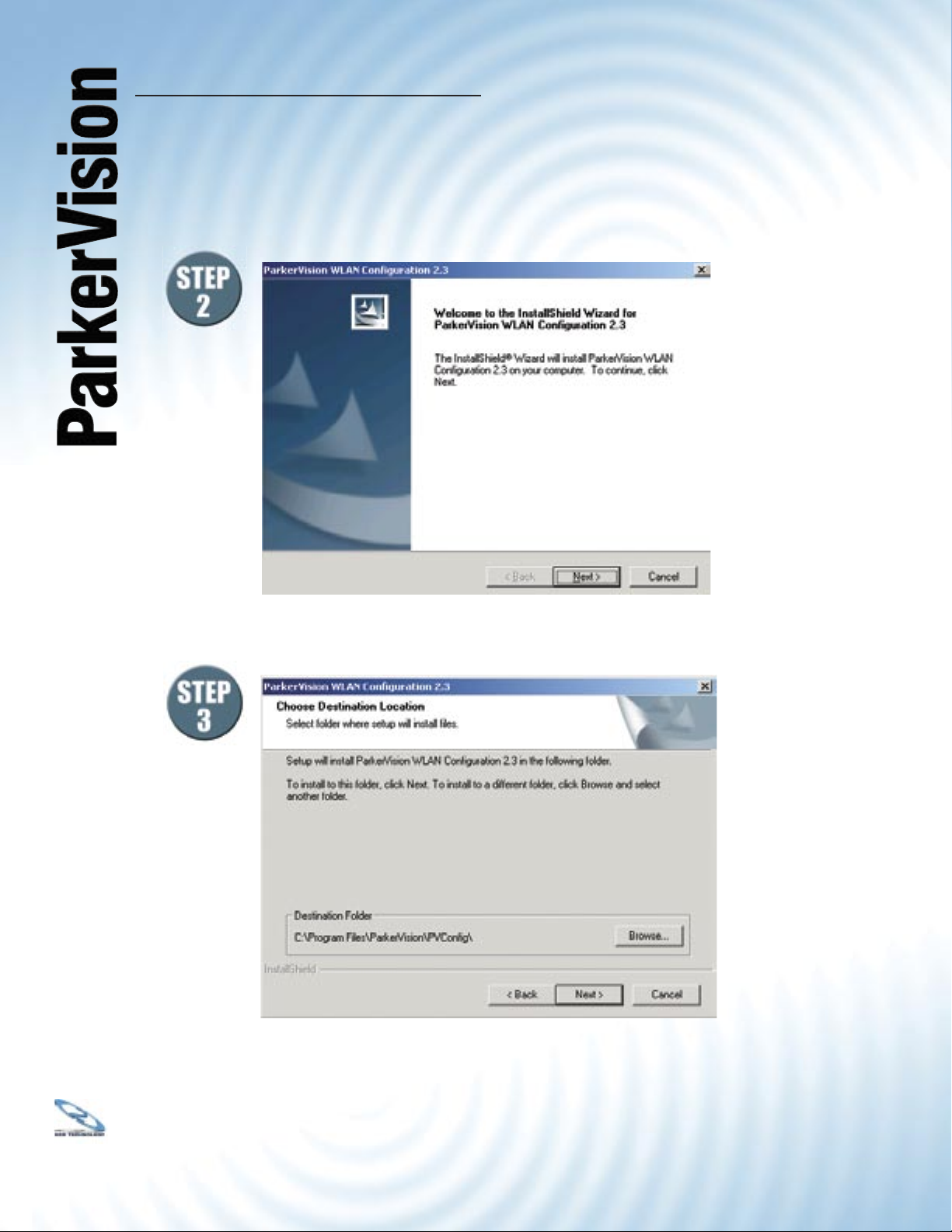
2.1 Installing the ParkerVision Software - Continued
The following screen will be displayed. Click NEXT to continue.
Select the install folder.
Click NEXT to install the ParkerVision software in the default folder as shown.
We do not recommend using an alternate location.
Click NEXT to continue.
Page 10
®
1212
USB1500 Wireless PC LAN Adapter
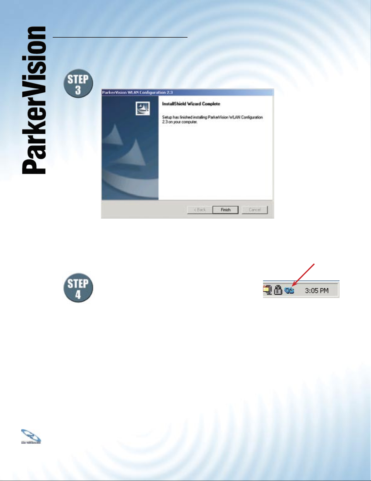
STEP 3 CONTINUED: Select FINISH at the following screen. This will complete
the installation of the ParkerVision software.
If the screen above does not appear, RESTART your computer by clicking START,
then SHUT DOWN, then RESTART. Once your computer has restarted, continue the
installation by following the
steps below:
Double Click this icon
in the System Tray
Please connect the USB1500 Wireless
LAN Cable into your computer’s USB port.
Double click the ParkerVision USB1500
icon on your desktop.
The ParkerVision Utility is now running in the background and has
placed an icon in the lower right System Tray.
Double-click on this icon in the System Tray as shown to the right.
NOTE: Windows 2000 Users can now go to CHAPTER 3 of this Manual
to complete the hardware installation and confi guration process.
For Windows XP Users:
Double clicking the ParkerVision USB1500 icon may cause the following message to appear:
“Windows Zero Confi guration was detected.
Please disable Windows Wireless Network Control.”
If you see this message, for best performance, you will now want to TURN OFF or Disable
Windows’ control of wireless networking. Proceed to the next page and follow the steps
shown to complete this process.
Page 11
®
1313
USB1500 Wireless PC LAN Adapter
2.2 IMPORTANT INFORMATION FOR WINDOWS XP USERS ONLY
For Windows XP Users Only: In order to achieve the best possible performance of the
USB1500 Wireless LAN adapter in your computer it is necessary to make a change
in the way Windows XP handles your computer’s wireless networking connections.
After your USB1500 LAN Adapter is installed and confi gured in your wireless network,
you will want to follow the instructions below to make this change in the Windows confi guration.
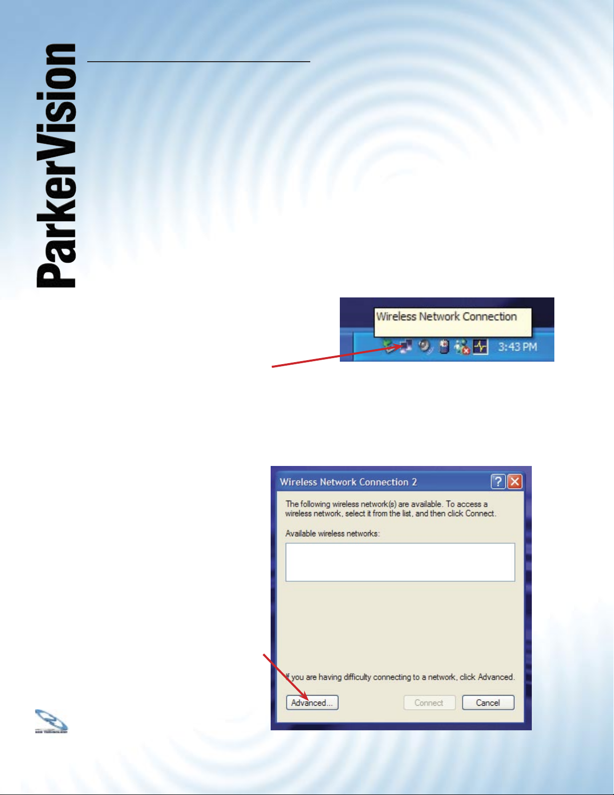
Step 1: Find the wireless networking connection icon in the System Tray, located in the
lower right hand corner of your screen, or at the far end of your Start Bar if you have it
docked to a location different from the screen bottom.
Double Click this icon
to access the Wireless
Network Connection
Properties
Step 2: Click this icon, which will bring up the Properties Dialog for the
wireless network connection that your computer is part of.
Double Click the
Advanced Button
Page 12

®
1414
USB1500 Wireless PC LAN Adapter
2.2 IMPORTANT INFORMATION FOR WINDOWS XP USERS - Continued
Step 3: Selecting the “Advanced Button” on the previous screen will bring up the
window shown below. Select the “Wireless Networks” tab, and note the box to the left
of the line “Use Windows to confi gure my wireless network settings.”
Step 4: If this box has a check mark in it, click in the box to REMOVE THE CHECK
MARK.
Step 5: Click OK to close this Window.
Click Here to
Remove the
Check Mark
Page 13

®
USB1500 Wireless PC LAN Adapter
Chapter 3 :
Hardware Installation
This chapter will guide you through the installation of the ParkerVision Wireless
LAN Adapter into your computer
3.1 System Requirements
• Operational USB Port
• Windows 2000/XP Operating System.
• 500 Kbytes free hard disk space (minimum) for driver and utility program installation.
• 128 MB RAM
• USB Cable
1515
3.2 Installing the ParkerVision USB Wireless LAN Adapter
Note: If you installed your adapter at the end of the last chapter, you can proceed to the next
page of this manual.
Follow the procedure shown next to install the ParkerVision Wireless USB LAN Adapter.
Refer to the appendix for important safety instructions.
Step 1. Locate available USB port on your notebook or desktop computer.
Step 2. Connect the USB cable to the ParkerVision USB Wireless LAN adapter.
Connect the other end of the cable to an open USB port on your computer.
Never force, bend or twist the USB plug into the USB port on either the
computer or the USB wireless LAN adapter
Insert the USB cable’s plug into the socket on the rear
of the HZ1500USB Adapter, then insert the other end
into an available USB port on your computer.
Page 14

®
1616
USB1500 Wireless PC LAN Adapter
The USB port does not support “hot swapping”. Removing the ParkerVision
Wireless LAN Adapter from the USB port when power to your computer is on
may cause the software to lock. You should always disable the ParkerVision
Wireless LAN Adapter prior to removal to allow Windows to log off from the
network server.
LED COLOR STATUS DESCRIPTION
POWER
Green On The ParkerVision Wireless LAN Adapter is receiving power.
LINK
Orange On The ParkerVision Wireless LAN Adapter has a successful wireless
connection.
Blinking The ParkerVision Wireless LAN Adapter is sending/receiving data
through the wireless connection.
Windows will automatically detect the HZ1500USB Wireless USB LAN Adapter and the FOUND
NEW HARDWARE Wizard Dialog Box will appear. Follow the on-screen instructions to install the
ParkerVision Wireless driver. If the Wireless LAN Adapter is not inserted properly, the following error
message will appear:
To confi rm proper installation of the ParkerVision-Wireless LAN Adapter:
• Right-Click MY COMPUTER from the Windows desktop.
• Click PROPERTIES
• Open DEVICE MANAGER
• Select the HARDWARE folder tab, and then click the DEVICE MANAGER button.
• Double-click NETWORK ADAPTERS. No special markers should appear next to the HZ1500USB
Wireless LAN Adapter selection.
• Double-click HZ1500USB Wireless LAN Adapter. Refer to the tab labeled GENERAL. The DEVICE
STATUS Window will indicate that the device is working properly.
For Windows 2000 users, a DIGITAL SIGNATURE NOT FOUND
message may appear. Simply select YES to proceed.
For Windows XP users, a WINDOWS LOGO TESTING NOT FOUND dialog box may appear. Click
CONTINUE ANYWAY to proceed. ParkerVision Wireless D2D software has been tested to work
with Windows XP, and the installation should be continued with confi dence.
Page 15

®
1717
USB1500 Wireless PC LAN Adapter
Part II
Advanced Management
The following chapters will show
you how to manage and confi gure
advanced parameters of your
ParkerVision USB Wireless LAN
Adapter.
Page 16

®
1818
USB1500 Wireless PC LAN Adapter
Chapter 4 :
ParkerVision Wireless D2D
Management Utility
This chapter will guide you through confi guring the Management Utility for the LAN Adapter
4.1 Confi guration
ParkerVision Wireless D2D Management Utility will assist in setting up and customizing your wireless
network. The D2D Management Utility will provide you with information regarding signal quality and link
conditions as well as let you modify various wireless parameters.
To access the ParkerVision-Wireless D2D Management Utility double-click the USB1500 shortcut
found on the desktop. The D2D Management Utility can also be accessed by double-clicking the
ParkerVision (H) icon that appears in the Windows System Tray (bottom-right corner of the task
bar). The shortcut as well as the icon are shown below.
SysTray
Desktop
Icon
The shortcut is automatically placed on the desktop after driver installation is complete.
Clicking the access icon (tool button) in the lower-right corner will open the D2D Management
Utility. The ParkerVision (H) icon will appear in the System Tray only if the option is selected
from the D2D Management Utility.
The System Tray (SysTray) can be found on one end of the task bar on the Microsoft
Windows desktop. Icons for memory-resident applications that execute continuously in the
background will be found here. These may include such things as the time-clock, anti-virus
software, and speaker volume as shown above.
Icons
Page 17

®
1919
USB1500 Wireless PC LAN Adapter
4.2 Confi guration - Using the D2D/ParkerVision Management Utility
The D2D Confi guration Dialog Box is displayed as shown below and consists of three primary
sections. From here, different connections may be detected, confi gured, and stored.
Available
Connections
Section
Current
Connections
Section
Access Tray
Section
The Above Sections are covered individually on the pages that follow.
Page 18

®
2020
USB1500 Wireless PC LAN Adapter
4.3 AVAILABLE CONNECTIONS SECTION - Continued
The top-most section of the D2D Confi guration Dialog Box shows the available connections. The
available connections will be displayed from a scan performed when the software was started, or
when the scan button was clicked.
To begin using the USB1500 Wireless LAN Adapter immediately, highlight the desired
available connection and select CONNECT.
The following describes information found in the AVAILABLE CONNECTIONS area of the confi guration
Dialog Box.
• SSID: Identifi es the name of the network in use through the access point
that is being utilized.
• TYPE: Indicates the operating mode of the ParkerVision-Wireless LAN Adapter.
These modes are AP (Access Point/Infrastructure) and Ad-Hoc. The next
section of the manual covers this in more detail.
• CHANNEL: Indicates the wireless channel that is currently in use.
• SIGNAL: Indicates the radio frequency signal strength.
• WEP: Indicates the encryption status (security setting) of the device. If WEP is off,
there is no encryption. If it is on, settings options include 64-bit and
128-bit WEP.
• LAST SCAN: Gives the date and time stamp for the last successful scan.
• CONNECT: Connects to the selected network
• SCAN: Performs a check to fi nd wireless channels available for connection
Page 19

®
2121
USB1500 Wireless PC LAN Adapter
4.4 CURRENT CONNECTION SECTION
This section shows the connection that is currently active, giving the status of each category described
in the AVAILABLE CONNECTION SECTION on the previous page. The SPEED indicates the rate of
data transfer as dictated by the Access Point to which the Wireless LAN Adapter is connected.
4.5 ACCESS TRAY SECTION
If the START IN SYSTEM TRAY option is toggled, the ParkerVision (H) icon will appear in the
system tray on start-up.
• Click the www.parkervision.com button to access the ParkerVision-Wireless home page.
• Click the HELP option to view the user manual
• Click DONE to exit the D2D Management Utility
• Click OPTIONS to set the options shown below
• SSID is broadcast by the Access Point or in Ad-Hoc by all
members in the connection. Occasionally SSID is hidden
and the user needs to input the correct name.
• Channel can be set by the user when in Ad-Hoc. In AP
Mode, the Access Point sets the channel.
• Connect to Access Point or Ad-Hoc
• Select the appropriate WEP encryption option: Off,
64-bit, or 128-bit.
Most PUBLIC locations leave WEP off.
PRIVATE Ad-Hoc connections will default to WEP 64-bit
enabled. The exact key must match the AP or Ad-Hoc
member, i.e. Key 1: 3451237890. Connection is established
even if the key is incorrect, however, data will not be allowed
to transfer with the correct key. Four unique keys can be
remembered, one is selected as the default for use when
WEP is enabled. Verify with your IT professional the setting
for your network.
Page 20

®
2222
USB1500 Wireless PC LAN Adapter
4.6 MORE ON AD-HOC AND AP MODES
Ad-Hoc Mode (Peer-to-Peer Workgroup)
The Institute of Electrical and Electronics Engineers (IEEE) standard for wireless LAN’s (WLAN’s),
802.11 offers two methods for confi guring a wireless network — Ad-Hoc and infrastructure (Access
Point). In an Ad-Hoc network, computers are brought together as needed. In this instance, there
are no fi xed points to the network — each node can generally communicate with any other node.
There is no Access Point involved in this confi guration. This enables the set up and use of a small
wireless workgroup and allows workgroup members to exchange data or share printers as supported
by Microsoft Networking in the various Windows operating systems. To set up an Ad-Hoc workgroup
operating with standard protocols:
• Set all stations to connect in Ad-Hoc mode (or Peer-to-Peer workgroup mode).
• Set all stations to use the same network name (or SSID).
• Set all stations to use the same wireless channel for communication.
• Set all stations to either disable the WEP encryption key, or set all stations to use an identical WEP
encryption key.
AP Mode (Infrastructure Mode)
With a wireless Access Point (AP), you can put the ParkerVision-Wireless PC LAN into AP
(Infrastructure) mode. It provides wireless connectivity to multiple wireless network devices within a
fi xed range or area of coverage, interacting with a wireless node by way of an antenna. In AP Mode,
the wireless Access Point converts airwave data into wired Ethernet data, acting as a bridge between
the wired LAN and wireless clients. Connecting multiple Access Points via a wired Ethernet backbone
can further extend the wireless network coverage. As a mobile computing device moves out of the
range of one Access Point, it moves into the range of another. As a result, wireless clients can freely
roam from one Access Point domain to another and still maintain seamless network connection. To set
up an AP network operating with standard protocols, do the following:
• Set all wireless stations to connect in AP mode.
• Set all stations to use the same network name (or SSID).
• Set all wireless Access Points to use the same network name (or ESSID).
• Set all stations to disable the WEP encryption key, or set all stations to use an identical WEP
encryption key as used by the Access Point.
• Set up wireless channels used by individual Access Points. (It is not necessary to set channels on
the stations as the stations will automatically scan through all channels for the nearest Access Point.
• You should consult your access point documentation for the available options.
Page 21

®
2323
USB1500 Wireless PC LAN Adapter
4.7 MORE ON SSID
Service Set Identifi cation (SSID)
The Service Set Identifi cation (SSID) is a thirty-two alphanumeric character (maximum)
string identifying the wireless local area network. ParkerVision-Wireless refers to the SSID as
network name. For stations to communicate with each other, all stations must be confi gured
with the same SSID. A wireless LAN consisting of nodes operating in Ad-Hoc confi guration
without an Access Point is called a Basic Service Set (BSS). All nodes in a BSS must use the
same Basic Service Set ID (BSSID). In an AP (Access Point) confi guration, multiple BSS can
be confi gured to form an Extended Service Set (ESS). In this confi guration, the Access Points
are confi gured with the same Extended Service Set ID (ESSID). Wireless clients confi gured
with the same ESSID can freely roam from one Access Point domain to another and still
maintain a seamless connection to the network.
4.8 MORE ON WEP ENCRYPTION
Authentication and WEP Encryption
Wireless links are vulnerable to information theft. To provide a certain level of security,
IEEE 802.11 standard has defi ned two types of authentication methods, Open System and
Shared Key. Open System authentication is a null algorithm. Shared Key authentication is an
algorithm where both the transmitting node and the receiving node share an authentication
key to perform a checksum on the original message. By default, IEEE 802.11 wireless devices
operate in an open system network. Wired Equivalent Privacy (WEP) data encryption is
utilized when the wireless nodes or access points are confi gured to operate in Shared Key
authentication mode. ParkerVision-Wireless utilizes the following 802.11b solutions: the
standard based 64-bit WEP data encryption and 128-bit WEP data encryption. The 64-bit
WEP data encryption method allows for a fi ve-character (40 bits) KEY. Additionally, 24 factoryset bits are added to the 40-bit input to generate a 64-bit encryption key. (The 24 factory-set
bits are not user confi gurable.) This encryption key will be used to encrypt/decrypt all data
transmitted via the wireless interface. The 128-bit WEP data encryption method consists of
104 confi gurable bits. Similar to the 64-bit WEP data encryption method, the remaining 24 bits
are factory set and not user confi gurable.
Page 22

®
2424
USB1500 Wireless PC LAN Adapter
Part III
Additional Information
This part includes Troubleshooting,
Appendices, and the Index.
Page 23

®
2525
USB1500 Wireless PC LAN Adapter
Chapter 5 :
Troubleshooting
This chapter covers potential problems and the possible remedies. After each problem
description, some instructions are provided to help you diagnose and solve the problem.
5.1 Problems During Driver Installation
PROBLEM CORRECTIVE ACTION
The ParkerVision Wireless
USB LAN Adapter is not
working after the driver
installation
Make sure the driver software is installed BEFORE you connect your wireless USB LAN
adapter to your computer. Failure to install the software fi rst may result in the LAN adapter
being recognized incorrectly.
Reonnect the USB adapter to your computer’s port again. The Power and Link LED should
be on if the adapter is properly inserted.
Windows does not autodetect the ParkerVision
Wireless USB LAN Adapter
Make sure there is no hardware confl ict between your ParkerVision Wireless LAN Adapter
and other hardware in your computer. If there is a confl ict, you need to set your I/O and
IRQ manually.
Restart your computer.
Do a manual scan of your computer hardware.
In Windows 2000, click Start, Settings, Control Panel, System, Hardware, Hardware
Wizard.
In Windows XP, click Start, Control Panel, Performance and Maintenance, System,
Hardware, Device Manager. Then Right-click on your computer name and select Scan
for Hardware Changes.
Check your USB port and make sure there is no hardware confl ict.
Try an alternate USB port if one is available on your computer.
Contact ParkerVision Customer Support
Page 24

®
2626
USB1500 Wireless PC LAN Adapter
Chapter 5 - Troubleshooting - Continued
5.2 Problems With the Utility Confi guration
PROBLEM CORRECTIVE ACTION
While starting the confi guration
utility, the program starts up and
terminates immediately with no
errors.
The D2D/ParkerVision software may not recognize that the USB adapter has been
connected. Try removing and re-connecting the USB plugs. Make sure that Windows is
recognizing the adapter when it is inserted.
Note for Windows XP users: Another reason the utility may terminate results from
Windows XP controlling the adapter services at installation time. You may check this
with the following steps: Click Start, Control Panel. From Control Panel, select Network,
then Wireless Network Settings, and uncheck the “Use Windows to confi gure my wireless
network settings.” More information on this can be found in this manual in Section 4.11.
5.3 Problems With Access Point Settings
PROBLEM CORRECTIVE ACTION
Problems with AP settings. Make sure that the Access Point (AP) and the associated computer are turned on.
Check to see if the access point is displayed in the available connections section of the
D2D/ParkerVision Management Utility.
From a Windows Command Prompt, use the Ping Command to test connectivity to the
Access Point. Consult your Access Point manual for the appropriate IP Address.
Consult your Access Point Manual for additional troubleshooting tips.
Page 25

®
2727
USB1500 Wireless PC LAN Adapter
Chapter 5 - Troubleshooting - Continued
5.4 Problems Communicating With the Computer
PROBLEM CORRECTIVE ACTION
The ParkerVision USB Wireless
LAN Adapter client cannot
communicate with the other
computer on the Ethernet when
the Infrastructure mode is
confi gured.
Make sure that the AP and the associated computer are on.
Make sure your computer and the AP use the same SSID.
Make sure both computers are associated with the Access Point.
Use the Windows Ping Command to test communications to the access point’s IP
Address. Consult your Access Point documentation for the address settings. If you
can Ping the Access Point, you should then attempt to Ping the second computer. The
IPCONFIG command will display a computer assigned IP Address when entered from a
Windows Command Prompt.
ParkerVision Status Utility
Button displays No Signal.
There is too much radio
interference (for example
microwave oven or cordless
telephone) around your
wireless network.
Use the Site Survey utility to verify operating radio channel has low interference. Change
the AP and all the stations within the BSS to another radio channel if interference is high.
Make sure that the computer and the AP share the same security option and key.
Move your computer closer to the AP within the transmission range.
Relocate or reduce the radio interference.
Page 26

®
2828
USB1500 Wireless PC LAN Adapter
Appendix A :
Network Confi guration
The ParkerVision Wireless USB1500 Wireless LAN Adapter supports the same network
confi guration options of Legacy Ethernet LAN’s as defi ned by the IEEE 802 standard.
The ParkerVision Wireless LAN Adapter can be confi gured as:
• Ad-hoc for departmental or SOHO LAN’s.
• Infrastructure for enterprise LAN’s.
• LAN-interconnection for point-to-point link as a campus backbone.
Ad-hoc Wireless LAN Topology
Page 27
®
2929
USB1500 Wireless PC LAN Adapter
Ad-hoc Wireless LAN Topology - Continued
An Ad-hoc wireless LAN is a group of computers, each equipped with one wireless adapter,
and connected as an independent wireless LAN. Computers in a specifi c Ad-hoc wireless
LAN must be confi gured on the same radio channel. An Ad-hoc wireless LAN is available at a
departmental scale for a branch or SOHO operation.
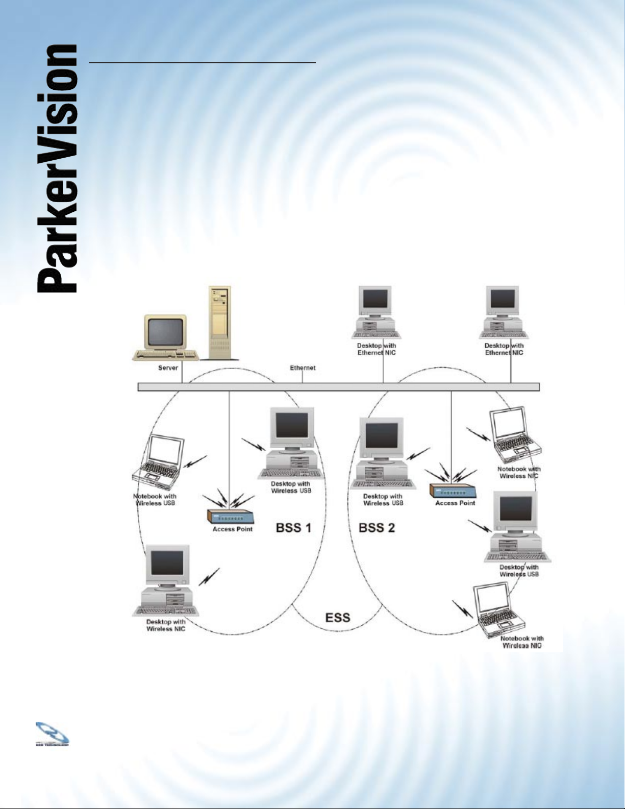
Wireless LAN Topology Infrastructure
Page 28

®
3030
USB1500 Wireless PC LAN Adapter
Ad-hoc Wireless LAN Topology - Continued
The ParkerVision Wireless LAN Adapter provides access to a wired LAN for wireless computers.
An integrated wireless and wired LAN is called an Infrastructure confi guration. A group of
wireless LAN computer users and an Access Point constitute a Basic Service Set (BSS).
Each wireless-equipped computer in this BSS can talk to any computer in the wired LAN
infrastructure via the Access Point.
Infrastructure confi guration will extend the accessibility of a wireless station to the wired LAN.
Multiple Access Points will allow roaming and it will increase the transmission range. The
Access Point is also able to forward data within its BSS. The effective transmission range in
an Infrastructure LAN is doubled.
Effective Transmission Range Example
Page 29

®
3131
USB1500 Wireless PC LAN Adapter
Appendix B :
Hardware Specifi cations
General ParkerVision USB1500 Wireless LAN Adapter Specifi cations
Operating Systems Supported Windows 2000 and XP
Standards IEEE 802.11b
Host Interface USB
Data Rates 1, 2, 5.5, 11 Mbps, with Auto-
Fallback Support
Modulation BPSK, QPSK, CCK
Range (typical) Open Environment: 1 Mile*
Closed Environment: 450 Feet*
Frequency Range ISM Band (2.4 to 2.4835 GHz)
Channels 1-11 United States (Approved
for use only in the United
States)
Wireless Security (WEP) Off, 64-bit, 128-bit
* A ParkerVision Access Point is required to achieve absolute maximum range.
Page 30

®
3232
USB1500 Wireless PC LAN Adapter
Appendix C :
Uninstalling the ParkerVision
Software
Should you wish to uninstall the ParkerVision Software from your Windows 2000 or XP computer, the
following steps should be followed:
Step 1: Locate the fi le WLAN1500 Uninstall.exe. This fi le is generally located in the folder in
which the ParkerVision software was installed, as shown in the example below. Select this fi le to run the
uninstall program.
Select NEXT to uninstall the software.
Click REMOVE
ALL INSTALLED
FEATURES.
Page 31

®
3333
USB1500 Wireless PC LAN Adapter
Uninstalling the ParkerVision Software - Continued
Step 2: After the remaining fi les associated with the ParkerVision/D2D software are removed, you will
see the following dialog box:
Click Finish to complete the uninstall of the ParkerVision software.
Page 32

®
3434
USB1500 Wireless PC LAN Adapter
Index
Term Page Term Page
128-bit 20
64-bit 20
USB Connector 13
802.11b 8
Access Tray Section 17, 21
Additional Information 25
Ad-Hoc 29
Ad-Hoc Mode 21
Ad-Hoc Wireless Topology 30, 31
Advanced 23
Advanced Management 15
Antenna 2
AP Mode 21
AP Settings 27
Applications 8
Auto Run 10
Available Connections 17, 18
Basic Service Set (BSS) 31
BSS 31
CD ROM 10
Channel 18
Channels 32
Check Mark 24
Computer 28
Connect 18
Connect Button 19
Copyright 2
Current Connections 17, 19
Customer Support 4
Data Rates 8, 32
Database 9
Digital Signature 14
Edit Section 20
Ethernet 28
FCC Interference Statement 2
Found New Hardware 14
Frequency Range 32
Guarantee 3
Hardware Installation 13
Hardware Specifi cations 32
Help 21
ParkerVision Status Monitor 16
ParkerVision Status Utility Button 28
Host Interface 32
Hot Swapping 14
Icon 16
IEEE 802.11b 6, 22, 32
Infrastructure 31
Introduction 6
Introduction 8
IPCONFIG 28
LAN 9, 29
Last Scan 18
LED 14
License Agreement 11
Management Utility 16
Modulation 32
Network Adapters 14
Network Confi guration 29
None 20
Package Contents 4
USB Standard 13
Peer-to-Peer 21
Plug and Play 8
Profi les Section 19
Properties Dialog 23
Radio Interference 28
Range 8, 32
Registration 4
Remote Access 8
Restart Computer 12
Scan 18
Scanned SSID 20
Security 9
Page 33

®
3535
USB1500 Wireless PC LAN Adapter
Index
Term Page
Service Set Identifi cation (SSID) 22
Signal 18
Site Survey 28
Software Installation 10
SOHO 9, 30
SSID 18, 20,
22, 28
System Requirements 4, 13
System Tray 16
SysTray 16
Table of Contents 5
Transmitter 2
Troubleshooting 25, 27,
28
Type 18
Uninstalling 33
United States 32
Use Windows to confi gure my
wireless network settings
Utility Confi guration 27
Warranty 3
WEP 18, 21,
Windows 2000 8, 32
Windows XP 8, 23, 24,
Wireless Network Connection 23
Wireless Security (WEP) 32
24
22
27, 32
Page 34

®
3636
USB1500 Wireless PC LAN Adapter
Glossary
Channel: The radio channel of a wireless network, 1 through 11.
Connect: Connect to an available network, or connect to a network using a specifi c profi le.
Delete: Delete a named profi le.
Done: Save changes and close the window.
Edit: Edit a named profi le.
Name: Profi le name, such as, “Work” or “Home”.
Options: Used to create ad hoc and infrastructure networks, and start the ParkerVision-
D2D user interface in the system tray.
Password: Enter a password, if required, to connect to a wireless network.
Profi le: A record that contains information about a wireless network such as SSID, WEP
keys, channel, and type of connection, e.g. AP or ad hoc.
Scan: Activates a search of all channels (1 through 11) searching for wireless networks.
Scanning…: Active indication of the scanning activity. If the radio seems to be in a state of
continuous “Scan”, it is likely that there are no wireless networks available.
Signal: Signal strength.
Status: State of the wireless connection, either connected or not connected.
Speed: The speed of the connection measured in Mbps, (Megabits per second).
SSID: Service Set Identifi er. An identifi cation broadcast, (or not), by an access point or
ad hoc node.
Type: Type of network, either infrastructure/access point, (AP), or ad hoc.
WEP: Wired equivalent privacy. A means of encrypting the radio signals, can be 40 bit,
64 bit, or 128 bit encryption.
 Loading...