

Page 1
®
SIGNAL
MAX
Quick Start
GUIDE
WIRELESS
WR1500
4-Port DSL/Cable
Router
www.parkervision.com
Page 2

®
3
WR1500 4-Port Wireless DSL/Cable Router
Congratulations on your purchase of the
ParkerVision WR1500 Wireless Router.
You have just purchased a wireless device that is guaranteed to provide the
best distance, best coverage, best throughput, and best technology of any
802.11b/802.11g-compatible Wi-Fi router or access point.
Please follow the instructions in this Quick Start Guide in order to achieve
the maximum performance of this product.
Once you have completed the steps in this guide, you will want to browse
the full, comprehensive manual on the CD ROM. This device features
many advanced settings. In the majority of applications, simply following
the procedures outlined in this Quick Start Guide will bring your WR1500 to
the scope of operation that meets your requirements.
available, and are described completely in the manual.
PACKAGE CONTENTS
• D2D™ Wireless WR1500 Wireless Router
• AC Power Adapter
• CAT-5 Ethernet Cable
• Manual on CD ROM
• Latest software always on-line at www.direct2data.com
Advanced options are
SYSTEM REQUIREMENTS
• Computer with a 10/100 Ethernet Port, an Internet ExplorerTM-6
compatible browser.
• ParkerVision WR1500 Wireless Router works with any 802.11b/802.11g compatible Wireless LAN network, communicating with other 802.11b/g
equipped computers with hard-wired PC laptop/desktops with an available
10/100 LAN Port.
Visit www.direct2data.com for information on ParkerVision’s
complete line of extended range Wireless LAN products.
This product is available for purchase in the U.S. and Canada.
CUSTOMER SUPPORT
You can access customer support online at
www.direct2data.com. This is the quickest way to access:
• Answers to Frequently Asked Questions
• Troubleshooting Guides
• Updated Drivers
• Manuals
You can also request help by sending an email to
support@direct2data.com or calling customer support directly at
1-800-231-1759. See the manual on the CD ROM for important
warranty and FCC information about this product.
Page 3
®
4
WR1500 4-Port Wireless DSL/Cable Router
Start Here!
INSTALLATION
This section will guide you through the installation of the WR1500.
Unpack your WR1500 and make sure that
everything is unwrapped and ready to begin.
First, either install, or make sure the antennas
for the WR1500 are securely installed onto the
rear panel of the unit.
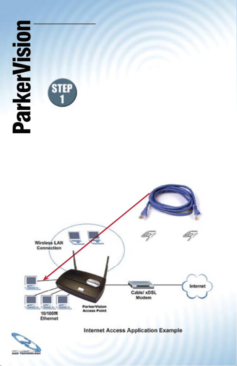
A CAT-5 Ethernet Cable is supplied to connect between your
computer and the WR1500. A picture of this type of cable is
shown below.
Also shown below is an illustration of a typical installation for
the WR1500.
The next page will describe the specifi cs of making these
connections.
Page 4

®
5
WR1500 4-Port Wireless DSL/Cable Router
The WR1500 ships with an internal IP address of 192.168.1.1,
which certain cable/DSL modems may also utilize. If your
cable/DSL modem has the same IP address as the WR1500
(192.168.1.1) you will not be able to connect during setup.
ParkerVision has already performed this procedure on your
WR1500, however, IF YOU RESET the WR1500 to factory
defaults you will need to repeat the following procedure.
Please reference on page 7 of this quick start guide
for the following process:
Step 1. Ensure the cable/DSL modem is not connected to
the WR1500, if it is, disconnect it now.
Step 2. Power the WR1500 by plugging the adapter into a
surge-protected electrical outlet.
Step 3. Connect the provided Ethernet cable into port 1 on
the WR1500 and the other end of the cable into your
computer’s Ethernet port.
Step 4. Reset the WR1500 by depressing the Reset button
(located on the back of the unit) using a paper clip
or pen until the system light on the top of the unit
begins to fl ash red. Once the system light begins to
fl ash red, release the Reset button.
Step 5. After reset, the system light will turn green indicating
normal operation.
Please reference on page 8 of this quick start guide
to prepare your computer to connect to the WR1500.
After you connect to the WR1500, you will need to change
the IP Address.
Continued next page
Page 5

®
Apply Reset
DHCP Setup
LAN TCP/IP
Windows Networking (NetBIOS over TCP/IP)
DHCP Server
IP Pool Starting Address
192.168.1.33
Pool Size
32
DNS Servers Assigned by DHCP Server
First DNS Server
Second DNS Server
Third DNS Server
From ISP
0.0.0.0
0.0.0.0
0.0.0.0
IP Address
IP Subnet Mask
Multicast
192.168.2.1
255.255.255.0
None
Allow between LAN and WAN
LAN
1
2
From ISP
From ISP
RIP Direction
RIP Version
Both
RIP-1
IP
Changing the IP Address
Step 1. On the LAN screen, change the IP Pool
Starting Address (Box 1 on the illustration below;
192.168.1.33 by default) to the recommended
setting of 192.168.2.33.
Step 2. Change the IP Address (Box 2 on the illustration
below; set to 192.168.1.1 by default) to the
recommended setting of 192.168.2.1.
6
Step 3. Click Apply at the bottom of the screen to save
the settings. Clicking Apply will cause you to lose
your connection to the Web Confi guration Utility.
Step 4. Turn off power to both the WR1500 and cable/DSL
modem.
Reconnecting the cable/DSL modem
Step 1. While both are powered off, reconnect the cable/
DSL modem to the WAN port on the WR1500. (See
Step 1 and Step 2 in the WR1500 Quick Start Guide).
Step 2. Power the router back on, wait until the status lights
are normal.
Step 3. Power the cable/DSL modem.
After you have performed these steps you should reboot the
computer and test the LAN/WAN connectivity. If you are still having
issues, ParkerVision Technical Support is available at 800.231.1759
or at support@parkervision.com.
Page 6
®
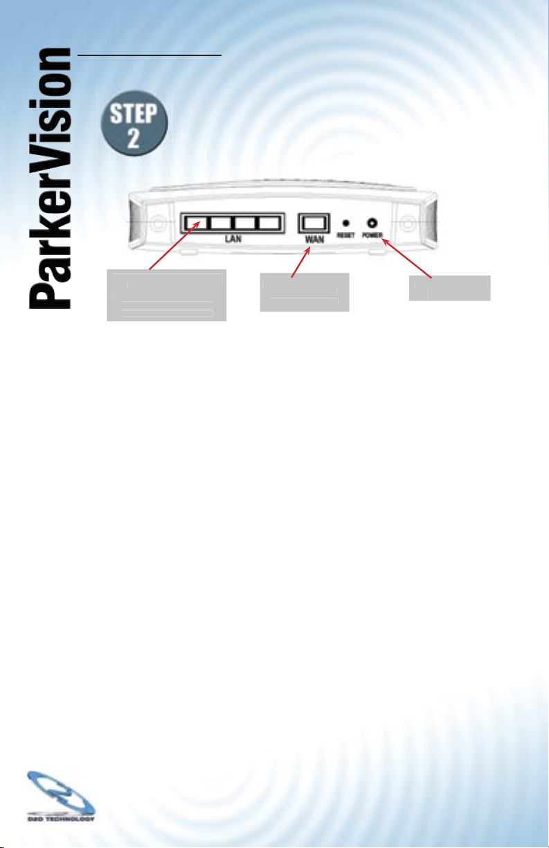
Plug the AC Adapter
into this port.
Plug your computer’s Ethernet
cable into Port 1. The
remaining ports can to be used
with other computers in a
hard-wired router fashion.
Plug your cable or DSL
modem’s Ethernet
Cable into this port.
WR1500 4-Port Wireless DSL/Cable Router
Make the connections
as described below.
The rear panel of the WR1500 contains several ports,
as shown:
For initial setup, you should have:
• The power adapter plugged into the WR1500 as shown, and
this adapter plugged into a surge-protected electrical outlet.
7
• Your Cable or DSL modem’s Ethernet cable plugged into the
Internet-In port as shown above.
• An Ethernet cable plugged into the router port 1 as shown above,
and the other end of this cable plugged into your computer’s
Ethernet port.
Proceed to the Next Page to Begin Setting Up Your WR1500.
Page 7
®
8
WR1500 4-Port Wireless DSL/Cable Router
Establishing Contact on Your Computer
with the WR1500.
Once you have made all of the connections shown in the
previous step, complete the following steps, which will allow
you to confi gure the WR1500 using the Web Confi guration
Utility. The Web Confi guration Utility makes it easy to
confi gure and manage the WR1500 Wireless Router.
Accessing the WR1500 Wireless
Router Web Configuration Utility.
Step 3.1 Make sure your WR1500 Wireless Router hardware is
properly connected.
Step 3.2 Prepare your computer to connect to the WR1500
Wireless Router, if it is not powered on, boot it up
and log in.
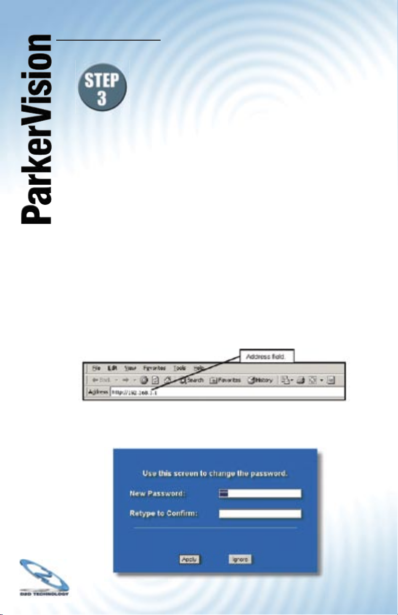
Step 3.3 Launch your web browser.
Step 3.4 Type “http://192.168.1.1” as the URL Address fi eld.
Step 3.5 Type “1234” (default) as the password and click Login.
In some versions, the default password appears
automatically - if this is the case, click Login.
Step 3.6 You should see a screen asking you to change your
password (highly recommended) as shown next. Type a
new password (and retype it to confi rm) and click Apply or
click Ignore to allow access without password change.
Continued next page
Page 8

®
WR1500 4-Port Wireless DSL/Cable Router
Note - If the default password of “1234” is not accepted, refer to
page 17 of this guide and go through the reset procedure to set
all parameters back to factory defaults. Then try the above steps
again.
If you do not see the log-in window, go back and double check that
the WR1500 is powered on, and that the Ethernet Cable between
it and your computer is plugged in securely. If, after checking these
items, you still cannot make contact with the WR1500, you may want
to try a different Ethernet Cable. Also, refer to the troubleshooting
section in the appendix of this quick start guide. If you still have
diffi culty with installation, contact support at 800-231-1759 or
support@direct2data.com.
9
Page 9
®
10
Establishing Contact on Your Computer
with the WR1500 - Continued
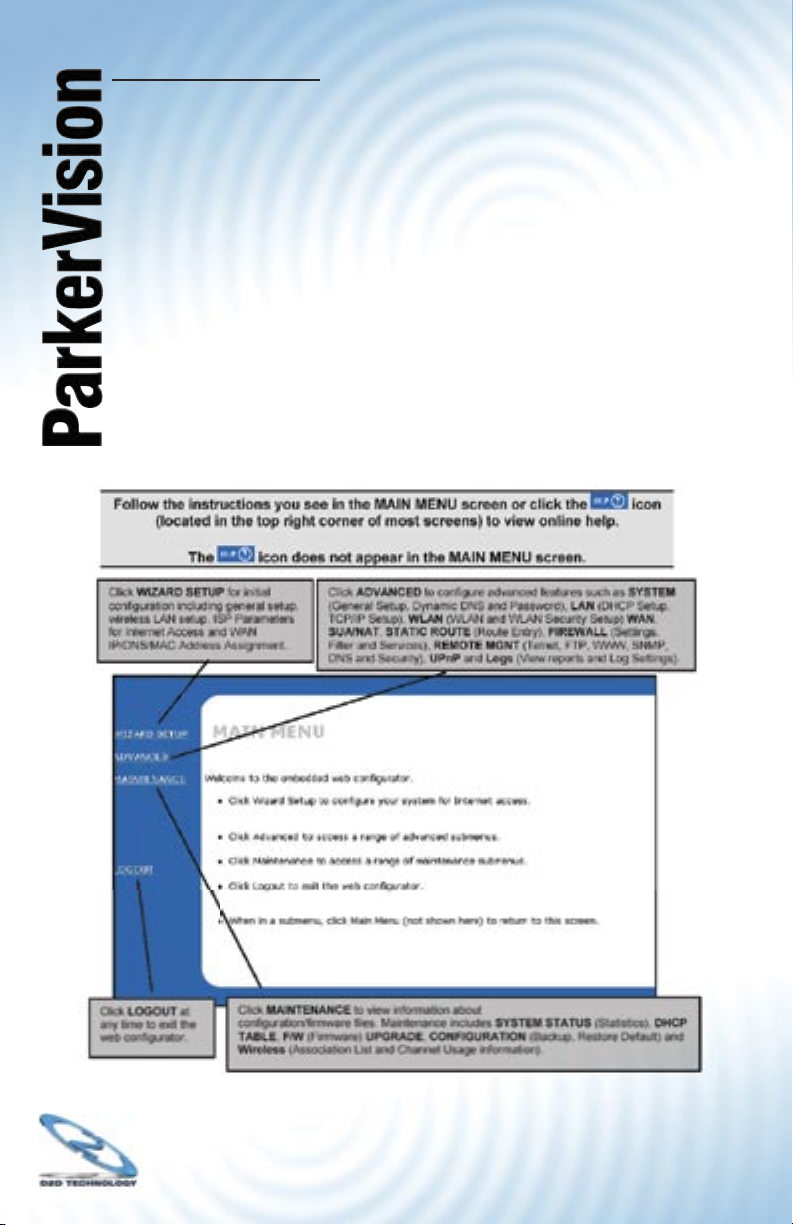
Step 3.7 You should now see the MAIN MENU screen,
as shown below.
Note - The WR1500 Wireless Router automatically times out after
fi ve minutes of inactivity. Simply log back into the WR1500 Wireless
Router if this happens to you.
Note - If you forget your password or cannot access the WR1500,
you will need to reset the unit. Refer to the section on resetting the
unit in the appendix of this quick start guide.
Page 10

®
Wizard Setup: General Setup
General Setup
contains administrative and
system-related information.
The following table describes the labels in the Wizard Setup screen.
WR1500 4-Port Wireless DSL/Cable Router
WIZARD
General Setup:
This information is optional, but may be helpful in accessing services of your Internet Service
Provider, such as mail and news servers and customer support web pages.
Enter a descriptive name for identification purposes. We recommend using your computer’s name.
System Name:
The ISP’s domain name is often sent automatically by the ISP to the router. If you are having
difficulty accessing ISP services, you may need to enter the Domain Name manually in the field
below.
11
Domain Name:
direct2data.com
Continued next page
Page 11

®
Wizard Setup: Wireless LAN Setup - Continued
Set up your wireless LAN using the wizard screen below.
WIZARD
Wireless LAN Setup
12
ESSID
Choose Channel ID
WEP Encryption
64-bit WEP: Enter 5 ASCII characters or 10 hexadecimal characters (”0-9”, “A-F”) for each Key (1-4).
128-bit WEP: Enter 13 ASCII characters or 26 hexadecimal characters (”0-9”, “A-F”) for each Key (1-4).
Select one WEP key as an active key to encrypt wireless data transmission
Key 1
Key 2
Key 3
Key 4
Wireless
Channel-06 2437MHz
Disable
ASCII Hex
or
Scan
Back Next
The table on the following page describes the labels in the Wizard
Setup screen shown above.
Continued next page
Page 12

®
DESCRIPTION
ASCII characters) for the wireless LAN.
wireless network.
Scan
with the least interference.
ASCII
ASCII characters or 26 hexadecimal characters
You must confi gure all four keys, but only one key
WR1500 4-Port Wireless DSL/Cable Router
13
Continued next page
Page 13

®
You must choose the
when the WAN port is used as a regular
14
WIZARD
ISP Parameters for Internet Access
Encapsulation
Service Type
User Name
Password
Login Server IP Address
Ethernet
RR-Toshiba
0.0.0.0
Back Next
Continued next page
Page 14

®
Address
WR1500 4-Port Wireless DSL/Cable Router
15
Page 15

®
PPTP Encapsulation
Point-to-Point Tunneling Protocol (PPTP) is a network protocol that
enables transfers of data from a remote client to a private server,
creating a Virtual Private Network (VPN) using TCP/IP-based
networks.
PPTP supports on-demand, multi-protocol, and virtual private
networking over public networks, such as the Internet.
Refer to the manual on the CD ROM for more information on PPTP.
The WR1500 Wireless Router supports one PPTP server
connection at any given time.
WIZARD
ISP Parameters for Internet Access
16
Encapsulation
User Name
Password
Nailed-Up Connection
Idle Timeout
PPTP Configuration
My IP Address
My IP Subnet Mask
Server IP Address
Connection ID/Name
PPTP
100 (In Seconds)
10.0.0.140
0.0.0.0
10.0.0.138
Back Next
Continued next page
Page 16

®
want the connection to time out.
WR1500 4-Port Wireless DSL/Cable Router
17
Continued next page
Page 17

®
PPPoE Encapsulation
Point-to-Point Protocol over Ethernet (PPPoE) functions as a
dial-up connection. PPPoE is an IETF (Internet Engineering Task
Force) draft standard specifying how a host personal computer
interacts with a broadband modem (for example xDSL, cable,
wireless, etc.) to achieve access to high-speed data networks. It
preserves the existing Microsoft Dial-Up Networking experience
and requires no new learning or procedures.
For the service provider, PPPoE offers an access and authentication
method that works with existing access control systems (for instance,
RADIUS). For the user, PPPoE provides a login and authentication
method that the existing Microsoft Dial-Up Networking software can
activate, and therefore requires no new learning or procedures for
Windows users.
One of the benefi ts of PPPoE is the ability to let end users access
one of multiple network services, a function known as dynamic
service selection. This enables the service provider to easily create
and offer new IP services for specifi c users.
18
Operationally, PPPoE saves signifi cant effort for both the subscriber
and the ISP/carrier, as it requires no specifi c confi guration of the
broadband modem at the subscriber’s site.
By implementing PPPoE directly on the WR1500 Wireless Router
(rather than individual computers), the computers on the LAN do not
need PPPoE software installed, since the WR1500 Wireless Router
does that part of the task. Furthermore, with NAT, all of the LAN’s
computers will have Internet access.
Refer to the manual on the CD ROM for more information on
PPPoE, and to the next page for setup details.
Continued next page
Page 18

®
WR1500 4-Port Wireless DSL/Cable Router
WIZARD
ISP Parameters for Internet Access
19
Encapsulation
Service Name
User Name
Password
Nailed-Up Connection
Idle Timeout
PPP over Ethernet
100
(In Seconds)
Back Next
Page 19

®
20
Wizard Setup: WAN and DNS
The fourth wizard screen allows you to confi gure WAN IP address
assignment, DNS server address assignment and the WAN MAC
address.
WAN IP Address Assignment
Every computer on the Internet must have a unique IP address. If
your networks are isolated from the Internet, for instance, only
between your two branch offi ces, you can assign any IP addresses
to the hosts without problems. However, the Internet Assigned
Numbers Authority (IANA) has reserved the following three blocks of
IP addresses specifi cally for private networks.
10.0.0.0 - 10.255.255.255
172.16.0.0 - 172.31.255.255
192.168.0.0 - 192.168.255.255
You can obtain your IP address from the IANA, from an ISP or have
it assigned by a private network. If you belong to a small organization and your Internet access is through an ISP, the ISP can provide
you with the Internet addresses for your local networks. On the other
hand, if you are part of a much larger organization, you should
consult your network administrator for the appropriate IP addresses.
Regardless of your particular situation, do not create an
arbitrary IP address; always follow the guidelines above. For
more information on address assignment, please refer to RFC
1597, Address Allocation for Private Internets and RFC 1466,
Guidelines for Management of IP Address Space.
Continued next page
Page 20

®
21
WR1500 4-Port Wireless DSL/Cable Router
IP Address and Subnet Mask
Similar to the way houses on a street share a common street name,
so too do computers on a LAN share one common network number.
Where you obtain your network number depends on your particular
situation. If the ISP or your network administrator assigns you a block
of registered IP addresses, follow their instructions in selecting the IP
addresses and the subnet mask.
If the ISP did not explicitly give you an IP network number, then most
likely you have a single user account and the ISP will assign you
a dynamic IP address when the connection is established. If this is
the case, it is recommended that you select a network number from
192.168.0.0 to 192.168.255.0 and you must enable the Network
Address Translation (NAT) feature of the WR1500 Wireless Router.
The Internet Assigned Number Authority (IANA) reserved this block
of addresses specifi cally for private use; please do not use any
other number unless you are told otherwise. Let’s say you select
192.168.1.0 as the network number; which covers 254 individual
addresses, from 192.168.1.1 to 192.168.1.254 (zero and 255 are
reserved). In other words, the fi rst three numbers specify the network
number while the last number identifi es an individual computer on
that network.
Once you have decided on the network number, pick an IP address
that is easy to remember, for instance, 192.168.1.1, for your WR1500
Wireless Router, but make sure that no other device on your network
is using that IP address.
The subnet mask specifi es the network number portion of an IP
address. Your WR1500 Wireless Router will compute the subnet
mask automatically based on the IP address that you entered. You
don’t need to change the subnet mask computed by the WR1500
Wireless Router unless you are instructed to do otherwise.
Page 21

®
22
DNS Server Address Assignment
Use DNS (Domain Name System) to map a domain name to its corresponding IP address and vice versa. For instance, the IP address of
a web site with an URL of www.anycompany.com could be 192.168.3.1.
The DNS server is extremely important because without it, you must
know the IP address of a computer before you can access it.
There are two ways that an ISP disseminates
the DNS server addresses.
1. The ISP tells you the DNS server addresses, usually in the
form of an information sheet, when you sign up. If your ISP
gives you DNS server addresses, enter them in the DNS
Server fi elds in DHCP Setup.
2. Leave the DNS Server fi elds in DHCP Setup blank
(for example 0.0.0.0). The WR1500 Access Point acts as a
DNS proxy when this fi eld is blank.
WAN MAC Address
Every Ethernet device has a unique MAC (Media Access Control)
address. The MAC address is assigned at the factory and consists of
six pairs of hexadecimal characters, for example, 00:A0:C5:00:00:02.
You can confi gure the WAN port’s MAC address by either using the
factory default or cloning the MAC address from a workstation on your
LAN. Once it is successfully confi gured, the address will be copied to the
“rom” fi le (factory confi guration fi le). It will not change unless you change
the setting or upload a different “rom” fi le.
ParkerVision recommends you clone the MAC address from a workstation on your LAN even if your ISP does not require MAC address
authentication.
Your WR1500 Wireless Router WAN port is always set at half-duplex
mode as most cable/DSL modems only support half-duplex mode. Make
sure your modem is in half-duplex mode. Your WR1500 Wireless Router
supports full duplex mode on the LAN side.
Continued next page
Page 22

®
Addresses:
WR1500 4-Port Wireless DSL/Cable Router
WAN MAC Address - Continued
WIZARD
WAN IP Address Assignment
Get automatically from ISP (Default)
Use fixed IP Address
23
My WAN IP Address
My WAN IP Subnet Mask
Gateway IP Address
DNS Server Address Assignment
0.0.0.0
0.0.0.0
0.0.0.0
Get automatically from ISP (Default)
Use fixed IP Address - DNS Server IP Address
Primary DNS Server
Secondary DNS Server
WAN MAC Address
Factory default
Spoof this computer’s MAC Address
- IP Address
0.0.0.0
0.0.0.0
192.168.1.36
Back Next
The table on the following page describes the labels
in the screen above.
Continued next page
Page 23

®
24
Page 24

®
25
WR1500 4-Port Wireless DSL/Cable Router
The Basic Setup of Your WR1500 is
Now Complete
Click Finish to complete and save the wizard setup.
If you are currently using a wireless (LAN) adapter to
access this ParkerVision Router/Wireless Router and
you made changes to the ESSID, then you will need to
make the same change to your wireless (LAN) adapter
after you click the Finish button.
Your WR1500 should now be operational. There
are many additional confi gurations that can be set.
Complete details of how to confi gure these options are
in the manual, on the CD-ROM.
Saving and Restoring Your Configuration
It is important that you now save your confi guration fi le in case you
ever need to reset your WR1500, so you can easily restore your
confi guration settings.
Follow the steps below to save your confi guration.
1. From the Main Menu, choose Maintenance, then Confi guration,
then Backup.
2. You will be presented with the option to save the confi guration
fi le on your computer’s hard drive. It is important that you choose
a location that you will be able to locate later.
3. Logout of the Main Menu.
Note - It is important to always logout when you are fi nished using
the Web Confi guration Utility.
Page 25

®
26
Appendix 1 - How to Reset the WR1500
Resetting the WR1500 Wireless Router
If you forget your password or cannot access the WR1500 Wireless
Router, you will need to reload the factory-default confi guration
fi le or use the RESET button on the rear panel of the WR1500
Wireless Router. Uploading this confi guration fi le replaces the current
confi guration fi le with the factory-default confi guration fi le. This means
that you will lose all confi gurations that you had previously and the
speed of the console port will be reset to the default of 9600bps with
8 data bit, no parity, one stop bit and fl ow control set to none. The
password will be reset to “1234”, also.
Use the tip of a pen or some
other non-sharp object to
depress the reset button.
Procedure to Use the Reset Button
Make sure the SYS LED is on (not blinking) before you begin this
procedure.
Step 1. Press the RESET button for more than fi ve seconds, and
then release it. If the SYS LED begins to blink, the
defaults have been restored and the WR1500 Wireless
Router restarts. Otherwise, go to step 2.
Step 2. Turn the WR1500 Wireless Router off.
Step 3. While pressing the RESET button, turn the WR1500
Wireless Router on.
Step 4. Continue to hold the RESET button. The SYS LED will
begin to blink and fl icker very quickly after about 10 or 15
seconds.This indicates that the defaults have been
restored and the WR1500 Wireless Router is now
restarting.
Step 5. Release the RESET button and wait for the WR1500
Wireless Router to fi nish restarting.
Continued next page
Page 26

®
Appendix 2 - Troubleshooting the WR1500 Initial
Access Point via
27
WR1500 4-Port Wireless DSL/Cable Router
Continued next page
Page 27

®
28
Appendix 2 - Troubleshooting the WR1500 Initial
Setup and Installation - Continued
Continued next page
Page 28

®
Appendix 2 -
Access
29
WR1500 4-Port Wireless DSL/Cable Router
Continued next page
Page 29

®
Appendix 2 -
You can also request help by sending an email to
30
 Loading...