

Parker Pneumatic CC12, CC10 Service Manual

Pneumatic Division North America
Richland, Michigan 49083
Installation & Service Instructions
V-287BP
CC10 & CC12 Series Valves
ISSUED: August, 2000
Supersedes: April, 2000
ECN# P27805
WARNING
!
To avoid unpredictable system behavior that can cause personal injury
and property damage:
• Disconnect electrical supply (when necessary) before installation,
servicing, or conversion.
• Disconnect air supply and depressurize all air lines connected to
this product before installation, servicing, or conversion.
• Operate within the manufacturer’s specified pressure, temperature,
and other conditions listed in these instructions.
• Medium must be moisture-free if ambient temperature is below
freezing.
• Service according to procedures listed in these instructions.
• Installation, service, and conversion of these products must be
performed by knowledgeable personnel who understand how
pneumatic products are to be applied.
• After installation, servicing, or conversion, air and electrical
supplies (when necessary) should be connected and the product
tested for proper function and leakage. If audible leakage is present,
or the product does not operate properly, do not put into use.
• Warnings and specifications on the product should not be covered
by paint, etc. If masking is not possible, contact your local
representative for replacement labels.
Air Leakage Through Exhaust Ports
1. Check center spool seals for nicked, cracked, peeled and / or
delamination.
2. Check for missing, damaged, swollen or incorrectly assembled
O-rings and gaskets.
3. Check stem guides and body bore for nicks, scratches and
dirt par ticles.
4. Check body to base gaskets for damage or improper assembly.
Note: If valve unit is equipped with sandwich flow control, these
similar looking base gaskets may be positioned improperly.
Introduction
Follow these instructions when installing, operating, or servicing
the product.
Application Limits
These products are intended for use in general purpose
compressed air systems only.
Operating Inlet Pressure: kPa psig bar
Maximum 1034 150 10.34
Also suitable for vacuum service.
Pilot pressure is 30 to 150 PSIG.
Ambient Temperature Range: -18°C to 71°C (0°F to 160°F)
A
ssembly Instructions
These products are intended for use in general purpose
compressed air systems only.
1. Valve is subbase mounted. All air connections are to the
subbase and remote pilot actuating heads. With removal of
the pipe connection to the actuating heads, the valve body
can be easily removed without disturbing the piping to the
subbase.
2. Cylinder exhaust can be controlled by installing the Sandwich
Flow Control section between the valve body and base. See
Maintenance Bulletin V-241BP for detailed information.
3. Remote pilot pressure should be 30 to 150 PSIG (2.1 to 10
bar).
4. Filtered and lubricated air is necessary for maximum valve life
and minimum maintenance.
WARNING
!
FAILURE OR IMPROPER SELECTION OR IMPROPER USE OF
THE PRODUCTS AND/OR SYSTEMS DESCRIBED HEREIN OR
RELATED ITEMS CAN CAUSE DEATH, PERSONAL INJURY AND
PROPERTY DAMAGE.
This document and other information from Parker Hannifin Corporation,
its subsidiaries and authorized distributors provide product and/or
system options for further investigation by users having technical
expertise. It is important that you analyze all aspects of your application,
including consequences of any failure and review the information
concerning the product or systems in the current product catalog. Due
to the variety of operating conditions and applications for these products
or systems, the user, through its own analysis and testing, is solely
responsible for making the final selection of the products and systems
and assuring that all performance, safety and warning requirements
of the application are met.
The products described herein, including without limitation, product
features, specifications, designs, availability and pricing, are subject
to change by Parker Hannifin Corporation and its subsidiaries at any
time without notice.
EXTRA COPIES OF THESE INSTRUCTIONS ARE AVAILABLE FOR
INCLUSION IN EQUIPMENT / MAINTENANCE MANUALS THAT UTILIZE
THESE PRODUCTS. CONTACT YOUR LOCAL REPRESENTATIVE.
CC10 & CC12 Series Valves V-287BP
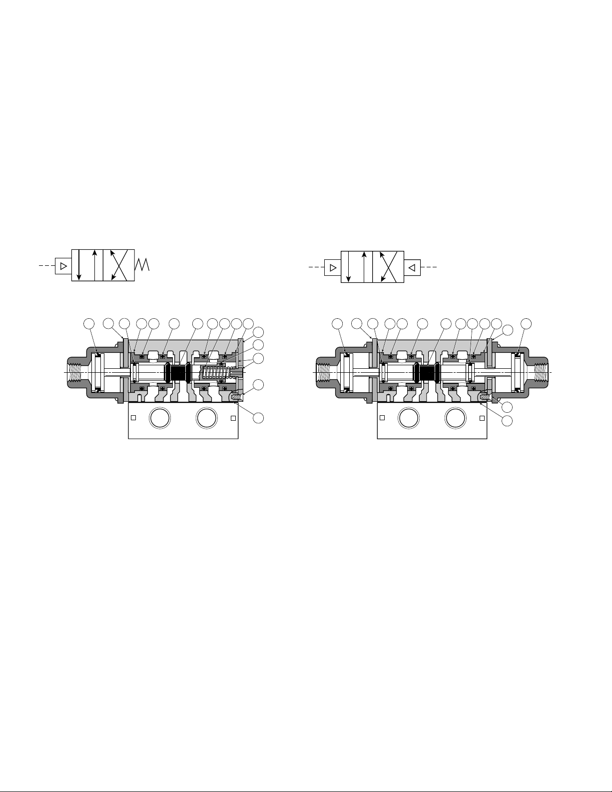
Valve Body Service Procedures
1. Turn off air supply and bleed off trapped pressure in the valve.
2. Remove the actuator(s) from the B-02 end (and A-01 end for
CC122).
3. Remove end plates (Items 5 & 10), spring guide / spool stop
assembly (Item 6) (CC10 only), return spring (Item 2) (CC10
only), Spool (Item 1) and stem guides (Item 4) .
4. Thoroughly clean the valve body bore and stem guides and inspect
for possible nicks, scratches and material imperfections.
5. Lightly lubricate the spool seals (Item 7). Replace and lubricate
stem guide seals (Item 3). (Use a nondetergent hydro-carbon
base oil or grease.)
6. Inser t new spool (Item 1) and return spring (Item 2) (CC10 only)
from the service kit into the body. Spring return end of valve is
7. Install the stem guides (Items 4) to both ends. Install spring guide
/ spool stop assembly (Item 6) to A-01 end (CC-10 only).
Note: The larger of the two protruding hubs of the spring guide /
spool stop assembly (CC10 only) is towards the outside of
the body.
8. Attach end plates (Items 5 & 10) (CC10 only), (Item 5) (CC10) to
valve body with screws (Item 8). Tighten to 1.1 to 1.4 Nm (10 to
12 in. lb.) torque. If body is removed from base, tighten screws to
11.2 to 14.1 Nm (100 to 125 in. lb.) torque.
9. Replace lipseal (Item 11) in each actuator. Lightly lubricate seal.
10. Replace actuator(s). Tighten screws to 1.1 to 1.4 Nm (10 to
12 in. lb.) torque.
11. Turn on air supply. Check valve for proper function; and internal
and external air leakage.
A-01. If valve is off base, A-01 end is the end of the body with a
machined locating hole in the body to base surface of the body.
01
02
02
01
BA
10
1 427 411 3333
5
7
6
8
AB
9
CC10 - Single Remote Pilot CC12 - Double Remote Pilot
Valve Body Service Kit
Consisting of items: 1, 2, 3, 7, 8, 9 & 11..................... PL503400
BA
5
1 47 411 1137333
5
8
AB
9
Valve Body Service Kit
Consisting of items: 1, 3, 7, 8, 9, & 11 ........................ PL503500
 Loading...