

Parker Hydraulics PGM 300, PGP315, PGP 300, PGP330, PGM315 Service Manual
...
Service Manual HY09-SM300/US
Service Manual
PGP/PGM315, 330, 350, 365
Effective: April 15, 2002
Supersedes: July 1, 1998
PGP/PGM 300 Series
PGP/PGM 300 Series
Service Manual HY09-SM300/US
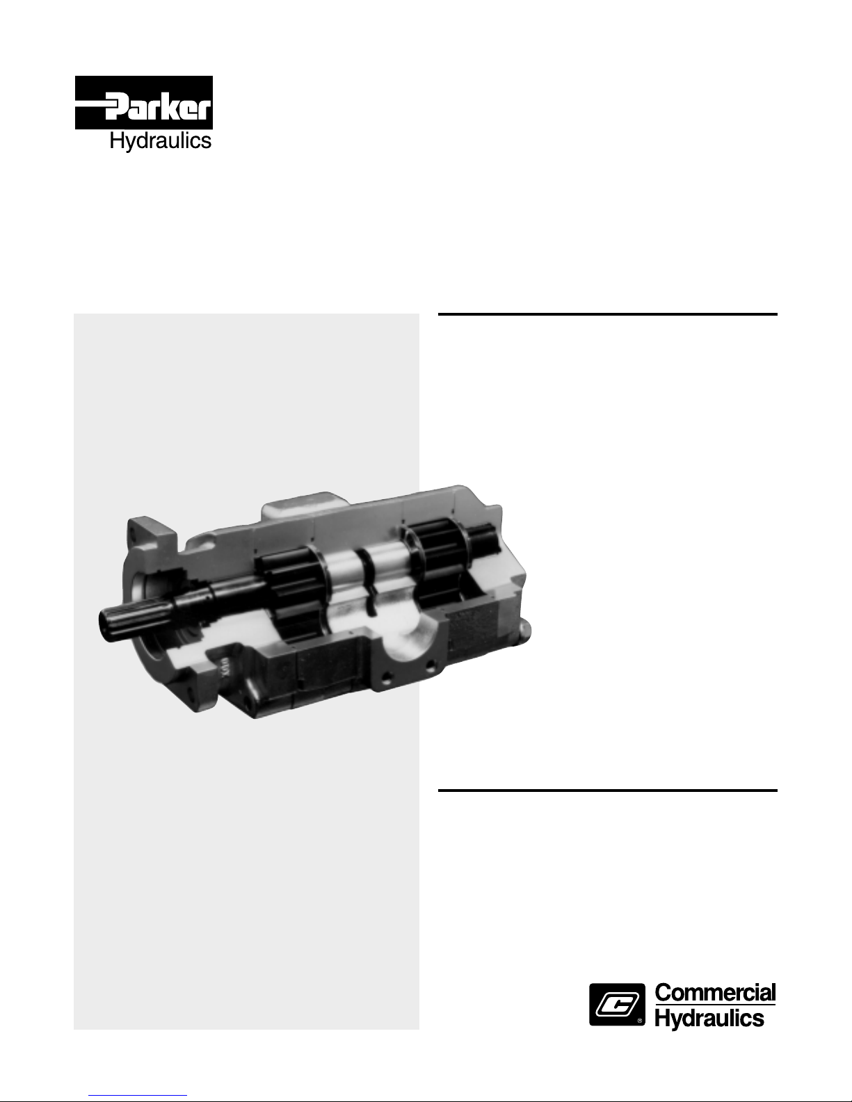
Single Pump
Split-flange or ODT
Ports
High Temperature
Cast Iron
Housings
Case Hardened Gears
Seals
Low-friction
Bushing Coating
SAE 2- or 4-Bolt
Mountings
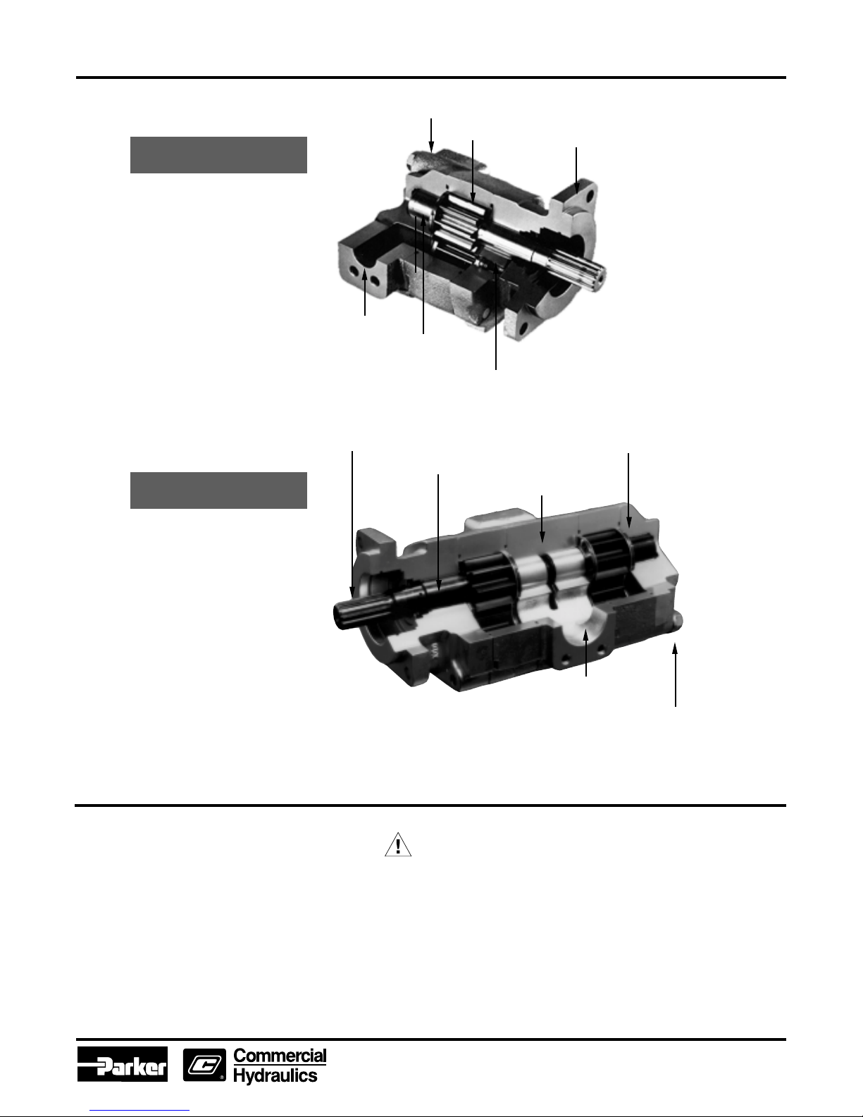
Multiple Pump
One-piece Drive
Shaft & Gear
Long Shaft Journals Superior
Bearing Surface
Internal Passage Constantly
Lubricates Bushings
Balanced Thrust Plates
Minimize Friction and Leakage
Large Passages for
Better Pump Feed
Extended Studs
Available for Mounting
Support
Use Genuine Parker Replacement parts
Legal Notification
FAILURE OR IMPROPER SELECTION OR IMPROPER USE OF THE PRODUCTS AND/OR SYSTEMS DESCRIBED HEREIN OR RELATED ITEMS CAN CAUSE DEATH, PERSONAL
INJURY AND PROPERTY DAMAGE.
This document and other information from Parker Hannifin Corporation, its subsidiaries and authorized distributors provide product and/or system options for further investigation by users
having technical expertise. It is important that you analyze all aspects of your application and review the information concerning the product or system in the current product catalog. Due
to the variety of operating conditions and applications for these products or systems, the user, through its own analysis and testing, is solely responsible for making the final selection of
the products and systems and assuring that all performance, safety and warning requirements of the application are met.
The products described herein, including without limitation, product features, specifications, designs, availability and pricing, are subject to change by Parker Hannifin Corporation and its
subsidiaries at any time without notice.
The items described in this document are hereby offered for sale by Parker Hannifin Corporation, its subsidiaries or its authorized distributors. This offer and its acceptance are governed
by the provisions stated in the “Offer of Sale”.
© Copyright 2002, Parker Hannifin Corporation, All Rights Reserved.
WARNING
Offer of Sale
2
Parker Hannifin Corporation
Gear Pump Division
Youngstown, OH
315/330/350/365
Service Manual
General Instructions
These service instructions will familiarize you with
Parker's single and multiple pumps
• their component parts
• the relative position of each part
• proper methods for assembly or disassembly of
the units
To facilitate the repair of these units and before any
work is done, we suggest that you first read all of the
steps used in disassembly and assembly.
Dirt is the enemy of any hydraulic system. The first
requirement for good maintenance of hydraulic
equipment is cleanliness. MAKE SURE YOU
DISASSEMBLE AND ASSEMBLE YOUR
HYDRAULIC EQUIPMENT IN A CLEAN AREA.
PGP/PGM 300 Series
Service Manual HY09-SM300/US
The pictures show Model PGP365. Notes in the
text cover variations between this unit and the
other models.
It is important to airblast all parts and wipe them with
a clean, lintless cloth before assembly.
USE CAUTION IN GRIPPING ALL PARTS
IN THE VISE TO AVOID DAMAGING
MACHINED SURFACES.
A pump must be driven in the direction of rotation for
which it was built; otherwise, pressure will blow the
shaft seal. Check the exploded view and notes at right
for proper direction of rotation.
Parker's
Replacement Parts
Parker's replacement parts are of original equipment
standards. For assured quality of material and workmanship, and for compatibility in assembly, USE
ONLY GENUINE PARTS.
Check all replacement parts before installing them to
be certain that they were not damaged in shipment.
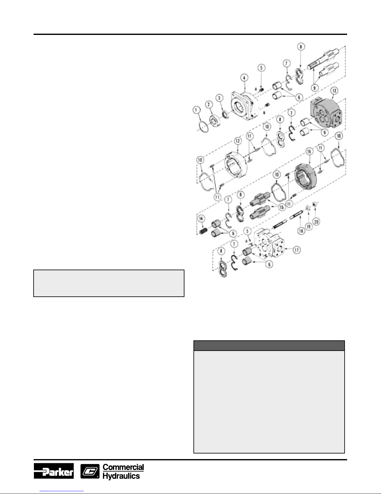
Items shaded apply to
multiple assemblies only.
NOTE:
For PGP315 and PGP330 ONLY - Plug 5
required in position A and position B.
For PGP350 and PGP365 ONLY - Plug 5 in
position B gives clockwise rotation. Plug 5 in
position A gives counterclockwise rotation.
PARTS LIST
1. Snap Ring
2. Outboard Bearing
3. Seal
4. Shaft End Cover
5. Plug
6. Bushings
7. Channel Seal
8. Thrust Plates
9. Integral Drive Shaft
and Gear Set
10. Gasket Seal
11. Dowel Pins (Solid for
PGP/PGM 315, 330 and
350. Hollow for PGP/PGM
365 ONLY.)
12. Gear Housing
13. Bearing Carrier
14. Connecting Shaft
15. Matched Gear Set
16. Gear Housing
17. Port End Cover
18. Studs or Cap Screws
19. Washers
20. Nuts
3
Parker Hannifin Corporation
Gear Pump Division
Youngstown, OH
PGP/PGM 300 Series
Service Manual HY09-SM300/US
Tool List
• Arbor press
• Awl
• 1 1/2" Dia. steel ball
• Bearing puller (Owatonna Tool Co.
M D - 956 or equivalent)
• Bushing remover tool (See A)
• Clean, lintless cloths
• Deburring tool (an old file with
cutting teeth ground off)
• Machinist's hammer
• Soft hammer
• Permatex Aviation Form-A-Gasket
No. 3 non-hardening sealant or equivalent
• Medium grit carborundurn stone
• Seal removal tool (See B)
• Oil and grease
• Snap ring pliers
• Prick punch
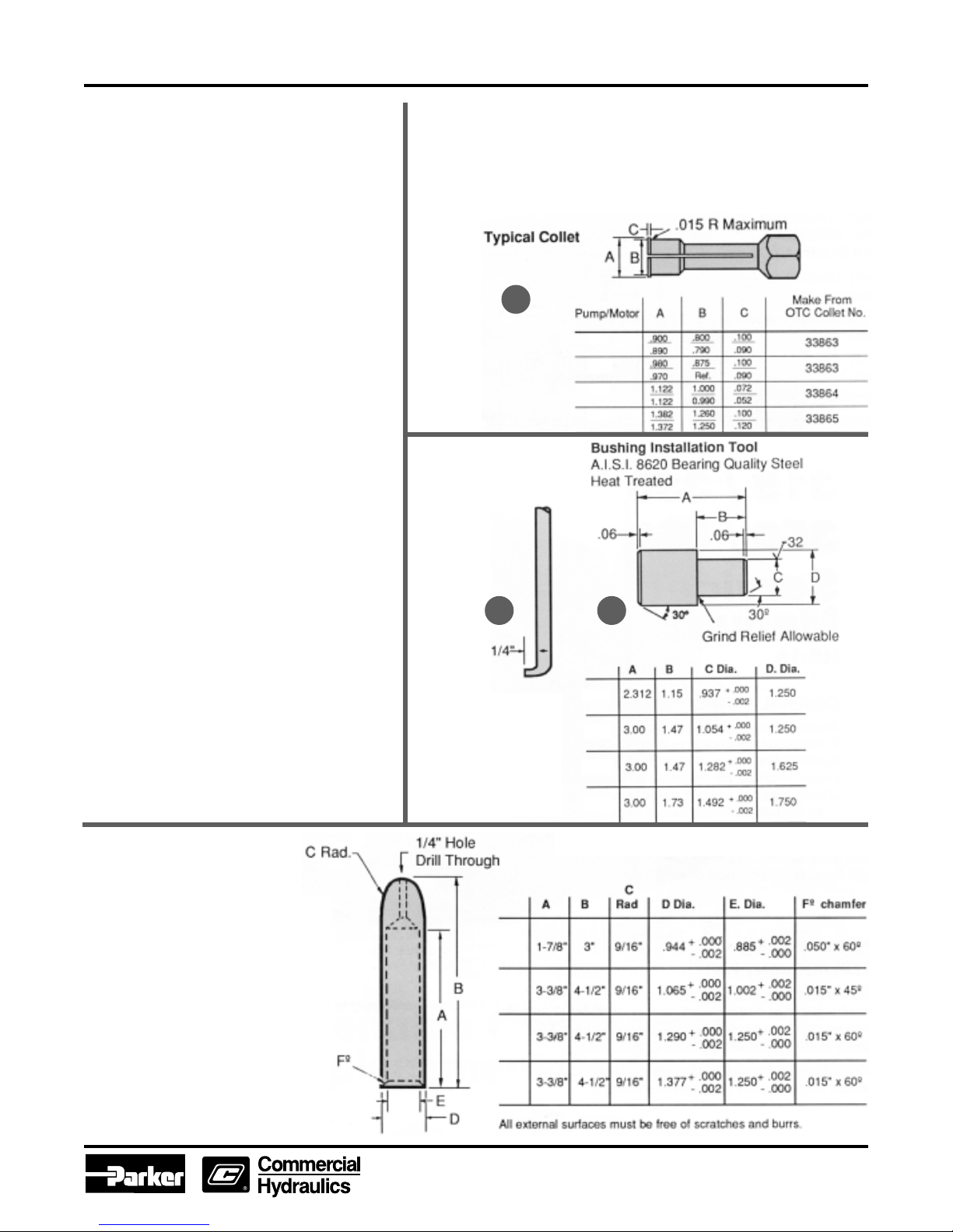
• Bushing installation tool (See C)
• Scale ( 1/32" or 1/64" graduations)
• Small screw driver
• Torque wrench
• Vise with 6" minimum opening.
•
Bar for lip seal installation
Note: For PGP/PGM315 use 1 5/8" dia. x 2" bar.
For PGP/PGM330 use 1 3/4" d ia. x 2" bar.
For PGP/PGM350 use 2 1/2" dia. x 2" bar
For PGP/PGM365 use 2 1/2" dia. x 2" bar.
• Special steel sleeve ( see sketch )
TM
Bushing Puller: The bushings in
PGP/PGM
315, 330, 350 and 365
pumps may be removed from their bores, using blind hole collet-type
bushing pullers similar to those manuf actured b y Ow atonna Tool Co .
The table below illustrates the modifications necessary to adapt the
OTC collets to this task. Equivalent pullers from other suppliers may
be modified in similar fashion.
A
PGP/PGM
315
PGP/PGM
330
PGP/PGM
350
B
Seal Removal Tool
Easily made from an
old screw driver. Heat
the tip and bend as
shown. Grind the tip
to fit the notch behind
the shaft seal.
C
PGP/PGM
315
PGP/PGM
330
PGP/PGM
350
PGP/PGM
365
Special Steel Sleeve
The special steel sleeve is
used to insert the drive shaft
through the lip seal without
damage and can be made
from bar stock: For the
PGM
315 use a 1 " dia. x 3-1/
8" bar; for the
PGP/PGM
PGP/
330
use a 1-1/8" or 1-1/4" dia. x
4- 5/8" bar; for the
PGM
350 use a 1-3/8" dia. x
4-5/8" bar; for the
PGM
365 use a 1- 1 /2" dia. x
PGP/
PGP/
4-5/8" bar. The drawing and
chart give details for making
this special tool.
PGP/PGM
315
PGP/PGM
330
PGP/PGM
350
PGP/PGM
365
4
Parker Hannifin Corporation
Gear Pump Division
Youngstown, OH
PGP/PGM 300 Series
Service Manual HY09-SM300/US
Start Disassembly Here
CAUTION:
1. If prying off sections becomes necessary, take extreme care not to mar or damage machined surfaces. Excessive force while prying
can result in misalignment and seriously damage parts.
2. If parts are difficult to fit during assembly , tap gently with a soft hammer (ne ver use an iron hammer).
3. Gears are closely matched, therefore the y must be k ept together as sets when remov ed from a unit. Handle with care to a voi d
damage to the journals or teeth. Avoid touching gear journals.
4. Ne ver hammer b ushings into bores; use an arbor press.
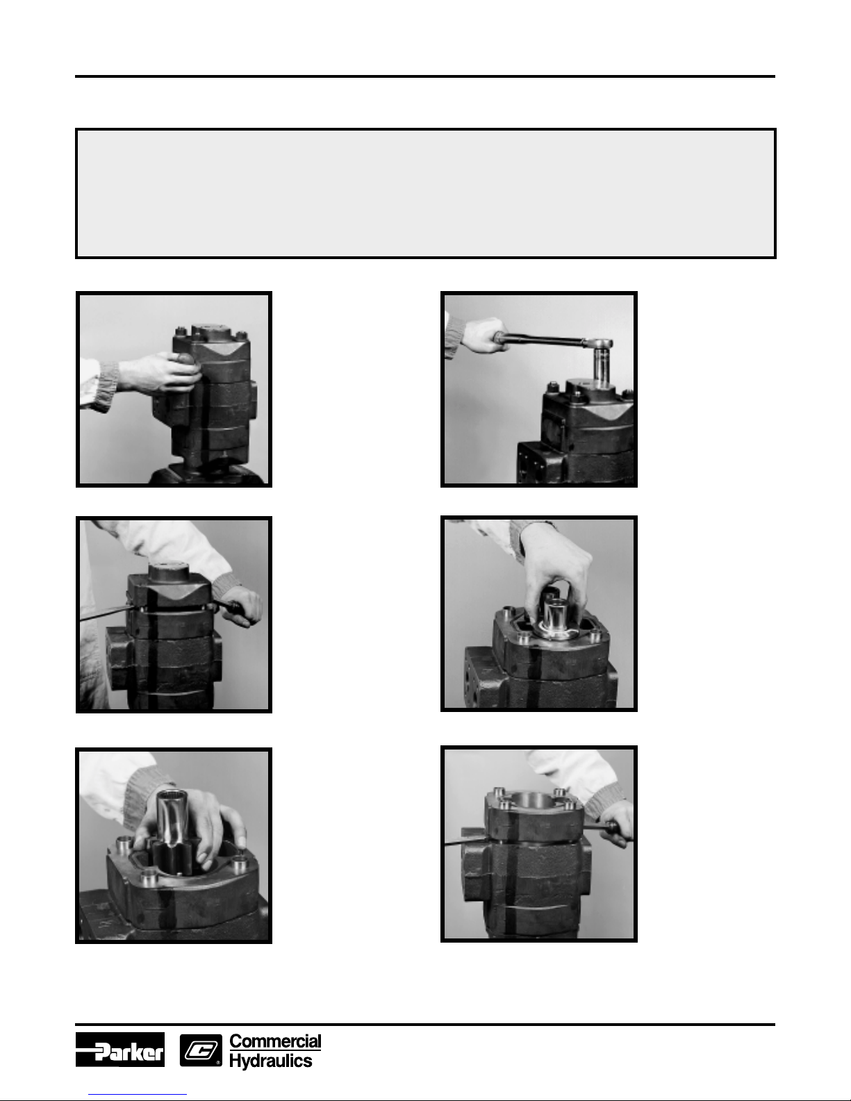
1) Place the pump in a
vise with the drive shaft
pointIng down. Caution:
DO NOT GRIP ON OR
NEAR ANY MACHINED
SURFACES DURING
ASSEMBLY OR
DISASSEMBLY.
Match-mark all sections.
Be sure to align these
marks when
reassembling.
3) Lift off the port end
cover. If prying is
necessary, be careful not
to damage the machined
surfaces. Dowel pins will
remain in either the port
end cover or the gear
housing.
2) Use a socket wrench
to remove the 4 cap
screws on single units or
the 4 hex nuts, studs
and washers of multiple
units.
4) Remove the thrust
plate. Examine and
replace if necessary.
See wear guide page 10.
5) Carefully remove the
drive and driven gears.
Avoid tapping the gear teeth
together or against other
hardened surfaces. Keep
these gears together
because they are a matched
set. Examine and replace if
necessary. (See page 10).
Remove the thrust plate
from the bearing carrier.
Examine and replace if
necessary.
For multiple assemblies only
6) Lift the gear housing
from the bearing carrier.
If prying is necessary,
take care not to damage
machined surfaces.
Examine and replace
if necessary.
(See page 10)
For multiple assemblies
only
5
Parker Hannifin Corporation
Gear Pump Division
Youngstown, OH
 Loading...