

Page 1

p/n 88-019933-01 A
G
e
m
A
utomation
ini
G
e
m
ini
C
o
mmand
Effective: October 1, 2001
GV6K
GT6K
R
eference
a
nd
F
N
I
R
I
D
T
GF
R
T
W
AR
ST
SF
A
T
H
RR
E
GOW
NC
IT
A
O
O
H
LI
N
TP
M
R
E
O
R
N
U
M
E
E
TF
NC
F
TPE
RA
E
AD
TST
TI
NC
D
EF
D
SE
NCCN
M
T
A
TFSF
N
LS
A
L
EL
D
T
A
TIO
C
H
PS
ND
E
OY
J
FOL
KA
TS
H
O
W
ESET
R
J
FOLE
S
A
M
GTE
R
ST
C
X
ELP
N
I
N
E
H
GO
OG
N
DD
M
N
BU
V
TO
R
I
GO
P
AR
V
U
DR
T
U
O
M
O
C
F
RUN
P
S
AR
T
ES
TSSF
DA
ILE
H
W
IF
P
ELSE
SF
ARB
V
M
FE
DR
ES
R
E
TSIZ
B
C
N
SOFFS
V
EV
R
T
S
www.comoso.com
GOTO
K
TI
N
OF
Page 2
U
Gem6K Series products and the information in this user guide are the proprietary property of Parker Hannifin Corporation or its licensers, and
may not be copied, disclosed, or used for any purpose not expressly authorized by the owner thereof.
Since Parker Hannifin constantly strives to improve all of its products, we reserve the right to change this user guide and software and
hardware mentioned therein at any time without notice.
In no event will the provider of the equipment be liable for any incidental, consequential, or special damages of any kind or nature
whatsoever, including but not limited to lost profits arising from or in any way connected with the use of the equipment or this user guide.
©
2001
, P
arke
All
R
ights
se
Gem6K Series products are used to control electrical and mechanical
components of motion control systems. You should test your motion
system for safety under all potential conditions. Failure to do so can result
in damage to equipment and/or serious injury to personnel.
r
H
a
nnifin
R
eserve
d
r
I
!!
C
orporation
nform
W
ARNIN
G
ation
Motion Planner and Servo Tuner are trademarks of Parker Hannifin Corporation.
Microsoft and MS-DOS are registered trademarks, and Windows, Visual Basic, and Visual C++ are trademarks of Microsoft Corporation.
T
ec
hnical
N
ort
h
Compumotor Division of Parker Hannifin
5500 Business Park Drive
Rohnert Park, CA 94928
Telephone: (800) 358-9070 or (707) 584-7558
Fax: (707) 584-3793
FaxBack: (800) 936-6939 or (707) 586-8586
e-mail: [email protected]
Internet: http://www.compumotor.com
A
utomation
A
merica a
A
ssistance
nd
A
sia
:
Contact your local automation technology center (ATC) or distributor,
E
urop
e
Parker Digiplan
(non-German speaking)
21 Balena Close
Poole, Dorset
England BH17 7DX
Telephone: +44 (0)1202 69 9000
Fax: +44 (0)1202 69 5750
E
-
mail
:
G
erman
y
,
HAUSER Elektronik GmbH
Postfach: 77607-1720
Robert-Bosch-Str. 22
D-77656 Offenburg
Telephone: +49 (0)781 509-0
Fax: +49 (0)781 509-176
T
ech nical
:
T
ech
A
S
_
H
ustri
upport
a
, S
o
witzerla
r
nd
...
:
www.comoso.com
Page 3
Introduction
Purpose of this Document
This document is a reference for all the Gem6K Series commands. To gain a full understanding of how the
Gem6K Series commands are used together to implement specific features, refer to the Gem6K Series
Programmer’s Guide (p/n 88-019934-01). For hardware-related information (e.g., electrical wiring
connections, specifications, tuning, etc.), refer to the Gem6K Series Hardware Installation Guide
019932-01). Information on the Gem6K communicatio ns server (COM6SRVR) is provided in the
Communications Server Programmer’s Reference.
(p/n 88-
NOTE
The contents of this document are
available from the Motion Planner
help system. To access the help
system, use the Info window
(right), or press the F1 key.
This document is also
available in Adobe Acrobat PDF
format from our web site:
http://www.compumotor.com
Table of Contents
Page 1 Introduction:
Command Description Format
Syntax -- Letters and Symbols
Syntax -- General Guidelines
Syntax -- Command Value Substitutions
Programmable I/O Bit Patterns
Programming Error Messages
S-Curve Accel/Decel Profiling
Units of Measure and Scaling
Page 23 Special Programming Characters: Operator symbols for multi-tasking, math and bitwise
operations, relational expressions, bit select operations, etc.
Page 39 Command Descriptions: Operator symbols are described first, followed by the rest of the
Gem6K Series commands in alphabetical order.
Page 343 Appendix A: Gem6K Series Command List: Alphabetical list of all Gem6K Series commands.
Page 349 Appendix B: ASCII Character Table
Page 351 Index
Introduction
www.comoso.com
1
Page 4

Description of Format
1. 2. 3.
INEN
4. Type Inputs or Program Debug Tools
5. Syntax <!><B>INEN<d><d><d>...<d>
6. Units d = 0, 1, E, or X
7. Range 0 = off, 1 = on, E = enable, X = don't care
8. Default E
9. Response INEN: *INENEEEE_EEEE_EEEE_EEEE_EEEE_EEEE_EEEE
10. See Also [IN], INFNC, INLVL, INPLC, INSTW, TIN, TIO
Item Number Description
1. Mnemonic Code: This field contains the command's mnemonic code. If the command is
2. Full Name: This field contains the command's full name.
3. Valid Product & Revision: This field lists the Gem6K Series products and the revision of
You can use the TREV command to determine which product revision you are using. For
4. Type: This field contains the command’s type.
5. Syntax: The proper syntax for the command is shown here. The specific parameters
Input Enable
in brackets (e.g., [
command (e.g., IN may be used in a conditional expression like IF(IN.3=b1)).
each product when this command was incorporated or modified per the description. If the
command does not apply to that particular product, the Rev is specified as “n/a”.
example, if the TREV response is *TREV92-016740-01-6.0, the product revision is 6.0.
associated with the command are also shown. Definitions of the parameters are described
in the Syntax sections below.
Product Rev
GT6K 6.0
GV6K 6.0
IN
]), it is an operator that must be used within the syntax of another
6. Units: This field describes what unit of measurement the parameter (b, d, i, r, or t) in the
command syntax represents.
7. Range: This is the range of valid values that you can specify for an argument (or any
other parameter specified).
8. Default: The default setting for the command is shown in this field. A command will
perform its function with the default setting if you do not provide a value.
9. Response: Some commands allow you to check the status of the command. In the
example above, entering the INEN command by itself, you will receive the response
*INENEEEE_EEEE_EEEE_EEEE_EEEE_EEEE_EEEE (response indicates all inputs are
enabled). The example responses provided are based on the default error level, Error
Level 4, established with the ERRLVL4 command.
10. See Also: Commands related or similar to the command described are listed here.
2 Gemini GV6K/GT6K Command Reference
www.comoso.com
Page 5

t
Syntax – Letters and Symbols
The command descriptions provided within this manual use alphabetic letters and ASCII symbols within
the
description (see example below) to represent different parameter requirements.
Syntax
INEN
Type Inputs or Program Debug Tools
→ Syntax <!><%><B>INEN<d><d><d>...<d>
Units d = 0, 1, E, or X
Range 0 = off, 1 = on, E = enable, X = don't care
Default E
Response INEN: *INENEEEE_EEEE_EEEE_EEEE_EEEE_EEEE_EEEE
See Also [IN], INFNC, INLVL, INPLC, INSTW, TIN, TIO
Letter/Symbol Description
a_ ........Represents an address specifier, numeric value from 0 to 99. An address specifier is required if
B ...........Represents the number of the product's I/O brick. External I/O bricks are represented by numbers 1
b *.........Represents the values 1, 0, X or x; does not require field separator between values.
c ...........Represents a character (A to Z, or a to z)
d ...........Represents the values 1, 0, X or x, E or e ; does not require field separator between values. E or e
i ...........Represents a numeric value that cannot contain a decimal point (integer values only). The numeric
r ...........Represents a numeric value that may contain a decimal point, but is not required to have a decimal
t ...........Represents a string of alpha numeric characters from 1 to 6 characters in length. The string must
! ...........Represents an immediate command. Changes a buffered command to an immediate command.
% ...........(Multitasking Only) Represents a task identifier. To address the command to a specific task, prefix the
, ...........Represents a field separator. Commands with the symbol r or i in their Syntax description require
@ ...........Represents a global specifier, where only one field need be entered. Applicable to all commands with
< > ......Indicates that the item contained within the < > is optional, not required by that command.
[ ] ......Indicates that the command between the [ ] must be used in conjunction with another command,
* The ASCII character b can also be used within a command to precede a binary number. When the b is used in this
context, it is not to be replaced with a 0, 1, X, or x. Examples are assignments such as VARB1=b10001, and
comparisons such as IF(3IN=b1001X1).
Input Enable
Product Rev
GT6K 6.0
GV6K 6.0
multiple Gem6K drives are connected in a daisy-chain or multi-drop configuration; in fact, leaving off
the address specifier will cause parameter assignment commands to affect all units and
response/transfer commands to request information from all units at the same time (multiple units
transmitting characters at one time will garble the communication). To assign unique unit addresses
to multiple drives, refer to the ADDR command.
through n (to connect external I/O bricks, refer to the Installation Guide). On-board I/O are address at
brick location zero (Ø). If the brick identifier is omitted from the command, the controller assumes the
command is supposed to affect the onboard I/O.
enables a specific command field. X or x leaves the specific command field unchanged or ignored. In
the ANIEN command, the “d” symbol may also represent a real numeric value.
range varies by command. Field separator required.
point. The numeric range varies by command. Field separator required.
start with a alpha character.
Immediate commands are processed immediately, even before previously entered buffered
commands.
command with “i%”, where “i” is the task number. For example, the 4%CUT command uses task #4 to
execute the program called “CUT”.
field separators. Commands with the symbol b or d in their Syntax description
separators (but they may be included). See General Guidelines table below.
multiple command fields. (e.g.,
NOTE: Do not confuse with <cr>, <sp>, and <lf>, which refer to the ASCII characters
corresponding to a carriage return, space, and line feed, respectively.
and cannot be used by itself.
@OUT1
sets output #1 on for all I/O bricks).
do not
require field
Order of Precedence for Command Prefix Characters (from left to right):
s
1
: Immediate
nd
2
: Task number
rd
3
: Apply to all I/O bricks, etc.
rd
3
: Address number
rd
3
: I/O brick number
Introduction
<!><%><@><a_><B>
www.comoso.com
3
Page 6

Syntax – General Guidelines
Guideline Topic Guideline Examples
Command Delimiters
(<cr>, <lf>, and :)
Neutral Characters
(<sp> and <tab>)
Case Sensitivity
Comment Delimiter (;)
Field Separator (,)
All commands must be separated by a
delimiter. A carriage return is the most
commonly used. The colon (:)allows you to
place multiple commands on one line of code.
Using neutral characters anywhere within a
command will not affect the command.
There is no case sensitivity. Use upper or
lower case letters within commands.
Set acceleration to 10 rev/sec/sec:
A10<cr>
A10<lf>
A10:
V25 : D25000 : GO<cr>
Set velocity to 10 rps:
V<sp>10<cr>
Initiate motion:
GO1
go1
All text between a comment delimiter and a
command delimiter is considered program
Add a comment to the command:
V10<tab> ;set velocity
comments.
Commands with the symbol r or i in their
Syntax description require field separators.
Display variable #1 on the RP240 at the current
cursor location with 3 characters displayed to
the left of the decimal, 2 to the right of the
decimal, and the sign:
DVAR1,3,2,1
Commands with the symbol b or d in their
Syntax description
do not
require field
separators (but they may be included).
Enable error checking for hard limits and drive
faults:
ERROR0101
Global Command
Identifier (@)
Bit Select Operator (.)
Left-to-right Math
Binary and Hexadecimal
Values
Multi-tasking Task
Identifier (%)
When you wish to set the command value
equal on all outputs, add the @ symbol at the
beginning of the command (enter only the
value for one command field).
The @ symbol is also useful for checking
the status of all inputs or
outputs on all I/O bricks.
The bit select operator allows you to affect
one or more binary bits without having to
enter all the preceding bits in the command.
Syntax for setup commands:
[command name].[bit #]-[binary value]
Syntax for conditional expressions:
[command name].[bit #]=[binary value]
All mathematical operations assume
left-to-right precedence.
When making assignments with or
comparisons against binary or hexadecimal
values, you must precede the binary value
with the letter “b” or “B”, and the hex value
with “h” or “H”. In the binary syntax, an “x”
simply means the status of that bit is ignored.
Use the % command prefix to identify the
command with a specific task.
Set the digital outputs (#1 & #2) active on all
digital outputs (onboard and external):
@OUT11
Check the status of all digital outputs (onboard,
and on external I/O bricks):
@OUT
Enable error-checking bit #9:
ERROR.9-1
Enable error-check bits #9-12:
ERROR.9-1,1,1,1
IF statement based on value of axis status bit
#12 for axis #1:
IF(1AS.12=b1)
VAR1=5+3*2
Result: Variable 1 is assigned the value of 16
(8*2), not 11 (5+6)
.
Binary: IF(IN=b1x01)
Hexadecimal: IF(IN=h7F)
Launch the “move1” program in Task 1:
1%move1
Check the error status for Task 3:
3%TER
Check the system status for Task 3:
3%TSS
: The command line is limited to 80 characters (excluding spaces).
NOTE
4 Gemini GV6K/GT6K Command Reference
www.comoso.com
Page 7

Syntax – Command Value Substitutions
Many commands can substitute one or more of its command field values with one of these substitution
items (demonstrated in the programming example below):
VAR............. Places current value of the numeric variable in the corresponding field of the command.
VARB........... Uses the value of the binary variable to establish all
VARI........... Places current value of the integer variable in the corresponding field of the command.
READ........... Information is requested at the time the command is executed.
DREAD ........ Reads the RP240’s numeric keypad into the corresponding field of the command.
DREADF...... Reads the RP240’s function keypad into the corresponding field of the command.
TW ............... Places the current value set on the thumbwheels in the corresponding field of the command.
DAT............. Places the current value of the data program (DATP) in the corresponding field of the command.
(NOTE: The substitution item must be enclosed in parentheses.)
Programming Example:
VAR1=15 ; Set variable 1 to 15
A(VAR1) ; Set acceleration to 15
VARB1=b101XX ; Set binary variable 1 to 101XX (bits 4 & 5 not affected)
OUT(VARB1) ; Turn on ouputs 1 & 3, turn off output 2, don’t change outputs 4 &
VARS1="Enter Velocity" ; Set string variable 1 to the message "Enter Velocity"
V(READ1) ; Read in the velocity, output variable string 1 as the prompting
; 1. Operator sees "ENTER VELOCITY" displayed on the screen.
; 2. Operator enters velocity prefixed by !' (e.g., !'20).
HOMV(TW1) ; Read in the home velocity from thumbwheel set 1
HOMVF(DAT1) ; Read home final velocity from data program 1.
VARI1=2*3 ; Set integer variable 1 to 6 (2 multiplied by 3)
D(VARI2) ; Set the distance equal to the value of
; integer variable 2.
5.
message
the fields in the command.
Rule of Thumb
Not all of the commands allow command field substitutions. In
general, commands with a binary command field (
syntax) will accept the
or integer command field (
VAR, VARI, READ, DREAD, DREADF, TW
VARB
substitution. Commands with a real
<r>
or
<i>
in the syntax) will accept
DAT
or
<b>
in the
.
Introduction
www.comoso.com
5
Page 8

Programming Interface Tools
Motion Planner, a graphical programming interface, is provided as a tool for programming your Gem6K
drive. These are the functions provided:
• Configuration (motor selection, tuning, motor matching and damping, etc.)
• Terminal emulation for sending commands and checking drive status
• Program editor for developing program files to send to the drive
• Downloading and uploading program and operating system files to/from the drive
Motion Planner runs on the Windows 95, Windows 98 an d Windows NT operating systems.
Motion Planner is installed from the “Motion Planner” CD which is included in your Gem6k drive
shipment (unless you ordered the -NK option).
Communications Server: Also available on the Motion Planner CD is the Communications Server
(COM6SRVR.EXE). COM6SRVR.EXE is a 32-bit OLE automation server that allows you to add Gem6K
(as well as Gemini and 6K) communication capability to your cu stom applications created with
programming languages such as Visual Basic, Visual C++, and Delphi. The Motion Planner installation
program installs
COM6SRVR.EXE
functions are provided in the COM6SRVR Communications Server User Guide.
in the Motion Planner directory. Details on the Communication Server
NOTE
The Gem6K commands described in this document can be used only with Motion
Planner or the COM6SRVR Communications Server.
Using Motion Planner with a Gem6K Drive
Motion Planner is a programming interface for the Gemini product family, as well as the 6K product
family. Motion Planner runs on the Windows 95, Windows 98 and Windows NT operating systems.
Below are instructions on how to use Motion Planner with your Gem6K.
Installing Motion Planner:
System Requirements:
• IBM-compatible PC with a Pentium 166 MHz or higher processor.
• Operating system: Microsoft Windows 95, Microsoft Windows NT Workstation 4.0, or
Microsoft Windows 98.
• 32MB RAM.
• Hard disk space: 16MB minimum.
• PCI VGA with 800 x 600 resolution or higher.
• CD-ROM drive or internet access for installation.
• Mouse or pointing device.
• RS-232C serial port for using serial RS-232C communications.
Insert the Motion Planner CD in your CD-ROM player. The installation program
automatically launches and displays this dialog:
6 Gemini GV6K/GT6K Command Reference
www.comoso.com
Page 9

Updating the Drive’s Operating System:
Gem6K drives are digital motor drives that run under an internal software operating system. The
operating system was loaded into your drive during the manufacturing process, and under
ordinary circumstances you will not need to update your drive’s operating system. However,
because Compumotor continues to add enhancements and address software bugs, you may want
to upgrade the operating system. You may obtain a new operating system file from the
Compumotor web site, or from Technical Support (see phone numbers on the inside cover of this
manual).
Web Site Download:
The operating system file is located in the software download section of the Compumotor
Online web site (
For example, the operating system file for version 1.50 is called GEM_1_50.ops. Download
the file to the Motion Planner directory on your hard drive.
Update Procedure:
1. Using the Gem6K’s RS-232 connector (COM 2), connect to your computer’s RS-232
serial communication port (see instructions in the Hardware Installation Guide).
NOTE: You can download the operating system to only one drive unit at a time and you
must use RS-232 communication (no daisy chains).
NOTE: You must use the Gem6K’s RS-232 connector (COM 2), not the RS-232/485
connector (COM 1).
2. Launch Motion Planner.
3. In the Default Communications Settings dialog box, select your Gem6K drive and select
the serial port to which the drive is connected, then click “OK”.
4. Click on the Terminal tab to expose the terminal emulator.
5. From the
the
Locate Gem6K Operating System
button. This initiates the download to the drive and displays th e download status
Open
dialog.
6. When the download is completed successfully, Motion Planner displays a confirmation
message. Also, the drive automatically resets itself and displays the
the terminal emulator window. Check the
system revision is now in the drive (e.g., the response “
indicates that the drive is using OS revision 1.05, denoted by “
http://www.compumotor.com
Communications
). The file name is in this format: GEM_n_nn.ops.
pull-down menu, select
dialog, locate the operating system file and click the
report to verify that the proper operating
TREV
Download OS
*TREV-GV-L3E_D1.05_F1.00
. When presented with
response in
TREV
”).
D1.05
”
NOTE: If the download is interrupted or corrupted, the drive will
flash the left LED (red) until a valid operating system is downloaded.
Introduction
7
www.comoso.com
Page 10
Programmable I/O Bit Patterns
The Gem6K has programmable inputs and outputs. The total number of onboard inputs and outputs (analog
inputs, digital inputs and digital outputs) is fixed. The total number of expansion inputs and outputs depends on
your configuration of expansion I/O bricks.
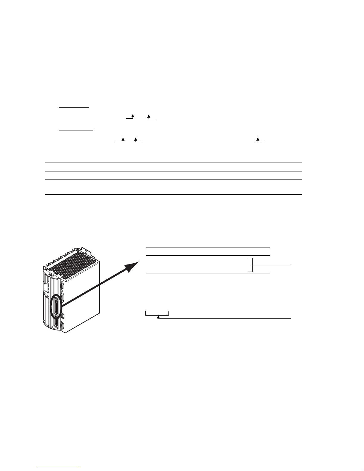
These programmable I/O are represented by binary bit patterns, and it is the bit pattern that you reference when
programming and checking the status of specific inputs and outputs. The bit pattern is referenced 1 to n, from
left to right.
• Onboard I/O
An example response is:
• Expansion I/O
An example response is:
Onboard I/O
I/O Location Programming Status Report, Assignment
Limit Inputs “
Inputs (digital) “DRIVE I/O” connector
Outputs (digital) “DRIVE I/O” connector
. For example, the status command to check all onboard inputs is
*TIN0100_0
Bit 1
.
Bit 5
TIN
.
. For example, the status command to check all digital inputs on I/O brick 2 is
*2TIN0010_0110_1100_0000_XXXX_XXXX_XXXX_XXXX
I/O Brick 2
Bit 1
DRIVE I/O
” connector
LIMFNC, LIMEN, LIMLVL TLIM, LIM
INFNC, INLVL, INEN, ONIN,
INPLC, INSTW
OUT, OUTFNC, OUTLVL,
OUTEN, OUTALL, OUTPLC,
OUTTW, POUT
TIN, IN
TOUT, [OUT]
.
Bit 32
2TIN
.
Limit Inputs
(“DRIVE I/O” connector)
Input bit pattern for
Bit # Pin # Function
1 28 Positive end-of-travel limit
2 29 Negative end-of-travel limit
3 31 Home limit
* The functions listed are the factory default functions; other
functions may be assigned with the
Sample response to
*TLIM110
LIM, TLIM, LIMEN, LIMFNC
*
(limit inputs status) command:
TLIM
LIMFNC
, and
LIMLVL:
command.
8 Gemini GV6K/GT6K Command Reference
www.comoso.com
Page 11
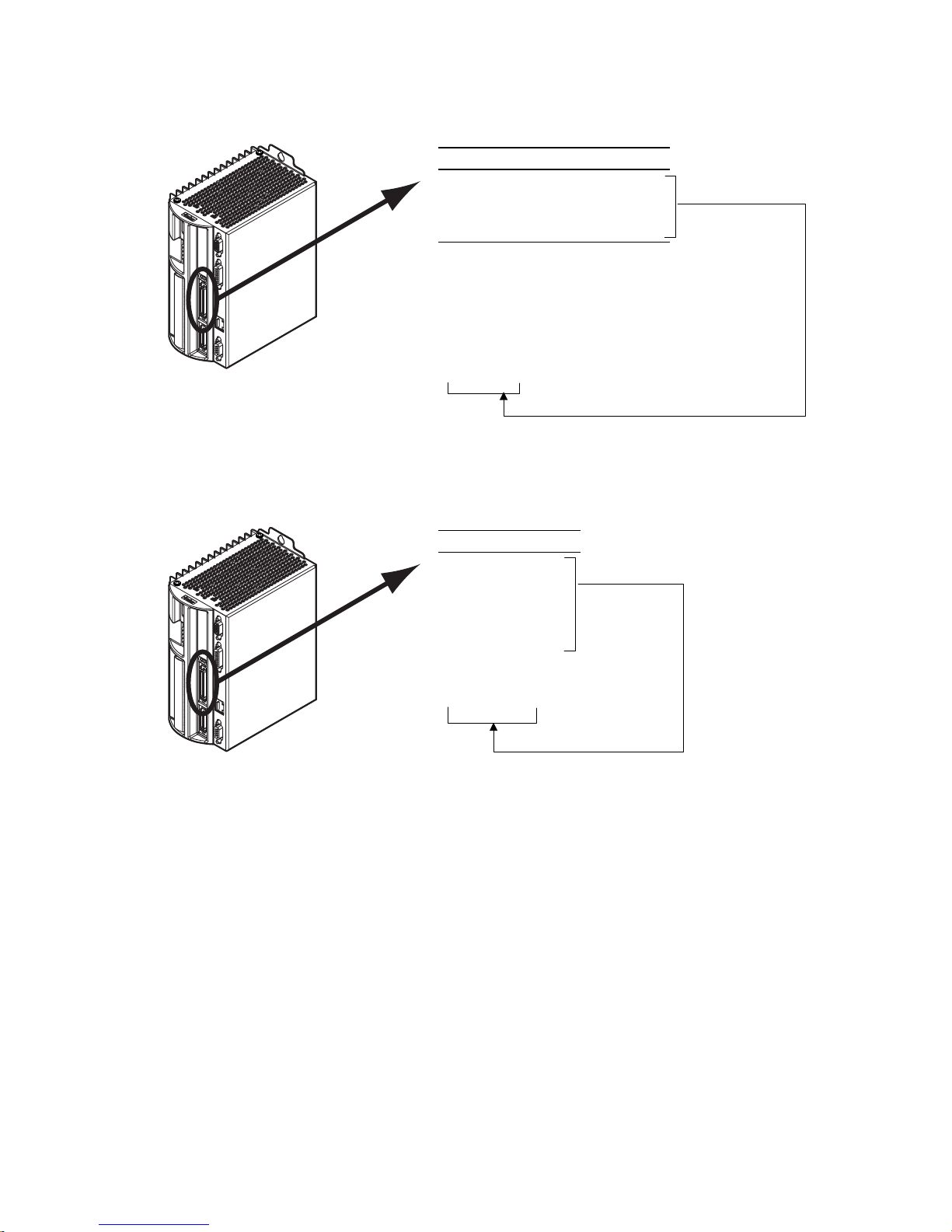
(“DRIVE I/O” connector)
Inputs
Outputs
(“DRIVE I/O” connector)
Input bit pattern for
INEN, INPLC, INSTW
Bit # Pin # Function
1 37 Input 1 (if assigned, TRIG-A)
2 38 Input 2 (if assigned, TRIG-B)
3 39 Input 3
4 34 Input 4
5 35 Input 5 (if assigned, TRIG-M)
* If the input is assigned the “trigger
interrupt” function with the
command:
TRIG-A must be on Input 1
TRIG-B must be on Input 2
TRIG-M must be on input 5
Sample response to
*TIN0010_1
TIN, IN, INFNC, INLVL
, and
ONIN:
*
INFNCi-H
(input status) command:
TIN
,
Output bit pattern for
OUTLVL, OUTEN, OUTALL, OUTPLC, OUTTW, POUT:
Bit # Pin # Function
1 41 Output 1.
2 43 Output 2.
3 45 Output 3.
4 46 Output 4.
5 48 Output 5.
6 49 Output 6.
7 Relay Output 7.
TOUT, [OUT], OUT, OUTFNC
,
Sample response to
(onboard outputs status) command:
*TOUT0000_000
TOUT
Introduction
www.comoso.com
9
Page 12
Expansion I/O Bricks
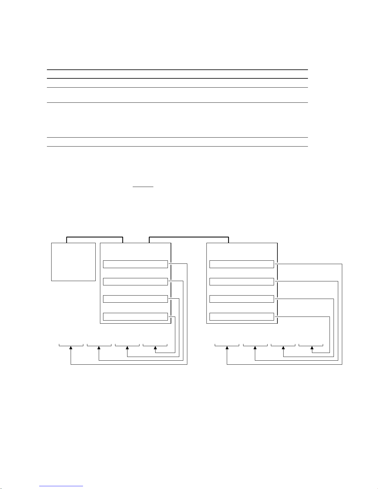
The Gem6K allows you to expand your system I/O by connecting up to eight I/O bricks (see Installation
Guide for connections). Expansion I/O bricks may be ordered separately (referred to as the “EVM32”). Each
I/O brick can hold from 1 to 4 of these I/O SIM modules in any combination:
SIM Type Programming Status Report, Assignment
Digital Inputs SIM (8 inputs)
Digital Outputs SIM (8 outputs)
Analog Inputs SIM (8 inputs)
Analog Outputs SIM (8 outputs)
Each I/O brick has a unique “brick address”, denoted with the “
I/O bricks are connected in series to the “
address #1, the next brick has address #2, and so on. (NOTE: If you leave out the brick address in the
command, the Gem6K will assume you are addressing the command to the onboard I/O.) Each I/O brick
has 32 I/O addresses, referenced as absolute
• SIM slot 1 = I/O points 1-8
• SIM slot 2 = I/O points 9-16
• SIM slot 3 = I/O points 17-24
• SIM slot 4 = I/O points 25-32
INFNC, INLVL, INEN, ONIN, INPLC, INSTW TIN, IN, TIO
OUT, OUTFNC, OUTLVL, OUTEN, OUTALL,
OUTPLC, OUTTW, POUT
• Enable/Disable: ANIEN.
• Voltage range: ANIRNG.
• Joystick setup: JOYAXH, JOYCDB,
JOYCTR, JOYEDB, JOYZ.
• Following master source: ANIMAS, FOLMAS
ANO
” symbol in the command syntax. The
<B>
EXPANSION I/O
” connector on the Gem6K. The 1st I/O brick has
TOUT, [OUT], TIO
• Voltage: TANI, ANI, TIO
TANO, [ANO], TIO
I/O point locations:
Example:
Gem6K
Drive/Controller
Sample response to
*1TIN0000_0010_1100_0000_0100_0001_XXXX_XXXX
command identifies the connected I/O bricks (and installed SIMs), including the status of each I/O point:
TIO
The
*BRICK 1: SIM Type Status Function
1-8: DIGITAL INPUTS 0000_0000 AAAA_AAAA
9-16: DIGITAL INPUTS 0000_0000 AAAA_AAAA
17-24: DIGITAL INPUTS 0000_0000 AAAA_AAAA
25-32: ANALOG INPUTS 0.000,0.000,0.000,0.000,0.000,0.000,0.000,0.000
*BRICK 2: SIM Type Status Function
1-8: DIGITAL OUTPUTS 0000_0000 AAAA_AAAA -- SINKING
9-16: DIGITAL INPUTS 0000_0000 AAAA_AAAA
17-24: NO SIM PRESENT
25-32: DIGITAL OUTPUTS 0000_0000 AAAA_AAAA -- SOURCING
I/O Brick #1
Slot #1 (I/O points 1-8)
Digital Inputs SIM
Slot #2 (I/O points 9-16)
Digital Inputs SIM
Slot #3 (I/O points 17-24)
Digital Inputs SIM
Slot #4 (I/O points 25-32)
Analog Inputs SI M
(digital inputs status) command:
1TIN
I/O Brick #2
Slot #1 (I/O points 1-8)
Digital Outputs SIM
Slot #2 (I/O points 9-16)
Digital Inputs SIM
Slot #3 (I/O points 17-24)
No S IMM insta lled
Slot #4 (I/O points 25-32)
Digital Outputs SIM
Sample response to
*2TOUT0000_0000_XXXX_XXXX_XXXX_XXXX_0000_0000
(digital outputs status) command:
2TOUT
10 Gemini GV6K/GT6K Command Reference
www.comoso.com
Page 13

Programming Error Messages
Depending on the error level setting (set with the
ERRLVL
command), when a programming error is created,
the Gem6K will respond with an error message and/or an error prompt. A list of all possible error messages is
provided in a table below. The default error prompt is a question mark (
ERRBAD
At error level 4 (
the error prompt. At error level 3 (
Error Response Possible Cause
ACCESS DENIED
ALREADY DEFINED FOR THUMBWHEELS
ALTERNATIVE TASK NOT ALLOWED
AXES NOT READY
COMMAND NOT IMPLEMENTED
COMMAND NOT ALLOWED IN PROGRAM
COMMAND/DRIVE MISMATCH
ERROR: MOTION ENDS IN NON-ZERO
VELOCITY
command if you wish.
ERRLVL4
—the factory default setting) the Gem6K responds with both the error message and
ERRLVL3
), the Gem6K responds with only the error prompt.
Program security feature enabled, but the program access input (INFNCi-Q or
LIMFNCi-Q) is not activated.
Attempting to assign an I/O function to an I/O that is already defined as a
thumbwheel I/O.
Attempting to execute a LOCK command directed to another task.
Compiled Profile path compilation error.
Command is not applicable to the Gem6K Series product.
Command is not allowed inside a program definition (between DEF and END).
The command is not appropriate to the type of drive being used (e.g.,
attempting to execute a servo tuning command on a stepper axis)
Compiled Motion: The last GOBUF segment within a PLOOP/PLN loop does not
end at zero velocity, or there is no final GOBUF segment
), but you can change it with the
?
placed outside the loop
.
FOLMAS NOT SPECIFIED
INCORRECT AXIS
INCORRECT BRICK NUMBER
INCORRECT DATA
INPUT(S) NOT DEFINED AS
JOYSTICK INPUT
INSUFFICIENT MEMORY
INVALID COMMAND
No FOLMAS for the axis is currently specified. It will occur if FMCNEW, FSHFC, or
FSHFD commands are executed and no FOLMASØ command was executed, or
FOLMAS0 was executed.
Axis specified is incorrect.
Attempted to execute a command that addresses an I/O brick that is not
connected to your Gem6K controller.
Incorrect command syntax.
Following: Velocity (V), acceleration (A) or deceleration (AD) command is zero
(used by FSHFC & FSHFD).
Attempted to execute JOYCDB, JOYCTR, JOYEDB, or JOYZ before executing
JOYAXH to assign the analog input.
Not enough memory for the user program or compiled profile segments. This
may be remedied by reallocating memory (see MEMORY command description).
Command is invalid because of existing conditions
Introduction
www.comoso.com
11
Page 14

Programming Error Messages
Error Response Possible Cause
INVALID CONDITIONS FOR COMMAND
INVALID CONDITIONS FOR
S_CURVE ACCELERATION—FIELD n
INVALID DATA
(continued)
System not ready for command (e.g., LN command issued before the L
command).
Following (these conditions can cause an error during Following):
• The FOLMD value is too small to achieve the preset distance and still
• A phase shift cannot be performed:
• The FOLEN1 command was given while a profile was suspended by a
Average (AA) acceleration or deceleration command (e.g., AA, ADA, HOMAA,
HOMADA, etc.) with a range that violates the equation ½A ≤ AA ≤ A (A is the
max. accel or decel command—e.g., A, AD, HOMA, HOMAD, etc.)
Data for a command is out of range.
Following (these conditions can cause an error during Following):
• The parameter supplied with the command is valid.
• Error if a GO command is given in the preset positioning mode (MCØ) and:
remain within the FOLRN/FOLRD ratio.
FSHFD.... Error if already shifting or performing other time based move.
FSHFC.... Error if currently executing a FSHFD move, or if currently
GOWHEN.
FFILT Error if: smooth number is not 0-4
FMCLEN.. Error if: master steps > 999999999 or negative
FMCP ......Error if: master steps > 999999999 or < -999999999
FOLMD.... Error if: master steps > 999999999 or negative
FOLRD.... Error if: master steps > 999999999 or negative
FOLRN.... Error if: follower steps > 999999999 or neg ative
FSHFC.... Error if: number is not 0-3
FSHFD.... Error if: follower steps > 999999999 or < -999999999
GOWHEN.. Error if: position > 999999999 or < -999999999
WAIT ......Error if: position > 999999999 or < -999999999
FOLRN = zero
FOLMD = zero, or too small
(see Following chapter in the Programmer’s Guide)
executing another FSHFC move in the opposite direction.
INVALID FOLMAS SPECIFIED
INVALID RATIO
INVALID TASK IDENTIFIER
LABEL ALREADY DEFINED
MASTER SLAVE DISTANCE MISMATCH
MAXIMUM COMMAND LENGTH EXCEEDED
MAXIMUM COUNTS PER SECOND
EXCEEDED
MOTION IN PROGRESS
NEST LEVEL TOO DEEP
Following: An illegal master was specified in FOLMAS. A follower may never
use its own commanded position or feedback source as its master.
Following: Error if the FOLRN:FOLRD ratio after scaling is > 127 when a GO is
executed.
Attempting to launch a PEXE or EXE command into the supervisor task (task 0).
Defining a program or label with an existing program name or label name.
Attempting a preset Following move with a FOLMD value that is too small.
Command exceeds the maximum number of characters.
Velocity value is greater than 1,600,000 counts/sec.
Attempting to execute a command not allowed during motion (see Restricted
Commands During Motion section in the Programmer's Guide.)
Following: The FOLEN1 command was given while that follower was moving in
a non-Following mode.
IFs, REPEATs, WHILEs, or GOSUBs nested greater than 16 levels
12 Gemini GV6K/GT6K Command Reference
(for each type).
www.comoso.com
Page 15

Programming Error Messages
Error Response Possible Cause
NO MOTION IN PROGRESS
NO PATH SEGMENTS DEFINED
NO PROGRAM BEING DEFINED
NOT ALLOWED IN PATH
NOT VALID DURING FOLLOWING
MOTION
NOT VALID DURING RAMP
OUTPUT USED AS OUTFNC
PROFILE ALREADY MOVING
PROFILE NOT COMPILED
(continued)
Attempting to execute a command that requires motion, but motion is not in
progress.
Compiled Profile compilation error.
END command issued before a DEF command.
Compiled Profile path compilation error.
A GO command was given while moving in the Following mode (FOLEN1) and
while in the preset positioning mode (MCØ).
A GO command was given while moving in a Following ramp and while in the
continuous positioning mode (MC1). Following status (FS) bit #3 will be set to 1.
A FOLEN command was given during one of these conditions:
• During a shift (FSHFC or FSHFD)
• During a change in ratio (FOLRN/FOLRD)
• During deceleration to a stop
Attempting to change an output that is not an OUTFNCi-A output.
Compiled Profile compilation error.
Attempting to execute a profile that has not been compiled.
STRING ALREADY DEFINED
STRING IS A COMMAND
UNDEFINED LABEL
WARNING: POINTER HAS WRAPPED
AROUND TO DATA POINT 1
WARNING: ENABLE INPUT INACTIVE
WARNING: DEFINED WITH ANOTHER
TW/PLC
A string (program name or label) with the specified name already exists.
Defining a program or label that is a command or a variant of a command.
Command issued to product is not a command or program name.
During the process of writing data (DATTCH) or recalling data (DAT), the pointer
reached the last data element in the program and automatically wrapped
around to the first datum in the program.
ENABLE
Duplicate I/O in multiple thumbwheel definitions.
input is no longer connected to ground (
GND
).
Introduction
www.comoso.com
13
Page 16

Identifying Bad Commands
To facilitate program debugging, the Transfer Command Error (
TCMDER
) command allows you to transfer
the first command that the controller detects as an error. This is especially useful if you receive an error
message when running or downloading a program, because it catches and remembers the command that
caused the error.
Using Motion Planner
will detect the bad command and respond with an error message, followed by the
prompt (
automatically (see example below).
). If the bad command was detected on download, the bad command is reported
?
NOTE: If you are not using Motion Planner, you'll have to type in the TCMDER
: If you are typing the command in a live terminal emulator session, the controller
ERRBAD
error
command at the error
prompt to display the bad command.
Once a command error has occurred, the command and its fields are stored and system status bit #11
(reported in the
TSSF, TSS
and SS commands) is set to 1. The status bit remains set until the
TCMDER
command is issued.
Example Error Scenario:
1. In Motion Planner's program editor, create and save a program with a programming error:
DEL badprg ; Delete a program before defining and downloading
DEF badprg ; Begin definition of program called badprg
MA1 ; Select the absolute preset positioning mode
A25 ; Set acceleration
AD11 ; Set deceleration
V5 ; Set velocity
VAR1=0 ; Set variable #1 equal to zero
GO1 ; Initiate move
IF(VAR1<)16 ; MISTYPED IF STATEMENT - should be typed as "IF(VAR1<16)"
VAR1=VAR1+1 ; If variable #1 is less than 16, increment the counter by 1
NIF ; End IF statement
END ; End programming of program called badprg
2. Using Motion Planner's terminal emulator, download the program to the Gem6K Series product. Notice
that an error response identifies the bad command as an “
> *NO ERRORS
*INCORRECT DATA
> *IF(VAR1<)16
INCORRECT DATA
” item and displays it:
14 Gemini GV6K/GT6K Command Reference
www.comoso.com
Page 17
S-Curve Acceleration/Deceleration Profiling
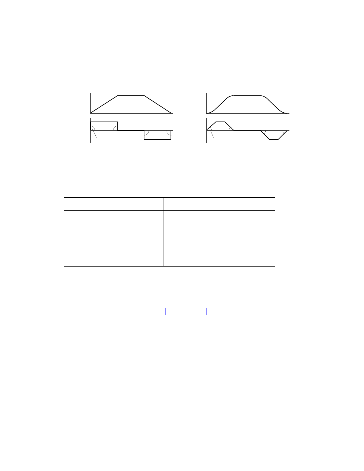
The Gem6K allows you to perform S-curve move profiles, in addition to the usual trapezoidal profiles.
S-curve profiling provides smoother motion control by reducing the jerk (rate of change) in acceleration
and deceleration portions of the move profile (see drawing below). Because S-curve profiling reduces jerk,
it improves position tracking performance, especially in linear interpolation applications.
Accel
Maximum Jerk
Decel Velocity
Trapezoidal
Time
Time
Velocity
Decel Accel
Less Jerk
S-Curve
Time
Time
S-Curve Programming Requirements
To program an S-curve profile, you must use the average accel/decel commands provided in the Gem6K
programming language. For every maximum accel/decel command (e.g., A, AD,
JOGAD
, etc.) there is an average command for S-curve profiling (see table below).
Maximum Accel/Decel Commands:
Command Function
A
AD
HOMA
HOMAD
JOGA
JOGAD
JOYA
JOYAD
LHAD
LSAD
Acceleration
Deceleration
Home Acceleration
Home Deceleration
Jog Acceleration
Jog Deceleration
Joystick Acceleration
Joystick Deceleration
Hard Limit Deceleration
Soft Limit Deceleration
Average (“S-Curve”) Accel/Decel Commands:
Command Function
AA
ADA
HOMAA
HOMADA
JOGAA
JOGADA
JOYAA
JOYADA
LHADA
LSADA
Average Acceleration
Average Deceleration
Average Home Acceleration
Average Home Deceleration
Average Jog Acceleration
Average Jog Deceleration
Average Joystick Acceleration
Average Joystick Deceleration
Average Hard Limit Deceleration
Average Soft Limit Deceleration
HOMA, HOMAD, JOGA
,
Determining the S-Curve Characteristics
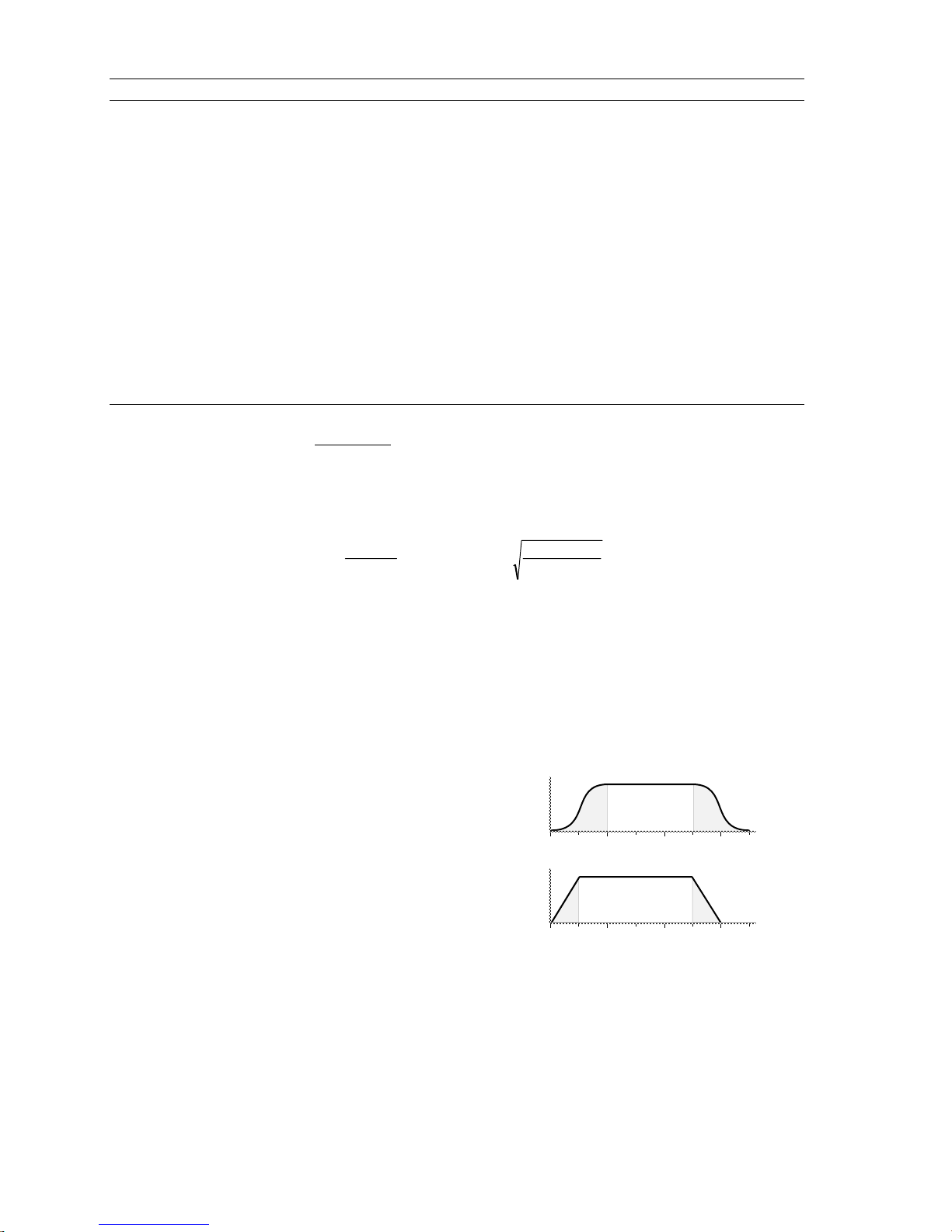
The command values for average accel/decel (AA,
the characteristics of the S-curve. To smooth the accel/decel ramps, you must enter average accel/decel
command values that satisfy the equation ½
AA represents average accel/decel. Given this requirement, the following conditions are possible:
Introduction
A ≤ AA < A , where A represents maximum accel/decel and
, etc.) and maximum accel/decel (A, AD, etc.) determine
ADA
15
www.comoso.com
Page 18
Acceleration Setting Profiling Condition
AA > ½ A, but AA < A S-curve profile with a variable period of constant acceleration. Increasing the AA value above
AA = ½ A Pure S-curve (no period of constant acceleration—smoothest motion).
AA = A Trapezoidal profile (but can be changed to an S-curve by specifying a new AA value less than A).
AA < ½ A; or AA > A When you issue the GO command, the move will not be executed and an error message,
AA = zero S-curve profiling is disabled. Trapezoidal profiling is enabled. AA tracks A. (Track means the
AA ≠ zero and AA ≠ A S-curve profiling is enabled
AA > ½ A Average accel/decel is raised above the pure S-curve level; this decreases the time required to
No AA value ever entered Profile will default to trapezoidal. AA tracks A.
If you never change the A or
However, once you change
For example, if you never change the
once you change
AD
the pure S-curve level (AA > ½ A), the time required to reach the target velocity and the target
distance is decreased. However, increasing AA also increases jerk.
*INVALID CONDITIONS FOR S_CURVE ACCELERATION—FIELD n, will be displayed.
command’s value will match the other command’s value and will continue to match whatever
the other command's value is set to.) However, if you enter an average decel command (e.g.,
ADA, HOMADA, etc.) equal to zero, you will receive the “INVALID DATA-FIELD n” error.
axis must comply with this equation: ½ A ≤ AA < A.
reach the target velocity and distance. However, increasing AA also increases jerk. After
increasing AA, you can reduce jerk by increasing A, but be aware that increasing A requires a
greater torque to achieve the commanded velocity at the mid-point of the acceleration profile.
deceleration commands,
AA
only for standard moves.
deceleration will track
AA
All subsequent standard moves for that
acceleration.
AA
A deceleration, AA deceleration will no longer track changes in AA acceleration.
or
, the
AD
command value will no longer track the changes in the
ADA
command values,
ADA
will track the
ADA
command value. But
AA
command value.
AA
Calculating Move Times. The calculation for determining S-curve average accel and decel move times is
as follows (calculation method identical for S-curve and trapezoidal moves):
Time =
Velocity
A
avg
or Time =
2 Distance
∗
A
avg
Scaling affects the
acceleration (
A, AD
AA average acceleration (
AA, ADA
, etc.). See page 19 for details on scaling.
, etc.) the same as it does for the A maximum
NOTE: Equations for calculating jerk are provided on page 17.
Programming Example (see move profile drawings below)
; In this example, prog1 executes a pure S-curve and takes 1 second
; to reach a velocity of 5 rps; prog2 executes a trapezoidal profile
; and takes 0.5 seconds to reach a velocity of 5 rps.
SCALE0 ; Disable scaling
DEL Prog1 ; Delete program called prog1
DEF Prog1 ; Begin definition of prog1
MA0 ; Select incremental positioning mode
D40000 ; Set distance to 40,000
A10 ; Set max. accel to 10 revs/sec/sec
AA5 ; Set avg. accel to 5 revs/sec/sec
AD10 ; Set max. decel to 10 revs/sec/sec
ADA5 ; Set avg. decel to 5 revs/sec/sec
V5 ; Set velocity to 5 revs/sec
GO1 ; Execute motion
END ; End definition of prog1
DEL Prog2 ; Delete program called prog2
DEF Prog2 ; Begin definition of prog2
MA0 ; Select incremental positioning mode
D40000 ; Set distance to 40,000
A10 ; Set max. accel to 10 revs/sec/sec
AA10 ; Set avg. accel to 10 revs/sec/sec
AD10 ; Set max. decel to 10 revs/sec/sec
ADA10 ; Set avg. decel to 10 rev/sec/sec
V5 ; Set velocity to 5 revs/sec
GO1 ; Execute motion
END ; End definition
of program #2
V
0
V
0
Move profiles
123
123
S-Curve
T
Trapezoidal
T
16 Gemini GV6K/GT6K Command Reference
www.comoso.com
Page 19
2
2
2
A
2
3
2
3
2
2
2
3
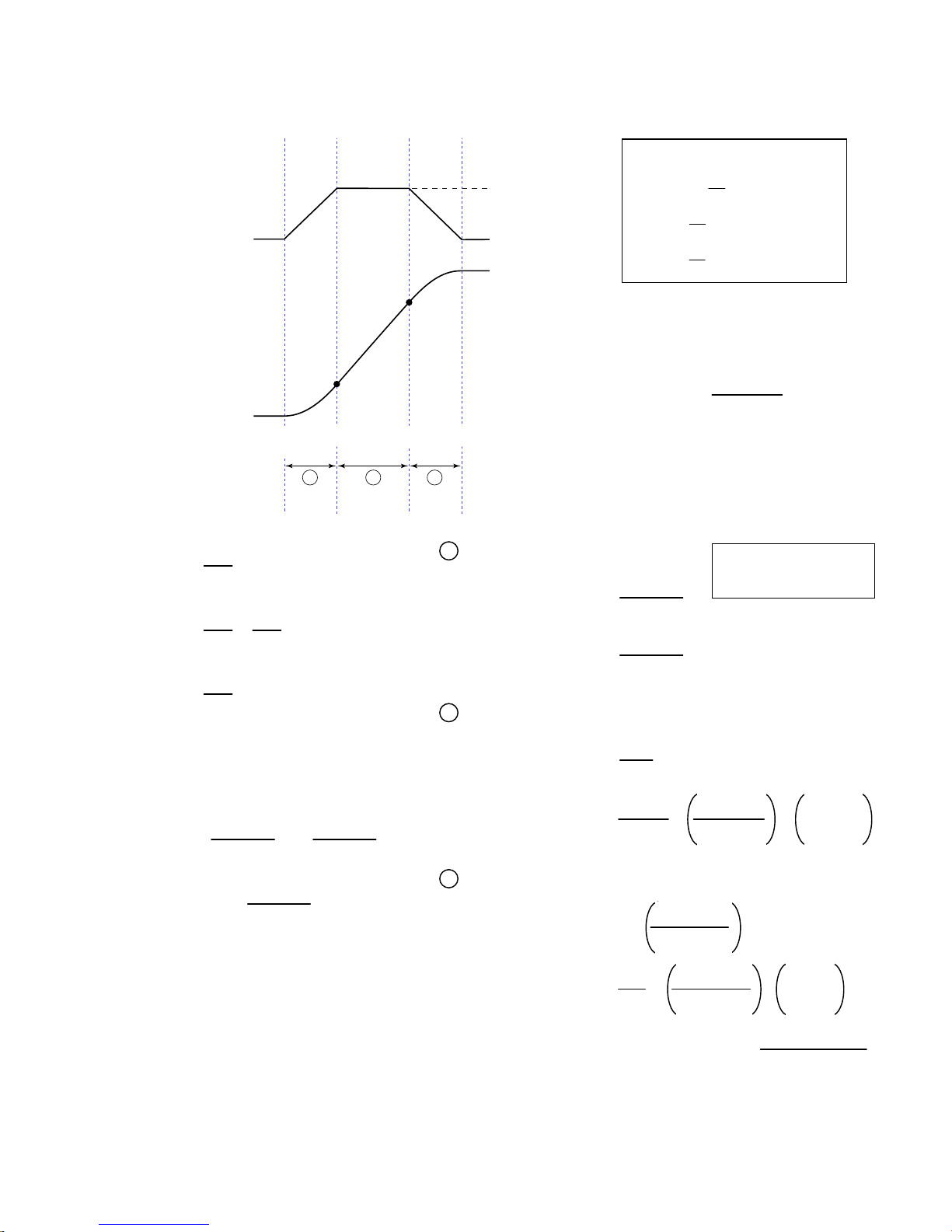
Calculating Jerk
Rules of Motion:
A
(Programmed Accel)
a
Zero Acceleration
V
(Programmed Velocity)
V
2
Assuming the accel profile starts
when the load is at zero velocity and
the ramp to the programmed velocity
is not compromised:
Zero Velocity
V
1
Ø
(zero)
t
1
A B C
t
2
t
3
Jerk
A = programmed acceleration
AA = average acceleration
V = programmed velocity
t1 =
A
J
A
t1 ≥ t ≥ Ø
a (t) = JA * t
J
* t
A
v (t) =
V
=
t
2
AA
V
=
t
3
AA
NOTE: t
A
J
- t2 = t1
3
A
B
t2 ≥ t > t1
d (t) =
a (t) = A
2
J
* t
A
6
A
v (t) = + A * (t - t1)
2J
V1 =
V2 = V -
J
* t
A
1
A
d (t) = + + V1 * (t - t1)
=
2
A
2 * J
2 * J
A
C
t3 ≥ t > t2
A
a (t) = A - (JA * (t - t2))
v (t) = V -
A
* t
J
A
6
V
d (t) = + - V * (t3 - t)
2AA
Starting at a Non-Zero Velocity
initial velocity, the move comprises two components: a constant velocity component, and
an s-curve component. Typically, the change of velocity should be used in the S-curve
calculations. Thus, in the calculations above, you would substitute “(VF - VO)” for “V”
(VF = final velocity, VO = initial velocity). This is shown in the jerk equation (right).
: If starting the acceleration profile with a non-zero
da
=
Jerk
dt
dv
=
dt
dx
= (x = distance)
v
dt
A2 * AA
=
= J
A
V (A-AA)
(A, AD, HOMAD, etc.)
(AA, ADA, HOMAA, etc.)
(V, HOMV, etc.)
a (t) = acceleration at time t
(t) = velocity at time t
v
(t) = distance at time t
d
1
A * (t - t
)
1
2
* (t3 - t)
J
A
2
JA (t3 - t)
6
= J
Jerk
=
A
A2 * AA
- VO) (A-AA)
(V
F
Introduction
www.comoso.com
17
Page 20
Units of Measure and Scaling
Units of Measure without Scaling
Scaling is disabled (
• Stepper axes: All distance values entered are in commanded counts (sometimes referred to as motor
steps), and all acceleration, deceleration and velocity values entered are internally multiplied by the
DRES
command value.
• Servo axes:
Accel/Decel Revs/sec/sec *
Velocity Revs/sec *
Distance Counts **
SCALEØ
Motion Attribute Encoder or Resolver
* All accel/decel & velocity values are internally multiplied by the ERES command value.
** Distance is measured in the counts received from the feedback device.
) as the factory default condition:
Units of Measure
What is Scaling?
Scaling allows you to program acceleration, deceleration, velocity, and position values in units of measure
that are appropriate for your application. The
SCALE1
(
to enable,
SCALEØ
to disable). The motion type(s) you are using in your application determines
which scale factor commands you need to configure:
Type of Motion Accel/Decel Scaling Velocity Scaling Distance Scaling
Standard Point-to-Point Motion
Following
SCLA SCLV SCLD
SCLA SCLV
SCALE
command is used to enable or disable scaling
SCLD for follower distances
SCLMAS for master distances
When Should I Define Scaling Factors?
Scaling calculations are performed when a program is defined or downloaded. Consequently, you must
enable scaling (
DEF
(
), uploading (
SCLD, SCLV
RECOMMENDED
SCALE1
and
) and define the scaling factors (
TPROG
SCLMAS
), or running (
) are automatically saved in the Gem6K’s battery-backed RAM.
RUN
) the program. NOTE: All scaling settings (
: Place the scaling commands at the beginning of your program file, before the location
of any defined programs. This ensures that the motion parameters in subsequent programs in your program
file are scaled correctly. When you use Motion Planner’s scaling setup wizard, the scaling commands are
automatically placed in the appropriate location in your program file.
ALTERNATIVE
: Scaling factors could be defined via a terminal emulator just before defining or
downloading a program. Because scaling command values are saved in battery-backed RAM (remembered
after you issue a
command or cycle power to the Gem6K), all subsequent program definitions and
RESET
downloads will be scaled correctly.
• Scaling commands are not allowed in a program. If there are scaling commands in a program, the Gem6K
will report an error message (“COMMAND NOT ALLOWED IN PROGRAM”) when the program is downloaded.
• If you intend to upload a program with scaled motion parameters, be sure to use Motion Planner. Motion
Planner automatically uploads the scaling parameters and places them at the beginning of the program file
containing the uploaded program from the Gem6K. This ensures correct scaling when the program file is later
downloaded.
SCLD, SCLA, SCLV, SCLMAS
NOTES
) prior to defining
SCALE, SCLA
,
18 Gemini GV6K/GT6K Command Reference
www.comoso.com
Page 21

Acceleration & Deceleration Scaling (SCLA)
Stepper Axes: If scaling is enabled (
SCALE1
), all accel/decel values entered are internally multiplied by
the acceleration scaling factor to convert user units/sec/sec to commanded counts/sec/sec.
The scaled values are always in reference in commanded counts, regardless of the existence
of an encoder.
Servo Axes: If scaling is enabled (
SCALE1
), all accel/decel values entered are internally multiplied by
the acceleration scaling factor to convert user units/sec/sec to encoder or resolver
counts/sec/sec.
All accel/decel commands (e.g., A, AA, AD,
HOMA, HOMAD, JOGA
, etc.) are multiplied by the
SCLA
command value.
As the accel/decel scaling factor (
changes, the resolution of the accel and decel
values and the number of positions to the right of
the decimal point also change (see table at right).
An accel/decel value with greater resolution than
allowed will be truncated (e.g., if scaling is set to
SCLA1Ø
, the
truncated to
A9.9999
A9.9
command would be
).
SCLA
)
SCLA value
1 - 9 ............................................ 0
10 - 99 ........................................ 1
100 - 999 .................................... 2
1000 - 9999 ................................ 3
10000 - 99999 ............................ 4
100000 - 999999........................5
(counts/unit/unit) Decimal Places
The following equations can help you determine the range of acceleration and deceleration values.
Axis Type Min. Accel or Decel (resolution) Max. Accel or Decel
Stepper
Servo
0.001 ∗DRES
SCLA
Encoder Feedback:
0.001 ∗ ERES
SCLA
999.9999 ∗DRES
SCLA
Encoder Feedback:
999.9999 ∗ ERES
SCLA
Velocity Scaling (SCLV)
Stepper Axes: If scaling is enabled (
velocity scaling factor to convert user units/sec to commanded counts/sec. The scaled
values are always in reference to commanded counts (sometimes referred to as “motor
steps”).
Servo Axes: If scaling is enabled (
velocity scaling factor to convert user units/sec to encoder or resolver counts/sec.
All velocity commands (e.g., V,
command value.
As the velocity scaling factor (
change (see table below). A velocity value with greater resolution than allowed will be truncated. For
example, if scaling is set to
SCLV Value
(counts/unit)
1 - 9
10 - 99
100 - 999
1000 - 9999
10000 - 99999
100000 - 999999
SCLV10
SCALE1
SCALE1
HOMV, HOMVF, JOGVH, JOGVL
SCLV
) changes, the velocity command's range and its decimal places also
, the
), all velocity values entered are internally multiplied by the
), all velocity values entered are internally multiplied by the
, etc.) are multiplied by the
V9.9999
Velocity Resolution
(units/sec)
1
0.1
0.01
0.001
0.0001
0.00001
command would be truncated to
Decimal Places
0
1
2
3
4
5
V9.9
SCLV
.
Introduction
www.comoso.com
19
Page 22

Use the following table to determine the maximum velocity for your product type.
Max. Velocity for Stepper Axes Max. Velocity for Servo Axes
50 revs/sec 200 revs/sec
: These velocity limitations are hardware based. Make sure the velocity scaling value used with the desired velocity
NOTE
(V command) does not exceed these velocities. The Gem6K will generate an error message if you try to exceed these
maximums. The maximum servo velocity may also be limited when using encoder feedback, depending on the encoder
resolution `used. Refer to the Gem6K Hardware Installation Guide for the maximum encoder input frequency.
Distance Scaling (SCLD and SCLMAS)
Stepper Axes: If scaling is enabled (
SCALE1
), all distance values entered are internally multiplied by the
distance scaling factor to convert user units to commanded counts (“motor steps”).
Servo Axes: If scaling is enabled (
SCALE1
), all distance values entered are internally multiplied by the
distance scaling factor to convert user units to encoder or analog input counts.
All standard motion distance commands (e.g.,
command value. The only exception is for master distance values (see table below):
SCLD
Scaling for Following Motion:
SCLMAS command defines the master’s distance scale factor. The Following-related commands that are affected
by SCLD and SCLMAS are listed in the table below.
Commands Affected by Master Scaling (
FMCLEN: Master Cycle Length
FMCP: Master Cycle Position Offset
FOLMD: Master Distance
FOLRD: Follower-to-Master Ratio (Denominator)
GOWHEN: Conditional GO (left-hand variable is PMAS)
TPMAS & [
TVMAS & [
SCLD
As the
]: Position of Master Axis
PMAS
]: Velocity of Master Axis
VMAS
SCLMAS
or
scaling factor changes, the distance command’s range and its decimal places also
The SCLD command defines the follower axis distance scale factor, and the
D, PSET, REG, SMPER, STRGTD
SCLMAS
Commands Affected by Follower Scaling (
)
FOLRN: Follower-to-Master Ratio (Numerator)
FGADV: Geared Advance
FSHFD: Preset Phase Shift
GOWHEN: Conditional GO (left-hand variable ≠ PMAS)
TPSHF & [
TPSLV & [
PSHF
PSLV
) and are multiplied by the
SCLD
]: Net Position Shift of Follower
]: Position of Follower Axis
change (see table below). A distance value with greater resolution than allowed will be truncated. For
example, if scaling is set to
SCLD4000
D105.2776
, the
command would be truncated to
D105.277
)
.
SCLD or SCLMAS
(counts/unit)
1 - 9 1.0 0 - ±999999999 0
10 - 99 0.10 0.0 - ±99999999.9 1
100 - 999 0.010 0.00 - ±9999999.99 2
1000 - 9999 0.0010 0.000 - ±999999.999 3
10000 - 99999 0.00010 0.0000 - ±99999.9999 4
100000 - 999999
NOTE FRACTIONAL STEP TRUNCATION NOTE
Value
If you are operating in the incremental mode (MAØ), or specifying master distance values with
FOLMD, when the distance scaling factor (SCLD or SCLMAS) and the distance value are multiplied,
a fraction of one step may be left over. This fraction is truncated when the distance value is used
in the move algorithm. This truncation error can accumulate over a period of time, when
performing incremental moves continuously in the same direction. To eliminate this truncation
problem, set SCLD or SCLMAS to 1, or a multiple of 10.
20 Gemini GV6K/GT6K Command Reference
Distance Resolution
(units)
0.00001 0.00000 - ±9999.99999 5
Distance Range *
(units)
www.comoso.com
Decimal
Places
Page 23

Scaling Example — Steppers (GT6K)
We configure for a 25,000 step/rev system attached to 5-pitch leadscrew. The user wants to program
motion parameters in inches; therefore the scale factor calculation is: 25,000 steps/rev x 5 revs/inch =
125,000 steps/inch. For instance, with a scale factor of 125,000, the operator could enter a move distance
value of 2.000 and the controller would send out 250,000 pulses, corresponding to two inches of travel.
SCALE1 ; Enable scaling
DRES25000 ; Set drive resolution to 25,000 steps/rev
SCLD125000 ; Allow user to enter distance in inches
SCLV125000 ; Allow user to enter velocity in inches/sec
SCLA125000 ; Allow entering accel/decel in inches/sec/sec
DRESET ; Reset the drive so the DRES value is accepted
Scaling Example — Servos (GV6K)
We configure for a 4,000 count/rev servo motor/drive system (using a 1000-line encoder) attached to a 5pitch leadscrew. The user wants to position in inches; therefore, the scale factor calculation is 4,000
counts/rev x 5 revs/inch = 20,000 counts/inch.
SFB1 ; Select encoder feedback
ERES4000 ; Set encoder resolution to 4000 steps/rev (post quadrature)
SCALE1 ; Enable scaling
SCLD20000 ; Allow user to enter distance values in inches
SCLV20000 ; Allow user to enter velocity values in inches/sec
SCLA20000 ; Allow user to enter accel/decel values in inches/sec/sec
DRESET ; Reset the drive so the DRES value is accepted
Scaling Example — Following
Typically, the master and follower scale factors are programmed so that master and follower units are the
same, but this is not required. Consider the scenario below as an example.
The master is a 1000-line encoder (4000 counts/rev post-quadrature) mounted to a 50 teeth/rev pulley
attached to a 10 teeth/inch conveyor belt, resulting in 80 counts/tooth (4000 counts/50 teeth = 80
counts/tooth). To program in inches, you would set up the master scaling factor with the
command (80 counts/tooth ∗ 10 teeth/inch = 800 counts/inch).
The follower is a servo motor with position feedback from a 1000-line encoder (4000 counts/rev). The
motor is mounted to a 4-pitch (4 revs/inch) leadscrew. Thus, to program in inches, you would set up the
follower scaling factor with the
SCLD16000
command (4000 counts/rev ∗ 4 revs/inch = 16000
counts/inch).
SCALE1 ; Enable scaling
SCLMAS800 ; Master scaling (80 counts/tooth * 10 teeth/inch = 800 counts/inch)
SCLD16000 ; Follower scaling (4000 counts/rev * 4 revs/inch = 16000 counts/inch)
SCLMAS800
Introduction
www.comoso.com
21
Page 24

www.comoso.com
Page 25
Special Programming
Characters
%
Type Multi-Tasking
Syntax <a_>i%<command>
Units i = task number
Range 1-10
Default 1
Response n/a
See Also
LOCK, [SWAP], [TASK], TSKAX, TSKTRN, TSWAP, TTASK
Task Identifier
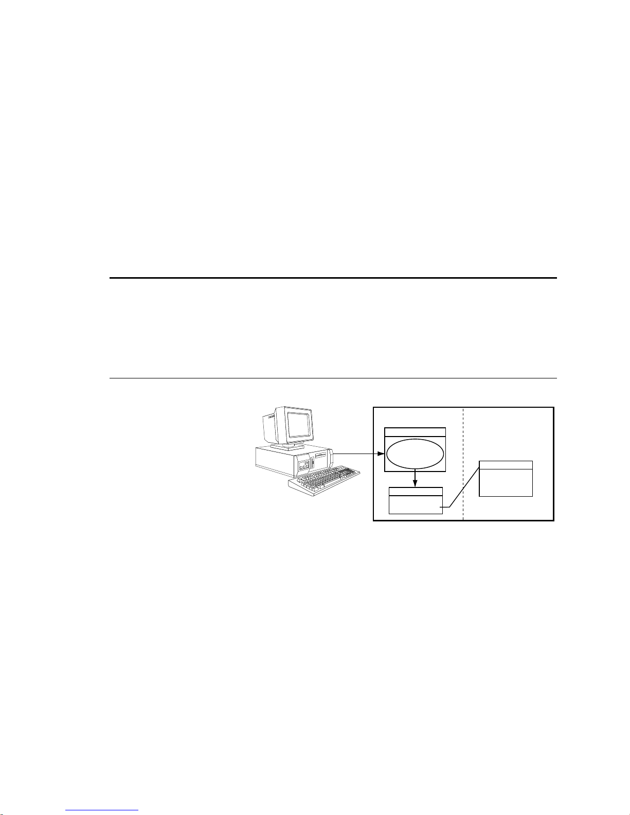
Use the Task Identifier (%)
prefix to specify that the
associated command will affect
the indicated task number. For
most simple multi-tasking
applications, the
prefix is
%
used to start a program running
in a specific task. For example,
the drawing on the right
illustrates how the
1%move1
command starts the program
called “
(specified with the
move1
” in task 1
prefix).
1%
1%move1
Gx6K Drive
Supervisor
Assign Task 1 to
execute the
"move1" program
Task 1
Execute the
"move1" program.
Product Rev
GT6K 6.0
GV6K 6.0
Program MemoryTask Management
Program: move1
DEF move1
---
---
--END
Command Descriptions 23
www.comoso.com
Page 26
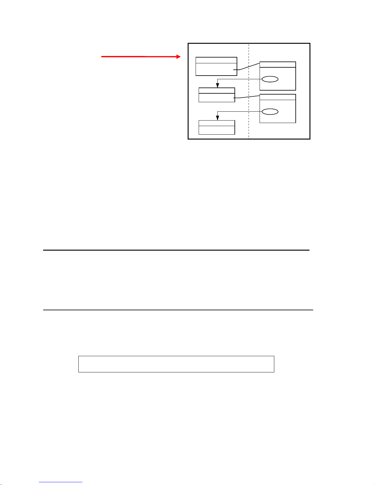
Because the
associated command will affect, new tasks can be
started from within other tasks, as shown in the
drawing on the right.
Within a program in a task, it is not necessary to use
the % prefix unless trying to initiate a program or
command in a different task. For example, if the
program running in task 3 executes a
fill
command, only task 3 is placed into
If the
fill
command, task 3 executes the command, but the
2%PS
program being executed in task 2 is paused, not task 3.
prefix specifies the task number that the
%
COMEXC1
COMEXC1
mode.
program running in task 3 also executes a
Gx6K Drive
Program MemoryTask Management
Supervisor
Running "main"
Task 1
Execute "move1"
Task 3
Execute "fill"
Program: main
DEF main
---
--1%move1
---
--END
Program: move1
DEF move1
---
--3%fill
---
--END
How the Task Supervisor Works: The “Task Supervisor” (also referred to as Task Ø
execution environment. It contains the command buffer and parser. Immediate commands and commands
executed from the communications buffer are implicitly directed to affect the supervisor unless exp licitly
directed to a task with the
prefix. Only the supervisor executes buffered commands from the
%
communications buffer. If the supervisor is executing a program, incoming commands will be buffered,
not executed. If the supervisor is not executing a program, it will execute commands from the input
command buffer, even if the other tasks are executing programs. If a command in the command buffer has
a task prefix, it is still executed by the supervisor, but affects the task specified by the prefix.
) is the main program
[ ! ]
Type Operator (Other)
Syntax <a_>!<command>
Units n/a
Range n/a
Default n/a
Response n/a
See Also COMEXC
mmediate Command Identifier
Product Rev
GT6K 6.0
GV6K 6.0
The Immediate Command Identifier (!) changes a buffered command into an immediate command. All
immediate commands are processed immediately, even before previously entered buffered commands.
All Gem6K commands are buffered.
The commands that use the
identifier are identified in the
!
portion of the command description.
Syntax
NOTE
A command with the ! prefix cannot be stored in a program.
24 Gemini GV6K/ GT6K Command Reference
www.comoso.com
Page 27

[ @ ]
Type Operator (Other)
Syntax @<command><field1>
Units n/a
Range n/a
Default n/a
Response n/a
See Also ANIEN, ANIRNG, INEN, INLVL, OUT, OUTALL, OUTEN, OUTLVL, TANI,
TANO, TIN, TIO, TOUT
Global Command Identifier
Product Rev
GT6K 6.0
GV6K 6.0
The Global Command Identifier (@) is used to set the value of all fields to the value entered only in the first
field. For example,
commands can use the
;
Type Operator (Other)
Syntax ;<this is a comment>
Units n/a
Range n/a
Default n/a
Response n/a
See Also None
@OUT1 sets output #1 on for all I/O bricks. If you have any doubts about which
symbol, refer to the
@
Begin Comment
portion of the command description.
Syntax
Product Rev
GT6K 6.0
GV6K 6.0
The Begin Comment (;) command is used to comment application programs. The comment begins with a
semicolon (
) and is terminated by a command delimiter. The comment is not stored in a program. An
;
example of using the comment delimiter is as follows:
DEF pick ; Begin definition of program pick<cr>
$
Type Operator (Other)
Syntax <a_><!>$<t>
Units t = text name
Range Text name of 6 characters or less
Default n/a
Response n/a
See Also DEF, DEL, END, GOSUB, GOTO, JUMP, RUN, TLABEL
Label Declaration
Product Rev
GT6K 6.0
GV6K 6.0
The Label Declaration ($) command defines the current location as the label specified. A label consists of 6
or fewer alpha-numeric characters and must start with an alpha-character, not a number. Labels can only be
defined within a program or subroutine. The
label. The
deleted by a
command can also be used to start executing statements at a label. The label cannot be
RUN
command. However, when the program that contains the label is deleted, all labels
DEL
GOTO, GOSUB
or
commands can be used to branch to a
JUMP
contained within the program will be deleted.
NOTE: The maximum number of labels possible is 600.
A label declaration cannot consist of any of the following characters:
!, _, #, $, %, ^, &, *, (, ), +, -, {, }, \, |, ", :, ;, ', <, >, ,, ., ?, /, =
A label cannot have the same name as a Gem6K command. For example, $A and
NOTE:
are illegal
$A123
labels.
Command Descriptions 25
www.comoso.com
Page 28

Example
DEF pick ; Begin definition of program called pick
GO1 ; Initiate motion
IF(VAR1=5) ; If variable 1 = 5 then do commands between IF and ELSE,
; otherwise commands between ELSE and NIF
GOTO pick1 ; Goto label pick1
ELSE ; Else part of IF command
GOTO pick2 ; Goto label pick2
NIF ; End IF command
$pick1 ; Label declaration for pick1
TAS ; Report axis status
BREAK ; Break out of current subroutine or program
$pick2 ; Label declaration for pick2
TPC ; Report commanded position
END ; End program definition
RUN pick ; Execute program named pick
[ # ]
Type Operator (Other)
Syntax <a_>!#<i>
Units i = number of commands to execute from the buffer
Range i = 1 - 200
Default 1
Response n/a
See Also DEF, HELP, STEP, TRACE, TRANS
Step Through a Program
Product Rev
GT6K 6.0
GV6K 6.0
This command controls the execution of a program or sequence when the single step mode is enabled
(
buffer will be executed. A
). Each time you enter the
STEP1
command followed by a delimiter, i commands in the sequence
!#<i>
followed by a delimiter will cause one command to be executed.
!#
Single step mode can be advantageous when trying to debug a program.
Example:
DEF tst ; Begin definition of program named tst
V1 ; Set velocity to 1 unit/sec
A10 ; Set acceleration to 10 units/sec/sec
D1 ; Set distance to 1 unit
GO1 ; Initiate motion
OUT11X1 ; Turn on on-board programmable outputs 1, 2, and 4,
; leave 3 unchanged
END ; End program definition
STEP1 ; Enable single step mode
RUN tst ; Execute program named tst
After entering the command
NOTE:
no action will occur because single step mode has been enabled.
RUN
Single step operation is as follows:
!#2 ; First 2 commands in the program tst are executed,
; commands to be executed are V1 and A10.
!# ; Execute 1 command from program; command to execute is D1
!#1 ; Execute 1 command from program; command to be executed is GO1
!#2 ; Execute 2 commands from program; commands to be executed are
; OUT11X1 and END
26 Gemini GV6K/ GT6K Command Reference
www.comoso.com
Page 29

'
Type Operator (Other)
Syntax !'<numeric data>
Units Numeric data is command-dependent
Range Numeric data is command-dependent
Default n/a
Response n/a
See Also [ READ ], VARI, VARS
Enter Interactive Data
Product Rev
GT6K 6.0
GV6K 6.0
To enter data interactively, two operations must occur. First, numeric information must be requested.
Requesting the numeric information is accomplished with the
numeric variable to place the data into, and the
specifies the string variable to transmit before the data is
y
entered. Numeric information can also be requested by placing the
argument (e.g.,
A(READ1),12.52,(READ2),5.62
). After the data has been requested, a numeric
VARx=READy
READ
response must be provided. The numeric response must be preceded by the interactive data specifier (
command. The x specifies the
command in place of a command
)
!'
and followed by a delimiter (<cr> or <lf>).
Command processing will pause while waiting for data.
Example:
VARS1="Enter the count > " ; Set string variable 1 equal to the message
VAR5=READ1 ; Transmit string variable 1, and wait for numeric data in the
; form of !'<data>. Once numeric data has been received, place
; it in numeric variable 5
!'65.12 ; Variable 5 will receive the value 65.12
[ . ]
Type Operator (Other)
Syntax <command>.i
Units i = bit number
Range Command-dependent
Default None
Response n/a
See Also [ AS ], [ ER ], ERROR, [ IN ], INEN, INLVL, [ INO ], INTHW, LIMLVL,
[ MOV ], ONIN, ONUS, OUT, OUTEN, OUTLVL, POUT, [ SS ], TAS, TER, TIN,
TINO, TIO , TOUT, TSS, TUS, [ US ]
Bit Select
Product Rev
GT6K 6.0
GV6K 6.0
The Bit Select (.) operator specifies which bit to select. The primary purpose of this command is to let the
user specify a specific bit (or range), instead of having to type in an entire bit string.
When using the bit operator in a comparison, the bit operator must always come to the left of the
comparison. For example, the command
Command Shortcut Examples (affect only one binary bit location):
• Activate outputs at I/O location Brick 3, I/O point 9:
• Enable analog input at I/O location Brick 2, I/O point 2:
• Enable error-checking bit 6 for task 3:
Example:
VARB2=ER.12 ; Error status bit 12 assigned to binary variable 2
VARB2 ; Response (if bit 12 is set to 1):
2OUT.5=1 ; Activate the output at location Brick 2, I/O point 5
Command Descriptions 27
; *VARB2=XXXX_XXXX_XXX1_XXXX_XXXX_XXXX_XXXX_XXXX
IF(AS.12=b1)
is legal, but
www.comoso.com
IF(b1=AS.12)
3OUT.9=1
2ANIEN.2=E
3%ERROR.6=1
is illegal.
Page 30

[ " ]
Type Operator (Other)
Syntax "<message>" (see below for possibilities)
Units n/a
Range n/a
Default n/a
Response n/a
See Also DWRITE, VARS, WRITE, WRVARS
Begin and End String
Product Rev
GT6K 6.0
GV6K 6.0
There are three commands that deal with string variables, or messages. The first of these commands is the
command. This command sets a string variable equal to a specific message (e.g.,
VARS
part count"
WRITE
first day of the rest of your life"
Syntax possibilities:
There are three ASCII characters that cannot be used within the quotes (
be specified in the string by using the backslash character (
for the character. For example, if you wanted to display the message
use the following syntax:
). The message must be placed in quotes for it to be recognized. The same can be said for the
and
DWRITE
commands. Their messages must also be placed in quotes (e.g.,
).
VARSn="<message>"
WRITE"<message>"
DWRITE"<message>"
WRITE"\34WHY ASK WHY\34"
where n equals the string variable number
:, "
) in combination with the ASCII decimal value
\
"WHY ASK WHY"
.
VARS1="Enter
WRITE"Today is the
, and ;). These characters can
in quotes, you would
An ASCII table is provided in Appendix B. Common characters and their ASCII equivalent value:
Character Description ASCII Decimal Value
<lf> Line Feed 10
<cr> Carriage Return 13
" Quote 34
: Colon 58
; Semi-colon 59
\ Backslash 92 (cannot be used with DWRITE)
[ \ ]
Type Operator (Other)
Syntax See below
Units n/a
Range n/a
Default n/a
Response n/a
See Also VARS, WRITE, WRVARS
ASCII Character Designator
Product Rev
GT6K 6.0
GV6K 6.0
The ASCII Character Designator (\) operator is used to place a character in a string that is normally not
represented by a keyboard character. The (
commands. The syntax for the (
WRITE"\<i>"
VARS1="\<i>"
, Where
, Where
<i>
<i>
) operator is as follows:
\
is the ASCII decimal equivalent of the character to be placed in the string.
is the ASCII decimal equivalent of the character to be placed in the string.
) operator can be used within the
\
There are three ASCII characters that cannot be used within the quotes (
be specified in the string by using the backslash character (
) in combination with the ASCII decimal value
\
:, ;
VARS
or the
WRITE
, and "). These characters must
for the character.
28 Gemini GV6K/ GT6K Command Reference
www.comoso.com
Page 31

An ASCII table is provided in Appendix B. Common characters and their ASCII equivalent value:
Character Description ASCII Decimal Value
<lf> Line Feed 10
<cr> Carriage Return 13
" Quote 34
: Colon 58
; Semi-colon 59
\ Backslash 92
Example:
WRITE"cd\92GEM6K\13\10" ;Displays: cd\GEM6K<cr><lf>
[ = ]
Type Operator (Mathematical or Relational)
Syntax See below
Units n/a
Range n/a
Default n/a
Response n/a
See Also [ > ], [ >= ], [ < ], [ <= ], [ <> ], [ AND ], IF, [ OR ],
UNTIL, VAR, VARB, VARI, VARS, WAIT, WHILE
Assignment or Equivalence
Product Rev
GT6K 6.0
GV6K 6.0
The assignment or equivalence operator (=) is used to either assign a value to a variable, or compare two
values and/or variables. The (
state
VAR1=25
, but it is unacceptable to state
) operator is limited to 1 assignment operation per line. It is acceptable to
=
VAR1=25=VAR2
.
More than 1 equivalence operator can be used in a command; however, the total number of relational
operators used in a line is limited by the command length limitation (80 characters), not the number of
relational operators (e.g., the command
When (
When (
WAIT
[ > ]
Type Operator (Relational)
Syntax See below
Units n/a
Range n/a
Default n/a
Response n/a
See Also [ = ], [ >= ], [ < ], [ <= ], [ <> ], [ AND ], IF, [ OR ], UNTIL, WAIT,
) is used as an assignment operator, it can be used with these commands:
=
) is used as an equivalence operator, it can be used with these commands: IF,
=
.
Greater Than
WHILE
IF(VAR1=1 AND VAR2=4 AND VAR3=4)
is a legal command).
VAR, VARI, VARB, VARS
WHILE, UNTIL
Product Rev
GT6K 6.0
GV6K 6.0
,
The greater than (>) operator is used to compare two values. If the value on the left of the operator is
greater than the value on the right of the operator, then the expression is TRUE. If the value on the left is
less than or equal to the value on the right of the operator, then the expression is FALSE. The greater than
operator (
) can only be used to compare two values.
>
.
More than one (
) operator can be used within a single command; however, the total command length is
>
limited to 80 characters.
The (
) operator can be used in conjunction with the IF,
>
Examples of valid commands are
invalid command is
Command Descriptions 29
IF(5>VAR1>1)
IF(VAR1>1)
and
WHILE(VAR1>1 AND VAR2>3)
.
www.comoso.com
WHILE, UNTIL
, and
commands.
WAIT
. An example of an
Page 32

[ >= ]
Type Operator (Relational)
Syntax See below
Units n/a
Range n/a
Default n/a
Response n/a
See Also [ = ], [ > ], [ < ], [ <= ], [ <> ], [ AND ], IF, [ OR ], UNTIL, WAIT,
WHILE
Greater Than or Equal
Product Rev
GT6K 6.0
GV6K 6.0
The greater than or equal (>=) operator is used to compare two values. If the value on the left of the
operator is greater than or equal to the value on the right of the operator, then the expression is TRUE. If the
value on the left is less than the value on the right of the operator, then the expression is FALSE. The
greater than or equal operator (
More than one (
) operator can be used within a single command; however, the total command length is
>=
) can only be used to compare two values.
>=
limited to 80 characters.
The (
Examples of valid commands are
invalid command is
[ < ]
Type Operator (Relational)
Syntax See below
Units n/a
Range n/a
Default n/a
Response n/a
See Also [ = ], [ > ], [ >= ], [ <= ], [ <> ], [ AND ], IF, [ OR ], UNTIL, WAIT,
) operator can be used in conjunction with the IF,
>=
IF(VAR1>=1)
IF(5>VAR1>=1)
Less Than
WHILE
.
WHILE, UNTIL
and
WHILE(VAR1>=1 AND VAR2>=3)
, and
commands.
WAIT
. An example of an
Product Rev
GT6K 6.0
GV6K 6.0
The less than (<) operator is used to compare two values. If the value on the left of the operator is less than
the value on the right of the operator, then the expression is TRUE. If the value on the left is greater than or
equal to the value on the right of the operator, then the expression is FALSE. The less than operator (
) can
<
only be used to compare two values.
More than one (
) operator can be used within a single command; however, the total command length is
<
limited to 80 characters.
) operator can be used in conjunction with the IF,
The (
<
Examples of valid commands are
invalid command is
[ <= ]
Type Operator (Relational)
Syntax See below
Units n/a
Range n/a
Default n/a
Response n/a
See Also [ = ], [ > ], [ < ], [ >= ], [ <> ], [ AND ], IF, [ OR ], UNTIL, WAIT,
IF(1<VAR1<54)
Less Than or Equal
WHILE
IF(VAR1<1)
.
and
WHILE, UNTIL
WHILE(VAR1<1 AND VAR2<3)
, and
commands.
WAIT
. An example of an
Product Rev
GT6K 6.0
GV6K 6.0
The less than or equal (<=) operator is used to compare two values. If the value on the left of the operator is
less than or equal to the value on the right of the operator, then the expression is TRUE. If the value on the
30 Gemini GV6K/ GT6K Command Reference
www.comoso.com
Page 33

left is greater than the value on the right of the operator, then the expression is FALSE. The less than or
equal operator (
) can only be used to compare two values.
<=
More than one (
) operator can be used within a single command; however, the total command length is
<=
limited to 80 characters.
The (
Examples of valid commands are
invalid command is
[ <> ]
Type Operator (Relational)
Syntax See below
Units n/a
Range n/a
Default n/a
Response n/a
See Also [ = ], [ >= ], [ < ], [ <= ], [ AND ], IF, [ OR ], UNTIL, WAIT, WHILE
) operator can be used in conjunction with the IF,
<=
IF(VAR1<=1)
IF(1<VAR1<=54)
Not Equal
.
WHILE, UNTIL
and
WHILE(VAR1<=1 AND VAR2<=3)
, and
WAIT
commands.
. An example of an
Product Rev
GT6K 6.0
GV6K 6.0
The not equal (<>) operator is used to compare two values. If the value on the left of the operator is not
equal to the value on the right of the operator, then the expression is TRUE. If the value on the left is equal
to the value on the right of the operator, then the expression is FALSE. The not equal operator (
) can only
<>
be used to compare two values.
More than one (
) operator can be used within a single command; however, the total command length is
<>
limited to 80 characters.
The (
) operator can be used in conjunction with the IF,
<>
WHILE, UNTIL
, and
WAIT
commands.
Examples of valid commands are
invalid command is
[ ( ) ]
Type Operator (Mathematical)
Syntax See below
Units n/a
Range n/a
Default n/a
Response n/a
See Also [ = ], [ - ], [ * ], [ / ], [ SQRT ], VAR, VARI
IF(1<VAR1<>54)
Operation Priority Level
IF(VAR1<>1)
.
and
WHILE(VAR1<>1 AND VAR2<=3)
. An example of an
Product Rev
GT6K 6.0
GV6K 6.0
The Operation Priority Level operator determines which operation to do first in a mathematical expression.
For example, if you want to add 5 to 6 times 3, you can specify
VAR1=6*3+5
or
VAR1=5 + (6*3)
.
More than one set of parentheses can be used in a mathematical expression; however, they cannot be
nested.
Example of valid command:
VAR1=(VAR2 * 3) * (3 + VAR4)
Command Descriptions 31
www.comoso.com
Page 34

[ + ]
Type Operator (Mathematical)
Syntax See below
Units n/a
Range n/a
Default n/a
Response n/a
See Also [ = ], [ () ], [ - ], [ * ], [ / ], [ SQRT ], VAR, VARI, VARB
Addition
Product Rev
GT6K 6.0
GV6K 6.0
The addition (+) operator adds the value on the left of the operator to the value on the right of the operator.
The addition operator can only be used in conjunction with the
VAR, VARI
and
commands.
VARB
The total command length must be less than 80 characters. The order of precedence is left to right. The
Operation Priority Level (
Examples of valid commands:
) operators can be used; however, they cannot be nested.
()
VAR1=1+2+3+4+5+6+7+8+9
VAR2=VAR1+1+(5*3)
VARB1=b1101
+
b11001
[ – ]
Type Operator (Mathematical)
Syntax See Below
Units n/a
Range n/a
Default n/a
Response n/a
See Also [ = ], [ () ], [ + ], [ * ], [ / ], [ SQRT ], VAR, VARI, VARB
Subtraction
Product Rev
GT6K 6.0
GV6K 6.0
The subtraction (-) operator subtracts the value to the right of the operator from the value to the left of the
operator. The subtraction operator can only be used in conjunction with the
VAR, VARI
and
VARB
commands.
The total command length must be less than 80 characters. The order of precedence is left to right. The
Operation Priority Level (
Examples of valid command s:
[ * ]
Type Operator (Mathematical)
Syntax See Below
Units n/a
Range n/a
Default n/a
Response n/a
See Also [ = ], [ () ], [ + ], [ - ], [ / ], [ SQRT ], VAR, VARI, VARB
() ) operators can be used; however, they cannot be nested.
VAR1=1-2-3-4-5-6-7-8-9
VAR2=VAR1-1+(5*3)
VARB1=b111101
Multiplication
-
b11001
Product Rev
GT6K 6.0
GV6K 6.0
The multiplication (*) operator multiplies the value to the right of the operator with the value to the left of
the operator. The multiplication operator can only be used in conj unction with the
commands. (Values assigned to
variables are truncated to integer values.)
VARI
VAR, VARI
and
VARB
The total command length must be less than 80 characters. The order of precedence is left to right. The
Operation Priority Level (
Examples of valid commands:
() ) operators can be used; however, they cannot be nested.
VAR1=1*2*3*4*5*6*7*8*9
VAR2=VAR1-1+(5*3)
VARB1=b111101 * b11001
32 Gemini GV6K/ GT6K Command Reference
www.comoso.com
Page 35

[ / ]
Type Operator (Mathematical)
Syntax See Below
Units n/a
Range n/a
Default n/a
Response n/a
See Also [ = ], [ () ], [ + ], [ - ], [ * ], [ SQRT ], VAR, VARI, VARB
Division
Product Rev
GT6K 6.0
GV6K 6.0
The division (/) operator divides the value to the left of the operator by the value on the right of the operator.
The result of the division is specified to five decimal places (
division operator can only be used in conjunction with the
VAR, VARI
integer variables are truncated). The
VARI
and
VARB
commands.
The total command length must be less than 80 characters. The order of precedence is left to right. The
Operation Priority Level (
Examples of valid commands:
[ & ]
Type Operator (Bitwise)
Syntax See Below
Units n/a
Range n/a
Default n/a
Response n/a
See Also [ = ], [ | ], [ ~ ], [ ^ ], [ << ],[ >> ], VAR, VARI, VARB
Boolean And
) operators can be used; however, they cannot be nested.
()
VAR1=1/2/3/4/5/6/7/8/9
VAR2=VAR1-1/(5*3)
VARB1=b111101
/ b11001
DIVISION BY ZERO IS NOT ALLOWED.
Product Rev
GT6K 6.0
GV6K 6.0
The Boolean And (&) operator performs a logical AND on the two values to the left and right of the
operator when used with the
two values to the left and right of the operator when used with the
VAR
or
command. The Boolean And (&) performs a bitwise AND on the
VARI
command.
VARB
For a logical AND (using
positive number & positive number = 1
positive number & zero or a negative number = 0
zero or negative number & positive number = 0
zero or negative number & zero or negative number = 0
Example: VAR1=5 & -1
Result: VAR1=0
For a bitwise AND (using
VAR
VARB
or
), the possible combinations are as follows:
VARI
), the value on the left side of the
& operator has each of its bits ANDed
with the corresponding bit of the value on the right side of the operator. Each bit comparison will be
composed of 9 possible combinations:
1 & 1 = 1 X & X = X
1
& 0 = 0 1 & X = X
0
& 1 = 0 X & 1 = X
0
& 0 = 0 0 & X = 0
X
Example: VARB1=b0000 1000 & b1000 1011 1
Response to VARB1 is *VARB1=0000_1000_XXXX_XXXX_XXXX_XXXX_XXXX_XXXX
Example: VARB1=h32FD & h23
Response to VARB1 is *VARB1=0100_0100_0000_0000_0000_0000_0000_0000
Example: VARB1=h23 & b1101
Response to VARB1 is *VARB1=0100_XX00_0000_0000_0000_0000_0000_0000
& 0 = 0
The total command length must be less than 80 characters. The order of precedence is left to right. The
Operation Priority Level (
() ) operators can be used; however, they cannot be nested.
Command Descriptions 33
www.comoso.com
Page 36

[ | ]
Type Operator (Bitwise)
Syntax See Below
Units n/a
Range n/a
Default n/a
Response n/a
See Also [ = ], [ & ], [ ~ ], [ ^ ], [ << ], [ >> ], VAR, VARI, VARB
Boolean Inclusive Or
Product Rev
GT6K 6.0
GV6K 6.0
The Boolean Inclusive Or (|) operator performs a logical OR on the two values to the left and right of the
operator when used with the
on the two values to the left and right of the operator when used with the
For a logical OR (using
VAR
positive number
zero or negative number
For a bitwise OR (using
positive number | zero or a negative number =
zero or negative number | positive number =
Example: VAR1=5 | -1
Result: VAR1=1
VARB
or
VAR
or
VARI
positive number =
|
|
command. The Boolean Inclusive Or (|) performs a bitwise OR
VARI
), the possible combinations are as follows:
zero or negative number = 0
), the value on the left side of the
command.
VARB
1
1
1
| operator has each of its bits ORed with
the corresponding bit of the value on the right side of the operator. Each bit comparison will be composed
of 9 possible combinations:
1 | 1 = 1 X | X = 1
1
| 0 = 1 1 | X = 1
| 1 =
0
0
X
1 X | 1 = 1
| 0 = 0 0 | X = X
| 0 = X
Example:
Response to VARB1 is *VARB1=1001_1111_1X11_XXXX_XXXX_XXXX_XXXX_XXXX
Example:
Response to VARB1 is *VARB1=1111_0101_1111_1110_1000_0000_0000_0000
Example:
Response to VARB1 is *VARB1=1101_111X_001X_1X11_XXXX_XXXX_XXXX_XXXX
VARB1=b1001 01X1 XX11 | b1000 1011 10
VARB1=h1234 | hFAD31
VARB1=h23 | b1101 001X 001X 1X11
The total command length must be less than 80 characters. The order of precedence is left to right. The
Operation Priority Level (
[ ^ ]
Type Operator (Bitwise)
Syntax See Below
Units n/a
Range n/a
Default n/a
Response n/a
See Also [ = ], [ & ], [ ~ ], [ | ], [ << ], [ >> ], VAR, VARI, VARB
() ) operators can be used; however, they cannot be nested.
Boolean Exclusive Or
Product Rev
GT6K 6.0
GV6K 6.0
The Boolean Exclusive Or (^) operator performs a logical exclusive OR on the two values to the left and right
of the operator when used with the
VAR
or
exclusive OR on the two values to the left and right of the operator when used with the
For a logical exclusive OR (using
VAR
or
command. The Boolean Exclusive Or (^) performs a bitwise
VARI
command.
VARB
), the possible combinations are as follows:
VARI
34 Gemini GV6K/ GT6K Command Reference
www.comoso.com
Page 37

positive number ^ positive number = 0
positive number ^ zero or a negative number = 1
zero or negative number ^ positive number = 1
zero or negative number ^ zero or negative number = 0
Example: VAR1=5 ^ -1
Result: VAR1=1
For a bitwise exclusive OR (using
), the value on the left side of the
VARB
^ operator has each of its bits
exclusive ORed with the corresponding bit of the value on the right side of the operator. Each bit
comparison will be composed of 9 possible combinations:
1 ^ 1 = 0 X ^ X = X
1 ^ 0 = 1 1 ^ X = X
0 ^ 1 = 1 X ^ 1 = X
0 ^ 0 = 0 0 ^ X = X
X ^ 0 = X
Example: VARB1=b0000 1111 XXX1 ^ b10XX 10XX 10XX
Response to VARB1 is *VARB1=10XX_01XX_XXXX_XXXX_XXXX_XXXX_XXXX_XXXX
Example: VARB1=h32FD ^ h6A
Response to VARB1 is *VARB1=1010_0001_1111_1011_0000_0000_0000_0000
Example: VARB1=h7FFF ^ b1101 1111 0000 1101
Response to VARB1 is *VARB1=0011_0000_1111_0010_XXXX_XXXX_XXXX_XXXX
The total command length must be less than 80 characters. The order of precedence is left to right. The
Operation Priority Level (
[ ~() ]
Type Operator (Bitwise)
Syntax See Below
Units n/a
Range n/a
Default n/a
Response n/a
See Also [ = ], [ & ], [ ^ ], [ | ], [ << ], [ >> ], VAR, VARI, VARB
() ) operators can be used; however, they cannot be nested.
Boolean Not
Product Rev
GT6K 6.0
GV6K 6.0
The Boolean Not (~) operator performs a logical NOT on the value immediately to its right when used with
the
right when used with the
VAR
or
command. The Boolean NOT (~) performs a bitwise NOT on the value immediately to its
VARI
command. Parentheses (
VARB
() ) are required.
For a logical NOT (using
~ (positive number) = 0
~ (zero or a negative number) = 1
Example: VAR1=~(5) ; Result: VAR1=0
Example: VAR1=~(-1) ; Result: VAR1=1
For a bitwise NOT (using
Example: VARB1=~(b0000 1000 1XX1)
Response to VARB1 is *VARB1=1111_0111_0XX0_XXXX_XXXX_XXXX_XXXX_XXXX
Example: VARB1=~(h32FD)
Response to VARB1 is *VARB1=0011_1011_0000_0100_1111_1111_1111_1111
The total command length must be less than 80 characters. The order of precedence is left to right.
The Boolean Not (
(
) command. For example, if the distance has the value
D
distance would be
Command Descriptions 35
) operator also has one additional use. It can be used to change the sign of the distance
~
*D-25000
VAR
VARB
or
), the possible combinations are as follows:
VARI
), each bit is NOTed.
.
www.comoso.com
*D+25000
, by issuing D~ the new value for
Page 38

[ << ]
Type Operator (Bitwise
Syntax See Below
Units n/a
Range n/a
Default n/a
Response n/a
See Also [ = ], [ & ], [ ^ ], [ | ], [ ~ ], [ >> ], VAR, VARI, VARB
Shift from R to L (Bit 32 to Bit 1)
Product Rev
GT6K 6.0
GV6K 6.0
The Shift R to L (<<) operator shifts a binary value from right to left (reducing its value) the number of bits
specified. Zeros are shifted into the most significant bit locations. The number of bits to shift by is specified
with the value immediately to the right of the (
) operator, 32 maximum. The number of places to shift
<<
must be specified in either binary or hexadecimal format. (The bits in the binary variable are displayed
from 1 to 32, left to right, and shifting from right to left causes bits to be shifted from 32 to 1.)
Example: VARB1=b0000 1000 1XX1 << b01
Response to VARB1 is *VARB1=0010_001X_X1XX_XXXX_XXXX_XXXX_XXX_XX00
Example: VARB1=b1111 0000 1111 << b001
Response to VARB1 is *VARB1=0000_1111_XXXX_XXXX_XXXX_XXXX_XXXX_0000
Example: VARB1= h0000 E3 << hA
Response to VARB1 is *VARB1=0000_0001_1111_0000_0000_0000_0000_0000
The total command length must be less than 80 characters. The order of precedence is left to right.
[ >> ]
Type Operator (Bitwise)
Syntax See Below
Units n/a
Range n/a
Default n/a
Response n/a
See Also [ = ], [ & ], [ ^ ], [ | ], [ ~ ], [ << ], VAR, VARI, VARB
Shift from L to R (Bit 1 to Bit 32)
Product Rev
GT6K 6.0
GV6K 6.0
The Shift L to R (>>) operator shifts a binary value from left to right (increasing its value) the number of
bits specified. Zeros are shifted into the least significant bit locations. The number of bits to shift by is
specified with the value immediately to the right of the (
) operator, 32 maximum. The number of places
>>
to shift must be specified in either binary or hexadecimal format. (The bits in the binary variable are
displayed from 1 to 32, left to right, and shifting from left to right causes bits to be shifted from 1 to 32.)
Example: VARB1=b0000 1000 1XX1 >> b01
Response to VARB1 is *VARB1=0000_0010_001X_X1XX_XXXX_XXXX_XXXX_XXXX
Example: VARB1=b1111 0000 1111 >> b001
Response to VARB1 is *VARB1=0000_1111_0000_1111_XXXX_XXXX_XXXX_XXXX
Example: VARB1= h45FA2 >> h4
Response to VARB1 is *VARB1=0000_0010_1010_1111_0101_0100_0000_0000
The total command length must be less than 80 characters. The order of precedence is left to right.
36 Gemini GV6K/ GT6K Command Reference
www.comoso.com
Page 39

[
Type Communication Interface
Syntax <a_><!> [ <command><field1>
Units n/a
Range n/a
Default n/a
Response n/a
See Also BOT, PORT, ], ECHO, EOL, EOT, LOCK
The Send Response to All Ports (
Send Response to Both Communication Ports
[
) command is used to send the response from the command which
Product Rev
GT6K 6.0
GV6K 6.0
follows it to both communication ports. If a syntax error occurs, an error message will be sent to both
communication ports.
NOTE: COM1 refers to the “RS-232/485” or “ETHERNET” connector, and COM2 refers to the “RS-232”
connector.
Example:
[TER ;Transfer TER Status to both communication ports
]
Type Communication Interface
Syntax <a_><!> ] <command><field1>
Units n/a
Range n/a
Default n/a
Response n/a
See Also BOT, PORT, [, ECHO, EOL, EOT, LOCK
The Send Response to Alternate Port (
Send Response to Alternate Communication Port
]
) command is used to send the response from the command which
Product Rev
GT6K 6.0
GV6K 6.0
follows it to the alternate port from the one selected. If a report back is requested from port COM1, the
response will be sent out port COM2, and vice-versa. If a command is in a stored program, the report will
be sent out the alternate port from the one selected by the
PORT
command. If a syntax error occurs an error
message will be sent to the alternate port from the one selected.
NOTE: COM1 refers to the “RS-232/485” or “ETHERNET” connector, and COM2 refers to the “RS-232”
connector.
Example:
; **********************************************************************
; In this example, we place the "]TAS" statement in a program so that
; we can select the port (in this case, "PORT1" selects COM1) as a
; reference. Otherwise, executing "]TAS" outside of a program sends
; the response to whatever port you are not communicating through.
; **********************************************************************
DEF COM ; Begin definition of program called "COM"
PORT1 ; Select COM1
TER ; Transfer TER Status to port COM1
]TAS ; Transfer TAS Status to port COM2
END ; End program definition
Command Descriptions 37
www.comoso.com
Page 40

www.comoso.com
Page 41

Command
Descriptions
A
Type Motion
Syntax <a_><!>A<r>
Units r = units/sec/sec
Range
Default 10.0000
Response A: *A10.0000
See Also [ A ], AA, AD, ADA, DRES, ERES, GO, MC, SCALE, SCLA, TSTAT,
(linear motors: see DMEPIT for linear/rotary conversion)
0.0001 – 9999.9999
DMEPIT, IF, VARI, WAIT
Acceleration
Product Rev
GT6K 6.0
GV6K 6.0
The Acceleration (A) command specifies the acceleration rate to be used upon executing the next GO command.
UNITS OF MEASURE and SCALING: refer to page 16.
The acceleration remains set until you change it with a subsequent acceleration command. Accelerations
outside the valid range are flagged as an error, with a message
*INVALID DATA-FIELD x
, where x is the
field number. When an invalid acceleration is entered the previous acceleration value is retained.
If the Deceleration (
deceleration rate. Once the deceleration (
) command has not been entered, the acceleration (A) command will set the
AD
) command has been entered, the acceleration (A) command no
AD
longer affects deceleration.
ON-THE-FLY CHANGES: You can change acceleration on the fly (while motion is in progress) in two
) followed by an immediate go
ways. One way is to send an immediate acceleration command (
command (
execute a buffered acceleration command (
Example:
SCALE1 ; Enable scaling
SCLA25000 ; Set the acceleration scaling factor for to
; 25000 counts/unit
SCLV25000 ; Set the velocity scaling factor to 25000 counts/unit
SCLD1 ; Set the distance scaling factor 1 count/unit
DEL proga ; Delete program called proga
DEF proga ; Begin definition of program called proga
MA0 ; Incremental positioning mode
MC0 ; Preset positioning mode
A10 ; Set the acceleration to 10 units/sec/sec
V1 ; Set the velocity to 1 units/sec
D100000 ; Set the distance to 100000 units
GO1 ; Initiate motion
END ; End definition of program called proga
). The other way is to enable the continuous command execution mode (
!GO
) followed by a buffered go command (GO).
A
!A
COMEXC1
) and
Command Descriptions 39
www.comoso.com
Page 42

[ A ]
Type Assignment or Comparison
Syntax See below
Units units/sec/sec
Range 0.0001 – 9999.9999
Default n/a
Response n/a
See Also A, AA, AD, ADA, DRES, ERES, GO, SCALE, SCLA
Acceleration Assignment
Product Rev
GT6K 6.0
GV6K 6.0
The acceleration assignment command is used to compare the programmed acceleration value to another
value or variable, or to assign the current programmed acceleration to a variable.
Syntax:
VARn=A
IF(A<25000)
programmed (
, where n is the variable number, or A can be used in an expression such as
. The (A) value used in any comparison, or in any assignment statement is the
) value.
A
UNITS OF MEASURE and SCALING: refer to page 16.
Example:
IF(A<25000) ; If the acceleration is less than 25000 units/sec/sec,
; then do the statements between the IF and NIF
VAR1=A*2 ; Variable 1 = acceleration times 2
A(VAR1) ; Set the acceleration to the value of variable 1
NIF ; End the IF statement
AA
Type Motion (S-Curve)
Syntax <a_><!>AA<r>
Units r = units/sec/sec
Range 0, or 0.0001 – 9999.9999
Default 10.00 (Default is a constant accel ramp, where AA tracks A.
Response AA: *AA10.0000
See Also A, AD, ADA, SCALE, SCLA, DMEPIT
(linear motors: see DMEPIT for linear/rotary conversion)
S-curve
To restore a constant accel ramp and tracking, set AA = 0.)
Average Acceleration
accel is achieved when AA is changed independent of A.
Product Rev
GT6K 6.0
GV6K 6.0
The AA command allows you to specify the average acceleration for an S-curve motion profile. S-curve
profiling provides smoother motion control by reducing the rate of change in acceleration and deceleration;
this accel/decel rate of change is known as jerk. Refer to page 15 for details on S-curve profiling.
Scaling affects the average acceleration (
page 16 for details on scaling.
ON-THE-FLY CHANGES: You can change acceleration on the fly (while motion is in progress) in two
ways. One way is to send an immediate acceleration command (
command (
). The other way is to enable the continuous command execution mode (
!GO
execute a buffered acceleration command (
Example:
; In this example, prog1 executes a pure S-curve and takes 1 second
; to reach a velocity of 5 rps; prog2 executes a trapezoidal profile
; and takes 0.5 seconds to reach a velocity of 5 rps.
SCALE0 ; Disable scaling
DEL Prog1 ; Delete program called prog1
DEF Prog1 ; Begin definition of prog1
MA0 ; Select incremental positioning mode
D40000 ; Set distance to 40,000 positive-direction counts
A10 ; Set max. accel to 10 revs/sec/sec
AA5 ; Set avg. accel to 5 revs/sec/sec
AD10 ; Set max. decel to 10 revs/sec/sec
40 Gemini GV6K/GT6K Command Reference
) the same as it does for the maximum acceleration (A). Refer to
AA
) followed by an immediate go
!AA
) and
) followed by a buffered go command (GO).
AA
COMEXC1
www.comoso.com
Page 43

ADA5 ; Set avg. decel to 5 revs/sec/sec
V5 ; Set velocity to 5 revs/sec
GO1 ; Execute motion
END ; End definition of prog1
DEL Prog2 ; Delete program called prog2
DEF Prog2 ; Begin definition of prog2
MA0 ; Select incremental positioning mode
D40000 ; Set distance to 40,000 positive-direction counts
A10 ; Set max. accel to 10 revs/sec/sec
AA10 ; Set avg. accel to 10 revs/sec/sec
AD10 ; Set max. decel to 10 revs/sec/sec
ADA10 ; Set avg. decel to 10 rev/sec/sec
V5 ; Set velocity to 5 revs/sec
GO1 ; Execute motion
END ; End definition of program #2
AD
Type Motion
Syntax <a_><!>AD<r>
Units r = units/sec/sec
Range 0, or 0.0001 – 9999.9999
Default 10.0000 (by default, AD tracks A until AD is changed
Response AD: *AD10.0000
See Also [ A ], A, AA, ADA, DMEPIT, DRES, ERES, GO, IF, LHAD, LSAD, MC,
(linear motors: see DMEPIT for linear/rotary conversion)
independent of A; to restore tracking, set AD = 0)
VARI, SCALE, SCLA, TSTAT, WAIT
Deceleration
Product Rev
GT6K 6.0
GV6K 6.0
The AD command specifies the deceleration rate to be used upon executing the next go (GO) command.
UNITS OF MEASURE and SCALING: refer to page 16.
The deceleration remains set until you change it with a subsequent deceleration command. Decelerations
outside the valid range are flagged as an error, with a message
*INVALID DATA-FIELD x
, where x is the
field number. When an invalid deceleration is entered the previous deceleration value is retained.
If the deceleration (
deceleration rate. Once the deceleration (
longer affects deceleration. If the
track whatever the
) command has not been entered, the acceleration (A) command will set the
AD
) command has been entered, the acceleration (A) command no
AD
AD
command is set to.
A
command is set to zero (
), then the deceleration will once again
ADØ
ON-THE-FLY CHANGES: You can change deceleration on the fly (while motion is in progress) in two
ways. One way is to send an immediate deceleration command (
command (
execute a buffered deceleration command (
). The other way is to enable the continuous command execution mode (
!GO
) followed by a buffered go command (GO).
AD
) followed by an immediate go
!AD
COMEXC1
) and
Example:
SCALE1 ; Enable scaling
SCLA25000 ; Set the acceleration scaling factor to 25000 counts/unit
SCLV25000 ; Set the velocity scaling factor to 25000 counts/unit
SCLD1 ; Set the distance scaling factor to 1 count/unit
DEL proga ; Delete program called proga
DEF proga ; Begin definition of program called proga
MA0 ; Incremental positioning mode
MC0 ; Preset positioning mode
A10 ; Set the acceleration to 10 units/sec/sec
AD1 ; Set the deceleration to 1 units/sec/sec
V1 ; Set the velocity to 1 units/sec
D100000 ; Set the distance to 100000 units
GO1 ; Initiate motion
END ; End definition of program called proga
Command Descriptions 41
www.comoso.com
Page 44

[ AD ]
Type Assignment or Comparison
Syntax See below
Units units/sec/sec
Range 0, or 0.0001 – 9999.9999
Default n/a
Response n/a
See Also [A], A, AA, AD, ADA, DRES, ERES, GO, SCALE, SCLA
(linear motors: see DMEPIT for linear/rotary conversion)
Deceleration Assignment
Product Rev
GT6K 6.0
GV6K 6.0
The deceleration assignment command is used to compare the programmed deceleration value to another
value or variable, or to assign the current programmed deceleration to a variable.
Syntax:
VARn=AD
where n is the variable number, or
IF(AD<25ØØØ)
programmed (
. The (AD) value used in any comparison, or in any assignment statement is the
) value.
AD
can be used in an expression such as
[AD]
UNITS OF MEASURE and SCALING: refer to page 16.
Example:
IF(AD<25000) ; If the deceleration is less than 25000 units/sec/sec,
; then do the statements between the IF and NIF
VAR1=AD*2 ; Variable 1 = deceleration times 2
AD(VAR1) ; Set the deceleration to the value of variable 1
NIF ; End the IF statement
ADA
Type Motion (S-Curve)
Syntax <a_><!>ADA<r>
Units r = units/sec/sec
Range 0.0001 – 9999.9999
Default 10.00 (By default, ADA tracks AA until ADA is changed
Response ADA: *ADA10.0000
See Also A, AA, AD, DMEPIT, LHADA, LSADA, SCALE, SCLA
The
ADA
(linear motors: see DMEPIT for linear/rotary conversion)
independent of AA. To restore tracking, set AD = 0.)
command allows you to specify the average deceleration for an S-curve motion profile. S-curve
Average Deceleration
Product Rev
GT6K 6.0
GV6K 6.0
profiling provides smoother motion control by reducing the rate of change in acceleration and deceleration;
this accel/decel rate of change is known as jerk. Refer to page 15 for details on S-curve profiling.
Scaling affects the average deceleration (
) the same as it does for the maximum deceleration (AD). Refer
ADA
to page 16 for details on scaling.
ON-THE-FLY CHANGES: You can change deceleration on the fly (while motion is in progress) in two
ways. One way is to send an immediate deceleration command (
command (
execute a buffered deceleration command (
Example:
). The other way is to enable the continuous command execution mode (
!GO
) followed by a buffered go command (GO).
ADA
(refer to the AA command description)
) followed by an immediate go
!ADA
COMEXC1
) and
42 Gemini GV6K/GT6K Command Reference
www.comoso.com
Page 45

ADDR
Type Drive Configuration
Syntax <a_><!>ADDR<i>
Units i = unit number
Range 0 to 99
Default 0
Response ADDR: *ADDR0
See Also BAUD, E, PORT
The
command automatically configures unit addresses for a daisy-chain or multi-drop. The factory
ADDR
Multiple Unit Auto-Address
default address for a Gem6K drive is address zero (0). The
Product Rev
GT6K 6.0
GV6K 6.0
command allows up to 99 units on a chain
ADDR
to be uniquely addressed. After unique addresses are established, you can address commands to specific
units by prefixing the commands with the unit’s address followed by an underscore (e.g.,
2_TAS
checks the
status on unit #2).
The
RS-232C Daisy Chain
value is stored in non-volatile memory.
ADDR
:
Sending
ADDR(i + 1)
the last unit of
to the first unit in the chain sets its address to be
ADDRi
to the next unit to set its address to (i + 1). This continues down the daisy chain until
daisy-chained units has its address set to (i +
(n)
. The first unit in turn transmits
(i)
n - 1)
.
NOTE:
RS-485 Multi-Drop
To use the
configures only the first unit in the chain.
ADDR
:
command, you must address each unit individually before it is connected on the
ADDR
multi drop. For example, given that each product is shipped configured with address zero, you could
set up a 4-unit multi-drop with the commands below, and then connect them in a multi drop:
1. Connect the unit that is to be unit #1 and transmit the
2. Connect the unit that is to be unit #2 and transmit the
3. Connect the unit that is to be unit #3 and transmit the
4. Connect the unit that is to be unit #4 and transmit the
If you need to replace a unit in the multi drop, send the
Ø_ADDR1
Ø_ADDR2
Ø_ADDR3
Ø_ADDR4
Ø_ADDRi
command to it.
command to it.
command to it.
command to it.
command to it, where "i" is the
address you wish the new unit to have.
To send a Gem6K command from the master unit to a specific unit in the multi-drop, prefix the
command with the unit address and an underscore (e.g.,
3_OUTØ
turns off output #1 on unit #3). The
master unit (if it is not a Gem6K product) may receive data from a multi-drop unit.
For more information on controlling multiple Gem6K Series controller/drives in an RS-232 daisy-chain or
RS-485 multi-drop, refer to the Programmer's Guide.
Example:
ADDR1 ; Set the address of the first unit in the daisy-chain to 1.
; Subsequent units in the chain are automatically numbered
; 2, 3, 4, 5, and so on, in their order in the chain.
[ AND ]
Type Operator (logical)
Syntax See below
Units n/a
Range n/a
Default n/a
Response n/a
See Also IF, [ NOT ], [ OR ], REPEAT, UNTIL, WAIT, WHILE
The
WHILE, WAIT
command is used in conjunction with the program flow control commands (IF,
AND
). The
And
Product Rev
GT6K 6.0
GV6K 6.0
REPEAT, UNTIL
command logically links two events. If each of the two events are true, and are
AND
,
Command Descriptions 43
www.comoso.com
Page 46

linked with an
Example 1:
command, then the whole statement is true. This fact is best illustrated by example.
AND
IF(VAR1>Ø AND VAR2<3) : TPME : NIF
If variable 1 = 1 and variable 2 = 1, then the expression within the IF statement is true, and
statement is false,
WHILE
will not be executed.
Example 2:
the commands between the
WHILE(VAR1=1 AND VAR2=2) : TPME : NWHILE
and the
IF
will be executed.
NIF
If variable 1 = 1 and variable 2 = 1, then the expression within the
and the commands between the
To evaluate an expression (Expression 1
AND
and the
WHILE
NWHILE
Expression 2 = Result) to determine if the whole expression
is true, use the following rules:
TRUE
TRUE
FALSE
FALSE
[ ANI ]
Type Assignment or comparison
Syntax See below
Units n/a
Range n/a
Default n/a
Response n/a
See Also ANIRNG, TANI
Use the
operator to assign the voltage level present at an analog input (ANI) to a variable, or to make a
ANI
TRUE = TRUE
AND
FALSE = FALSE
AND
TRUE = FALSE
AND
FALSE = FALSE
AND
Analog Input Value
Product Rev
GT6K 6.0
GV6K 6.0
comparison against another value. The ANI value is measured in volts.
The
value is derived from the voltage applied to the corresponding analog input and ground. The analog
ANI
value is determined from a 12-bit analog-to-digital converter. Under the default ANI voltage range, set with
ANIRNG
, the range of the
operator is -10.000VDC to +10.000VDC (see
ANI
ANIRNG
command for optional
voltage ranges).
Syntax:
VARn=<B>ANI.i
” is the I/O brick address where the analog input resides; or
“
i
such as
IF(1ANI.2=2.3)
where “n” is the variable number, “
. If no brick identifier (
<B>
” is the number of the I/O brick, and
<B>
can be used in an expression
ANI
) is provided, it defaults to brick “0”, the
onboard analog input. To understand the I/O brick addressing convention, refer to page 8.
Example:
VAR1=ANI.1 ; Voltage value at onboard analog input is assigned
; to variable 1
VAR2=3ANI.2 ; Voltage value at analog input 2 on I/O brick 3 is assigned
; to variable 2
IF(1ANI.1<8.2) ; If voltage value at analog input 1 on brick 1 < 8.2V, do the
; commands between the IF statement and the NIF statement.
TREV ; Transfer revision level
NIF ; End if statement
44 Gemini GV6K/GT6K Command Reference
www.comoso.com
Page 47

ANIEN
Type Inputs
Syntax To enable only: <a_><!><@><B>ANIEN<.i>=<E>
Units B = I/O brick number
Range B = 0-8
Default E (enabled)
Response 2ANIEN: *2ANIENx,x,x,x,x,x,x,x (SIM slot 1)
See Also [ ANI ], ANIMAS, ANIRNG, FOLMAS, TANI, TIO
The
ANIEN
To override only: <a_><!><@><B>ANIEN<.i>=<r>
i = input location on I/O brick “B”
E = Enable
r = volts
i = 1-32 (dependent on I/O brick configuration)
r = -10.000 to +10.000 (voltage override value)
x,x,x,x,x,x,x,x (SIM slot 2)
E,E,E,E,E,E,E,E (SIM slot 3)
x,x,x,x,x,x,x,x (SIM slot 4)
command enables or disables specific analog inputs on expansion I/O bricks. The default state
Analog Input Enable
for each input is the enabled condition.
can also be used to set analog inputs to specific override
ANIEN
Product Rev
GT6K 6.0
GV6K 6.0
voltage levels. To disable an analog input, set an override voltage of 0.
NOTE: The onboard analog input (
) is always enabled, and is not affected by the
ANI.1
ANIEN
command.
Performance: The rate at which the drive samples each analog input depends on how many are enabled on
the SIM; each enabled analog input adds 2 ms to the sample rate for all analog inputs on the SIM. For
example, if 4 of the 8 analog inputs on a SIM are enabled, the sample rate for any specific input on the
same SIM is 8 ms (4 inputs x 2 ms). Disabling input channels increases the performance of the remaining
channels; this is important if an input channel is to be used as a Following source (
ANIMAS
and
FOLMAS
selection).
Example:
1ANIEN.9=E,E ; Enable the 1st & 2nd analog input in SIM slot 2
; (I/O locations 9 & 10) on I/O brick 1.
1ANIEN.11=2.4 ; Override the 3rd analog input in SIM slot 2 (I/O location 11)
; on I/O brick 1 with a voltage of 2.4 volts.
2ANIEN ; Check status of analog inputs on I/O brick 2. As an example,
; a response of *2ANIENx,x,x,x,x,x,x,x
x,x,x,x,x,x,x,x
E,E,E,E,E,E,E,E
x,x,x,x,x,x,x,x
; indicates that an analog input SIM is installed in slot 3 of
; I/O brick 2 and all eight channels are enabled ("E").
ANIMAS
Type Following
Syntax <a_><!>ANIMAS<B-i>
Units B = I/O brick number
Range B = 0-8
Default 0-0 (No assignment)
Response ANIMAS: *ANIMAS1-1
See Also ANIEN, FOLMAS
The
ANIMAS
i = input location on I/O brick “B”
i = 1-32 (dependent on I/O brick configuration)
command assigns an analog input channel to a specific Following master for use when an ANI
Assign Analog Inputs as Following Master
master is selected with the
Following master is selected with a subsequent
the
before
Example:
ANIMAS4-17 ; Select the first analog input channel in SIM slot 3
; (I/O location 17) of I/O brick 4 to be used for master
FOLMAS12 ; Define axis 1 to be follower of the analog input
; selected for master
FOLMAS
Command Descriptions 45
command).
FOLMAS
command. The
ANIMAS
FOLMAS
www.comoso.com
Product Rev
GT6K 6.0
GV6K 6.0
command only has an effect if an analog input
command (
ANIMAS
command must be issued
Page 48

ANIRNG
Type Drive Configuration
Syntax <a_><!><@><B>ANIRNG<.i><=i>
Units B = I/O brick number
Range B = 0-8
Default 4 (range is set to -10 to +10VDC)
Response 2ANIRNG: *2ANIRNGx,x,x,x,x,x,x,x
See Also [
Use the
1st i = input location on I/O brick “B”
2nd i = voltage range selector number
1st i = 1-32 (dependent on I/O brick configuration)
2nd i = 1 (0 to +5VDC),
2 (-5 to +5VDC),
3 (0 to +10VDC), or
4 (-10 to +10VDC)
4,4,4,4,4,4,4,4
x,x,x,x,x,x,x,x
x,x,x,x,x,x,x,x
2ANIRNG.9: *4
TIO,
ANIRNG
Analog Input Voltage Range
ANI ], ANIEN, JOYCDB, JOYCTR, JOYEDB, SCLA, SCLV, TANI,
command to select voltage ranges for specific analog inputs on the expansion I/O bricks
Product Rev
GT6K 6.0
GV6K 6.0
connected to your Gem6K. The default range for all analog inputs is –10VDC to +10VDC.
) is fixed at –10VDC to +10VDC, and is not affected by the
NOTE: The onboard analog input (
ANIRNG
command.
ANI.1
Be aware that changing the analog input voltage range affects these settings:
ANIRNG Setting
1 0 to +5VDC 819
2 -5 to +5VDC 410
3 0 to +10VDC 410
4 -10 to +10VDC 205
Example
2ANIRNG.9=3 ; For the 1st analog input on SIM2 of I/O brick 2, select a voltage
; range of 0 to +10VDC
Voltage Range Counts/volt resolution
ANO
Type Output
Syntax <a_><!><B>ANO<.i>=<r>
Units B = I/O brick number
Range B = 1-8 (depending on I/O brick configuration)
Default 0.0
Response n/a
See Also [ ANO ], DMONAS, DMONAV, DMONBS, DMONBV, TANO, TIO
Use the
NOTE: See the
i = input/output location on brick “B”
r = volts
i = 1-32 (depending on I/O brick configuration)
r = -10.00 to +10.00 (or 0 to 4095 in PLC mode)
command to assign a voltage of an analog output associated with an analog output SIM.
ANO
Set Analog Output Voltage
DMONxx
commands for information on controlling the onboard analog monitors.
46 Gemini GV6K/GT6K Command Reference
Product Rev
GT6K 6.0
GV6K 6.0
www.comoso.com
Page 49

Performance: Each analog output channel is updated once every 16ms (2ms per analog output channel).
Each DAC has 10-bit granularity, giving approximately 20 mV/bit over the 20 volt range.
PLC Mode: When commanding an analog output
using PLC mode, the raw DAC value must be used.
To calculate what value to program, use the
following formula or table:
Example
1ANO.9=8.5 ; Command 8.5 volts on analog output 9, I/O brick 1
; (analog output SIM must be present in slot 2 of I/O brick 1)
ANO Value = (Vout + 10) x 4095 / 20
Vout DAC Value
-10V 0
-5V 1024
0V 2048
+5V 3071
+10V 4095
[ ANO ]
Type Outputs; Assignment or Comparison
Syntax See below
Units Voltage
Range -10.00VDC to +10.00VDC
Default n/a
Response n/a
See Also ANO, TANO, TIO
Use the
operand to assign the voltage level present at one of the analog outputs to a variab le, or to
ANO
Analog Output Voltage Assignment
Product Rev
GT6K 6.0
GV6K 6.0
make a comparison against another value.
The
value is derived from the voltage applied to the corresponding analog output and ground. The
ANO
analog value is determined from a 10-bit digital-to-analog converter and the value set with the
command. The range of the
Syntax:
VARn=<B>ANO.i
is I/O brick address where the analog output resides; or
IF(1ANO.2=2.3)
operand is -10.00VDC to +10.00VDC.
ANO
where “n” is the variable number, “
. If no brick identifier (
) is provided, it defaults to 1. To understand the I/O
<B>
” is the number of the I/O brick, and “i”
<B>
can be used in an expression such as
ANO
brick addressing convention, refer to page 8.
PLC Mode: When assigning or comparing an
analog output value in PLC mode, the raw DAC
value must be used. To calculate what this value
will be, use the following formula or table:
Example:
IF(1ANO.9>8.5) ; If the commanded analog output is greater than 8.5
WRITE"HIGH" ; write warning to screen
NIF
IF(1ANO.9<-8.5) ; If the commanded analog output is less than -8.5
WRITE"LOW" ; write warning to screen
NIF
ANO Value = (Vout + 10) x 4095 / 20
Vout DAC Value
-10V 0
-5V 1024
0V 2048
+5V 3071
+10V 4095
ANO
Command Descriptions 47
www.comoso.com
Page 50

[ AS ]
Type Assignment or Comparison
Syntax See below
Units n/a
Range n/a
Default n/a
Response n/a
See Also [ ASX ], ESTALL, GOBUF, GOWHEN, INDUST, SMPER, TAS, TASF,
TRGFN, TSTAT, VARB
Axis Status
Product Rev
GT6K 6.0
GV6K 6.0
Use the AS operator to assign the axis status bits to a binary variable, or to make a comparison against a
binary or hexadecimal value.
To make a comparison against a binary value, the letter b (b or B) must be placed in front of the value that
the axis status is being compared against. The binary value itself must only contain ones, zeros, or Xs (1, Ø,
X, x). To make a comparison against a hexadecimal value, the letter h (h or H) must be placed in front of the
value that the axis status is being compared against. The hexadecimal value itself must only contain the
letters A through F, and the numbers Ø through 9. The function of each axis status bit is shown below.
Bit #
(left to right)
1 Motion is commanded. (CAUTION: This bit could be cleared
2
3
4
Function
even while the motor is still “moving” – e.g., due to end-ofmove settling.)
Negative/positive-direction (1 = negative, Ø = positive).
Accelerating (commanded acceleration only – TACC). This bit
does not indicate commanded deceleration (bit is set to 0
during decel); to check if the axis is decelerating, the state of
TAS bits 1, 3 and 4 should be: TAS1x00.
At commanded velocity (TVEL).
(1 = Yes; Ø = No)
GT6K GV6K
X X
X X
X X
X X
To Clear This Bit:
----------
----------
----------
----------
5
6
7
8
9
10 RESERVED
11 Position Maintenance Mode
12
13
14 * Drive Faults occurred.
15 Positive-direction hardware limit hit. This is not
16 Negative-direction hardware limit hit. This is not a “fault
17
18
19 Position Error
Home Successful (HOM) (
Absolute/Incremental (MA) position mode selected.
(1 = MA1, Ø = MA0)
Continuous/Preset (MC) position mode selected.
(1 = MC1, Ø = MC0)
Jog Mode selected (JOG)
(1 = JOG1, Ø = JOG0)
Joystick Mode selected (JOY)
(1 = JOY1, Ø = JOY0)
Stall detected (ESTALL)
Drive shut down.
a shutdown (DRIVE0 or open the Enable input interlock) will
cause a “fault condition” – see note * below.
Check the TASX response to identify which fault(s) occurred.
condition”.
condition”.
Positive-direction Software Limit (LSPOS) Hit.
Negative-direction Software Limit (LSNEG) Hit.
YES/NO
)
: If operating in the FLTDSB1 mode,
NOTE
a “fault
X X
X X
X X
-- --
-- --
-- -X -X --
X X
X X
X X
X X
X X
X X
X --
----------
----------
----------
----------
----------
----------
----------
----------
DRIVE1
DRIVE1
LHØ or GO in opposite
direction.
LHØ or GO in opposite
direction.
LSØ or GO in opposite
direction.
LSØ or GO in opposite
direction.
---------
48 Gemini GV6K/GT6K Command Reference
www.comoso.com
Page 51

20 RESERVED
21 RESERVED
22 RESERVED
23 *
24
25
26
27 RESERVED
28
29
30 Pre-emptive (OTF) GO or Registration profile not possible
31
32 RESERVED
*
FAULT CONDITIONS
output configured as a fault output, and it opens the dry contact relay (labeled “RELAY COM” and “RELAY N.O.”) on the 4
pin removable connector.
Position error exceeded (SMPER).
In Target Zone (defined with STRGTD & STRGTV). This bit is set
only after the successful completion of a move (if STRGTD and
STRGTV criteria have been satisfied). This bit is usable even if
the Target Zone mode is not enabled (STRGTE0).
Target Zone Timeout occurred (STRGTT).
Change in motion is suspended pending GOWHEN (YES/NO).
This bit is cleared if the GOWHEN condition is true, or if STOP
(!S) or KILL (!K or ^K) is executed
Registration move initiated by trigger since last GO command.
This bit is cleared with the next GO command.
GOWHEN error occurred. The input state or the position
relationship specified in a GOWHEN command was already true
when the subsequent GO, FGADV, FSHFC or FSHFD command
was executed.
Compiled GOBUF profile is executing.
: If one or more of these conditions exist, the drive automatically disables (DRIVE0), it activates any
-- --
-- --
-- --
-- X
-- X
-- X
X X
-- -X X
X X
X X
X X
-- --
---------
---------
---------
DRIVE1
GO1
GV6K: GO1
(see description)
--------GO1
---------
GO1
---------
---------
Syntax: VARBn=AS
IF(AS=b11Ø1)
binary variable, instead of all 32, the bit select (
conjunction with the bit number, is used to specify a specific axis status bit (e.g.,
where n is the binary variable number, or AS can be used in an expression such as
, or
IF(AS=h7F)
. If it is desired to assign only one bit of the axis status value to a
) operator can be used. The bit select operator, in
.
VARB1=AS.12
assigns status bit 12 to binary variable 1).
Example:
VARB1=AS ; Axis status assigned to binary variable 1
VARB2=AS.12 ; Status bit 12 assigned to binary variable 2
VARB2 ; Response, if bit 12 is set to 1, is
; "*VARB2=XXXX_XXXX_XXX1_XXXX_XXXX_XXXX_XXXX_XXXX"
IF(AS=b111011X11) ; If the axis status contains 1's for
; bits 1,2,3,5,6,8,and 9, and a 0 for bit location 4,
; do the IF statement
TREV ; Transfer revision level
NIF ; End if statement
IF(AS=h7F00) ; If the axis status contains 1's for
; bits 1,2,3,5,6,7,and 8, and 0's for every other bit
; location, do the IF statement
TREV ; Transfer revision level
NIF ; End if statement
[ ASX ]
Type Assignment or Comparison
Syntax See below
Units n/a
Range n/a
Default n/a
Response n/a
See Also [AS], DSTALL, ESTALL, TASX, TASXF, TAS, TASF, VARB
The
command is used to assign the axis status bits to a binary variable, or to make a comparison
ASX
Extended Axis Status
Product Rev
GT6K 6.0
GV6K 6.0
against a binary or hexadecimal value.
Command Descriptions 49
www.comoso.com
Page 52

To make a comparison against a binary value, the letter b (b or B) must be placed in front of the value that
the axis status is being compared against. The binary value itself must only contain ones, zeros, or Xs (1, Ø,
X, x). To make a comparison against a hexadecimal value, the letter h (h or H) must be placed in front of the
value that the axis status is being compared against. The hexadecimal value itself must only contain the
letters A through F, and the numbers Ø through 9.
Bit #
1 * Motor temperature fault (hardware switch in the motor).
2 * Low voltage fault
3 * Drive over-temperature fault (har dware thermal sensor in
4 RESERVED
5 * Resolver failed.
6 RESERVED
7 * Motor configuration error occurred (checked on power up).
8 RESERVED
9 *
10 * Bridge fault (hardware signal from the bridge)
11 * Bridge temperature fault (this is a software control).
12 * Over-voltage.
13-16
17
18
19 Bridge is in foldback mode.
20 Power Dissipation Circuit has been active –
21 *
22 * Unrecognized hardware — consult factory
23 *
24 Keep Alive active (User supplied +24VDC)
25
26 RESERVED
27 RESERVED
28 Motor configuration warning resulting from trying to run the
29 *
30 * Motor Thermal model fault.
31
32 RESERVED
*
activates any output configured as a fault output, and it opens the dry contact relay (labeled “RELAY COM” and “RELAY
N.O.”) on the 4 pin removable connector.
Function
drive).
Use TCS to ascertain the cause of the error. This is a fault
condition which causes a drive shutdown (DRIVE0).
Velocity error limit (SMVER value) has been exceeded.
RESERVED
Stall detected (DSTALL or ESTALL)
Override mode was invoked. (See DMVLIM command.)
not applicable to GV6K-U3, GV6K-U6, and GV6K-U12 drives
Bad Hall state detected. (Use THALL for diagnostics.)
User Fault input activated
Power dissipation circuit fault (excessive power dissipation)
motor beyond acceptable limits. Use TCS to ascertain the
cause of the warning.
ORES failure (encoder output or step & direction output
exceeds the maximum output frequency).
Commanded torque/force is at limit (TTRQ = DMTLIM).
FAULT CONDITIONS
(1 = Yes; Ø = No)
: If one or more of these conditions exist, the drive automatically disables (DRIVE0), it
(INFNCi-F)
GT6K GV6K
-- X
X X
X X
-- --
-- X
-- -X X
-- --
-- X
X X
-- X
-- X
-- -X --
X X
-- X
X X
-- X
X X
X X
X X
X X
-- --
-- -X X
X X
-- X
-- X
-- --
To Clear This Status Bit:
DRIVE1
DRIVE1
DRIVE1
---------RESET or cycle power
---------Resolve error condition (see
TCS) and issue RESET or
DRESET or cycle power
----------
DRIVE1
RESET or DRESET or cycle power
DRIVE1
RESET or DRESET or cycle power
----------
DRIVE1
DCLRLR or RESET or DRESET or
cycle power
DCLRLR or RESET or DRESET or
cycle power
DCLRLR or RESET or cycle power
RESET or cycle power
RESET or cycle power
Deactivate the input
---------DRIVE1
----------
---------Resolve error condition (see
TCS) and issue RESET or
DRESET or cycle power
DRIVE1
Let the motor cool, then issue
DRIVE1.
DCLRLR or RESET or DRESET or
cycle power
---------
Syntax:
VARBn=ASX
IF(ASX=b11ØØ)
where n is the binary variable number, or
, or
IF(ASX=h7Ø)
a binary variable, instead of all 32, the bit select (
conjunction with the bit number, is used to specify a specific axis status bit (e.g.,
assigns status bit 3 to binary variable 1).
50 Gemini GV6K/GT6K Command Reference
can be used in an expression such as
ASX
. If it is desired to assign only one bit of the axis status value to
) operator can be used. The bit select, in
.
VARB1=ASX.3
www.comoso.com
Page 53
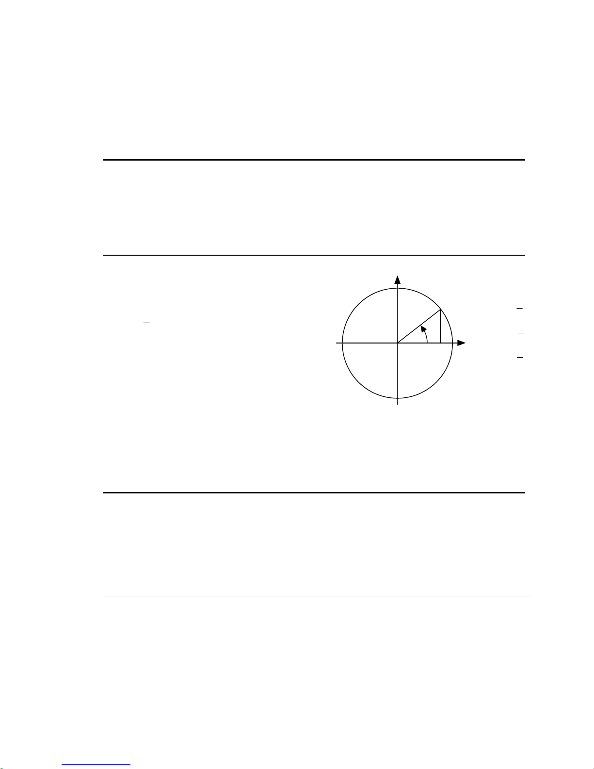
Example:
VARB1=ASX ; Extended Axis status assigned to binary variable 1
VARB2=ASX.3 ; Extended Axis status bit 3 assigned to binary variable 2
VARB2 ; Response if bit 3 is set to 1:
; "*VARB2=XX1X_XXXX_XXXX_XXXX_XXXX_XXXX_XXXX_XXXX"
IF(ASX=b101XXXXX) ; If the extended axis status contains 1's
; for bits 1 and 3, and a 0 for bit location 2, do the
; IF statement
TREV ; Transfer revision level
NIF ; End if statement
[ ATAN() ]
Type Operator (Trigonometric)
Syntax VARi=ATAN(r)
Units r = real number
Range 0.00000 to ±999,999,999
Default none
Response n/a
See Also [=], [COS], [PI], RADIAN, [SIN], [TAN], VAR
The
operator is used to calculate the inverse
ATAN
Arc Tangent
tangent of a real number. If “
Product Rev
GT6K 6.0
GV6K 6.0
y
a” and “b” are coordinates
of a point on a circle of radius “r”, then the angle of
measure “θ” can be defined by the equation:
θ=arctan
The result of the
degrees or radians, depending on the
a
.
b
command will either be in
ATAN
RADIAN
r
θ
a
b
x
command.
To convert radians to degrees, use the formula:
360° = 2π radians.
Syntax:
VARi=ATAN(r) where i is the variable number and r is a real number value. Parentheses ( ()
used with the ATAN command.
The result will be specified to 2 decimal places in either radians or
degrees.
Example:
RADIAN1 ; Enable radian mode
VAR1=ATAN(0.75) ; Set variable 1 equal to the inverse tangent of 0.75 radians
) must be
sin
cos
tan
θ =
θ =
θ =
a
r
b
r
a
b
BAUD
Type Communication Interface
Syntax BAUD<i>
Units i = Baud rate
Range i = 1200, 2400, 4800, 9600, 19200, 38400, or 115200 (COM2
Default 9600
Response BAUD *BAUD9600
See Also ADDR, E, PORT
NOTE
only)
: The baud rate for the “RS-232/485” (COM1) serial port is fixed at 9600 baud, and is not adjustable by the
Baud Rate
BAUD command.
BAUD establishes the baud rate for the “RS-232” (COM2) serial port, as selected by the last PORT command. The
default is 9600 baud (BAUD9600). The BAUD setting is automatically saved in battery backed RAM.
Changing the baud rate for the “RS-232” port will result in a loss of communication until the baud rate of the terminal
is changed accordingly.
Command Descriptions 51
www.comoso.com
Product Rev
GT6K 6.0
GV6K 6.0
NOTE
:
Page 54

Example:
PORT2 ; Select COM2 ("RS-232") port
BAUD38400 ; Set the baud rate for COM2 to 38400 baud
BOT
Type Communication Interface
Syntax <!>BOT<i>,<i>,<i>
Units n/a
Range i = 0 – 256
Default 0,0,0
Response BOT: *BOT0,0,0
See Also EOT, ERROK, ERRBAD, PORT, DRPCHK, EOL, ], [
The
command designates the characters to be placed at the beginning of every response. Up to 3
BOT
Beginning of Transmission Characters
Product Rev
GT6K 6.0
GV6K 6.0
characters can be placed before the first line of a multi-line response, or before all single-line responses.
The characters are designated with their ASCII equivalent. For example, a carriage return is ASCII 13, a
line feed is ASCII 10, a Ctrl-Z is ASCII 26, and no terminating character is designated with a zero.
NOTE: ASCII 256 transmits nothing. ASCII 256 transmits a null ASCII zero character, which is typically
used to create a null terminated string in a C language.
For a more complete list of ASCII Equivalents, refer to the ASCII Table in Appendix B.
Example:
BOT13,10,26 ; Place a carriage return, line feed, and Ctrl-Z before
; the first line of a multi-line response, and before
; all single line responses
BP
Type Program Flow Control or Program Debug Tool
Syntax <a_><!>BP<i>
Units i = break point number
Range 1 – 32
Default n/a
Response n/a
See Also BREAK, C, HALT, K, S, [ SS ], TSS
Set a Program Break Point
Product Rev
GT6K 6.0
GV6K 6.0
The BP command allows the programmer to set a place in the program where command processing will halt
and a message will be transmitted to the PC. There are 32 break points available,
transmitting the message *
BREAKPOINT NUMBER x<cr>
where x is the break point number.
BP1
to
BP32
, all
After halting at a break point, command processing can be resumed by issuing a continue (
The break point command is useful for stopping a program at specific locations in order to test status for
debugging or other purposes.
Example:
DEF prog1 ; Begin definition of program named prog1
D50000 ; Set distance to 50000 units
MA1 ; Absolute mode
GO1 ; Initiate motion
IF(PC>40000) ; Compare commanded position to 40000
BP1 ; If the motor position is > 40000 units, set break point #1
NIF ; End IF statement
D80000 ; Set distance to 80000 units
GO1 ; Initiate motion
BP2 ; Set break point #2
END ; End program definition
RUN prog1 ; Execute program prog1
If the
IF statement evaluates true, the message *BREAKPOINT NUMBER 1
command must be issued before processing will continue. Once processing has continued, the second break
52 Gemini GV6K/GT6K Command Reference
www.comoso.com
) command.
!C
will be transferred out. A !C
Page 55

point command will be encountered, again the message *
and processing of commands will pause until a second
BREAK
Type Program Flow Control
Syntax <a_><!>BREAK
Units n/a
Range n/a
Default n/a
Response n/a
See Also BP, C, GOSUB, HALT, K, S
The
command terminates program execution when processed. This command allows the user to
BREAK
Terminate Program Execution
!C
BREAKPOINT NUMBER 2
command is received.
will be transferred out,
Product Rev
GT6K 6.0
GV6K 6.0
terminate a program based upon a condition, or at any other particular point in the program where it is
necessary to end the program. If the program terminated was called from another program, control will be
passed to the calling program. This command is useful when debugging a program.
To terminate all program processing, use the
Example:
DEF prog1 ; Define a program called prog1
GO1 ; Initiate motion
GOSUB prog2 ; Gosub to subroutine named prog2
GO1 ; Initiate motion
END ; End program definition
DEF prog2 ; Define a program called prog2
D5 ; Change distance
IF(IN=b1X0) ; IF condition is: status of input 1 is active (1)
; and input 3 is inactive (0)
BREAK ; If condition is true break out of program
ELSE ; Else part of if condition
TPE ; If condition does not come true, transfer position of encoder
NIF ; End If statement
END ; End program definition
RUN prog1 ; Execute program prog1
;
; Upon completion of motion, subroutine prog2 is called. If inputs 1 and 3
; are in the correct state when the subroutine is entered, the subroutine
; will be terminated and returned to prog1, where motion will be initiated.
HALT
command.
C
Type Program Flow Control
Syntax <a_>!C
Units n/a
Range n/a
Default n/a
Response n/a
See Also BP, COMEXR, COMEXS, INFNC, PS, S
Continue Command Execution
The Continue (!C) command ends a pause state (PS), a break point (BP) condition, or a stopped (S)
condition. When the Gem6K is in a paused state or at a break point, no commands from the command
buffer are executed. All immediate commands, however, are still processed. By sending a
command processing will resume, starting with the first command after the
command. If a stop (
issuing a
Example:
PS ; Stop execution of command buffer until !C command
MA0 ; Select incremental positioning mode
D10000 ; Set distance to 10000 counts
GO1 ; Initiate motion
Command Descriptions 53
command, only if
!C
) command has been issued, motion and command processing can be resumed by
S
COMEXS
has been enabled.
www.comoso.com
Product Rev
GT6K 6.0
GV6K 6.0
!C
command or the BP
PS
command,
Page 56

No buffered commands after the PS command will be executed until a !C command is received.
!C ; Restart execution of command buffer
DEF prog1 ; Begin definition of program named prog1
D50000 ; Set distance to 50000 units
MA0 ; Select incremental positioning mode
GO1 ; Initiate motion
IF(VAR1>6) ; Compare VAR1>6
BP1 ; If the motor position is > 50000 units, set break point #1
NIF ; End IF statement
GO1 ; Initiate motion
BP2 ; Set break point #2
END ; End program definition
RUN prog1 ; Execute program prog1
If the IF statement evaluates true, the message
BREAKPOINT NUMBER 1
will be transferred out. A !C
command must be issued before processing will continue. Once processing has continued, the second break
point command will be encountered, the message
processing of commands will pause until a second
COMEXS1 ; Enable command processing on stop
D50000 ; Set distance to 50000 units
GO1 ; Initiate motion
!S ; Stop motion
BREAKPOINT NUMBER 2
command is received.
!C
will be transferred out, and
When the Gem6K drive processes the !S command, motion will be stopped. If the desired distance has not
been reached, motion can be resumed by issuing the
) command can be issued.
to stop, a Kill (
CERRLG
Type Error Handling
Syntax <a_><!>CERRLG
Units n/a
Range n/a
Default n/a
Response n/a
See Also TAS, TASX, TDHRS, TDTEMP, TERRLG, TMTEMP
The
CERRLG
!K
Clear the Error Log
command erases the stored contents of the error log. Clearing the error log is a helpful
!C command. If motion and command processing are
Product Rev
GT6K 6.0
GV6K 6.0
diagnostic tool; it allows you to start the diagnostic process when the error log is in a known state so that
you can check the error log in response to subsequent events.
The error log is updated every time an event occurs, as selected by the
command displays the last ten error conditions that the drive has experienced, as recorded in these status
registers:
(axis status binary report)
TAS
•
(extended axis status binary report)
TASX
•
(number of hours since the drive was powered up or
TDHRS
•
TDTEMP
•
TMTEMP
•
(measured temperature of the drive in centigrade)
(estimated temperature of the motor in centigrade for GV6K only; GT6K always reports
zero)
54 Gemini GV6K/GT6K Command Reference
RESET
www.comoso.com
ERRORL
)
command. The
TERRLG
Page 57

COMEXC
Type Command Buffer Control
Syntax <a_><!>COMEXC<b>
Units b = 0 or 1
Range 0 = Disable, 1 = Enable
Default 0
Response COMEXC: *COMEXC0
See Also [ ! ], A, AA, AD, ADA, COMEXL, COMEXS, D, ERRORP, FOLRD,
Use
COMEXC
(
COMEXC0
FOLRN, GO, GOWHEN, MA, MC, V
to enable or disable Continuous Command Execution Mode. Under default operation
), when a motion command is received, command processing is temporarily paused un til the
Continuous Command Processing Mode
motion is complete. In continuous command execution mode (
COMEXC1
Product Rev
GT6K 6.0
GV6K 6.0
), however, command processing
continues while motion is taking place. NOTE: Command processing will be slower and some motion
parameters cannot be changed while motion is in progress; for a complete list of motion parameters that
cannot be changed while motion is in progress, refer to the Restricted Commands During Motion section in
Chapter 1 of the Programmer's Guide.
The Continuous Command Processing Mode is useful in the following situations:
• When trying to check the status of inputs while the Gem6K is commanding motion.
• Performing calculations ahead of time, possibly decreasing cycle time.
• Executing buffered on-the-fly acceleration (
mode (
ADA, D, FOLRD, FOLRN, MA, MC
& MC), Following ratio (
MA
&
FOLRD
, or V change can be executed only with a buffered Go (GO) command.)
), and deceleration (
A, AA
), and velocity (V) changes. (The buffered A, AA, AD,
FOLRN
AD, ADA
), distance (D), positioning
For more information about on-the-fly motion changes, refer to the Programmer's Guide.
• Pre-processing the next move while the current move is in progress (see CAUTION note below). This
reduces the processing time for the subsequent move to only a few microseconds.
CAUTION: Avoid Executing Moves Prematurely
With continuous command execution enabled (
before executing the subsequent move, place a
the subsequent GO command. If you wish to ensure the load settles adequately
before the next move, use the
WAIT(AS.24=b1)
you to define end-of-move settling criteria — see
Zone section in the Programmer's Guide for details).
Example:
DEL Prog1 ; Delete program called Prog1
DEF Prog1 ; Begin definition of program called Prog1
COMEXC1 ; Enable continuous command execution mode
L50 ; Loop 50 times
D50000 ; Set distance to 50000 counts
GO1 ; Initiate motion
; Normally at this point, the Gem6K drive would wait for the motion to complete
; before processing the next command. However, with continuous command execution
; enabled (COMEXC1), processing will continue with the statements that follow.
IF(IN.1=b1) ; Check for input #1 becoming active
OUT.3-1 ; If it does, turn on output #3
ELSE ;
OUT.1-1 ; If input #1 is not on, turn on output #1
NIF
WAIT(AS.1=b0) ; Wait for no commanded motion
LN ; End loop
COMEXC0 ; Disable continuous command mode
END ; End definition of program
COMEXC1
WAIT(AS.1=bØ)
), if you wish motion to stop
statement before
command instead (this requires
STRGTE
command or the Target
Command Descriptions 55
www.comoso.com
Page 58

On-the-fly Velocity, Acceleration and Deceleration Change Example:
DEF vsteps ; Begin definition of program vsteps
COMEXC1 ; Enable continuous command execution mode
MC1 ; Set mode to continuous
A10 ; Set acceleration to 10 rev/sec/sec
V1 ; Set velocity to 1 rps
GO1 ; Initiate move
WAIT(VEL=1) ; Wait for motor to reach continuous velocity
T3 ; Time delay of 3 seconds
A50 ; Set acceleration to 50 rev/sec/sec
V10 ; Set velocity to 10 rps
GO1 ; Initiate move
T5 ; Time delay of 5 seconds
S1 ; Initiate stop of move
WAIT(MOV=b0) ; Wait for motion to completely stop
COMEXC0 ; Disable continuous command execution mode
END ; End definition of program vsteps
COMEXL
Type Command Buffer Control
Syntax <a_><!>COMEXL<b>
Units b = 0 or 1
Range 0 = Disable, 1 = Enable
Default 0
Response COMEXL: *COMEXL0
See Also COMEXC, COMEXS, ERROR, LH, LIMLVL, LS
COMEXL
(LH), or a soft limit (
determines whether the command buffer will be saved upon hitting a hardware end-of-travel limit
Continue Execution on Limit
). If save command buffer on limit is enabled (
LS
Product Rev
GT6K 6.0
GV6K 6.0
COMEXL1
), then all commands
following the command currently being executed will remain in the command buffer when a limit is hit. If
save command buffer on limit is disabled (
COMEXLØ
), then every command in the buffer will be discarded,
and program execution will be terminated.
Example:
COMEXL1 ; Save the command buffer if the limit is hit.
COMEXR
Type Command Buffer Control
Syntax <a_><!>COMEXR<b>
Units b = 0 or 1
Range 0 = disable, 1 = enable
Default 0
Response COMEXR: *COMEXR0
See Also C, COMEXS, INFNC
The
COMEXR
with the
finish executing.
command determines the functionality of programmable inputs defined as pause/continue inputs
INFNCi-E
Continue Motion on Pause/Continue Input
command. When the input is activated, the command being processed will be allowed to
Product Rev
GT6K 6.0
GV6K 6.0
COMEXRØ
: Upon receiving a pause input, only program execution is paused; any motion in progress will
continue to its predetermined destination. Releasing the pause input or issuing a
will resume program execution.
COMEXR1
: Upon receiving a pause input, both motion and program execution will be paused; the motion
stop function is used to halt motion. After motion stops, you can release the pause input or issue
command to resume motion and program execution.
a
!C
56 Gemini GV6K/GT6K Command Reference
www.comoso.com
command
!C
Page 59

Example:
COMEXR1 ; Allow both motion and program execution to be paused upon
; receiving a pause input
2INFNC1-E ; Define input 1 on I/O brick 2 as a pause/continue input
COMEXS
Type Command Buffer Control
Syntax <a_><!>COMEXS<i>
Units i = function identifier
Range 0, 1, or 2
Default 0
Response COMEXS: *COMEXS0
See Also COMEXC, COMEXL, COMEXR, INFNC, S
The
COMEXS
when the Gem6K receives a Stop command (
a stop function with
COMEXS0
command determines the impact on motion, program execution, and the command buffer
: Under factory default conditions (
S1
Continue Execution on Stop
).
, or
INFNCi-D
) or a stop input (
!S1
S, !S, S1
COMEXS0
INFNCi-D
), the following will happen:
• Motion decelerates to a stop, using the present
motion profile cannot be resumed.
• All commands in the Gem6K’s command buffer are discarded
• Program execution is terminated
COMEXS1
: Using the
COMEXS1
mode, the Gem6K allows more flexibility in responding to stop conditions,
depending on the stop method (see table below).
Stop Method
!S or S
!S1 or S1
Stop input Yes No No No Yes
Pause input *
(if COMEXR1)
Pause input *
(if COMEXR0)
* A Pause input is an input configured with the INFNCi-E command command. This is also the Resume input
that can be used to resume motion and program execution after motion is stopped
What Stops?
Program
Motion
Yes Yes Yes Yes Yes
Yes No No No Yes
Yes Yes
No Yes
Resume Motion Profile.
(Allow resume with a !C
command or a resume
input * )
Yes Yes Yes
No Yes Yes
Product Rev
GT6K 6.0
GV6K 6.0
, or
), when the Gem6K receives a stop command (S, !S,
.
) or an external Stop input (an input assigned
!S1
AD
and
deceleration values. The
ADA
.
Resume Program.
(Allow resume with a
!C command or a
resume input * )
.
Save Command Buffer.
(Save the commands that
were in the command
buffer when the stop was
commanded)
COMEXS2
: Using the
COMEXS2
exception that you can still use the program-select inputs to select programs (
retained). The program-select input functions are: BCD select (
(INFNCi-P
Command Descriptions 57
). For further details on program selection with inputs, refer to
mode, the Gem6K responds as it does in the
www.comoso.com
COMEXS0
mode, with the
INSELP
value is
INFNCi-B), and one-to-one select
and
INFNC
INSELP
.
Page 60
y
[ COS() ]
Type Operator (Trigonometric)
Syntax COS(r) (see below)
Units r = radians or degrees (depending on RADIAN command)
Range r = 0.00000 - ±17500
Default n/a
Response n/a
See Also [ ATAN ], [ PI ], RADIAN, [ SIN ], [ TAN ], VAR
Cosine
Use this operator to calculate the
cosine of a number given in radians or
degrees (see
” and “b” are coordinates of a point
a
“
RADIAN
on a circle of radius “
command). If
r”, then the angle
of measure “θ” can be defined by the
equation:
b
cos
θ=
(see illustration at right)
r
If a value is given in radians and a
conversion is needed to degrees, or
vice-versa, use the formula:
360° = 2π radians.
θ =
θ =
θ =
a
r
b
r
a
b
Product Rev
GT6K 6.0
GV6K 6.0
sin
r
a
θ
b
cos
x
tan
y = Cos x
The graph to the right
Amplitude
(y axi s)
1
shows the amplitude of
on the unit circle for
y
different values of
.
x
0.707
0
-0.707
-1
ππ
4 4
5
π
3
3
4
π
π
π
22
2π Radians = 360 Degrees
Syntax:
VARi=COS(r)
depending on the
where i is the variable number and r is a value in either radians or degrees
RADIAN
command. Parentheses (
() ) must be placed around the COS
The result will be specified to 5 decimal places.
Example:
VAR1=5 * COS(PI/4) ; Set variable 1 equal to 5 times the cosine of
; π divided by 4
7
π
4
2
π
Radians
(x ax i s )
operand.
58 Gemini GV6K/GT6K Command Reference
www.comoso.com
Page 61

D
Type Motion
Syntax <a_><!>D<r>
Units r = distance units (scalable by SCLD)
Range ±999,999,999.99999
Default 4000
Response D: *D+4000
See Also [ D ], DMEPIT, DRES, ERES, GO, IF, MA, MC, PSET, SCLD, TSTAT,
VARI, WAIT
Distance
Product Rev
GT6K 6.0
GV6K 6.0
The Distance (D) command defines either the number of units the motor will move or the absolute position
it will seek after a
command. In the incremental mode (
GO
number of units you wish the motor to move. In the absolute mode (
), the distance value represents the total
MAØ
) the distance value represents the
MA1
absolute position the motor will end up at; the actual distance traveled will vary depending on the ab solute
position of the motor before the move is initiated.
In the incremental mode (
of the distance value (e.g.,
direction without changing the distance value by using the
) is a means of toggling the direction.
tilde (
~
), you can specify a negative distance by placing a dash or hyphen (-) in front
MAØ
D-10000
). Otherwise, the direction is considered positive. You can change
, or ~ operators (e.g. D+, or
+, -
or D~); the
D-,
The distance remains set until you change it with a subsequent distance command. Distances outside the valid
range are flagged as an error, returning the message
*INVALID DATA-FIELD x
, where x is the field number.
UNITS OF MEASURE and SCALING: refer to page 16.
ON-THE-FLY CHANGES: You can change distance on the fly (while motion is in progress) in two ways.
One way is to send an immediate distance command (
The other way is to enable the continuous command execution mode (
distance command (
) followed by a buffered go command (GO).
D
) followed by an immediate go comm and (
!D
COMEXC1
) and execute a buffered
!GO
).
Direction of Motion for Rotary Motors:
Positive distance values (e.g.,
negative values (e.g.,
D-20000
D20000
assumes you connected the motor (and feedback device for serv os) according
) represent clockwise motion and
) represent counter-clockwise motion. This
Clockwise
(positive counts)
Counter-clockwise
(negative counts)
to the Hardware Installation Guide instructions.
Example:
SCALE1 ; Enable scaling
SCLA25000 ; Set the acceleration scaling factor for to 25000 steps/unit
SCLV25000 ; Set the velocity scaling factor to 25000 steps/unit
SCLD1 ; Set the distance scaling factor to 1 step/unit
DEL proga ; Delete program called proga
DEF proga ; Begin definition of program called proga
MA0 ; Incremental positioning mode
MC0 ; Preset positioning mode
A10 ; Set the acceleration to 10 units/sec/sec
AD1 ; Set the deceleration to 1 units/sec/sec
V1 ; Set the velocity to 1 units/sec
D100000 ; Set the distance to 100000 units
GO1 ; Initiate motion
END ; End definition of program called proga
Command Descriptions 59
www.comoso.com
Page 62

[ D ]
Type Assignment or Comparison
Syntax See below
Units distance units (scalable by SCLD)
Range ±999,999,999.99999
Default n/a
Response n/a
See Also D, GO, MA, MC, PSET, SCLD
Distance Assignment
Product Rev
GT6K 6.0
GV6K 6.0
The distance assignment (D) command is used to compare the programmed distance value to another value
or variable, or to assign the current programmed distance to a variable.
Syntax:
VARn=D where n
IF(D<25ØØØ)
programmed
. The D value used in any comparison, or in any assignment statement is the
value. If the actual position information is required, refer to the PC command for
D
steppers, or the
is the variable number, or
command for servos.
PE
can be used in an expression such as
[D]
UNITS OF MEASURE and SCALING: refer to page 16.
Example:
IF(D<25000) ; If the programmed distance is less than 25000 units,
; then do the statements between the IF and NIF
VAR1=D*2 ; Variable 1 = programmed distance times 2
D(VAR1) ; Set the distance to the value of variable 1
NIF ; End the IF statement
DABSD
Type Drive Configuration
Syntax <a_><!>DABSD<b>
Units b = enable bit
Range 0 (disable) or 1 (enable)
Default 0 (disabled)
Response DABSD: *DABSD1
See Also DACTDP, DDAMPA, DELVIS
The
command enables or disables the ABS damping function. ABS is a damping technique
DABSD
Enable ABS Damping
Product Rev
GT6K 6.0
GV6K n/a
(applicable only to
stepper axes)
designed for use at very low to zero speed. ABS damping requires no additional user setup or
configuration. When enabled (
(
DELVIS
) at speeds less than approximately 0.2 revs/sec (motor dependent). ABS damping can be disabled
during acceleration with the
GT6K Damping Features:
The GT6K drive provides damping features that reduce vibration, increase low-
DABSD1
DDAMPA0
), ABS damping takes precedence over electronic viscosity
command (
DDAMPA0
is the factory default setting).
speed smoothness, and decrease load settling time. (A procedure for configuring damping settings is provided
in the Configuration chapter of the Hardware Installation Guide.)
60 Gemini GV6K/GT6K Command Reference
www.comoso.com
Page 63

Command Damping Function Velocity * Default Related Parameters *
DABSD
DELVIS
DACTDP
DDAMPA
* These features are based on motor and load parameters that you set up with the configuration utility in Motion
Planner (see page 6). For optimum damping performance, accurate motor and load parameters are required.
NOTE: If you select a Parker motor with the configuration utility, all of the motor parameters (excluding LJRAT,
which sets the load-to-rotor ratio) are automatically set accordingly.
** Actual transition velocity is based on motor and load parameters, and is therefore application dependent.
ABS Damping
at extreme low speeds. This feature targets
applications that require minimal zero-speed
settling (e.g., pick-and-place applications).
Electronic Viscosity. This feature targets
applications that require reduced low-speed
velocity ripple and increased smoothness, as
well as aggressive low-speed damping.
(NOTE: If ABS Damping is enabled, it
overrides electronic viscosity in the
rev/sec
set to zero, and increase until the required
performance is achieved.
Active Damping. This feature targets
applications that require high accelerations,
fast settling at commanded speed,
mechanical vibration rejection, and highly
stable (non-resonant) motion. Start
configuration with a low DACTDP value, as
highly aggressive damping can lead to
mechanical failure.
Damping During Acceleration. When
enabled, ABS Damping and Electronic
Viscosity are allowed to function at accel and
decel rates greater than 50 revs/sec/sec. If
your application requires more responsive
acceleration and deceleration (full motor
torque) above 50 revs/sec/sec, you can
disable this feature; but be aware that doing
so increases jerk in your mechanical system.
. Load-independent damping
velocity range.) Start with DELVIS
0-0.2
0 to 0.2 revs/sec ** Disabled
0 to 3 revs/sec **
> 3 revs/sec
Affects damping at
accelerations
> 50 revs/sec/sec
Disabled
Enabled,
gain = 4
Disabled
DMTRES, DMTIND
DMTJ, DMTSTT, DPOLE,
DMTIC, DMTIND,
LJRAT
DMTJ, DMTIND,
DMTSTT, LJRAT
n/a
DACTDP
Type Drive Configuration
Syntax <a_><!>DACTDP<i>
Units i = gain
Range 0-40; 0 disables active damping
Default 4
Response DACTDP *DACTDP0
See Also DABSD, DELVIS, DMTR, LJRAT
The
DACTDP
command controls the gain of the Active Damping function for a specific motor and load.
Active Damping
Product Rev
GT6K 6.0
GV6K n/a
(applicable only to
stepper axes)
Active damping works at speeds greater than 3 revolutions per second.
NOTE: To be fully effective, the active damping function requires that you first set the system inertia ratio
(
select a Parker motor with the
configure each command listed in the
gains (calculated based on
range, but you may adjust the
An overview of the GT6K’s damping features is provided in the
Command Descriptions 61
) and configure your motor parameters. Motor parameters are automatically configured when you
LJRAT
command (if you are not using a Parker motor you must individually
DMTR
command description). With a settin g of
DMTR
and the motor parameters) give the best performance over the entire speed
LJRAT
DACTDP
setting further as your application warrants.
command description
DABSD
DACTDP20
, the nominal
www.comoso.com
Page 64

[ DAT ]
Type Data Storage
Syntax DATi
Units i = data program #
Range 1-50
Default n/a
Response n/a
See Also DATA, [ DATP ], DATPTR, DATRST, DATTCH
The
into a variable (
to the next datum for the next
Syntax:
command recalls data from the data program (
DAT
VARn=DATi where “n
or
DAT
Data Assignment
). As the data is loaded, the internal data pointer to the
VAR
DAT
” is the variable number, and “i” is the data program number,
can be used as a command argument such as
If the data is to be loaded into a command field, the
AD(DAT2)
). If the data is loaded into a variable, parentheses are not required. (e.g.,
command.
Product Rev
GT6K 6.0
GV6K 6.0
). The data is loaded into a command field, or
DATP
data increments and points
DATP
A(DAT1)
command must be placed within parentheses (e.g.,
DAT
VAR1=DAT2
). Rule of
Thumb for command value substitutions: If the command syntax shows that the command field requires a
real number (denoted by
HOMV(DAT1)
The
DAT
Example: Refer to the Reset Data Pointer (DATRST) command example.
).
command cannot be used in an expression, such as
) or an integer value (denoted by
<r>
), you can use the
<i>
IF(DAT2 < 5)
DAT
or
VAR1=1 + DAT3
substitution (e.g.,
.
DATA
Type Data Storage
Syntax <a_><!>DATA=<r>,<r>,<r>,<r>
Units r = data value
Range ±999,999,999.99999999
Default n/a
Response n/a
See Also [ DAT ], [ DATP ], DATPTR, DATRST, DATTCH, MEMORY
The
command is used only in the data programs (
DATA
Data Statement
command is followed by an equal sign (
Product Rev
GT6K 6.0
GV6K 6.0
) to identify the data statements. The
DATP
), and a maximum of four data values. The maximum number of
=
data statements is limited only by the amount of memory available.
Example: Refer to the Reset Data Pointer (DATRST) command example.
[ DATP ]
Type Data Storage
Syntax DATPi
Units i = data program number
Range 1-50
Default n/a
Response n/a
See Also [ DAT ], DATA, DATPTR, DATRST, DATSIZ, DATTCH, MEMORY
is not a command, but is the name of the program that is the default for storing data. Fifty such data
DATP
programs can be created,
Data Program
DATP1
program would be, but only the
will contain the array of data to be recalled by the
-
DATP5Ø
DATA
. The program is defined with the
and
commands are allowed within the program definition.
END
command. Upon completion of the definition, the
DATi
Product Rev
GT6K 6.0
GV6K 6.0
command, just as any other
DEF
internal data pointer is pointing to the first datum in the data program.
DATA
DATPi
62 Gemini GV6K/GT6K Command Reference
www.comoso.com
Page 65

Example:
DEF DATP5 ; Define data program 5
DATA=1,2,3,4 ; Enter data
DATA=5.62,6.52,7.12,8.47 ; Enter data
END ; End program definition
A(DAT5) ; Load data from data program 5 and store in axis acceleration.
; Axis acceleration = 1
V(DAT5) ; Load data from data program 5 and store in axis velocity.
; Axis velocity = 2
D(DAT5) ; Load data from data program 5 and store in axis distance.
; Axis distance = 3
A(DAT5) ; Load data from data program 5 and store in axis acceleration.
; Axis acceleration = 4
A(DAT5) ; Load data from data program 5 and store in axis acceleration.
; Axis acceleration = 5.62
DATPTR
Type Data Storage
Syntax <a_><!>DATPTRi,i,i
Units n/a
Range 1st i = program # 1 to 50
Default 1,1,1
Response n/a
See Also [ DAT ], DATA, [ DATP ], DATSIZ, DATTCH, [ DPTR ], TDPTR
The
DATPTR
program (
2nd i = data element # 1 to 6500
3rd i = increment setting of 1 to 100
command moves the internal data pointer to a specific data element in the specified data
DATPi
Set Data Pointer
). This command also establishes the number of data elements by which the pointer
increments after writing each data element from a
the
command.
DAT
The data program selected with the first integer in the
Subsequent
TDPTR
DATTCH, TDPTR
command to ascertain the current active data program, as well as the current location of the data
, and
pointer and the increment setting (see
The
command can be used to compare the current pointer location (the number of the data element to
DPTR
Product Rev
GT6K 6.0
GV6K 6.0
DATTCH
commands will reference the active data program. You can use the
DPTR
command description for details).
TDPTR
command, or after recalling a data element with
DATPTR
command becomes the active data program.
which the data pointer is pointing) agai nst an ot her value or variable, or to assign the pointer location
number to a variable.
As an example, suppose data program #1 (
) is configured to hold 15 data elements (
DATP1
DATSIZ1,15
the data pointer is configured to start at the first data element and increment 1 data element after every
DATTCH
assigned (
values of
value is stored (
VAR1=2, VAR2=4, VAR3=8, VAR4=64
through
VAR1
DATPTR1,1,1
will be assigned respectively to the first four data elements in the data
VAR4
program and the pointer will stop at data element #5. The response to the
), and the values of numeric variables #1 through #4 are alr e ady
). If you then enter the
DATTCH1,2,3,4
TPROG DATP1
command, the
command would
be as depicted below (the text is highlighted to illustrate the location of the data pointer after the
DATTCH1,2,3,4
*DATA=2.0,4.0,8.0,64.0
*DATA=0.0,0.0,0.0,0.0
*DATA=0.0,0.0,0.0,0.0
*DATA=0.0,0.0,0.0
command is executed). The response to the
command would be
TDPTR
*TDPTR1,5,1.
),
Once you have stored (taught) the variables to the data program, you can use the
point to the data elements and then use the
your motion program.
During the process of writing data (
element in the program, it automatically wraps around to the first datum in the program and a warning
Command Descriptions 63
data assignment command to read the stored variables to
DAT
DATTCH
) or recalling data (
www.comoso.com
DATPTR
), if the pointer reaches the last data
DAT
command to
Page 66

message is displayed (
*WARNING: POINTER HAS WRAPPED AROUND TO DATA POINT 1
). This warning will
not interrupt command execution.
Example: (See Also: DATSIZ command)
DEL DATP5 ; Delete data program #5 (DATP5)
DEF DATP5 ; Define data program #5 (DATP5)
DATA=1,2,3,4 ; Enter data
DATA=5.62,6.52,7.12,8.47 ; Enter data
END ; End program definition
A(DAT5) ; Load data from DATP5 and store in axis acceleration.
; Axis acceleration = 1
V(DAT5) ; Load data from DATP5 and store in axis velocity.
; Axis velocity = 2
D(DAT5) ; Load data from DATP5 and store in axis distance.
; Axis distance = 3
DATPTR5,1,1 ; Set the data pointer to datum 1 in DATP5; increment the
; pointer by one after each DAT command
A(DAT5) ; Load data from DATP5 and store in axis acceleration.
; Axis acceleration = 1
A(DAT5) ; Load data from DATP5 and store in axis acceleration.
; Axis acceleration = 2
DATRST
Type Data Storage
Syntax <a_><!>DATRST<i>,<i>
Units n/a
Range 1st i = program # 1 to 50, 2nd i = data element # 1 to 6500
Default n/a
Response n/a
See Also [ DAT ], DATA, [ DATP ]
The
DATRST
(
DATP<i>
command sets the internal data pointer to a specific data element in a data program
). As data is recalled from a data program with the
Reset Data Pointer
Product Rev
GT6K 6.0
GV6K 6.0
command, the pointer automatically
DAT
increments to the next data element. If the pointer reaches the end of the program, it automatically wraps
around to the first data element in the program.
the data program (
DATP
).
DATRST
allows the pointer to be set to any location within
Example:
DEF DATP5 ; Define data program 5
DATA=1,2,3,4 ; Enter data
DATA=5.62,6.52,7.12,8.47 ; Enter data
END ; End program definition
A(DAT5) ; Load data from data program 5 and store in axis acceleration.
; Axis acceleration = 1
V(DAT5) ; Load data from data program 5 and store in axis velocity.
; Axis velocity = 2
D(DAT5) ; Load data from data program 5 and store in axis distance.
; Axis distance = 3
DATRST5,1 ; Set the data pointer to datum 1 in data program 5
A(DAT5) ; Load data from data program 5 and store in axis acceleration.
; Axis acceleration = 1
A(DAT5) ; Load data from data program 5 and store in axis acceleration.
; Axis acceleration = 2
64 Gemini GV6K/GT6K Command Reference
www.comoso.com
Page 67

DATSIZ
Type Data Storage
Syntax <a_><!>DATSIZi<,i>
Units n/a
Range 1st i = program # 0 - 50 (0 = disable)
Default 0,1
Response n/a
See Also [ DAT ], DATPTR, [ DATP ], DATTCH
The
DATSIZ
2nd i = data element # 1 - 6500
command creates a new data program (
Data Program Size
Product Rev
GT6K 6.0
GV6K 6.0
) and establishes the number of data elements the
DATP
data program contains.
The
DATSIZ
command syntax is
DATSIZi<,i>
. The first integer (i) represents the number of the data
program (1 - 50). You can create up to 50 separate data programs. The data program is automatically given
a specific program name (
). If the program number Ø is selected, then the
DATPi
DATTCH
command is
disabled. Before creating a new data program, be sure to delete the existing data program that has the same
name. For example, if you wish to create data program #5 with the
already exists, first delete
DATP5
with the
DEL DATP5
command and then issue the
DATSIZ5,144
command and
DATSIZ5,144
DATP5
command.
The second integer represents the total number of data elements (up to 6,500) you want in the data
program. Upon issuing the
DATSIZ
initialized with a value of zero. (The
filling it with
DATA=Ø.Ø,Ø.Ø,Ø.Ø,Ø.Ø
command, the data program is created with all the data elements
DATSIZ
command is equivalent to creating a
program and
DATP
commands up to the size indicated in the second integer.)
Each data statement, which contains four data elements, uses 43 bytes of memory. This amount of memory
is subtracted from the memory allocated for user programs (see
MEMORY
command). Use the
TDIR
command to determine the amount of remaining memory for user program storage.
The data program has a tabular structure, where the data elements are stored 4 to a line. Each line of data
elements is called a data statement. Each element is numbered in sequential order from left to right (1 - 4)
and top to bottom (1 - 4, 5 - 8, 9 - 12, etc.). You can use the
TPROG DATPi
command ("i" represents the
number of the data program) to display all the data elements of the data program. For example, if you issue
the
DATSIZ1,13
zero. The response to the
with
DATA=
*DATA=Ø.Ø,Ø.Ø,Ø.Ø,Ø.Ø
*DATA=Ø.Ø,Ø.Ø,Ø.Ø,Ø.Ø
*DATA=Ø.Ø,Ø.Ø,Ø.Ø,Ø.Ø
*DATA=Ø.Ø
The
DATSIZ, DATTCH
1. Issue the
2. Store variable data (e.g., position, acceleration, velocity, etc.) to numeric variables (
3. Use
DATTCH
the data pointer (
the number by which the pointer increments after each value from the
NOTE: If the
command, data program #1 (called
TPROG DATP1
command is depicted below. Each line (data statement) begins
) is created with 13 data elements initialized to
DATP1
, and each data element is separated with a comma.
DATSIZ
, and
command to create (or recall) the data program.
commands will typically be used as a teach mode in this manner:
DAT
VAR
).
commands to store the data from the numeric variables into the data program. You can use
DATPTR
DATTCH
) command to select any data element in the data program, and to determine
command is stored.
command, an error will
command is issued without having issued the
DATTCH
DATSIZ
result.
4. Use the
your motion program. You can use the
program, and to determine the number by which the pointer increments after each
commands to read the stored data from the data program into the variable parameters of
DAT
DATPTR
command to select any data element in the data
command.
DAT
Any use of the
DATTCH
and
by the first integer of the last
Command Descriptions 65
commands will reference the current active data program (
DAT
DATSIZ
or
DATPTR
command. If you want to use the
www.comoso.com
DATSIZ
) specified
DATP
command to
Page 68

recall a data program, and not create one, specify only the first integer and not the second integer. For
example,
Example:
DEL DATP5 ; Delete existing data program #5 (DATP5)
DATSIZ5,200 ; Create data program #5 (DATP5) with 200 data elements
DEF TEACH ; Begin definition of program called TEACH
COMEXC0 ; Disable continuous command execution mode
MA1 ; Enable the absolute positioning mode
HOM1 ; Home (absolute position counter set to zero after homing)
DATPTR5,1,1 ; Set data pointer to data element #1 in DATP5, and increment the
; pointer by one element after every DATTCH value or DAT command
REPEAT ; Set up a loop for teaching the positions
JOY1 ; Enable joystick mode so that you can start moving the
; axis into position with the joystick. Command processing stops
; here until you activate IN.2 to disable the
; joystick mode and execute the rest of the commands in the
; repeat/until loop (assign the motor positions to the variables and
; then store the positions from the variables to the data program).
VAR1=1PM ; Store the current position in variable #1
DATTCH1 ; Store variable #1 into consecutive data elements
WAIT(IN.2=b0) ; Wait for the "joystick release" input to be de-activated
UNTIL(DPTR=1) ; Repeat loop until the data pointer wraps around to data element #1
HOM1 ; Home (absolute position counter set to zero after homing)
DATPTR5,1,1 ; Set data pointer to data element #1, read one data element at a time
REPEAT ; Set up a repeat/until loop to read all data elements
D(DAT5) ; Read position data from the data program to the distance command
GO1 ; Make the move to the positions that were taught
T.2 ; Wait 0.2 seconds
UNTIL(DPTR=1) ; Repeat loop until the data pointer wraps around to data element #1
END
DATSIZ7
; End definition of program called TEACH
recalls data program #7 (
) as the active data program.
DATP7
DATTCH
Type Data Storage
Syntax <a_><!>DATTCHi<,i,i,i>
Units i = number of a numeric variable
Range i = 1-225
Default n/a
Response n/a
See Also [ DAT ], [ DATP ],DATPTR, DATSIZ, DATTCH, VAR
The Data Teach (
Data Teach
DATTCH
) command stores the values from the specified numeric variables (
currently active data program (i.e., the data program specified with the last
command). The value that is in the specified variable at the time the
Product Rev
GT6K 6.0
GV6K 6.0
) into the
VAR
DATTCH
DATSIZ
or
DATPTR
command is executed is the
value that is stored in the data program.
If the
DATTCH
a zero is entered in the first integer of the
command is issued without having first issued the
DATSIZ
command (e.g.,
DATSIZ
DATSIZØ
command, an error will result. If
), the
DATTCH
command is
disabled.
As indicated by the number of integers in the syntax, the maximum number of variables that can be stored
in the data program per
DATTCH
command is 4. The variables are stored in the data program, starting at the
current location of the data pointer. The data pointer's position can be moved to any data element in any
data program by use of the
DATPTR
pointer will increment by the number specified in the third integer of the
command. After each successive
DATTCH
DATPTR
value is stored, the data
command. Any data
element in the data program can be edited by setting the data pointer to that element and then issuing the
DATTCH
As an example, suppose data program #1 (
command.
) is configured to hold 15 data elements (
DATP1
DATSIZ1,15
),
the data pointer is configured to start at the first data element and increment 1 data element after every
DATTCH
value is stored (
assigned (
DATPTR1,1,1
VAR1=2, VAR2=4, VAR3=8, VAR4=64
), and the values of numeric variables #1 through #4 are alr e ady
). If you then enter the
DATTCH1,2,3,4
command, the
66 Gemini GV6K/GT6K Command Reference
www.comoso.com
Page 69

values of
program and the pointer will stop at data element #5. The response to the
be as follows (the text is highlighted to illustrate the location of the data pointer after the
VAR1
through
will be assigned respectively to the first four data elements in the data
VAR4
TPROG DATP1
command would
DATTCH1,2,3,4
command is executed).
*DATA=2.Ø,4.Ø,8.Ø,64.Ø
*DATA=Ø.Ø,Ø.Ø,Ø.Ø,Ø.Ø
*DATA=Ø.Ø,Ø.Ø,Ø.Ø,Ø.Ø
*DATA=Ø.Ø,Ø.Ø,Ø.Ø
Example: Refer to the DATSIZ command.
DAUTOS
Type Drive Configuration
Syntax <a_><!>DAUTOS<r>
Units r = percent reduction of motor current
Range 0.00-99.99 : ±0.01
Default 0.00 (no current reduction)
Response DAUTOS *DAUTOS0
See Also
The
DAUTOS
command allows you to let the motor cool when it is not moving. When automatic current
Auto Current Standby
Product Rev
GT6K 6.0
GV6K n/a
(applicable only to
stepper axes)
standby is set to a value other than 0.00 (default), the motor current will be reduced by that percentage
when the drive has not issued a motion command for one second. Full commanded current is restored upon
the first motion command that the drive issues.
WARNING: Motor torque is reduced when the motor current is reduced. Applications with vertical load s
or loads that require holding torque at zero speed should not
DCLEAR
Type Display (RP240) Interface
Syntax <a_><!>DCLEARi
Units n/a
Range i = 0 (clear all lines), 1 (clear line 1), or 2 (clear line 2)
Default n/a
Response n/a
See Also DLED, DPASS, DPCUR, DSTP, DVAR, DVARB, DVARI, DWRITE
The Clear Display (
Clear Display
DCLEAR
) command clears lines (as specified with i) of the RP240 display. After clearing a
use this feature.
Product Rev
GT6K 6.0
GV6K 6.0
line, the cursor will be reset to the beginning of that line (or to the beginning of line 1 if all lines are cleared).
DCLRLR
Type Drive Configuration
Syntax <a_><!>DCLRLR
Units n/a
Range n/a
Default n/a
Response n/a
See Also DMODE, DMTLIM, DMVLIM, DIFOLD, TASX, TTRQ
status register bits 18, 19, 20 and 31 (see descriptions below) indicate conditions in which drive
TASX
Clear the Latched Status Register Bits
Product Rev
GT6K 6.0
GV6K 6.0
protective software has engaged, but drive operation continues. These status bits remain set (latched),
regardless of whether the conditions persist, and are cleared with the
a
RESET
or
DRESET
command, cycle power, or activate the Reset input.
DCLRLR
command or when you issue
Command Descriptions 67
www.comoso.com
Page 70

TASX
bit 18 Commanded Velocity Exceeds
DMVLIM
Limit (GV6K and GT6K):
Bit 18 is set when the velocity demand from the internal Gem6K control loops exceeds the
limits set by the
DMVLIM
command. The Gem6K drive responds to this condition by invoking
the “Override Mode,” in which the drive software clamps the maximum allowable velocity
command to the value set by
drive in all operating modes (
bit 19 Bridge is in Foldback Mode (GV6K only):
TASX
DMVLIM
DMODE
. The Override Mode feature is applicable to the Gem6K
).
When a GV6K drive produces more than its rated continuous current, a software algorithm
determines on an ongoing basis the amount of power being delivered by the drive to the
motor. When this value exceeds the safe threshold for the drive, the drive either goes into
Foldback Mode or faults, depending on the
the limits of the drive’s capabilities, the drive might go into Foldback Mode for a short period
of time. Bit 19 stays latched, however, so that the user can determine that foldback occurred.
bit 20 Power Dissipation Circuit Active (GV6K and GT6K):
TASX
When a Gem6K drive attempts to slow a motor down, the stored energy in the motor and load
must be absorbed by the drive. This regenerative energy will increase the bus voltage in the
drive until either a regenerative power dissipation circuit dissipates the energy or a drive overvoltage fault (reported in
bit 13) occurs. In all GT6K drives, the GV6K-L3, GV6K-H20
TASX
and GV6K-H40, internal regenerative power dissipation circuitry is provided to dissipate this
energy; when this circuitry is activated,
TASX
GV6K-U6, and GV6K-U12 drives, the external ‘Gemini Power Dissipation Module’ or
‘GPDM’ option can be used to dissipate this energy —
drives.
DIFOLD
command. For motion profiles that push
bit 20 is set and latched. In the GV6K-U3,
bit 20 does not get set for these
TASX
bit 31 Commanding Maximum Torque/Force (GV6K):
TASX
When the GV6K’s commanded torque/force reaches the limit set by
(
=
TTRQ
DDAMPA
Type Drive Configuration
Syntax <a_><!>DDAMPA<b>
Units b = enable bit
Range 0 (disable damping) or 1 (enable damping)
Default 0 disabled)
Response DDAMPA: *DDAMPA1
See Also DABSD, DELVIS
DMTLIM
Damping During Acceleration/Deceleration
When Damping During Acceleration is enabled (
Viscosity (
DELVIS
) function normally.
),
bit #31 is set. This is not considered a fault condition.
TAS
DDAMPA1
), ABS damping (
DMTLIM
DABSD
Product Rev
GT6K 6.0
GV6K n/a
(applicable only to
stepper axes)
) and Electronic
If your application requires more responsive acceleration and deceleration, you can disable Damping
During Accel/Decel with the
DDAMPA0
command (
DDAMPA0
is the factory default setting). This disables
ABS damping and Electronic Viscosity during acceleration and deceleration rates greater than 50
revs/sec/sec when the commanded speed exceeds 0.03 revs/sec.
Be aware that the
DDAMPA0
An overview of the GT6K’s damping features is provided in the
mode allows increased jerk in your mechanical system.
command descripition.
DABSD
68 Gemini GV6K/GT6K Command Reference
www.comoso.com
Page 71

DEF
Type Program or Subroutine Definition
Syntax <a_><!>DEF<t>
Units t = alpha text string (name of a program)
Range text string of 6 characters or less
Default n/a
Response n/a
See Also $, DEL, END, ERASE, GOBUF, GOSUB, GOTO, MEMORY, PCOMP, PLCP,
The
DEF
followed by 6 or fewer alpha-numeric characters. The first character may not be a number. Refer to the
DEF
MEMORY
PRUN, RUN, [ SS ], TDIR, TMEM, TPROG, TSS, TSTAT
command is the beginning of a program or subroutine definition. The syntax for the command is
command description for information on program size restriction and total number of programs
Begin Program/Subroutine Definition
Product Rev
GT6K 6.0
GV6K 6.0
possible per product.
All programs are stored in a binary fashion within the Gem6K. A program transferred back out (
after it has been defined (
), may not look identical to the program defined. However, the program is
DEF
TPROG
)
functionally identical.
NOTE
When defining a program and the memory limitation is exceeded, an error message will
be generated, and bit 11 of the system status register will be set (SS or TSS). The
program will be stored up to the point where the memory limitation was exceeded.
There is no actual difference in the definition of, or execution of a program versus the definition, or
execution of a subroutine. Both a program and a subroutine are defined as the set of commands between a
DEF<t>
and an
command. If an invalid program/subroutine name is entered, an error message will be
END
generated. An invalid program/subroutine name is any name that is also a current command. (An example
of an invalid name would be
subroutine call from the
hom1
assigned the name “
!, —, #, $, %, ^, &, *, (, ), +, -, _, =, {, }, \, |, ", :, ;, ', <, >, ,, ., ?, /
CLR
DEFhom1
HOM1
” and cannot contain any of the following characters:
, because it is impossible for the operating system to distinguish the
go home command.). A subroutine/program definition cannot be
.
The
command can be used to start executing a program/subroutine. The program name by itself can
RUN
also be used to start executing a program/subroutine. A compiled motion profile must be compiled with the
command before it can be executed with the
PCOMP
must be compiled with
The
GOTO
and
commands can be used within a program/subroutine to go to another
GOSUB
before it can be executed with the
PCOMP
command; and a compiled PLC (
PRUN
or
SCANP
PRUN
command.
PLCP
) program
program/subroutine.
) before they can be
NOTE: Program, compiled profile, or subroutine names must be deleted (
DEL
redefined.
Example:
DEL pick ; Delete program named pick
DEF pick ; Begin definition of program named pick
GO1 ; Initiate motion
END ; End program definition
RUN pick ; Execute program pick
Command Descriptions 69
www.comoso.com
Page 72

DEL
Type Program or Subroutine Definition
Syntax <a_><!>DEL<t>
Units t = alpha text string (name of a program)
Range text string of 6 characters or less
Default n/a
Response n/a
See Also $, DEF, END, ERASE, GOSUB, GOTO, RUN
The Delete a Program/Subroutine (
for the command is
command. The
ERASE
Delete a Program/Subroutine
) command removes a program or subroutine definition. The syntax
DEL
followed by 6 or fewer alpha-numeric characters. To delete all programs refer to the
DEL
command can be placed inside a program (e.g., to delete a
DEL
To edit an existing program, you must first delete it. The
Example:
DEF pick ; Begin definition of program named pick
GO1 ; Initiate motion
END ; End program definition
RUN pick ; Execute program pick
DEL pick ; Deletes program named pick
DELVIS
Type Drive Configuration
Syntax <a_><!>DELVIS<i>
Units i = gain
Range 0-7 (0 disables Electronic Viscosity)
Default 0 (disabled)
Response DELVIS *DELVIS0
See Also DACTDP, DABSD, DDAMPA, DMTR, LJRAT
When the
DELVIS
Electronic Viscosity
command is set to a non-zero value (
DEL
DELVIS1
Product Rev
GT6K 6.0
GV6K 6.0
program).
DATP
command will not delete a label ($).
Product Rev
GT6K 6.0
GV6K n/a
(applicable only to
stepper axes)
through
DELVIS7
), Electronic Viscosity
is invoked at speeds below 3 revs/sec. Electronic Viscosity is superseded by the ABS damping function
(enabled with the
DABSD1
command) at speeds below approximately 0.2 revs/sec.
If Damping During Acceleration is disabled (
accelerations greater than 50 revs/sec/sec (
DDAMPA0
DDAMPA0
An overview of the GT6K’s damping features is provided in the
), Electronic Viscosity is disabled during
is the factory default setting).
command descripition.
DABSD
NOTE: To be fully effective, the electronic viscosity function requires that you first set the system inertia
ratio (
) and configure your motor parameters. Motor parameters are automatically configured when
LJRAT
you select a Parker motor with the configuration tool in Motion Planner (if you are not using a Parker
motor you must individually configure each command listed in the
setting of
DELVIS5
performance over the entire speed range, but you may adjust the
, the nominal gains (calculated based on
LJRAT
DELVIS
command description). With a
DMTR
and the motor parameters) give the best
setting further as your application
warrants.
70 Gemini GV6K/GT6K Command Reference
www.comoso.com
Page 73

DHALL
Type Drive Configuration
Syntax <a_><!>DHALL<i>
Units i = control option #
Range 0 (Enable Hall Error Checking)
Default 0
Response DHALL: *DHALL0
See Also SHALL, THALL, TASX
1 (Disable Hall Error Checking)
Disable Hall Sensor Checking
Product Rev
GT6K n/a
GV6K 6.0
(applicable only to
servo axes)
NOTE: When issued, this command takes effect immediately.
Encoder Motors (with
SFB1
): The
DHALL
command controls whether or not the Hall error checking
routines are invoked once the Gemini drive determines a valid absolute position of the motor at
initialization.
These error routines include checks:
1. to see if all three Hall sensors are reporting valid states (000 and 111 are not valid).
2. to see if the Hall state signal order is correct for either positive (clockwise) or negative
(counter clockwise) motion. The Hall state order is 6, 2, 3, 1, 5, 4, 6, 2, 3, 1, 5, 4, 6 (and
so on) for a motor turning in the positive direction.
3. to see if the encoder reports a position that is within +/- 90 electrical degrees from the Hall
sensor reading.
If any or all of these three conditions are not met for more than 40 consecutive samples, the drive will fault
with BIT21 of
TASX
set.
NOTE: At start up, the Hall signals are used to determine the initial position of the rotor with an accuracy
of +/- 30 electrical degrees regardless of how
DHALL
is set. Once the motor begins to rotate and after it
passes through another valid Hall state, the motor commutation sequence switches over to using the
encoder only and therefore no longer requires the use of the Hall sensors. At this point a check is made to
DHALL
see if
is set to 0 (Hall checking on) or 1 (Hall checking off.)
For a complete description on how to troubleshoot Hall sensors, especially for non-Compumotor motors,
refer to the Hardware Installation Guide section on using non-Compumotor motors.
Resolver Motors (with
DIBW
Type Tuning
Syntax <a_><!>DIBW<i>
Units i = Hz
Range 0-5000 (motor dependent)
Default 0 (DIBW of 0 results in motor configuration error)
Response DIBW: *DIBW1000
See Also DMTLIM, DMTSCL, DMVLIM, DNOTAF, DNOTAQ, DNOTLD, DNOTLG, DPBW,
AUTO-SETUP:
configuration utility in Motion Planner (see page 6). If you did not use the configuration utility or are not using a
Parker Motor, this command is set to zero and you will have to manually set this parameter. (Refer to DMTR
for a list of auto-configured commands.) If the drive is powered up when this command is set to zero (for
instance, if RFS is executed), the drive reports a motor configuration error with TASX bit 7, writes –32259 to
TCS, and shuts down the drive (DRIVE0).
SGIRAT, TASX, TCS, TGAIN, TSGSET
SFB4
): If you use a resolver motor,
Current Loop Bandwidth
This command is automatically set according to the Parker motor selected with the
DHALL
is not applicable.
Product Rev
GT6K n/a
GV6K 6.0
(applicable only to
servo axes)
Command Descriptions 71
www.comoso.com
Page 74
The
command sets the bandwidth of the current loop, in hertz. The drive current will be progressively
DIBW
less responsive to inputs or disturbances above this frequency. Fast, short moves may require higher
settings, while systems with mechanical resonance may require lower settings, or the use of filters (see
DNOTAF, DNOTAQ, DNOTBF, DNOTBQ, DNOTLD, DNOTLG
).
Low current loop bandwidth can limit the bandwidth and stiffness that can be attained in the velocity and
position loops. High bandwidths can emphasize resonance and system noise, add to heating of both motor
and drive, and increase acoustic noise produced by the motor.
NOTE: Attempting to set this value too low for the selected motor will result in a motor configuration
error. This will set
bit #7 and write error -32259 in the
TASX
configuration status register.
TCS
Working with servo gains.
• Servo tuning process: refer to the Hardware Installation Guide.
• Check the values of all active gains (
• Creating and invoking gain sets: see
DIFOLD
Type Drive Configuration
Syntax <a_><!>DIFOLD<b>
Units b = enable bit
Range 0 (disable) or 1 (enable)
Default 0
Response DIFOLD: *DIFOLD0
See Also
The
DIFOLD
command enables (1) or disables (0) the drive’s current foldback protection feature. The current
Current Foldback Enable
is one of many servo gains): use
DIBW
SGSET, SGENB, TGAIN, TSGSET
.
TGAIN.
Product Rev
GT6K n/a
GV6K 6.0
(applicable only to
servo axes)
foldback feature reduces the drive’s continuous current output by 20% when sustained current has the
potential to overheat the drive.
Each drive has the following specifications. Note that current ratings are for the drive, not for the motor.
Units GV6K-L3 GV6K-U3 GV6K-U6 GV6K-U12 GV6K-H20 GV6K-H40
Drive Continuous Current Rating (100%) amps * 3 3 6 12 20 40
Drive Peak Current Rating** amps * 7.5 7.5 15 30 50 100
Maximum Time at Peak Current Rating
* peak of the sinewave
** peak rating is 250% of continuous rating
seconds 6 6 6 6 6 6
If your drive is operating above its continuous rating, use the figur e below to predict the number of seconds
until foldback will occur. For example, the figure shows that at the drive’s peak current rating (250% of
continuous), foldback will occur after six seconds.
Drive Current Rating vs. Time
Peak Rating = 250 %
200 %
150 %
Continuous Rating = 100 %
50 %
0
1 10 100 10
Time (seconds)
3
10
4
72 Gemini GV6K/GT6K Command Reference
www.comoso.com
Page 75

DIGN
Type Tuning
Syntax <a_><!>DIGNc<r>
Units c = gain identifier letter (required);
Range c = A, B, C, or D;
Default r = 0.000 (DIGNc of 0 results in motor config. warning)
Response DIGNA: *DIGNA2.306
See Also DMTR, TASX, TCS
AUTO-SETUP:
configuration utility in Motion Planner (see page 6). If you did not use the configuration utility or are not using a
Parker Motor, this command is set to zero and you will have to manually set this parameter. (Refer to DMTR for
a list of auto-configured commands.) If the drive is powered up when this command is set to zero (for instance,
if RFS is executed), the drive reports a motor configuration warning with TASX bit 28, and writes a value to the
TCS register (46 for DIGNA, 47 for DIGNB, 48 for DIGNC, or 49 for DIGND).
Use the
r = gain value
DIGNA, DIGNB, DIGNC : r = 0.000 to 15.000 : ±0.001
DIGND : r = 0.000 to 1.000 : ±0.001
command to set values for the gain terms in the stepper current loop, which optimizes drive
DIGN
Current Loop Gain
This command is automatically set according to the Parker motor selected with the
Product Rev
GT6K 6.0
GV6K n/a
(applicable only to
stepper axes)
performance for a specific motor.
Setting
DIGN
values for Non-Parker Motors:
NOTES
The drive must be disabled (DRIVE0) before making any changes to the DIGN values.
•
• When making changes to DIGNA, DIGNB and DIGNC values, the ratio between the
values must remain constant. That is, multiply or divide all three gain values by the same
amount.
• Increasing the DIGN values can improve system performance; however, setting an
excessive DIGN value will cause the motor to “sing” (emit a high-pitched squeal or
screech) when it is at rest and to heat unnecessarily
Calculating initial values * :
DIGNA =
DIGNB = DIGNA * 0.0896
DIGNC = DIGNA * 0.3578
DIGND = 0.98 (this value will not be changed again)
Inductance (in mH)
2
* If these initial values cause the motor to “sing,” immediately disable the drive (
DIGNC
and lower
DIGNA, DIGNB
and
If motor performance is not as high as expected, increase
by the same factor; repeat as necessary.
DIGNA, DIGNB
and
DIGNC
(keeping the initial ratio) until system performance is acceptable.
For additional assistance in determining
DJOG
Type Display (RP240) Interface
Syntax <a><!>DJOG<b>
Units b = 0 or 1
Range 0 = disable, 1 = enable
Default 0
Response DJOG: *DJOG0
See Also JOG, JOGA, JOGAA, JOGAD, JOGADA, JOGVH, JOGVL
The
command allows you to branch into the RP240 front panel jog mode from within your user-
DJOG
Enable RP240 Jog Mode
values for your motor, please consult the factory.
DIGNc
defined program, adjust the position of the axis, and then return to program execution.
DRIVE0
)
by the same factor
Product Rev
GT6K 6.0
GV6K 6.0
Command Descriptions 73
www.comoso.com
Page 76

The
RP240 arrow keys to jog the axis. Unlike the
DJOG1
with the Jog Acceleration (
the Jog Velocity High (
command enables the RP240 jog mode. Once the RP240 jog mode is enabled, you can use the
DJOG1
command, command processing is suspended after the
JOG
command is issued. Jogging acceleration and deceleration are performed with the parameters set
) and Jog Deceleration (
JOGA
) and the Jog Velocity Low (
JOGVH
) commands. Jogging velocities are set with
JOGAD
) commands. Once in the RP240 Jog
JOGVL
Mode, you can switch between low and high jog velocities, and you can also modify the two jog velocities
EDIT
using the RP240's
To disable the RP240 jog mode, press the
key.
MENU RECALL
key or issue the immediate
!DJOGØ
command.
Upon exiting the RP240 jog mode, the RP240's display is cleared.
To have the jog mode continually enabled during program execution, you must use jog inputs and the
JOG
command.
[ DKEY ]
Type Display (RP240) Interface; Assignment or Comparison
Syntax See below
Units n/a
Range n/a
Default n/a
Response n/a
See Also DCLEAR, DPCUR, [ DREAD ], DREADF, DREADI, DVAR, DWRITE
The
commands (e.g.,
simultaneously,
operator allows you to read the current state of the RP240 key-pad and use it in comparison
DKEY
Value of RP240 Key
IF, WHILE
DKEY
, etc.) or variable assignments. NOTE: If two or more keys are pressed
will report -1.
Product Rev
GT6K 6.0
GV6K 6.0
Syntax:
VARn=DKEY where “n
or
can be used in an expression such as
DKEY
The value reported by the
Value of DKEY
-1 None or multiple keys
0 0
1 1
2 2
3 3
4 4
5 5
6 6
7 7
8 8
9 9
10 .
11 +/12 C/E
13 ENTER
14 Menu Recall
15 STOP
16 PAUSE
17 CONTINUE
21 F1
22 F2
23 F3
24 F4
25 F5
26 F6
” is the variable number,
IF(DKEY=-1)
command is defined by the following table:
DKEY
Key currently active
74 Gemini GV6K/GT6K Command Reference
www.comoso.com
Page 77
DLED
Type Display (RP240) Interface
Syntax <a_><!>DLED<b><b><b><b><b><b><b><b>
Units n/a
Range b = 0 (off) or 1 (on)
Default n/a
Response DLED: *DLED1101_0001
See Also DCLEAR, DPASS, DPCUR, DSTP, DVAR, DVARB, DVARI, DWRITE
The
command controls the state of the 8 programmable LEDs on the RP240. It is legal to substitute a
DLED
binary variable (
Example:
DLED11XXXX01 ; Turn on LEDs 1, 2, and 8; turn off LED 7; leave LEDs 3,4,5,
; and 6 unchanged
VARB1=b10101010 ; Set bits 1, 3, 5 & 7 low, and bits 2, 4, 6, & 8 high
DLED(VARB1) ; Turn on LEDs 1, 3, 5 & 7; turn off LEDs 2, 4, 6, & 8
DMEPIT
Type Motor (Linear only)
Syntax <a_><!>DMEPIT<r>
Units r = millimeters
Range 0 to 327.68 : ±0.01
Default 0
Response DMEPIT: *DMEPIT40.00
See Also D, DRES, ERES
cycle power
Turn RP240 Display LEDs On/Off
VARB
) for the
Motor Electrical Pitch
DLED
command.
(does not take effect until RESET, DRESET or
)
Product Rev
GT6K 6.0
GV6K 6.0
Product Rev
GT6K n/a
GV6K 6.0
(applicable only to
servo axes)
NOTE: This command is only applicable if you use the Motion Planner Setup Wizard, which uses the
DMEPIT
value to convert linear units to rotary units before downloading commands to the drive. The drive
always expects rotary units. If you are not using the Motion Planner Setup Wizard, this command is not
applicable, and you must convert your linear units to rotary units.
AUTO-SETUP:
configuration utility in Motion Planner (see page 6). If you did not use the configuration utility or are not using a
Parker linear servo motor, this command is set to 0 and assumes a rotary motor. Refer to DMTR for a list of
auto-configured commands. For more information on linear motion, see the Programmer’s Guide.
The
DMEPIT
This command is automatically set according to the Parker motor selected with the
command sets the electrical pitch
Linear motor track
of the magnets for use with permanent magnet
brushless linear motors. The
DMEPIT
required to convert between linear units and
rotary units. The electrical pitch can equated to
value is
N S
N S
N S
N S
one revolution in a rotary motor. Mechanically,
the definition of the electrical pitch is the linear
distance between two magnets comprising a
full magnetic cycle. The illustration shows an
example of an electrical pitch of 42mm
(
DMEPIT42
For all rotary motors,
).
DMEPIT
is set to zero.
42 mm
Definition of DMEPIT (Electrical Pitch)
Converting Between Rotary and Linear Values
The Gem6K drive operates in rotary units; therefore, it expects to receive commands in rotary units and
reports operating conditions in rotary units. The setup wizard in Motion Planner (page 6) makes it easy to
perform the setup in linear units. The setup wizard automatically converts your setup parameters (in linear
units) to the appropriate Gem6K code in rotary units. You then download the generated code/file to the
drive. If you are communicating to the Gem6K over a live serial link, you must convert certain command
values from linear to rotary units before you send them to the drive. Likewise, when you query the drive for
Command Descriptions 75
www.comoso.com
Page 78

2
2
certain conditions, or if you upload the configuration file from the drive, the command values are reported
in rotary units.
Use the following table as a guide.
Command/Parameter To convert rotary to linear,
DMTKE (motor voltage constant)
DMTW (motor rated speed)
DMVLIM (velocity limit)
SMVER (max. allowable velocity error)
TACC (display commanded accel)
TVEL (display commanded velocity)
TVELA (display actual velocity)
TVE (display velocity error)
Velocity & Accel/Decel (e.g., V, A, AD)
DMTD (motor damping)
DMTJ (motor/forcer mass)
LDAMP (load damping)
DMTLIM (force limit)
DMTSCL (force scaling)
multiply by:
60
DMEPIT
DMEPIT
1000
(
2
• π •
(
DMEPIT
2
• π •
DMEPIT
1000
)
1000
)
2
To convert linear to rotary,
multiply by:
DMEPIT
DMEPIT
(
DMEPIT
(
2
• π •
60
1000
)
1000
2
)
DMEPIT
2
1000
• π •
If you are constructing your own motor data files, use the formulas from the table below. The key
conversion parameter is r and is defined as:
DMEPIT mm
r
()
π=⋅
2 1000
General Motion Equation
Position
Velocity
Acceleration
Force / Torque
Mass / Inertia
Damping
Flux constant
Linear Motor Convert to rotary units
FMaDv=+ TJ Bαω=+
xm=
v =
a =
m
sec
sec
m
2
x
θ= =
ω= =
α= =
radians
r
v radians
sec
r
a radians
2
sec
r
FN= TFrNm=⋅=
22
=⋅ =
Nm
2
radians
sec
2 1000
_
π
60
K
e linear
Dm=
_
=
kgM
N
sec
V
−
φφ
,
peak
=
m
Jmr kgm
BDr
=⋅=
=⋅ ⋅ =
KrK
e e Linear
sec
V
,
peak
krpm
−
φφ
76 Gemini GV6K/GT6K Command Reference
www.comoso.com
Page 79

DMODE
Type Drive Configuration
Syntax <a_><!>DMODE<i>
Units i = control mode setting
Range 1-17 (see table below)
Default 12
Response DMODE: *DMODE12
See Also DRES, SRSET
Use the
DMODE
Drive Control Mode
command to select the drive control mode for your Gem6K drive. Refer to the table below
Product Rev
GT6K 6.0
GV6K 6.0
for drive mode descriptions and drive compatibility.
Mode Description GT6K GV6K
DMODE
1 – 10 RESERVED ---------------- -- -11 Feedback Alignment Mode (requires a resolver card to be installed)
12 Controller/Drive
— default for GT6K & GV6K drives
13 Autorun Rotates the motor at 1 rps/mps. Current is reduced by
14 RESERVED ---------------- -- -15 Torque/Force Tuning Mode 10 Hz step input of 25% rated motor current for
16 Velocity Tuning Mode
17 Position Tuning Mode
* Refer to the servo tuning procedures in the Hardware Installation Guide for details.
This mode allows you to automatically set the resolver
offset angle with the SRSET command.
Programmed motion using internal trajectory generator. X X
10%. Refer also to the Hardware Installation Guide.
torque/force mode tuning. *
1 Hz ±2 rps/mps step velocity command for velocity
mode tuning. *
1 Hz ± 1/4 rev/epitch step position command for position
mode tuning. *
-- X
X X
-- X
-- X
-- X
DMONAS
Type Outputs
Syntax <a_><!>DMONAS<i>
Units i = scale percentage (%)
Range -2000 to 2000
Default 100 (no scaling)
Response DMONAS: *DMONAS100
See Also DMONAV, DMONBS, DMONBV
The
DMONAS
For example,
command sets the amount by which the variable selected with the
Analog Monitor Output A — Scaling
DMONAS200
doubles the amplitude of the selected output signal. The maximum scaled output
voltage is approximately ±10V.
Monitor waveform clipping will occur if
DMONAS
Product Rev
GT6K 6.0
GV6K 6.0
DMONAV
scaling results in an output greater than ±10V.
command is scaled.
Command Descriptions 77
www.comoso.com
Page 80

DMONAV
Type Outputs
Syntax <a_><!>DMONAV<i>
Units i = variable number
Range 0-24 (0 = turn off output)
Default 0 (turn off output)
Response DMONAV: *DMONAV0
See Also DMEPIT, DMONAS, DMONBS, DMONBV
The
DMONAV
terminal (pin 21 on the
Number Name Description GT6K GV6K
0 Unused / Turn off output No output function selected X X
1
2 Drive Temperature
3 Position Error
4 Velocity Setpoint
5 Estimated Actual Velocity
6 Acceleration Setpoint
7 Torque/Force Setpoint
8 Actual Torque/Force
9 Velocity Error
10 Phase A Commanded
11 Phase A Actual Current Instantaneous measured current for phase A (Volts per Amp). *
command selects the function (or signal) that will be presented at the 8-bit DAC “
Motor Temperature
Current
Analog Monitor Output A — Variable
DRIVE I/O
connector).
(TMTEMP) Estimated motor winding temperature based on a
second-order thermal model (see the Hardware Installation Guide
for details). Normalized to ±10 volts equals ±250
(TDTEMP) Measured internal drive temperature. Normalized to
±10 volts equals ±250
This value is normalized as follows (value clips at ±1 rev or
±1 electrical pitch, regardless of the DMONAS setting):
• Rotary motors: ±10V = ±1 rev (based on TPER ÷ ERES)
• Linear motors: ±10V = ±1 epitch (based on TPER ÷ DMEPIT)
(TVEL) User commanded velocity. Normalized to ±10 volts
equals ±200 revs/sec (rotary) or ±8.4 meters/sec (linear).
(TVELA) Output of velocity estimator, based on encoder or
resolver data. Normalized to ±10 volts equals ±200 revs/sec
(rotary) or ±8.4 meters/sec (linear).
(TACC) User commanded acceleration.
(TTRQ) User commanded torque/force.
(TTRQA) Calculated torque/force based on measured motor
current and motor Ke (DMTKE). Scaled as a % of DMTSCL.
(TVE) Normalized to ±10 volts equals ±200 revs/sec (rotary) or
±8.4 meters/sec (linear).
Instantaneous commanded current for phase A (Volts per Amp). *
o
C.
Product Rev
GT6K 6.0
GV6K 6.0
Analog Out A
o
C.
X
X
X X
X
X
X X
”
X
X
X
X
X
X
X
78 Gemini GV6K/GT6K Command Reference
www.comoso.com
Page 81

Number Name Description GT6K GV6K
13 Phase B Actual Current Instantaneous measured current for phase B (Volts per Amp). *
14 RESERVED
15 RESERVED
16 d-axis Commanded
17 d-axis Actual Current Estimated direct-axis current from coordinate-conversion
18 q-axis Commanded
19 q-axis Actual Current Estimated quadrature-axis current from coordinate-conversion
20 Phase A Applied Voltage
21 Phase B Applied Voltage
22 RESERVED
23 Position Setpoint
24 Actual Position
* The nominal Volts per Amp scaling is drive dependent, and is shown below:
Current
Current
Duty Cycle
Duty Cycle
Commanded direct-axis current (usually 0). This current does not
produce torque/force. *
software. Based on measured phase currents. *
Commanded quadrature-axis current. This current is proportional
to commanded torque/force. *
software. Based on measured phase currents. This current is
proportional to actual torque/force. *
A voltage representation of the PWM duty cycle for Phase A.
A voltage representation of the PWM duty cycle for Phase B.
This value is normalized as follows (value clips at ±1 rev or
±1 electrical pitch (epitch), regardless of the DMONAS setting):
• Rotary motors: ±10V = ±1 rev (based on TPC ÷ ERES)
• Linear motors: ±10V = ±1 epitch (based on TPC ÷ DMEPIT)
This value is normalized as follows (value clips at ±1 rev or
±1 electrical pitch, regardless of the DMONAS setting):
• Rotary motors: ±10V = ±1 rev (based on TPE ÷ ERES)
• Linear motors: ±10V = ±1 epitch (based on TPE ÷ DMEPIT)
X X
X
X
X
X
X
X
X
X
Stepper
Drive
GT6K-L5 1.432 GV6K-L3 0.615
GT6K-L8
GV6K-U6 0.308
GV6K-U12 0.205
GV6K-H20 0.123
DMONBS
Type Outputs
Syntax <a_><!>DMONBS<i>
Units i = scale percentage (%)
Range -2000 to 2000
Default 100 (no scaling)
Response DMONBS: *DMONBS100
See Also DMONAS, DMONAV, DMONBV
The
DMONBS
command sets the amount by which the variable selected with the
Nominal (V/A)
Current Scaling
0.882
Analog Monitor Output B — Scaling
GV6K-U3 0.615
Servo
Drive
GV6K-H40
Nominal (V/A)
Current Scaling
0.062
The maximum scaled output voltage is ±10V.
Monitor waveform clipping will occur if
DMONBS
scaling results in an output greater than ±10V.
DMONBV
Product Rev
GT6K 6.0
GV6K 6.0
command is scaled.
Command Descriptions 79
www.comoso.com
Page 82

DMONBV
Type Outputs
Syntax <a_><!>DMONBV<i>
Units i = variable number
Range 0-24 (0 = turn off output)
Default 0 (turn off output)
Response DMONBV: *DMONBV0
See Also DMONAS, DMONAV , DMONBS
The
DMONBV
terminal (pin 22 on the
Number Name Description GT6K GV6K
0 Unused / Turn off output No output function selected X X
1
2 Drive Temperature
3 Position Error
4 Velocity Setpoint
5 Estimated Actual Velocity
6 Acceleration Setpoint
7 Torque/Force Setpoint
8 Actual Torque/Force
9 Velocity Error
10
11 Phase A Actual Current Instantaneous measured current for phase A (Volts per Amp). * X X
12 Phase B Commanded Current Instantaneous commanded current for phase B (Volts per Amp).
13 Phase B Actual Current Instantaneous measured current for phase B (Volts per Amp). * X X
14 RESERVED
15 RESERVED
16 d-axis Commanded Current Commanded direct-axis current (usually 0). This current does
17 d-axis Actual Current Estimated direct-axis current from coordinate-conversion
18 q-axis Commanded Current Commanded quadrature-axis current. This current is
19 q-axis Actual Current Estimated quadrature-axis current from coordinate-conversion
20 Phase A Applied Voltage Duty
21 Phase B Applied Voltage Duty
22 RESERVED
command selects the function (or signal) that will be presented at the 8-bit DAC “
Motor Temperature
Phase A Commanded Current Instantaneous commanded current for phase A (Volts per Amp).
Cycle
Cycle
Analog Monitor Output B — Variable
DRIVE I/O
connector).
(TMTEMP) Estimated motor winding temperature based on a
second-order thermal model (see the Hardware Installation
Guide for details). Normalized to ±10 volts equals ±250
(TDTEMP) Measured internal drive temperature. Normalized to
±10 volts equals ±250
This value is normalized as follows (value clips at ±1 rev or
±1 electrical pitch, regardless of the DMONAS setting):
• Rotary motors: ±10V = ±1 rev (based on TPER ÷ ERES)
• Linear motors: ±10V = ±1 epitch (based on TPER ÷ DMEPIT)
(TVEL) User commanded velocity. Normalized to ±10 volts
equals ±200 revs/sec (rotary) or ±8.4 meters/sec (linear).
(TVELA) Output of velocity estimator, based on encoder or
resolver data. Normalized to ±10 volts equals ±200 revs/sec
(rotary) or ±8.4 meters/sec (linear).
(TACC) User commanded acceleration.
(TTRQ) User commanded torque/force.
(TTRQA) Calculated torque/force based on measured motor
current and motor Ke (DMTKE). Scaled as a % of DMTSCL.
(TVE) Normalized to ±10 volts equals ±200 revs/sec (rotary) or
±8.4 meters/sec (linear).
*
*
not produce torque/force. *
software. Based on measured phase currents. *
proportional to commanded torque/force. *
software. Based on measured phase currents. This current is
proportional to actual torque/force. *
A voltage representation of the PWM duty cycle for Phase A.
A voltage representation of the PWM duty cycle for Phase B.
Product Rev
GT6K 6.0
GV6K 6.0
Analog Out B
o
C.
o
C.
(Continued on next page)
X
X
X X
X
X
X
X
X
X
”
X
X
X
X
X
X
X
X
X
X
80 Gemini GV6K/GT6K Command Reference
www.comoso.com
Page 83

Number Name Description GT6K GV6K
23 Position Setpoint
24 Actual Position
* The nominal Volts per Amp scaling is drive dependent, and is shown below:
This value is normalized as follows (value clips at ±1 rev or
±1 electrical pitch (epitch), regardless of the DMONAS setting):
• Rotary motors: ±10V = ±1 rev (based on TPC ÷ ERES)
• Linear motors: ±10V = ±1 epitch (based on TPC ÷ DMEPIT)
This value is normalized as follows (value clips at ±1 rev or
±1 electrical pitch, regardless of the DMONAS setting):
• Rotary motors: ±10V = ±1 rev (based on TPE ÷ ERES)
• Linear motors: ±10V = ±1 epitch (based on TPE ÷ DMEPIT)
X
X
Stepper
Drive
GT6K-L5 1.432 GV6K-L3 0.615
GT6K-L8
GV6K-U6 0.308
GV6K-U12 0.205
GV6K-H20 0.123
DMTAMB
Type Motor
Syntax <a_><!>DMTAMB<r>
Units r = Degrees Celsius
Range -50.0 to 250.0 : ±0.1
Default 40.0
Response DMTAMB: *DMTAMB40.0
See Also DMTMAX, DMTRWC, DMTTCM, DMTTCW, TASX
The
DMTAMB
DMTAMB
constant (
command sets the motor ambient temperature used by the software motor thermal model. The
value, in conjunction with the motor thermal time constant (
DMTTCW
Nominal (V/A)
Current Scaling
0.882
Motor Ambient Temperature
), the motor thermal resistance (
GV6K-U3 0.615
Servo
Drive
GV6K-H40
Nominal (V/A)
Current Scaling
0.062
), the motor winding time
DMTRWC
DMTTCM
) and the continuous motor current (
Product Rev
GT6K n/a
GV6K 6.0
(applicable only to
servo axes)
), is
DMTIC
used in a real-time estimation of the motor winding temperature. When the winding temperature exceeds
DMTMAX
, the drive faults and
bit #30 is set.
TASX
NOTE: If you cycle power, or issue a
RESET
or
DRESET
command, the drive resets its motor thermal
model (in internal software). Be aware that your motor’s winding temperature may still be high.
DMTD
Type Motor
Syntax <a_><!>DMTD<r>
Units Rotary motor: r = Nm/rad/sec
Range Rotary motor: 0.000000 to 0.010000 : ±0.000001
Default 0.000000
Response DMTD: *DMTD0.002000
See Also DMTR, LDAMP
cycle power
Linear motor: r = N/meter/sec
Linear motor: DMEPIT (electrical pitch) dependent
Motor Damping
)
NOTE: This command does not take effect until you cycle power to the drive, or issue a RESET
(does not take effect until RESET, DRESET or
Product Rev
GT6K n/a
GV6K 6.0
(applicable only to
servo axes)
or
DRESET
command.
Command Descriptions 81
www.comoso.com
Page 84

AUTO-SETUP:
configuration utility in Motion Planner (see page 6). If you did not use the configuration utility or are not using a
Parker Motor, this command is set to zero and you will have to manually set this parameter. (Refer to DMTR
for a list of auto-configured commands.)
The
DMTD
bearing losses. (The load
DMTIC
Type Motor
Syntax <a_><!>DMTIC<r>
Units r = Amps-RMS
Range 0.00 to 100.00 : ±0.01
Default 0.00 (DMTIC of 0 results in motor configuration warning)
Response DMTIC: *DMTIC6.50
See Also DMTICD, TASX, TCS, TDICNT
This command is automatically set according to the Parker motor selected with the
command specifies the damping of the motor itself. This includes both magnetic losses and
damping is specified with the
Continuous Current
LDAMP
command.)
Product Rev
GT6K 6.0
GV6K 6.0
GV6K Only: This command does not take effect until you cycle power to the drive, or issue a RESET
DRESET
command.
GT6K Only: This command takes effect immediately.
AUTO-SETUP:
configuration utility in Motion Planner (see page 6). If you did not use the configuration utility or are not using a
Parker Motor, this command is set to zero and you will have to manually set this parameter. (Refer to DMTR
for a list of auto-configured commands.) If the drive is powered up when this command is set to zero (for
instance, if RFS is executed), the drive reports a motor configuration warning with TASX bit 28, and writes 40
to TCS.
This command is automatically set according to the Parker motor selected with the
or
The
command sets the continuous operating current for a motor. For a servo drive operating a rotary
DMTIC
motor continuously at this current, the internal winding temperature will reach 125°C with a specified
heatsink (see the Gemini Motor Reference Manual for heatsink dimensions) in a 40°C ambient. For linear
servo motors, the winding will reach 90°C in a 25°C ambient.
The continuous current of a motor that is designed to provide a long service life depends on many factors.
Among them are motor ambient temperature, the degree of heatsinking provided by the motor mounting
surface, and airflow over the motor. In a stepper, the continuous current is flowing in the motor
continuously. In a servo, the continuous current is used in calculations to protect the motor from thermal
damage, and has no immediate effect on performance.
Example:
DMTIC5 ; Set the motor current to 5 amps rms (equates to 7.07 amps peak)
DMTICD
Type Motor
Syntax <a_><!>DMTICD<i>
Units i = percent derating at rated speed
Range 0.00 to 100.00 : ±0.01
Default 0.00 (DMTICD of 0 results in no current derating)
Response DMTICD: *DMTICD5
See Also DMTIC, DMTIP, DMTW
cycle power
Continuous Current Derating
)
(does not take effect until RESET, DRESET or
NOTE: This command does not take effect until you cycle power to the drive, or issue a RESET
Product Rev
GT6K n/a
GV6K 6.0
(applicable only to
servo axes)
or
DRESET
command.
82 Gemini GV6K/GT6K Command Reference
www.comoso.com
Page 85

AUTO-SETUP:
configuration utility in Motion Planner (see page 6). If you did not use the configuration utility or are not using a
Parker Motor, this command is set to zero and you will have to manually set this parameter. (Refer to DMTR
for a list of auto-configured commands.)
The
DMTICD
This command is automatically set according to the Parker motor selected with the
command sets the percentage current derati n g at rate d spee d (
). This value sets the extent
DMTW
to which continuous current must be reduced at speed to compensate velocity-related losses in the motor.
For example,
DMTIC
DMTICD3
) at the motor’s rated speed (
DMTIND
Type Motor
Syntax <a_><!>DMTIND<r>
Units r = mH
Range 0.0 to 200.0 : ±0.1
Default 0.0 (DMTIND of 0 results in motor config. error)
Response DMTIND *DMTIND10
See Also DMTLMN, DMTLMX, DMTR, TASX, TCS
NOTE: This command does not take effect until you cycle power to the drive, or issue a RESET
cycle power
sets the motor’s continuous current derating to 3% (or 97% of continuous value
). At half this speed, it will be reduced 1.5%.
DMTW
Motor Inductance
)
(does not take effect until RESET, DRESET or
Product Rev
GT6K 6.0
GV6K n/a
(applicable only to
stepper axes)
or
DRESET
command.
AUTO-SETUP:
configuration utility in Motion Planner (see page 6). If you did not use the configuration utility or are not using a
Parker Motor, this command is set to zero and you will have to manually set this parameter. (Refer to DMTR
for a list of auto-configured commands.) If the drive is powered up when this command is set to zero (for
instance, if RFS is executed), the drive reports a motor configuration error with TASX bit 7, writes a value of
-32726 to the TCS register, and shuts down the drive (DRIVE0).
This command is automatically set according to the Parker motor selected with the
The
DMTIND
set with
command sets the motor phase inductance for stepper motors only (servo motor inductance is
DMTLMN
and
DMTLMX
). The motor inductance entered is the motor phase inductance you measure
across one phase at the motor terminals of the drive. The inductance value is the “small signal inductance”
as measured by a hand-held or bench-top inductance meter at 1 KHz.
A procedure for configuring motor inductance (for non-Parker motors) is provided in the Configuration
chapter of the Hardware Installation Guide.
DMTIP
Type Motor
Syntax <a_><!>DMTIP<r>
Units r = Amps-RMS
Range 0.00 to 128.00 : ±0.01
Default 0.00 (DMTIP of 0 results in motor config. warning)
Response DMTIP: *DMTIP7.50
See Also DMTIC, DMTICD, DMTLIM, DMTR, TASX, TCS, TDIMAX
AUTO-SETUP:
configuration utility in Motion Planner (see page 6). If you did not use the configuration utility or are not using a
Parker Motor, this command is set to zero and you will have to manually set this parameter. (Refer to DMTR
for a list of auto-configured commands.) If the drive is powered up when this command is set to zero (for
instance, if RFS is executed), the drive reports a motor configuration warning with TASX bit 28, and a value of
51 is written to the TCS configuration status register.
The
command sets a limit that the commanded current cannot exceed. This is typically set to three
DMTIP
Peak Current
This command is automatically set according to the Parker motor selected with the
times the motor’s continuous current rating (
Product Rev
GT6K n/a
GV6K 6.0
(applicable only to
servo axes)
) or less.
DMTIC
Command Descriptions 83
www.comoso.com
Page 86

If
value will be ignored (but not overwritten), the configuration warning (
51 is written to the
internally. The configuration warning is cleared with the
is set higher than the full-scale value calculated by
DMTIP
configuration status register, and the full-scale
TCS
DMTLIM
RESET
(torque/force limit) the new
bit #28) will be set, a value of
TASX
value will be used
command or by cycling power
or
DMTLIM
DRESET
DMTIP
to the drive.
If the
value exceeds the drive’s maximum output current (
DMTIP
TDIMAX
), the
value will be ignored
DMTIP
and the maximum allowable value will be used (see table below).
Units GV6K-L3 GV6K-U3 GV6K-U6 GV6K-U12 GV6K-H20 GV6K-H40
Maximum Current Rating amps * 7.5 7.5 15 30 50 100
* peak of the sinewave
Note that the values in
TDIMAX
are amps (peak of the sine wave) and the value for
is in amps (rms).
DMTIP
They are related by:
I
I
rms
DMTJ
Type Motor
Syntax <a_><!>DMTJ<r>
Units Rotary motor: r = kgm
Range Rotary motor: 0.000 to 1000000.000 : ±0.001
Default 0.000 (DMTJ of 0 results in motor config. error)
Response DMTJ: *DMTJ200.600
See Also DMTR, TASX, TCS
cycle power
Linear motor: r = kg
Linear motor: DMEPIT (electrical pitch) dependent
Motor Rotor Inertia / Forcer Mass
(does not take effect until RESET, DRESET or
)
2
* 10-6
NOTE: This command does not take effect until you cycle power to the drive, or issue a RESET
peak of the sine wave
=
2
Product Rev
GT6K 6.0
GV6K 6.0
or
DRESET
command.
AUTO-SETUP:
configuration utility in Motion Planner (see page 6). If you did not use the configuration utility or are not using a
Parker Motor, this command is set to zero and you will have to manually set this parameter. (Refer to DMTR
for a list of auto-configured commands.) If the drive is powered up when this command is set to zero (for
instance, if RFS is executed), the drive reports a motor configuration error with TASX bit 7, writes a value of
-32710 to the TCS register, and shuts down the drive (DRIVE0).
The
DMTJ
DMTKE
Type Motor
Syntax <a_><!>DMTKE<r>
Units Rotary motor: r = volts (0-peak)/krpm (measured line-to-line)
Range Rotary motor: 0.0 to 400.0 : ±0.1
Default 0.0 (DMTKE of 0 results in motor config. error)
Response DMTKE: *DMTKE15.0
See Also DMEPIT, DMONAV, DMONBV, DMTSCL, DMTR, TASX, TCS
NOTE: This command does not take effect until you cycle power to the drive, or issue a RESET
This command is automatically set according to the Parker motor selected with the
command sets the motor rotor inertia for rotary motors, or the forcer mass for linear motors.
Motor Ke
power)
Linear motor: r = volts (0-peak)/meter/sec (measured line-to line)
Linear motor: DMEPIT (electrical pitch) dependent
(does not take effect until RESET, DRESET or cycle
Product Rev
GT6K n/a
GV6K 6.0
(applicable only to
servo axes)
or
DRESET
command.
84 Gemini GV6K/GT6K Command Reference
www.comoso.com
Page 87
AUTO-SETUP:
configuration utility in Motion Planner (see page 6). If you did not use the configuration utility or are not using a
Parker Motor, this command is set to zero and you will have to manually set this parameter. (Refer to DMTR
for a list of auto-configured commands.) If the drive is powered up when this command is set to zero (for
instance, if RFS is executed), the drive reports a motor configuration error with TASX bit 7, writes a value of
-32727 to the TCS register, and shuts down the drive (DRIVE0).
The
DMTKE
motor selected with the
This command is automatically set according to the Parker motor selected with the
command specifies the motor voltage constant (Ke). This defaults to the nominal Ke of the
command.
DMTR
The motor’s torque/force constant (Kt) is derived from the motor’s voltage constant (Ke) by the following
relationship:
Rotary motors:
)/(
*
value peak
33
=
200
π
**
)/(*
krpmVoltsKeANmKt
Linear motors:
)/(
*
value peak
33
=
200
π
**
meterVoltsKeANKt
sec))//((*
NOTE: The Gem6K requires values in rotary units. Motion Planner does these conversions for you when
you use the Setup Wizard. If you do not use the Setup Wizard, you must convert your linear units to rotary
units. See the
DMEPIT
command for information on conversion.
DMTLIM
Type System
Syntax <a_><!>DMTLIM<r>
Units Rotary motor: r = Nm
Range Rotary motor: 0.0 to 500.0 (motor/drive dependent) : ±0.1
Default 0
Response DMTLIM: *DMTLIM10.5
See Also DCLRLR, DMEPIT, DMODE, DMTIP, DMTKE, DMTR, DMTSCL, TASX,
AUTO-SETUP:
configuration utility in Motion Planner (see page 6). If you did not use the configuration utility or are not using a
Parker Motor, this command is set to zero and you will have to manually set this parameter. Refer to DMTR for
a list of auto-configured commands.
The
DMTLIM
Linear motor: r = N
Linear motor: DMEPIT (electrical pitch) dependent
TGAIN, TSGSET, TTRQ, TTRQA
command sets a maximum torque/force limit for the system. Requests for higher torque/force
Torque/Force Limit
This command is automatically set according to the Parker motor selected with the
Product Rev
GT6K n/a
GV6K 6.0
(applicable only to
servo axes)
will be clamped to this value. This command will default automatically to a value appropriate to the motor
selection (
) and the GV6K drive you are using, and no changes are required in many cases.
DMTR
If your mechanical system has torque/force limitations (due, for example, to the limitations of a coupler or
belt), you can use this command to limit system torque/force without affecting system scaling or gains.
During initial tuning, this command can be used to limit the torque/force produced if the system becomes
unstable.This reduces the rate of motor heating, allows more reaction time for the person tuning the system,
and lessens chances of damage to the mechanical system.
When the GV6K’s commanded torque/force reaches the limit set by
bit #31 is set.
RESET
DMTLIM
or
DRESET
is set higher than the value allowed by the motor’s peak current times the motor’s Kt, or the
a
If
bit #31 remains set until you clear it with the
TASX
. This is not considered a fault condition.
drive’s peak current times the motor’s Kt (whichever is lower), the new
Command Descriptions 85
www.comoso.com
DMTLIM (TTRQ
DCLRLR
command, cycle power, or issue
DMTLIM
=
DMTLIM
),
TASX
value will be ignored (but
Page 88

not overwritten), the status warning bit #28 in
used. This warning is cleared with the
RESET
will be set, and the maximum internal value will be
TASX
or
DRESET
command or by cycling power to the drive.
The motor’s torque/force constant (Kt) is derived from the motor’s voltage constant (Ke, which is set by
the
command) by the following relationship (note:
DMTKE
Rotary motors:
*
peak value
)/(
Ke is set with the DMTKE command
33
=
200
π
**
):
)/(*
krpmVoltsKeANmKt
Linear motors:
*
peak value
33
=
)/( meterVoltsKeANKt
200
π
**
sec))//((*
NOTE: The
Gem6K requires values in rotary units. Motion Planner does these conversions for you when you use the
Setup Wizard. If you do not use the Setup Wizard, you must convert your linear units to rotary units. See
the
DMEPIT
command for information on conversion.
Working with servo gains.
• Servo tuning process: refer to the Hardware Installation Guide.
• Check the values of all active gains (
• Creating and invoking gain sets: see
DMTLIM
SGSET, SGENB, TGAIN, TSGSET
is one of many servo gains): use
.
TGAIN.
DMTLMN
Type Motor
Syntax <a_><!>DMTLMN<r>
Units r = mH (measured line-to-line)
Range 0.1 to 200.0 (motor dependent) : ±0.1
Default 0.0 (DMTLMN of 0 results in motor config. error)
Response DMTLMN: *DMTLMN10.0
See Also DMTLMX, DMTR, TASX, TCS
cycle power
Minimum Motor Inductance
)
(does not take effect until RESET, DRESET or
NOTE: This command does not take effect until you cycle power to the drive, or issue a RESET
Product Rev
GT6K n/a
GV6K 6.0
(applicable only to
servo axes)
or
DRESET
command.
AUTO-SETUP:
configuration utility in Motion Planner (see page 6). If you did not use the configuration utility or are not using a
Parker Motor, this command is set to zero and you will have to manually set this parameter. (Refer to DMTR
for a list of auto-configured commands.) If the drive is powered up when this command is set to zero (for
instance, if RFS is executed), the drive reports a motor configuration error with TASX bit 7, writes a value of
-32715 to the TCS register, and shuts down the drive (DRIVE0).
The
DMTLMN
This command is automatically set according to the Parker motor selected with the
command specifies the minimum value of motor inductance. This will usually differ from the
nominal nameplate value because actual inductance is usually position dependen t.
If
DMTLMN
error is reported in
Units GV6K-L3 GV6K-U3 GV6K-U6 GV6K-U12 GV6K-H20 GV6K-H40
Lmin (min. phase-phase inductance) mH 0.5 5.0 5.0 5.0 5.0 5.0
value is less than the “Lmin” value (see table below), the drive will fault (motor configuration
bit #7).
TASX
86 Gemini GV6K/GT6K Command Reference
www.comoso.com
Page 89

DMTLMX
Type Motor
Syntax <a_><!>DMTLMX<r>
Units r = mH (measured line-to-line)
Range 0.1 to 200.0 (motor dependent) : ±0.1
Default 0.0 (DMTLMX of 0 results in motor config. error)
Response DMTLMX: *DMTLMX10.0
See Also DMTLMN, DMTR, TASX, TCS
power)
Maximum Motor Inductance
(does not take effect until RESET, DRESET or cycle
NOTE: This command does not take effect until you cycle power to the drive, or issue a RESET
Product Rev
GT6K n/a
GV6K 6.0
(applicable only to
servo axes)
or
DRESET
command.
AUTO-SETUP:
configuration utility in Motion Planner (see page 6) . If you did not use the configuration utility or are not using
a Parker Motor, this command is set to zero and you will have to manually set this parameter. (Refer to DMTR
for a list of auto-configured commands.) If the drive is powered up when this command is set to zero (for
instance, if RFS is executed), the drive reports a motor configuration error with TASX bit 7, writes a value of
-32714 to the TCS register, and shuts down the drive (DRIVE0).
The
DMTLMX
This command is automatically set according to the Parker motor selected with the
command specifies the maximum value of motor inductance. This will usually differ from the
nominal nameplate value since actual inductance is usually position dependent.
DMTMAX
Type Motor
Syntax <a_><!>DMTMAX<r>
Units r = Degrees Celsius
Range -50.0 to 250.0 : ±0.1
Default 125.0
Response DMTMAX: *DMTMAX125.0
See Also DMTAMB, DMTIC, DMTRWC, DMTTCM, DMTTCW, TASX
AUTO-SETUP:
configuration utility in Motion Planner (see page 6). If you did not use the configuration utility or are not using a
Parker Motor, you will have to manually set this parameter. (Refer to DMTR for a list of auto-configured
commands.)
Maximum Motor Winding Temperature
This command is automatically set according to the Parker motor selected with the
Product Rev
GT6K n/a
GV6K 6.0
(applicable only to
servo axes)
The
DMTMAX
command sets the maximum motor winding temperature allowed. The
conjunction with the motor thermal time constant (
the motor thermal resistance (
estimation of the motor winding temperature. When the winding temperature exceeds
faults and
bit #30 is set.
TASX
NOTE: If you cycle power, or issue a
model (in internal software). Be aware that your motor’s winding temperature may still be high.
Command Descriptions 87
DMTRWC
DMTTCM
), the motor winding time constant (
) and the continuous motor current (
RESET
or
DRESET
command, the drive resets its motor thermal
www.comoso.com
DMTMAX
), is used in a real-time
DMTIC
DMTMAX
value, in
DMTTCW
, the drive
),
Page 90

DMTR
Type Drive Configuration
Syntax <a_><!>DMTR<i>
Units i = Parker motor identification number
Range 0-3000 (0 = non-Parker motor; 1-3000 = Parker motor)
Default -1 (motor config. Parameters are not configured)
Response DMTR: *DMTR50
See Also (see parameter table below), DRIVE, RESET, RFS, TASX, TCS
The purpose of the
Identify (and Load) Motor
command is to record and report the identification number of the Parker motor
DMTR
Product Rev
GT6K 6.0
GV6K 6.0
you selected in the setup tool in Motion Planner (see page 6).
When you select a specific Parker motor using the Motion Planner setup tool, the
setting and various
DMTR
motor parameters (see list below) are automatically configured for the associated motor and saved in a
configuration file. After you download the configuratio n file to the Gem6K drive, you must cycle drive
power, or issue a
effect. (NOTE: If you do not select a Parker motor, the default setting,
all relevant motor parameters manually.) Av oi d using the
because the new
or
RESET
DMTR
DRESET
value may not represent the actual motor parameters that are currently loaded in the
command for the
and all the motor parameter commands to take
DMTR
DMTR-1
command to change the motor number,
DMTR
, is used and you must set
drive. Instead, use the Motion Planner setup tool to change the motor number.
Stepper Motor Data Parameters Servo Motor Data Parameters
DIGNA.......Current Loop Gain A
DIGNB.......Current Loop Gain B
DIGNC.......Current Loop Gain C
DIGND.......Current Loop Gain D
DMTIC.......Continuous Current
DMTIND.....Motor Inductance
DMTJ .........Motor Rotor Inertia
DMTRES.....Motor Winding Resistance
DMTSTT.....Motor Static Torque
DMVLIM.....Velocity Limit
DPOLE.......Number of Motor Pole Pairs
Although these command values are auto-configured when you select a Parker motor (using the setup tool in Motion Planner), you may
individually set the command values with the respective configuration command.
DIBW ..........Current Loop Bandwidth DMTSCL ....Torque/Force Scaling
DMEPIT ......Motor Electrical Pitch DMTTCM.... Motor Thermal Time Constant
DMTD ..........Motor Damping DMTTCW ....Motor Winding Time Constant
DMTIC ........ Continuous Current DMTW ........Motor Rated Speed
DMTICD ......Continuous Current Derating DMVLIM ....Velocity Limit
DMTIP ........ Peak Current DPBW ........ Position Loop Bandwidth
DMTJ ..........Motor Rotor Inertia DPOLE ...... Number of Motor Pole Pairs
DMTKE ........Motor Ke DRES ........Drive Resolution
DMTLIM ......Torque/Force Limit ERES ........ Encoder Resolution
DMTLMN ......Minimum Motor Inductance ORES ........ Encoder Output Resolution
DMTLMX ......Maximum Motor Inductance SFB........... Feedback Source Selection
DMTMAX ......Maximum Motor Winding Temp. SRSET ...... Resolver Offset Angle
DMTRES ......Motor Winding Resistance
DMTRWC ......Motor Winding Thermal Resistance
Motor Configuration Error
For many of the above motor parameters, if they are not configured (i.e., a command is left at its factory default
value, or an RFS command is executed) when the Gem6K drive is powered up, a motor configuration “error” or
“warning” is reported in TASX bit #7 or bit #28 (an “error” also disables the drive – DRIVE0). To resolve the error or
warning condition, you must select a Parker motor with Motion Planner (or configure each motor parameter
command with a value other than zero – using a Gem6K terminal emulator), download the resulting configuration
information and then cycle power, or issue the RESET or DRESET command.
Updating the motor data table. The motor information for the parameters list above is located in a file
named “GEM_motors.mtr” and is used by Motion Planner to configure the Gem6K drive. Updates to this file
are maintained on the Compumotor web site (
http://www.compumotor.com
) — search for “GEM_motors.mtr”.
If you need to update the information, download the latest motor table file. If you are using Motion Planner,
place the updated file in the Motion Planner directory (default location is
Planner
).
88 Gemini GV6K/GT6K Command Reference
\Program Files\Compumotor\Motion
www.comoso.com
Page 91

DMTRES
Type Motor
Syntax <a_><!>DMTRES<r>
Units r = Ohm (measured line-to-line)
Range 0.00 to 50.00 : ±0.01
Default 0.00 (DMTRES of 0 results in motor config. error)
Response DMTRES: *DMTRES7.50
See Also DMTR, TASX, TCS
cycle power
Motor Winding Resistance
)
(does not take effect until RESET, DRESET or
NOTE: This command does not take effect until you cycle power to the drive, or issue a RESET
Product Rev
GT6K 6.0
GV6K 6.0
or
DRESET
command.
AUTO-SETUP:
configuration utility in Motion Planner (see page 6). If you did not use the configuration utility or are not using a
Parker Motor, this command is set to zero and you will have to manually set this parameter. (Refer to DMTR
for a list of auto-configured commands.) If the drive is powered up when this command is set to zero (for
instance, if RFS is executed), the drive reports a motor configuration error with TASX bit 7, writes a value of
-32725 to the TCS register, and shuts down the drive (DRIVE0).
The
DMTRES
drive end
of the motor cable (motor cable included). For steppers, this resistance is a phase resistance
This command is automatically set according to the Parker motor selected with the
command sets the motor winding resistance. This resistance value is measured at 25 °C at the
measured at terminals A+ to A-, or B+ to B-. For servos, this resistance is the phase-to-phase resistance
measured at termnals U to V, V to W, or W to U.
NOTE: Disconnect the motor cable from the drive before attempting to make this measurement. For best
accuracy, and to avoid injury, this measurement must be made with the motor cable disconnected from the
drive.
DMTRWC
Type Motor
Syntax <a_><!>DMTRWC<r>
Units r = Degrees Celsius/Watt (°C/W)
Range 0.00 to 50.00 : ±0.01
Default 0.00
Response DMTRWC: *DMTRWC23.60
See Also DMTR, DMTTCM, DMTTCW, TASX, TCS
cycle power
Motor Winding Thermal Resistance
)
(does not take effect until RESET, DRESET or
NOTE: This command does not take effect until you cycle power to the drive, or issue a RESET
Product Rev
GT6K n/a
GV6K 6.0
(applicable only to
servo axes)
or
DRESET
command.
AUTO-SETUP:
configuration utility in Motion Planner (see page 6). If you did not use the configuration utility or are not using a
Parker Motor, this command is set to zero and you will have to manually set this parameter. (Refer to DMTR
for a list of auto-configured commands.)
DMTRWC
specifies the temperature rise of the motor winding above motor case temperature per watt of
winding power dissipation. Motor heatsinking does not affect this value. See the
This command is automatically set according to the Parker motor selected with the
DMTMAX
command for
more information on how the drive estimates motor temperature.
Command Descriptions 89
www.comoso.com
Page 92

DMTSCL
Type Drive Configuration
Syntax <a_><!>DMTSCL<r>
Units Rotary motor: r = Nm
Range Rotary motor: 0.0 to 500.0 (motor/drive dependent) : ±0.1
Default 0
Response DMTSCL: *DMTSCL20.0
See Also DMEPIT, DMONAV, DMONBV, DMTKE, DMTLIM, TTRQ, TTRQA
AUTO-SETUP:
configuration utility in Motion Planner (see page 6). If you did not use the configuration utility or are not using a
Parker Motor, this command is set to zero and you will have to manually set this parameter. (Refer to DMTR
for a list of auto-configured commands.)
The
DMTSCL
will set the
full-scale
Linear motor: r = N
Linear motor: DMEPIT (electrical pitch) dependent
command scales the torque/force (
DMTSCL
DMTSCL
Torque/Force Scaling
This command is automatically set according to the Parker motor selected with the
value according to the Parker motor you select. If you use a non-Parker motor, set the
value according to the peak torque/force your motor can produce (in newton-meters for
Product Rev
GT6K n/a
GV6K 6.0
(applicable only to
servo axes)
TTRQ
and
). Motion Planner’s configuration utility
TTRQA
rotary motors, or newtons for linear motors.
DMTLIM
may limit torque/force to less than this full-scale value.
NOTE: The Gem6K requires values in rotary units. Motion Planner does these conversions for you when
you use the Setup Wizard. If you do not use the Setup Wizard, you must convert your linear units to rotary
units. See the
DMEPIT
command for information on conversion.
DMTSTT
Type Drive Configuration
Syntax <a_><!>DMTSTT<i>
cycle power
Units i = oz-in
Range 0 to 5000
Default 0 (DMTSTT of 0 results in motor config. error)
Response DMTSTT *DMTSTT410
See Also DMTR, TASX, TCS
Motor Static Torque
)
(does not take effect until RESET, DRESET or
NOTE: This command does not take effect until you cycle power to the drive, or issue a RESET
Product Rev
GT6K 6.0
GV6K n/a
(applicable only to
stepper axes)
or
DRESET
command.
AUTO-SETUP:
configuration utility in Motion Planner (see page 6). If you did not use the configuration utility or are not using a
Parker Motor, this command is set to zero and you will have to manually set this parameter. (Refer to DMTR
for a list of auto-configured commands.) If the drive is powered up when this command is set to zero (for
instance, if RFS is executed), the drive reports a motor configuration error with TASX bit 7, writes a value of
-32729 to the TCS register, and shuts down the drive (DRIVE0).
The
DMTSTT
This command is automatically set according to the Parker motor selected with the
command sets the motor static torque. The motor static torque is the motor holding torque
measured in the “one phase on” condition. The “one phase on” condition is measured with the peak motor
current in one phase.
90 Gemini GV6K/GT6K Command Reference
www.comoso.com
Page 93

DMTTCM
Type Motor
Syntax <a_><!>DMTTCM<r>
Units r = minutes
Range 0.0 to 300.0 : ±0.1
Default 0.0
Response DMTTCM: *DMTTCM30.4
See Also DMTR, DMTTCW
cycle power
Motor Thermal Time Constant
)
(does not take effect until RESET, DRESET or
NOTE: This command does not take effect until you cycle power to the drive, or issue a RESET
Product Rev
GT6K n/a
GV6K 6.0
(applicable only to
servo axes)
or
DRESET
command.
AUTO-SETUP:
configuration utility in Motion Planner (see page 6). If you did not use the configuration utility or are not using a
Parker Motor, this command is set to zero and you will have to manually set this parameter. (Refer to DMTR
for a list of auto-configured commands.)
The
DMTTCM
This command is automatically set according to the Parker motor selected with the
command specifies the thermal time constant of the motor and its mounting. This value is
used to help protect the motor from thermal damage. It describes the length of time the motor takes to reach
63% of it’s final temperature, given constant power. Note that motor mounting will affect this.
Continuous current ratings and published time constants for Parker motors are specified when mounted to a
10" x 10" x ¼" aluminum plate in 25 °C free air. If your mounting surface provides heatsinking or thermal
mass significantly different than this, a different value may be appropriate to your application. Note also
that the time constant of the motor winding itself (
DMTTCW
winding temperature will initially be much faster than
) is much faster than this; therefore, the rise in
DMTTCM
would suggest.
DMTTCW
Type Motor
Syntax <a_><!>DMTTCW<r>
Units r = minutes
Range 0.00 to 100.00 : ±0.01
Default 0.00
Response DMTTCW: *DMTTCW28.40
See Also DMTMAX, DMTR, DMTTCM, DMTRWC
cycle power
Motor Winding Time Constant
)
(does not take effect until RESET, DRESET or
NOTE: This command does not take effect until you cycle power to the drive, or issue a RESET
Product Rev
GT6K n/a
GV6K 6.0
(applicable only to
servo axes)
or
DRESET
command.
AUTO-SETUP:
configuration utility in Motion Planner (see page 6). If you did not use the configuration utility or are not using a
Parker Motor, this command is set to zero and you will have to manually set this parameter. (Refer to DMTR
for a list of auto-configured commands.)
The
DMTTCW
This command is automatically set according to the Parker motor selected with the
command specifies the time constant of the motor winding alone. This is the time for the
winding to reach 63% of it’s final temperature rise above the rest of the motor, given constant power. Note
that this is NOT the time constant usually specified in motor data sheets (see
DMTTCM
); the
DMTTCW
value is
typically much faster.
Command Descriptions 91
www.comoso.com
Page 94
DMTW
Type Motor
Syntax <a_><!>DMTW<r>
Units Rotary motor: r = revs/sec
Range Rotary motor: 0.0 to 200.0 : ±0.1
Default 0.0 (DMTW of 0 results in motor config. error)
Response DMTW: *DMTW150.0
See Also DMEPIT, DMTICD, DMTR, TASX, TCS
cycle power
Linear motor: r = meters/sec
Linear motor: DMEPIT (electrical pitch) dependent
Motor Rated Speed
(does not take effect until RESET, DRESET or
)
NOTE: This command does not take effect until you cycle power to the drive, or issue a RESET
Product Rev
GT6K n/a
GV6K 6.0
(applicable only to
servo axes)
or
DRESET
command.
AUTO-SETUP:
configuration utility in Motion Planner (see page 6). If you did not use the configuration utility or are not using a
Parker Motor, this command is set to zero and you will have to manually set this parameter. (Refer to DMTR
for a list of auto-configured commands.) If the drive is powered up when this command is set to zero (for
instance, if RFS is executed), the drive reports a motor configuration error with TASX bit 7, writes a value of
-32718 to the TCS register, and shuts down the drive (DRIVE0).
The
DMTW
This command is automatically set according to the Parker motor selected with the
command specifies the rated speed of the motor. This is the lesser of:
• (rotary motor) The motor mechanical limit of 7500 RPM (125 rps)
• (rotary motor) The encoder limit of 6000 rpm (100 rps) for a 1000-line encoder
• Linear motor speed limitations include encoder resolution and track length.
• The corner of the continuous speed/torque or speed/force curve (the point where the continuous
torque/force breaks downward).
The
value is used in conjunction with
DMTW
DMTICD
to protect the motor from thermal damage.
NOTE: The Gem6K requires values in rotary units. Motion Planner does these conversions for you when
you use the Setup Wizard. If you do not use the Setup Wizard, you must convert your linear units to rotary
units. See the
DMEPIT
DMVLIM
Type System
Syntax <a_><!>DMVLIM<r>
Units Rotary motor: r = revs/sec
Range Rotary motor: GT6K: 0.000000 to 60.000000 : ±0.000001
Default GT6K: 50.000000
Response DMVLIM: *DMVLIM50.000000
See Also DCLRLR, DMODE, DMTR, SGVRAT, TASX, TGAIN, TSGSET
AUTO-SETUP:
configuration utility in Motion Planner (see page 6). If you did not use the configuration utility or are not using a
Parker Motor, this command is set to zero and you will have to manually set this parameter. Refer to DMTR for
a list of auto-configured commands.
The
DMVLIM
Linear motor: r = meters/sec
GV6K: 0.000000 to 200.000000 : ±0.000001
Linear motor: DMEPIT (electrical pitch) dependent
GV6K: 200.000000
command sets a limit that commanded velocity cannot exceed, without affecting gains or
command for information on conversion.
Velocity Limit
This command is automatically set according to the Parker motor selected with the
Product Rev
GT6K 6.0
GV6K 6.0
scaling. This is typically used to protect parts of the mechanical system.
In controller/drive mode (
DMODE12
If the velocity demand from the internal Gem6K control loops exceeds the limits set by
bit 18 will be set. The Gem6k responds to this condition by invoking the “Override Mode,” in which the
92 Gemini GV6K/GT6K Command Reference
),
DMVLIM
clamps the command to the specified value.
DMVLIM
www.comoso.com
, then
TASX
Page 95
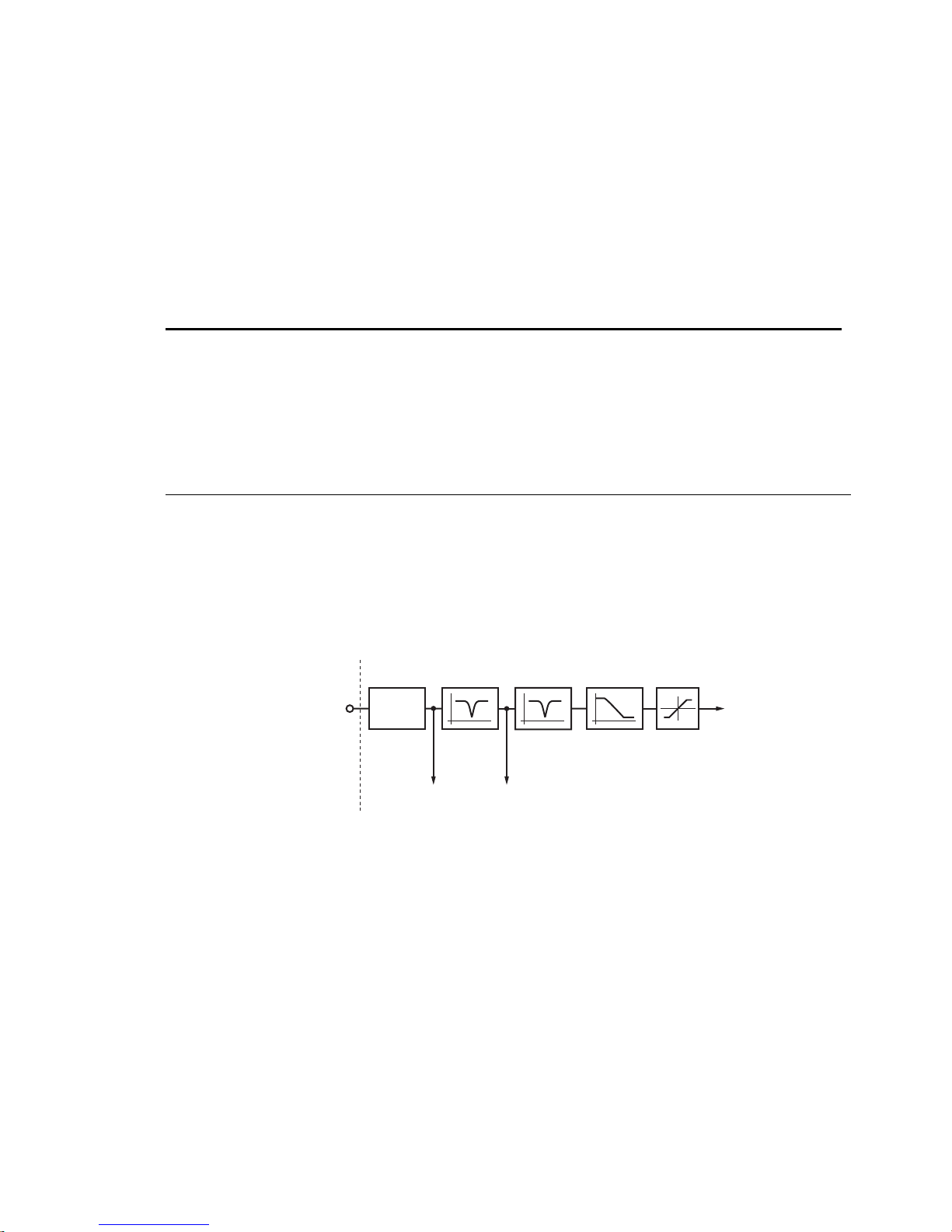
drive software clamps the maximum allowable velocity command to the value set by
latched until a
Changes to the
DCLRLR, RESET
DMVLIM
command are not allowed while motion is in progress.
or
DRESET
is issued.
DMVLIM
. Bit 18 stays
NOTE: The Gem6K requires values in rotary units. Motion Planner does these conversions for you when
you use the Setup Wizard. If you do not use the Setup Wizard, you must convert your linear units to rotary
units. See the
DMEPIT
command for information on conversion.
Working with servo gains.
• Servo tuning process: refer to the Hardware Installation Guide.
• Check the values of all active gains (
• Creating and invoking gain sets: see
DNOTAD
Type Tuning
Syntax <a_><!>DNOTAD<i>
Units n/a
Range 0.0000 - 1.0000
Default 0.0000 (depth is zero)
Response DNOTAD: *DNOTAD.5
See Also DMODE, DNOTAF, DNOTAQ, DNOTBD, DNOTBF, DNOTBQ, DNOTLD, DNOTLG,
The
DNOTAD
DPBW, TGAIN, TSGSET
command sets the depth for the commanded torque/force notch filter A. Setting this to 0
Notch Filter A Depth
DMVLIM
SGSET, SGENB, TGAIN, TSGSET.
is one of many servo gains): use
TGAIN.
Product Rev
GT6K n/a
GV6K 6.0
(applicable only to
servo axes)
disables the filter. This command is useful in adjusting the maximum allowable attenuation and phase shift
through the filter. The deeper the notch depth, the more attenuation and phase sh ift. In general, the notch
depth is increased until the resonance is diminished. Increasing the depth further might increase the phase
shift to an unacceptable level and decrease the overall system performance.
There are two cascaded notch filters labeled “A” and “B”. Both filters operate in exactly the same way. The
diagram below shows the topology of these filters.
Torque Command
(from Position Controller)
Velocity
Limit
Check
NOTCH Filter
Command
Input T orque
NOTCH
Filter A
NOTCH Filter
Command
Output T orque
NOTCH
Filter B
Lag/Lead
Filter
Torque
Limit
Check
Actual
Torque
Command
The graphs below illustrate the transfer function for the magnitude and phase of the notch filter command
output torque/force vs. the notch filter command input torque/force. In this example, the notch depths are
set to .3, .6, and .9 (
(
DNOTAF200
) and the “Q” is set to 1 (
DNOTAD.3, DNOTAD.6, DNOTAD.9
DNOTAQ1
). The notch center frequency is set to 200 Hz
).
Command Descriptions 93
www.comoso.com
Page 96
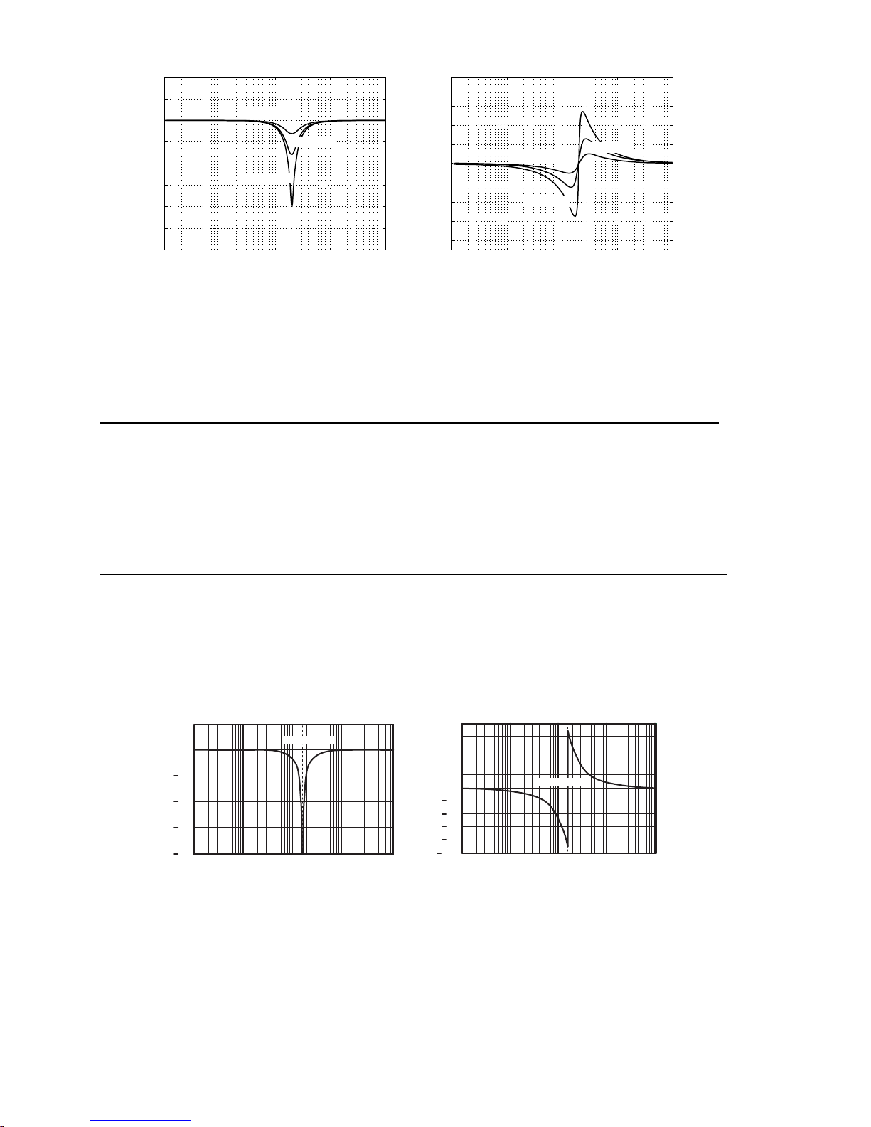
10
5
0
5
10
15
Magnitude, dB
20
25
30
0
10
10
DNOTAD.3
1
These filters operate in all
(
DMODE15
).
DNOTAD.9
2
10
Frequency, Hz
DMODE
DNOTAD.6
3
10
4
10
settings, except Autorun (
80
60
40
20
0
-20
Phase shift, degrees
-40
-60
-80
0
10
DMODE13
) and Torque/Force Tuning mode
1
10
DNOTAD.3
DNOTAD.9
Frequency, Hz
10
2
DNOTAD.6
10
3
4
10
Working with servo gains.
• Servo tuning process: refer to the Hardware Installation Guide.
• Check the values of all active gains (
• Creating and invoking gain sets: see
DNOTAF
Notch Filter A Frequency
DNOTAD
SGSET, SGENB, TGAIN, TSGSET.
is one of many servo gains): use
Type Tuning
Syntax <a_><!>DNOTAF<i>
Units i = Hz
Range 0 (disable), or 60-1000
Default 0 (filter is disabled)
Response DNOTAF: *DNOTAF200
See Also DNOTAD, DNOTAQ, DNOTBD, DNOTBF, DNOTBQ, DNOTLD, DNOTLG, TASX,
TCS, TGAIN, TSGSET
The
DNOTAF
command sets the center frequency for the commanded torque/force notch filter A. Setting
TGAIN.
Product Rev
GT6K n/a
GV6K 6.0
(applicable only to
servo axes)
this to 0 disables the filter. If setting a value results in an internal calculation error, the last valid value is
used,
bit #28 is set, and a value of 551 is written to the
TASX
TCS
register.
There are two cascaded notch filters labeled “A” and “B”. Both filters operate in exactly the same way. The
graphs below illustrate the transfer function (magnitude and phase) of the input commanded torque/force
vs. the output commanded torque/force. In this example, the notch frequency is set to 150 Hz (
and the “Q” is set to 1 (
10
0
10
20
Filter Response, dB
30
40
1 10 100 10
DNOTAQ1
These filters operate in all
(
DMODE15
).
).
DNOTAF150
3
Frequency, Hz
settings, except Autorun (
DMODE
100
80
60
40
20
0
20
40
Phase shift, degrees
60
80
4
10
100
1 10 100 10
DMODE13
DNOTAF150
Frequency, Hz
) and Torque/Force Tuning mode
3
DNOTAF150
4
10
Working with servo gains.
• Servo tuning process: refer to the Hardware Installation Guide.
• Check the values of all active gains (
• Creating and invoking gain sets: see
DNOTAF
is one of many servo gains): use
SGSET, SGENB, TGAIN, TSGSET.
TGAIN.
)
94 Gemini GV6K/GT6K Command Reference
www.comoso.com
Page 97

DNOTAQ
Type Tuning
Syntax <a_><!>DNOTAQ<r>
Units r = quality factor
Range 0.5 to 2.5
Default 1
Response DNOTAQ: *DNOTAQ1.5
See Also DNOTAD, DNOTAF, DNOTBD, DNOTBF, DNOTBQ, DNOTLD, DNOTLG, TGAIN,
The
DNOTAQ
function characteristics, refer to the
TSGSET
command sets the quality factor (Q) for notch filter A. For a description of the filter’s transfer
Notch Filter A Quality Factor
DNOTAF
command description.
Working with servo gains.
• Servo tuning process: refer to the Hardware Installation Guide.
• Check the values of all active gains (
• Creating and invoking gain sets: see
DNOTBD
Type Tuning
Syntax <a_><!>DNOTBD<i>
Units n/a
Range 0.0000 - 1.0000
Default 0.0000 (depth is zero)
Response DNOTBD: *DNOTBD.5
See Also DNOTAD, DNOTAF, DNOTAQ, DNOTBF, DNOTBQ, DNOTLD, DNOTLG, TGAIN,
The
DNOTBD
TSGSET
command sets the depth for the commanded torque/force notch filter B. Refer to
Notch Filter B Depth
DNOTAQ
SGSET, SGENB, TGAIN, TSGSET.
is one of many servo gains): use
TGAIN.
complete description of the notch filter depth.
Product Rev
GT6K n/a
GV6K 6.0
(applicable only to
servo axes)
Product Rev
GT6K n/a
GV6K 6.0
(applicable only to
servo axes)
DNOTAD
for a
Working with servo gains.
• Servo tuning process: refer to the Hardware Installation Guide.
• Check the values of all active gains (
• Creating and invoking gain sets: see
DNOTBD
SGSET, SGENB, TGAIN, TSGSET.
is one of many servo gains): use
DNOTBF
Type Tuning
Syntax <a_><!>DNOTBF<i>
Units i = Hz
Range 0 (disable), or 60-1000
Default 0 (filter is disabled)
Response DNOTBF: *DNOTBF200
See Also DNOTAD, DNOTAF, DNOTAQ , DNOTBD, DNOTBQ, DNOTLD, DNOTLG,
The
DNOTBF
TGAIN, TSGSET
command sets the center frequency for notch filter B. Setting this to 0 disables the filter. For a
Notch Filter B Frequency
description of the filter’s transfer function characteristics, refer to the
DNOTAF
command description.
Working with servo gains.
• Servo tuning process: refer to the Hardware Installation Guide.
• Check the values of all active gains (
• Creating and invoking gain sets: see
DNOTBF
SGSET, SGENB, TGAIN, TSGSET.
is one of many servo gains): use
TGAIN.
Product Rev
GT6K n/a
GV6K 6.0
(applicable only to
servo axes)
TGAIN.
Command Descriptions 95
www.comoso.com
Page 98
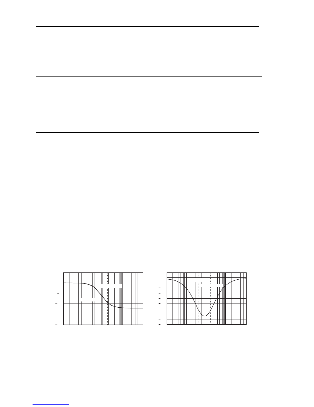
DNOTBQ
Type Tuning
Syntax <a_><!>DNOTBQ<r>
Units r = quality factor
Range 0.5 to 2.5
Default 1
Response DNOTBQ: *DNOTBQ1.5
See Also DNOTAF, DNOTAQ, DNOTBD, DNOTBF, DNOTLD, DNOTLG, TGAIN, TSGSET
The
DNOTBQ
function characteristics, refer to the
command sets the quality factor (Q) for notch filter B. For a description of the filter’s transfer
Notch Filter B Quality Factor
DNOTAF
command description.
Working with servo gains.
• Servo tuning process: refer to the Hardware Installation Guide.
• Check the values of all active gains (
• Creating and invoking gain sets: see
DNOTLD
Type Tuning
Syntax <a_><!>DNOTLD<i>
Units i = Hz
Range 0 (disable), or 80-1000
Default 0 (filter is disabled)
Response DNOTLD: *DNOTLD200
See Also DNOTAD, DNOTAF, DNOTAQ, DNOTBD, DNOTBF, DNOTLG, TASX, TGAIN,
The
DNOTLD
be used in conjunction with the
DNOTLD
TSGSET
command sets the break frequency of the lead filter. This filter cannot be used alone, but must
lead filter is configured.
Notch Lead Filter Break Frequency
DNOTLG
DNOTBQ
SGSET, SGENB, TGAIN, TSGSET.
lag filter. The
is one of many servo gains): use
DNOTLG
lag filter must be configured before the
TGAIN.
Product Rev
GT6K n/a
GV6K 6.0
(applicable only to
servo axes)
Product Rev
GT6K n/a
GV6K 6.0
(applicable only to
servo axes)
The
DNOTLD
the new
value must be less than or equal to 4 times the
DNOTLD
value will be ignored (but not overwritten), the configuration warning bit (
will be set, and the last valid
This filter operates in all
(
DMODE15
).
DMODE
DNOTLD
value will be used internally.
settings, except Autorun (
DNOTLG
DMODE13
(notch lag frequency) value; otherwise,
bit #28)
TASX
) and Torque/Force Tuning mode
In the graphs below, the transfer function is shown relating the internal commanded torqu e /force vs. the
user commanded torque/force. In this example, the lag frequency was set first to 40 Hz (
then the lead filter was set to 160 Hz (
5
0
5
10
15
Filter Response, dB
20
1 10 100 10
DNOTLG40
DNOTLD160
Frequency, Hz
DNOTLD
).
5
0
5
10
15
20
25
30
Phase shift, Degrees
35
40
3
4
10
45
1 10 100 10
DNOTLG40
DNOTLD160
Frequency, Hz
DNOTLG40
) and
3
10
Working with servo gains.
• Servo tuning process: refer to the Hardware Installation Guide.
• Check the values of all active gains (
• Creating and invoking gain sets: see
DNOTLD
is one of many servo gains): use
SGSET, SGENB, TGAIN, TSGSET.
TGAIN.
4
96 Gemini GV6K/GT6K Command Reference
www.comoso.com
Page 99

DNOTLG
Type Tuning
Syntax <a_><!>DNOTLG<i>
Units i = Hz
Range 0 (disable), or 20-1000
Default 0 (filter is disabled)
Response DNOTLG: *DNOTLG400
See Also DNOTAD, DNOTAF, DNOTAQ, DNOTBD, DNOTBF, DNOTBQ, DNOTLD, TGAIN,
The
DNOTLG
conjunction with lead filter (
value (
DNOTLD
If
DNOTLG
overwritten), the configuration warning bit (
TSGSET
command sets the break frequency of the lag filter. This filter can be used alone, or in
DNOTLG
value.
is lower than ¼ the value of
Notch Lag Filter Break Frequency
DNOTLD
) to improve the phase response of the notch filters. In this case, the lag
) must be greater than or equal to ¼ of the lead value (
DNOTLD
, the new
bit #28) will be set, and the last valid
TASX
DNOTLG
DNOTLD
), but not greater than the
value will be ignored (but not
be used internally.
This filter operates in all
(
DMODE15
).
settings, except Autorun (
DMODE
DMODE13
) and Torque/Force Tuning mode
Working with servo gains.
• Servo tuning process: refer to the Hardware Installation Guide.
• Check the values of all active gains (
• Creating and invoking gain sets: see
DNOTLG
SGSET, SGENB, TGAIN, TSGSET.
is one of many servo gains): use
TGAIN.
Product Rev
GT6K n/a
GV6K 6.0
(applicable only to
servo axes)
DNOTLG
value will
DPASS
Type Display (RP240) Interface
Syntax <a_><!>DPASS<i>
Units i = integer of up to 4 characters
Range 1 – 9999
Default For the Gx6K: DPASS6000
Response DPASS: * DPASS6000
See Also DCLEAR, DLED, DPCUR, DSTP, DVAR, DVARB, DVARI, DWRITE
The
command changes the RP240 password. If the default password is not changed by the user,
DPASS
Change RP240 Password
Product Rev
GT6K 6.0
GV6K 6.0
then there will be no password protection.
Example:
DPASS1234 ; New password = 1234
DPBW
Type Tuning
Syntax <a_><!>DPBW<r>
Units r = Hz
Range 1.00 to 100.00 : ±0.01
Default 5.00
Response DPBW: *DPBW10.00
See Also DIBW, DMTR, SGPRAT, LJRAT, TGAIN, TSGSET
AUTO-SETUP:
configuration utility in Motion Planner (see page 6). If you did not use the configuration utility or are not using a
Parker Motor, this command is set to zero and you will have to manually set this parameter. Refer to DMTR for
a list of auto-configured commands.
Position Loop Bandwidth
This command is automatically set according to the Parker motor selected with the
Product Rev
GT6K n/a
GV6K 6.0
(applicable only to
servo axes)
Command Descriptions 97
www.comoso.com
Page 100
The
command sets the bandwidth of the position loop. Higher values will increase responsiveness
DPBW
and dynamic stiffness. Excessive position loop bandwidth can result in reduced stability, causing long
settling times; this is particularly true in applications with resonant mechanics.
Working with servo gains.
• Servo tuning process: refer to the Hardware Installation Guide.
is one of many servo gains): use
• Check the values of all active gains (
• Creating and invoking gain sets: see
DPCUR
Type Display (RP240) Interface
Syntax <a_><!>DPCURi,i
Units 1st i = line number, 2nd i = column
Range line number = 1 or 2; column = 0 - 39
Default n/a
Response n/a
See Also DCLEAR, DLED, DPASS, DREADI, DSTP, DVAR, DVARI, DVARB, DWRITE
The
command changes the location of the cursor on the RP240 disp l a y . The RP240 lines are
DPCUR
Position Cursor
DPBW
SGSET, SGENB, TGAIN, TSGSET.
TGAIN.
Product Rev
GT6K 6.0
GV6K 6.0
numbered from top to bottom, 1 to 2. The columns are numbered left to right, 0 to 39.
1234567891011121314151617181920212223242526272829303132333435363738390
1234567891011121314151617181920212223242526272829303132333435363738390
F2 F3 F4 F5 F6F1
Example:
DPCUR2,15 ; Position cursor on line 2, column 15
DPHBAL
Type Drive Configuration
Syntax <a_><!>DPHBAL<r>
Units r = percent of (peak) nominal commanded current
Range 90.0 to 110.0 : ±0.1
Default 100.0
Response DPHBAL: *DPHBAL100.0
See Also DPHOFA, DPHOFB, DWAVEF
The
DPHBAL
command adjusts the current amplitude of phase B with respect to phase A.
Phase Balance
A procedure for configuring Phase Balance is provided in the Configuration chapter of the Hardware
Installation Guide.
Example:
DPHBAL110 ; sets the current amplitude of phase B to 110%
; of the current in phase A.
Product Rev
GT6K 6.0
GV6K n/a
(applicable only to
stepper axes)
98 Gemini GV6K/GT6K Command Reference
www.comoso.com
 Loading...