

Parker Automation Gemini GV6K, Gemini GT6K Command Reference Manual

p/n 88-019933-01 A
G
e
m
A
utomation
ini
G
e
m
ini
C
o
mmand
Effective: October 1, 2001
GV6K
GT6K
R
eference
a
nd
F
N
I
R
I
D
T
GF
R
T
W
AR
ST
SF
A
T
H
RR
E
GOW
NC
IT
A
O
O
H
LI
N
TP
M
R
E
O
R
N
U
M
E
E
TF
NC
F
TPE
RA
E
AD
TST
TI
NC
D
EF
D
SE
NCCN
M
T
A
TFSF
N
LS
A
L
EL
D
T
A
TIO
C
H
PS
ND
E
OY
J
FOL
KA
TS
H
O
W
ESET
R
J
FOLE
S
A
M
GTE
R
ST
C
X
ELP
N
I
N
E
H
GO
OG
N
DD
M
N
BU
V
TO
R
I
GO
P
AR
V
U
DR
T
U
O
M
O
C
F
RUN
P
S
AR
T
ES
TSSF
DA
ILE
H
W
IF
P
ELSE
SF
ARB
V
M
FE
DR
ES
R
E
TSIZ
B
C
N
SOFFS
V
EV
R
T
S
www.comoso.com
GOTO
K
TI
N
OF
U
Gem6K Series products and the information in this user guide are the proprietary property of Parker Hannifin Corporation or its licensers, and
may not be copied, disclosed, or used for any purpose not expressly authorized by the owner thereof.
Since Parker Hannifin constantly strives to improve all of its products, we reserve the right to change this user guide and software and
hardware mentioned therein at any time without notice.
In no event will the provider of the equipment be liable for any incidental, consequential, or special damages of any kind or nature
whatsoever, including but not limited to lost profits arising from or in any way connected with the use of the equipment or this user guide.
©
2001
, P
arke
All
R
ights
se
Gem6K Series products are used to control electrical and mechanical
components of motion control systems. You should test your motion
system for safety under all potential conditions. Failure to do so can result
in damage to equipment and/or serious injury to personnel.
r
H
a
nnifin
R
eserve
d
r
I
!!
C
orporation
nform
W
ARNIN
G
ation
Motion Planner and Servo Tuner are trademarks of Parker Hannifin Corporation.
Microsoft and MS-DOS are registered trademarks, and Windows, Visual Basic, and Visual C++ are trademarks of Microsoft Corporation.
T
ec
hnical
N
ort
h
Compumotor Division of Parker Hannifin
5500 Business Park Drive
Rohnert Park, CA 94928
Telephone: (800) 358-9070 or (707) 584-7558
Fax: (707) 584-3793
FaxBack: (800) 936-6939 or (707) 586-8586
e-mail: tech_help@cmotor.com
Internet: http://www.compumotor.com
A
utomation
A
merica a
A
ssistance
nd
A
sia
:
Contact your local automation technology center (ATC) or distributor,
E
urop
e
Parker Digiplan
(non-German speaking)
21 Balena Close
Poole, Dorset
England BH17 7DX
Telephone: +44 (0)1202 69 9000
Fax: +44 (0)1202 69 5750
E
-
mail
:
G
erman
y
,
HAUSER Elektronik GmbH
Postfach: 77607-1720
Robert-Bosch-Str. 22
D-77656 Offenburg
Telephone: +49 (0)781 509-0
Fax: +49 (0)781 509-176
T
ech nical
:
T
ech
A
S
_
H
elp@cmotor.com
ustri
upport
a
, S
o
witzerla
r
nd
...
:
www.comoso.com
Introduction
Purpose of this Document
This document is a reference for all the Gem6K Series commands. To gain a full understanding of how the
Gem6K Series commands are used together to implement specific features, refer to the Gem6K Series
Programmer’s Guide (p/n 88-019934-01). For hardware-related information (e.g., electrical wiring
connections, specifications, tuning, etc.), refer to the Gem6K Series Hardware Installation Guide
019932-01). Information on the Gem6K communicatio ns server (COM6SRVR) is provided in the
Communications Server Programmer’s Reference.
(p/n 88-
NOTE
The contents of this document are
available from the Motion Planner
help system. To access the help
system, use the Info window
(right), or press the F1 key.
This document is also
available in Adobe Acrobat PDF
format from our web site:
http://www.compumotor.com
Table of Contents
Page 1 Introduction:
Command Description Format
Syntax -- Letters and Symbols
Syntax -- General Guidelines
Syntax -- Command Value Substitutions
Programmable I/O Bit Patterns
Programming Error Messages
S-Curve Accel/Decel Profiling
Units of Measure and Scaling
Page 23 Special Programming Characters: Operator symbols for multi-tasking, math and bitwise
operations, relational expressions, bit select operations, etc.
Page 39 Command Descriptions: Operator symbols are described first, followed by the rest of the
Gem6K Series commands in alphabetical order.
Page 343 Appendix A: Gem6K Series Command List: Alphabetical list of all Gem6K Series commands.
Page 349 Appendix B: ASCII Character Table
Page 351 Index
Introduction
www.comoso.com
1

Description of Format
1. 2. 3.
INEN
4. Type Inputs or Program Debug Tools
5. Syntax <!><B>INEN<d><d><d>...<d>
6. Units d = 0, 1, E, or X
7. Range 0 = off, 1 = on, E = enable, X = don't care
8. Default E
9. Response INEN: *INENEEEE_EEEE_EEEE_EEEE_EEEE_EEEE_EEEE
10. See Also [IN], INFNC, INLVL, INPLC, INSTW, TIN, TIO
Item Number Description
1. Mnemonic Code: This field contains the command's mnemonic code. If the command is
2. Full Name: This field contains the command's full name.
3. Valid Product & Revision: This field lists the Gem6K Series products and the revision of
You can use the TREV command to determine which product revision you are using. For
4. Type: This field contains the command’s type.
5. Syntax: The proper syntax for the command is shown here. The specific parameters
Input Enable
in brackets (e.g., [
command (e.g., IN may be used in a conditional expression like IF(IN.3=b1)).
each product when this command was incorporated or modified per the description. If the
command does not apply to that particular product, the Rev is specified as “n/a”.
example, if the TREV response is *TREV92-016740-01-6.0, the product revision is 6.0.
associated with the command are also shown. Definitions of the parameters are described
in the Syntax sections below.
Product Rev
GT6K 6.0
GV6K 6.0
IN
]), it is an operator that must be used within the syntax of another
6. Units: This field describes what unit of measurement the parameter (b, d, i, r, or t) in the
command syntax represents.
7. Range: This is the range of valid values that you can specify for an argument (or any
other parameter specified).
8. Default: The default setting for the command is shown in this field. A command will
perform its function with the default setting if you do not provide a value.
9. Response: Some commands allow you to check the status of the command. In the
example above, entering the INEN command by itself, you will receive the response
*INENEEEE_EEEE_EEEE_EEEE_EEEE_EEEE_EEEE (response indicates all inputs are
enabled). The example responses provided are based on the default error level, Error
Level 4, established with the ERRLVL4 command.
10. See Also: Commands related or similar to the command described are listed here.
2 Gemini GV6K/GT6K Command Reference
www.comoso.com

t
Syntax – Letters and Symbols
The command descriptions provided within this manual use alphabetic letters and ASCII symbols within
the
description (see example below) to represent different parameter requirements.
Syntax
INEN
Type Inputs or Program Debug Tools
→ Syntax <!><%><B>INEN<d><d><d>...<d>
Units d = 0, 1, E, or X
Range 0 = off, 1 = on, E = enable, X = don't care
Default E
Response INEN: *INENEEEE_EEEE_EEEE_EEEE_EEEE_EEEE_EEEE
See Also [IN], INFNC, INLVL, INPLC, INSTW, TIN, TIO
Letter/Symbol Description
a_ ........Represents an address specifier, numeric value from 0 to 99. An address specifier is required if
B ...........Represents the number of the product's I/O brick. External I/O bricks are represented by numbers 1
b *.........Represents the values 1, 0, X or x; does not require field separator between values.
c ...........Represents a character (A to Z, or a to z)
d ...........Represents the values 1, 0, X or x, E or e ; does not require field separator between values. E or e
i ...........Represents a numeric value that cannot contain a decimal point (integer values only). The numeric
r ...........Represents a numeric value that may contain a decimal point, but is not required to have a decimal
t ...........Represents a string of alpha numeric characters from 1 to 6 characters in length. The string must
! ...........Represents an immediate command. Changes a buffered command to an immediate command.
% ...........(Multitasking Only) Represents a task identifier. To address the command to a specific task, prefix the
, ...........Represents a field separator. Commands with the symbol r or i in their Syntax description require
@ ...........Represents a global specifier, where only one field need be entered. Applicable to all commands with
< > ......Indicates that the item contained within the < > is optional, not required by that command.
[ ] ......Indicates that the command between the [ ] must be used in conjunction with another command,
* The ASCII character b can also be used within a command to precede a binary number. When the b is used in this
context, it is not to be replaced with a 0, 1, X, or x. Examples are assignments such as VARB1=b10001, and
comparisons such as IF(3IN=b1001X1).
Input Enable
Product Rev
GT6K 6.0
GV6K 6.0
multiple Gem6K drives are connected in a daisy-chain or multi-drop configuration; in fact, leaving off
the address specifier will cause parameter assignment commands to affect all units and
response/transfer commands to request information from all units at the same time (multiple units
transmitting characters at one time will garble the communication). To assign unique unit addresses
to multiple drives, refer to the ADDR command.
through n (to connect external I/O bricks, refer to the Installation Guide). On-board I/O are address at
brick location zero (Ø). If the brick identifier is omitted from the command, the controller assumes the
command is supposed to affect the onboard I/O.
enables a specific command field. X or x leaves the specific command field unchanged or ignored. In
the ANIEN command, the “d” symbol may also represent a real numeric value.
range varies by command. Field separator required.
point. The numeric range varies by command. Field separator required.
start with a alpha character.
Immediate commands are processed immediately, even before previously entered buffered
commands.
command with “i%”, where “i” is the task number. For example, the 4%CUT command uses task #4 to
execute the program called “CUT”.
field separators. Commands with the symbol b or d in their Syntax description
separators (but they may be included). See General Guidelines table below.
multiple command fields. (e.g.,
NOTE: Do not confuse with <cr>, <sp>, and <lf>, which refer to the ASCII characters
corresponding to a carriage return, space, and line feed, respectively.
and cannot be used by itself.
@OUT1
sets output #1 on for all I/O bricks).
do not
require field
Order of Precedence for Command Prefix Characters (from left to right):
s
1
: Immediate
nd
2
: Task number
rd
3
: Apply to all I/O bricks, etc.
rd
3
: Address number
rd
3
: I/O brick number
Introduction
<!><%><@><a_><B>
www.comoso.com
3

Syntax – General Guidelines
Guideline Topic Guideline Examples
Command Delimiters
(<cr>, <lf>, and :)
Neutral Characters
(<sp> and <tab>)
Case Sensitivity
Comment Delimiter (;)
Field Separator (,)
All commands must be separated by a
delimiter. A carriage return is the most
commonly used. The colon (:)allows you to
place multiple commands on one line of code.
Using neutral characters anywhere within a
command will not affect the command.
There is no case sensitivity. Use upper or
lower case letters within commands.
Set acceleration to 10 rev/sec/sec:
A10<cr>
A10<lf>
A10:
V25 : D25000 : GO<cr>
Set velocity to 10 rps:
V<sp>10<cr>
Initiate motion:
GO1
go1
All text between a comment delimiter and a
command delimiter is considered program
Add a comment to the command:
V10<tab> ;set velocity
comments.
Commands with the symbol r or i in their
Syntax description require field separators.
Display variable #1 on the RP240 at the current
cursor location with 3 characters displayed to
the left of the decimal, 2 to the right of the
decimal, and the sign:
DVAR1,3,2,1
Commands with the symbol b or d in their
Syntax description
do not
require field
separators (but they may be included).
Enable error checking for hard limits and drive
faults:
ERROR0101
Global Command
Identifier (@)
Bit Select Operator (.)
Left-to-right Math
Binary and Hexadecimal
Values
Multi-tasking Task
Identifier (%)
When you wish to set the command value
equal on all outputs, add the @ symbol at the
beginning of the command (enter only the
value for one command field).
The @ symbol is also useful for checking
the status of all inputs or
outputs on all I/O bricks.
The bit select operator allows you to affect
one or more binary bits without having to
enter all the preceding bits in the command.
Syntax for setup commands:
[command name].[bit #]-[binary value]
Syntax for conditional expressions:
[command name].[bit #]=[binary value]
All mathematical operations assume
left-to-right precedence.
When making assignments with or
comparisons against binary or hexadecimal
values, you must precede the binary value
with the letter “b” or “B”, and the hex value
with “h” or “H”. In the binary syntax, an “x”
simply means the status of that bit is ignored.
Use the % command prefix to identify the
command with a specific task.
Set the digital outputs (#1 & #2) active on all
digital outputs (onboard and external):
@OUT11
Check the status of all digital outputs (onboard,
and on external I/O bricks):
@OUT
Enable error-checking bit #9:
ERROR.9-1
Enable error-check bits #9-12:
ERROR.9-1,1,1,1
IF statement based on value of axis status bit
#12 for axis #1:
IF(1AS.12=b1)
VAR1=5+3*2
Result: Variable 1 is assigned the value of 16
(8*2), not 11 (5+6)
.
Binary: IF(IN=b1x01)
Hexadecimal: IF(IN=h7F)
Launch the “move1” program in Task 1:
1%move1
Check the error status for Task 3:
3%TER
Check the system status for Task 3:
3%TSS
: The command line is limited to 80 characters (excluding spaces).
NOTE
4 Gemini GV6K/GT6K Command Reference
www.comoso.com

Syntax – Command Value Substitutions
Many commands can substitute one or more of its command field values with one of these substitution
items (demonstrated in the programming example below):
VAR............. Places current value of the numeric variable in the corresponding field of the command.
VARB........... Uses the value of the binary variable to establish all
VARI........... Places current value of the integer variable in the corresponding field of the command.
READ........... Information is requested at the time the command is executed.
DREAD ........ Reads the RP240’s numeric keypad into the corresponding field of the command.
DREADF...... Reads the RP240’s function keypad into the corresponding field of the command.
TW ............... Places the current value set on the thumbwheels in the corresponding field of the command.
DAT............. Places the current value of the data program (DATP) in the corresponding field of the command.
(NOTE: The substitution item must be enclosed in parentheses.)
Programming Example:
VAR1=15 ; Set variable 1 to 15
A(VAR1) ; Set acceleration to 15
VARB1=b101XX ; Set binary variable 1 to 101XX (bits 4 & 5 not affected)
OUT(VARB1) ; Turn on ouputs 1 & 3, turn off output 2, don’t change outputs 4 &
VARS1="Enter Velocity" ; Set string variable 1 to the message "Enter Velocity"
V(READ1) ; Read in the velocity, output variable string 1 as the prompting
; 1. Operator sees "ENTER VELOCITY" displayed on the screen.
; 2. Operator enters velocity prefixed by !' (e.g., !'20).
HOMV(TW1) ; Read in the home velocity from thumbwheel set 1
HOMVF(DAT1) ; Read home final velocity from data program 1.
VARI1=2*3 ; Set integer variable 1 to 6 (2 multiplied by 3)
D(VARI2) ; Set the distance equal to the value of
; integer variable 2.
5.
message
the fields in the command.
Rule of Thumb
Not all of the commands allow command field substitutions. In
general, commands with a binary command field (
syntax) will accept the
or integer command field (
VAR, VARI, READ, DREAD, DREADF, TW
VARB
substitution. Commands with a real
<r>
or
<i>
in the syntax) will accept
DAT
or
<b>
in the
.
Introduction
www.comoso.com
5

Programming Interface Tools
Motion Planner, a graphical programming interface, is provided as a tool for programming your Gem6K
drive. These are the functions provided:
• Configuration (motor selection, tuning, motor matching and damping, etc.)
• Terminal emulation for sending commands and checking drive status
• Program editor for developing program files to send to the drive
• Downloading and uploading program and operating system files to/from the drive
Motion Planner runs on the Windows 95, Windows 98 an d Windows NT operating systems.
Motion Planner is installed from the “Motion Planner” CD which is included in your Gem6k drive
shipment (unless you ordered the -NK option).
Communications Server: Also available on the Motion Planner CD is the Communications Server
(COM6SRVR.EXE). COM6SRVR.EXE is a 32-bit OLE automation server that allows you to add Gem6K
(as well as Gemini and 6K) communication capability to your cu stom applications created with
programming languages such as Visual Basic, Visual C++, and Delphi. The Motion Planner installation
program installs
COM6SRVR.EXE
functions are provided in the COM6SRVR Communications Server User Guide.
in the Motion Planner directory. Details on the Communication Server
NOTE
The Gem6K commands described in this document can be used only with Motion
Planner or the COM6SRVR Communications Server.
Using Motion Planner with a Gem6K Drive
Motion Planner is a programming interface for the Gemini product family, as well as the 6K product
family. Motion Planner runs on the Windows 95, Windows 98 and Windows NT operating systems.
Below are instructions on how to use Motion Planner with your Gem6K.
Installing Motion Planner:
System Requirements:
• IBM-compatible PC with a Pentium 166 MHz or higher processor.
• Operating system: Microsoft Windows 95, Microsoft Windows NT Workstation 4.0, or
Microsoft Windows 98.
• 32MB RAM.
• Hard disk space: 16MB minimum.
• PCI VGA with 800 x 600 resolution or higher.
• CD-ROM drive or internet access for installation.
• Mouse or pointing device.
• RS-232C serial port for using serial RS-232C communications.
Insert the Motion Planner CD in your CD-ROM player. The installation program
automatically launches and displays this dialog:
6 Gemini GV6K/GT6K Command Reference
www.comoso.com

Updating the Drive’s Operating System:
Gem6K drives are digital motor drives that run under an internal software operating system. The
operating system was loaded into your drive during the manufacturing process, and under
ordinary circumstances you will not need to update your drive’s operating system. However,
because Compumotor continues to add enhancements and address software bugs, you may want
to upgrade the operating system. You may obtain a new operating system file from the
Compumotor web site, or from Technical Support (see phone numbers on the inside cover of this
manual).
Web Site Download:
The operating system file is located in the software download section of the Compumotor
Online web site (
For example, the operating system file for version 1.50 is called GEM_1_50.ops. Download
the file to the Motion Planner directory on your hard drive.
Update Procedure:
1. Using the Gem6K’s RS-232 connector (COM 2), connect to your computer’s RS-232
serial communication port (see instructions in the Hardware Installation Guide).
NOTE: You can download the operating system to only one drive unit at a time and you
must use RS-232 communication (no daisy chains).
NOTE: You must use the Gem6K’s RS-232 connector (COM 2), not the RS-232/485
connector (COM 1).
2. Launch Motion Planner.
3. In the Default Communications Settings dialog box, select your Gem6K drive and select
the serial port to which the drive is connected, then click “OK”.
4. Click on the Terminal tab to expose the terminal emulator.
5. From the
the
Locate Gem6K Operating System
button. This initiates the download to the drive and displays th e download status
Open
dialog.
6. When the download is completed successfully, Motion Planner displays a confirmation
message. Also, the drive automatically resets itself and displays the
the terminal emulator window. Check the
system revision is now in the drive (e.g., the response “
indicates that the drive is using OS revision 1.05, denoted by “
http://www.compumotor.com
Communications
). The file name is in this format: GEM_n_nn.ops.
pull-down menu, select
dialog, locate the operating system file and click the
report to verify that the proper operating
TREV
Download OS
*TREV-GV-L3E_D1.05_F1.00
. When presented with
response in
TREV
”).
D1.05
”
NOTE: If the download is interrupted or corrupted, the drive will
flash the left LED (red) until a valid operating system is downloaded.
Introduction
7
www.comoso.com
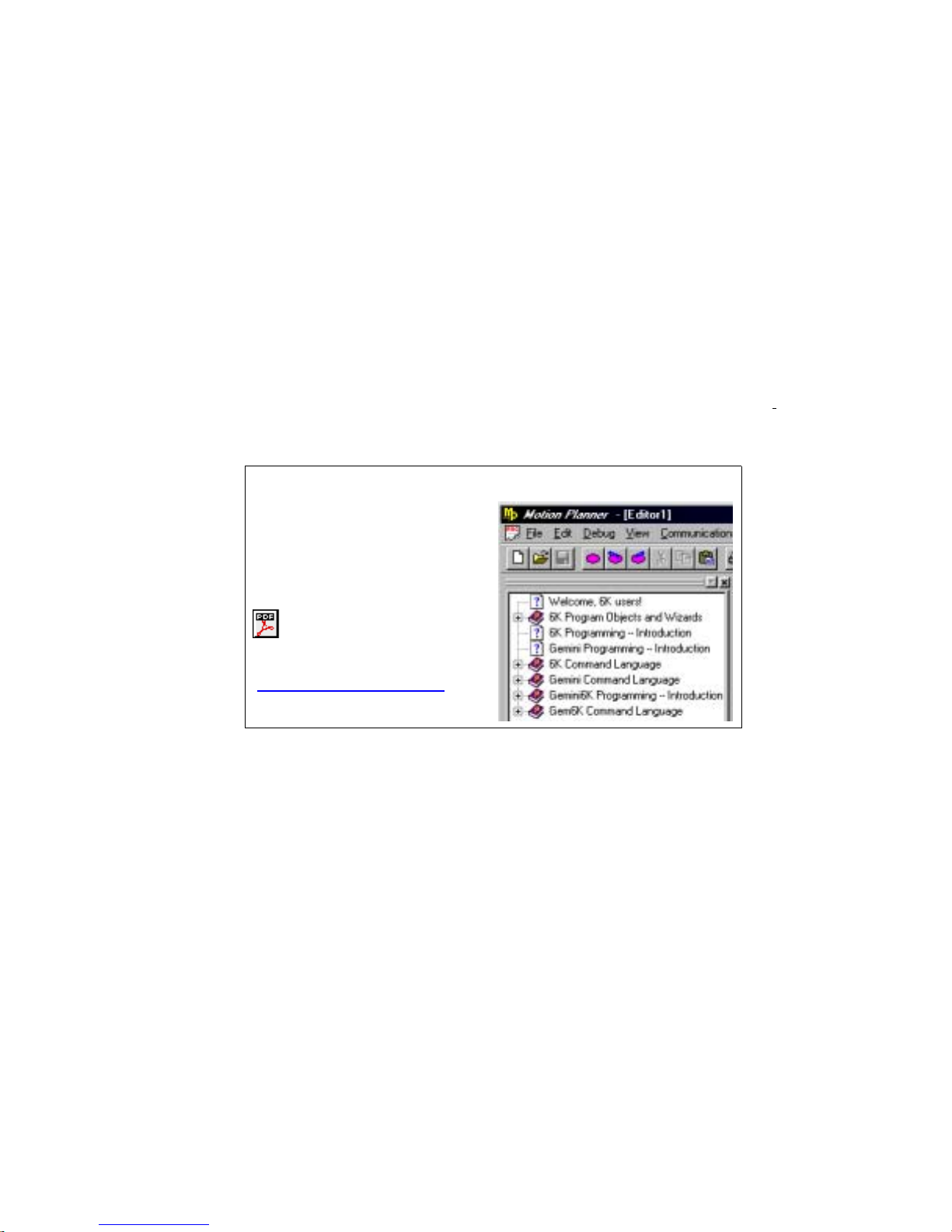
Programmable I/O Bit Patterns
The Gem6K has programmable inputs and outputs. The total number of onboard inputs and outputs (analog
inputs, digital inputs and digital outputs) is fixed. The total number of expansion inputs and outputs depends on
your configuration of expansion I/O bricks.
These programmable I/O are represented by binary bit patterns, and it is the bit pattern that you reference when
programming and checking the status of specific inputs and outputs. The bit pattern is referenced 1 to n, from
left to right.
• Onboard I/O
An example response is:
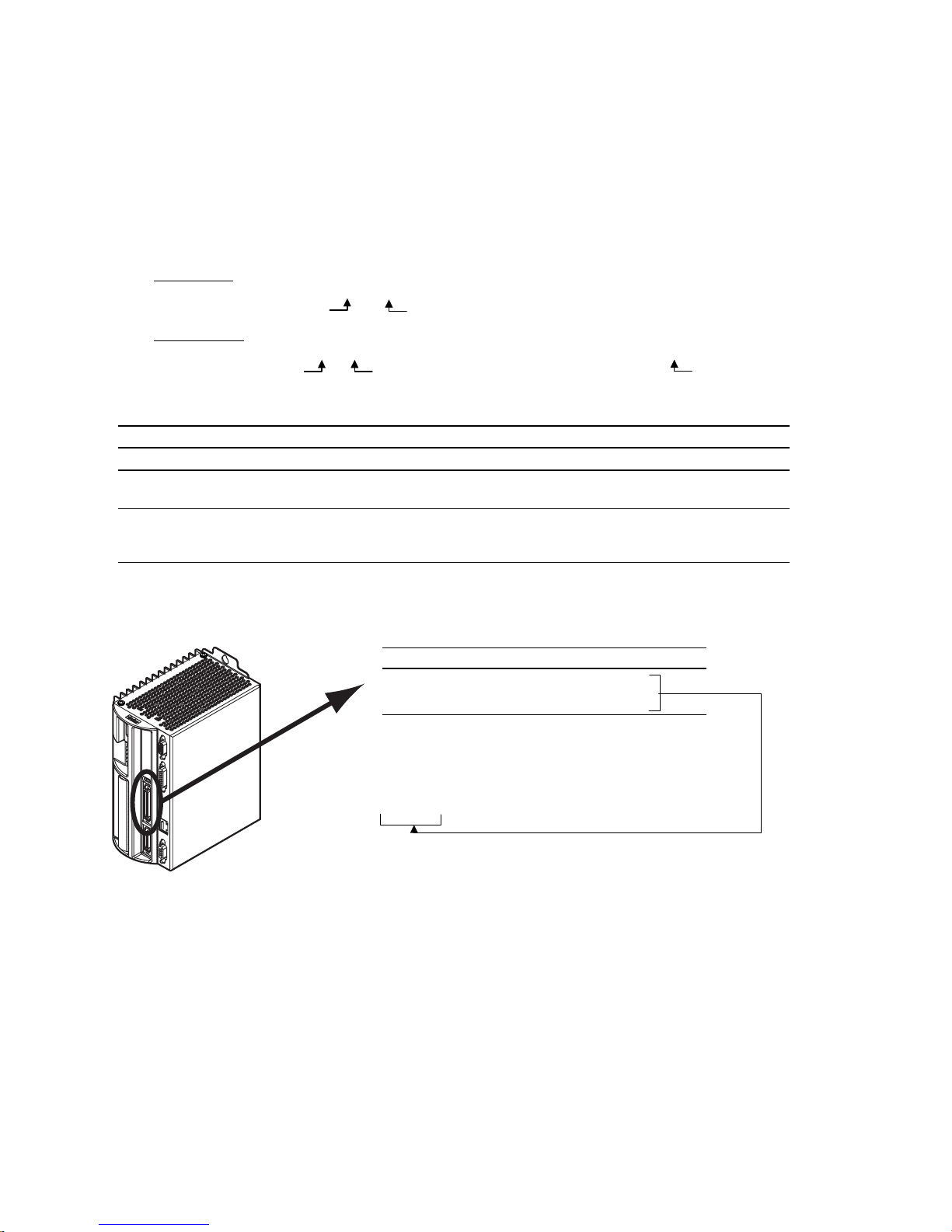
• Expansion I/O
An example response is:
Onboard I/O
I/O Location Programming Status Report, Assignment
Limit Inputs “
Inputs (digital) “DRIVE I/O” connector
Outputs (digital) “DRIVE I/O” connector
. For example, the status command to check all onboard inputs is
*TIN0100_0
Bit 1
.
Bit 5
TIN
.
. For example, the status command to check all digital inputs on I/O brick 2 is
*2TIN0010_0110_1100_0000_XXXX_XXXX_XXXX_XXXX
I/O Brick 2
Bit 1
DRIVE I/O
” connector
LIMFNC, LIMEN, LIMLVL TLIM, LIM
INFNC, INLVL, INEN, ONIN,
INPLC, INSTW
OUT, OUTFNC, OUTLVL,
OUTEN, OUTALL, OUTPLC,
OUTTW, POUT
TIN, IN
TOUT, [OUT]
.
Bit 32
2TIN
.
Limit Inputs
(“DRIVE I/O” connector)
Input bit pattern for
Bit # Pin # Function
1 28 Positive end-of-travel limit
2 29 Negative end-of-travel limit
3 31 Home limit
* The functions listed are the factory default functions; other
functions may be assigned with the
Sample response to
*TLIM110
LIM, TLIM, LIMEN, LIMFNC
*
(limit inputs status) command:
TLIM
LIMFNC
, and
LIMLVL:
command.
8 Gemini GV6K/GT6K Command Reference
www.comoso.com
(“DRIVE I/O” connector)
Inputs
Outputs
(“DRIVE I/O” connector)
Input bit pattern for
INEN, INPLC, INSTW
Bit # Pin # Function
1 37 Input 1 (if assigned, TRIG-A)
2 38 Input 2 (if assigned, TRIG-B)
3 39 Input 3
4 34 Input 4
5 35 Input 5 (if assigned, TRIG-M)
* If the input is assigned the “trigger
interrupt” function with the
command:
TRIG-A must be on Input 1
TRIG-B must be on Input 2
TRIG-M must be on input 5
Sample response to
*TIN0010_1
TIN, IN, INFNC, INLVL
, and
ONIN:
*
INFNCi-H
(input status) command:
TIN
,
Output bit pattern for
OUTLVL, OUTEN, OUTALL, OUTPLC, OUTTW, POUT:
Bit # Pin # Function
1 41 Output 1.
2 43 Output 2.
3 45 Output 3.
4 46 Output 4.
5 48 Output 5.
6 49 Output 6.
7 Relay Output 7.
TOUT, [OUT], OUT, OUTFNC
,
Sample response to
(onboard outputs status) command:
*TOUT0000_000
TOUT
Introduction
www.comoso.com
9
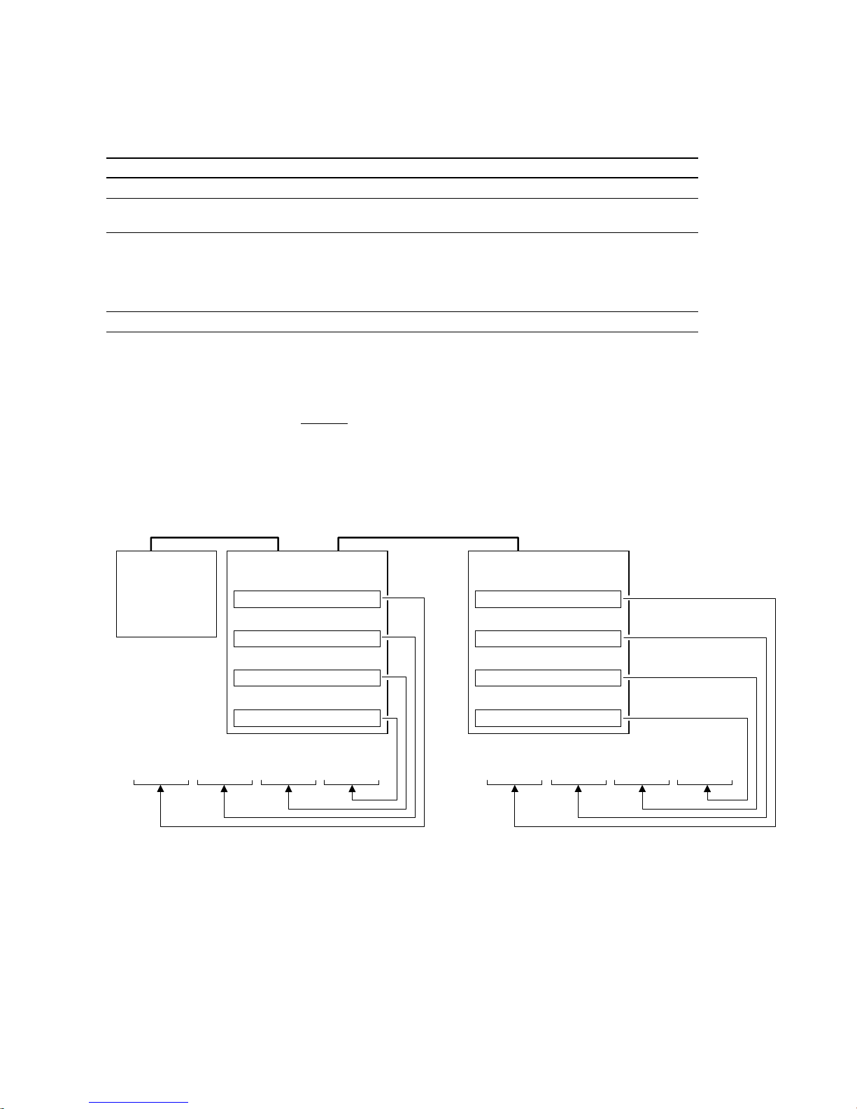
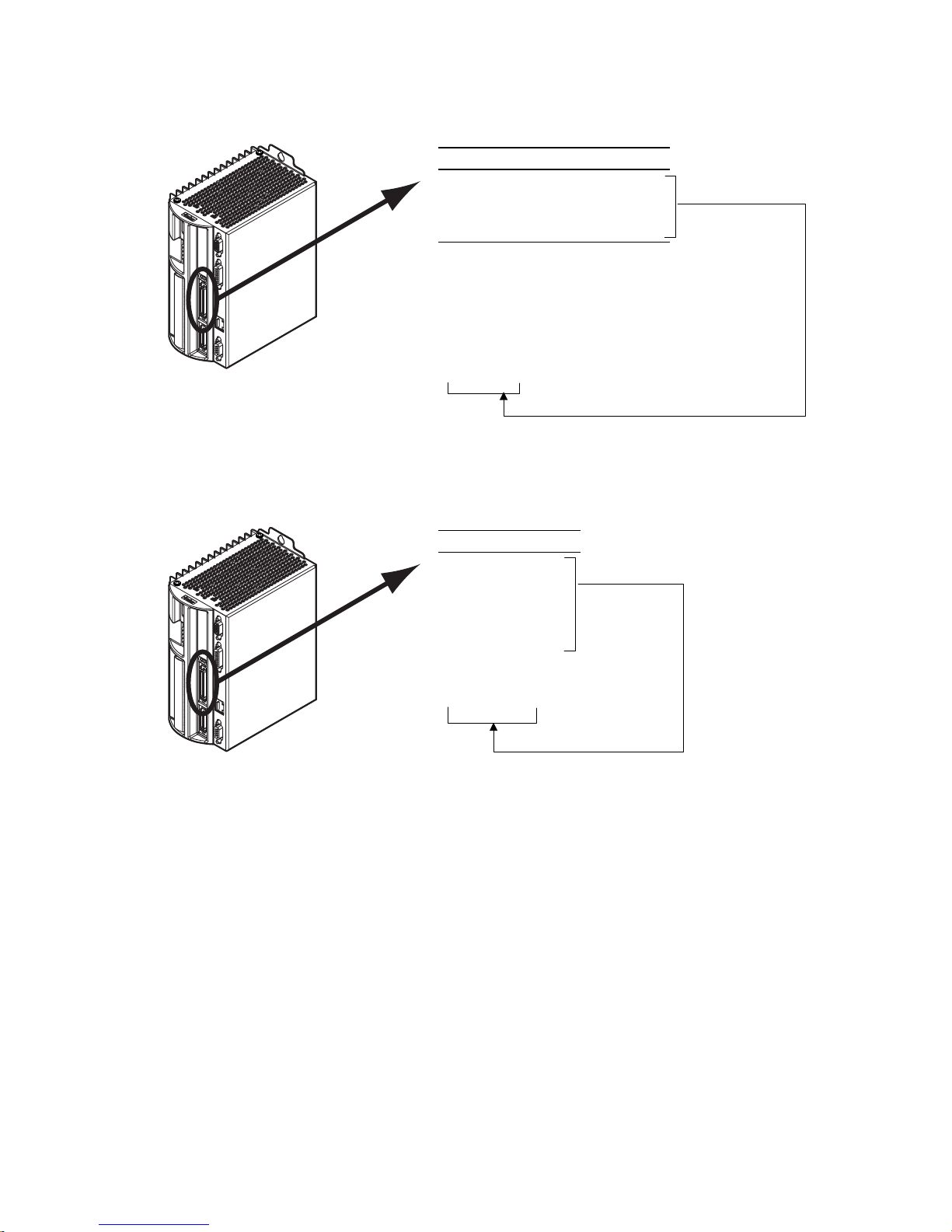
Expansion I/O Bricks
The Gem6K allows you to expand your system I/O by connecting up to eight I/O bricks (see Installation
Guide for connections). Expansion I/O bricks may be ordered separately (referred to as the “EVM32”). Each
I/O brick can hold from 1 to 4 of these I/O SIM modules in any combination:
SIM Type Programming Status Report, Assignment
Digital Inputs SIM (8 inputs)
Digital Outputs SIM (8 outputs)
Analog Inputs SIM (8 inputs)
Analog Outputs SIM (8 outputs)
Each I/O brick has a unique “brick address”, denoted with the “
I/O bricks are connected in series to the “
address #1, the next brick has address #2, and so on. (NOTE: If you leave out the brick address in the
command, the Gem6K will assume you are addressing the command to the onboard I/O.) Each I/O brick
has 32 I/O addresses, referenced as absolute
• SIM slot 1 = I/O points 1-8
• SIM slot 2 = I/O points 9-16
• SIM slot 3 = I/O points 17-24
• SIM slot 4 = I/O points 25-32
INFNC, INLVL, INEN, ONIN, INPLC, INSTW TIN, IN, TIO
OUT, OUTFNC, OUTLVL, OUTEN, OUTALL,
OUTPLC, OUTTW, POUT
• Enable/Disable: ANIEN.
• Voltage range: ANIRNG.
• Joystick setup: JOYAXH, JOYCDB,
JOYCTR, JOYEDB, JOYZ.
• Following master source: ANIMAS, FOLMAS
ANO
” symbol in the command syntax. The
<B>
EXPANSION I/O
” connector on the Gem6K. The 1st I/O brick has
TOUT, [OUT], TIO
• Voltage: TANI, ANI, TIO
TANO, [ANO], TIO
I/O point locations:
Example:
Gem6K
Drive/Controller
Sample response to
*1TIN0000_0010_1100_0000_0100_0001_XXXX_XXXX
command identifies the connected I/O bricks (and installed SIMs), including the status of each I/O point:
TIO
The
*BRICK 1: SIM Type Status Function
1-8: DIGITAL INPUTS 0000_0000 AAAA_AAAA
9-16: DIGITAL INPUTS 0000_0000 AAAA_AAAA
17-24: DIGITAL INPUTS 0000_0000 AAAA_AAAA
25-32: ANALOG INPUTS 0.000,0.000,0.000,0.000,0.000,0.000,0.000,0.000
*BRICK 2: SIM Type Status Function
1-8: DIGITAL OUTPUTS 0000_0000 AAAA_AAAA -- SINKING
9-16: DIGITAL INPUTS 0000_0000 AAAA_AAAA
17-24: NO SIM PRESENT
25-32: DIGITAL OUTPUTS 0000_0000 AAAA_AAAA -- SOURCING
I/O Brick #1
Slot #1 (I/O points 1-8)
Digital Inputs SIM
Slot #2 (I/O points 9-16)
Digital Inputs SIM
Slot #3 (I/O points 17-24)
Digital Inputs SIM
Slot #4 (I/O points 25-32)
Analog Inputs SI M
(digital inputs status) command:
1TIN
I/O Brick #2
Slot #1 (I/O points 1-8)
Digital Outputs SIM
Slot #2 (I/O points 9-16)
Digital Inputs SIM
Slot #3 (I/O points 17-24)
No S IMM insta lled
Slot #4 (I/O points 25-32)
Digital Outputs SIM
Sample response to
*2TOUT0000_0000_XXXX_XXXX_XXXX_XXXX_0000_0000
(digital outputs status) command:
2TOUT
10 Gemini GV6K/GT6K Command Reference
www.comoso.com

Programming Error Messages
Depending on the error level setting (set with the
ERRLVL
command), when a programming error is created,
the Gem6K will respond with an error message and/or an error prompt. A list of all possible error messages is
provided in a table below. The default error prompt is a question mark (
ERRBAD
At error level 4 (
the error prompt. At error level 3 (
Error Response Possible Cause
ACCESS DENIED
ALREADY DEFINED FOR THUMBWHEELS
ALTERNATIVE TASK NOT ALLOWED
AXES NOT READY
COMMAND NOT IMPLEMENTED
COMMAND NOT ALLOWED IN PROGRAM
COMMAND/DRIVE MISMATCH
ERROR: MOTION ENDS IN NON-ZERO
VELOCITY
command if you wish.
ERRLVL4
—the factory default setting) the Gem6K responds with both the error message and
ERRLVL3
), the Gem6K responds with only the error prompt.
Program security feature enabled, but the program access input (INFNCi-Q or
LIMFNCi-Q) is not activated.
Attempting to assign an I/O function to an I/O that is already defined as a
thumbwheel I/O.
Attempting to execute a LOCK command directed to another task.
Compiled Profile path compilation error.
Command is not applicable to the Gem6K Series product.
Command is not allowed inside a program definition (between DEF and END).
The command is not appropriate to the type of drive being used (e.g.,
attempting to execute a servo tuning command on a stepper axis)
Compiled Motion: The last GOBUF segment within a PLOOP/PLN loop does not
end at zero velocity, or there is no final GOBUF segment
), but you can change it with the
?
placed outside the loop
.
FOLMAS NOT SPECIFIED
INCORRECT AXIS
INCORRECT BRICK NUMBER
INCORRECT DATA
INPUT(S) NOT DEFINED AS
JOYSTICK INPUT
INSUFFICIENT MEMORY
INVALID COMMAND
No FOLMAS for the axis is currently specified. It will occur if FMCNEW, FSHFC, or
FSHFD commands are executed and no FOLMASØ command was executed, or
FOLMAS0 was executed.
Axis specified is incorrect.
Attempted to execute a command that addresses an I/O brick that is not
connected to your Gem6K controller.
Incorrect command syntax.
Following: Velocity (V), acceleration (A) or deceleration (AD) command is zero
(used by FSHFC & FSHFD).
Attempted to execute JOYCDB, JOYCTR, JOYEDB, or JOYZ before executing
JOYAXH to assign the analog input.
Not enough memory for the user program or compiled profile segments. This
may be remedied by reallocating memory (see MEMORY command description).
Command is invalid because of existing conditions
Introduction
www.comoso.com
11

Programming Error Messages
Error Response Possible Cause
INVALID CONDITIONS FOR COMMAND
INVALID CONDITIONS FOR
S_CURVE ACCELERATION—FIELD n
INVALID DATA
(continued)
System not ready for command (e.g., LN command issued before the L
command).
Following (these conditions can cause an error during Following):
• The FOLMD value is too small to achieve the preset distance and still
• A phase shift cannot be performed:
• The FOLEN1 command was given while a profile was suspended by a
Average (AA) acceleration or deceleration command (e.g., AA, ADA, HOMAA,
HOMADA, etc.) with a range that violates the equation ½A ≤ AA ≤ A (A is the
max. accel or decel command—e.g., A, AD, HOMA, HOMAD, etc.)
Data for a command is out of range.
Following (these conditions can cause an error during Following):
• The parameter supplied with the command is valid.
• Error if a GO command is given in the preset positioning mode (MCØ) and:
remain within the FOLRN/FOLRD ratio.
FSHFD.... Error if already shifting or performing other time based move.
FSHFC.... Error if currently executing a FSHFD move, or if currently
GOWHEN.
FFILT Error if: smooth number is not 0-4
FMCLEN.. Error if: master steps > 999999999 or negative
FMCP ......Error if: master steps > 999999999 or < -999999999
FOLMD.... Error if: master steps > 999999999 or negative
FOLRD.... Error if: master steps > 999999999 or negative
FOLRN.... Error if: follower steps > 999999999 or neg ative
FSHFC.... Error if: number is not 0-3
FSHFD.... Error if: follower steps > 999999999 or < -999999999
GOWHEN.. Error if: position > 999999999 or < -999999999
WAIT ......Error if: position > 999999999 or < -999999999
FOLRN = zero
FOLMD = zero, or too small
(see Following chapter in the Programmer’s Guide)
executing another FSHFC move in the opposite direction.
INVALID FOLMAS SPECIFIED
INVALID RATIO
INVALID TASK IDENTIFIER
LABEL ALREADY DEFINED
MASTER SLAVE DISTANCE MISMATCH
MAXIMUM COMMAND LENGTH EXCEEDED
MAXIMUM COUNTS PER SECOND
EXCEEDED
MOTION IN PROGRESS
NEST LEVEL TOO DEEP
Following: An illegal master was specified in FOLMAS. A follower may never
use its own commanded position or feedback source as its master.
Following: Error if the FOLRN:FOLRD ratio after scaling is > 127 when a GO is
executed.
Attempting to launch a PEXE or EXE command into the supervisor task (task 0).
Defining a program or label with an existing program name or label name.
Attempting a preset Following move with a FOLMD value that is too small.
Command exceeds the maximum number of characters.
Velocity value is greater than 1,600,000 counts/sec.
Attempting to execute a command not allowed during motion (see Restricted
Commands During Motion section in the Programmer's Guide.)
Following: The FOLEN1 command was given while that follower was moving in
a non-Following mode.
IFs, REPEATs, WHILEs, or GOSUBs nested greater than 16 levels
12 Gemini GV6K/GT6K Command Reference
(for each type).
www.comoso.com

Programming Error Messages
Error Response Possible Cause
NO MOTION IN PROGRESS
NO PATH SEGMENTS DEFINED
NO PROGRAM BEING DEFINED
NOT ALLOWED IN PATH
NOT VALID DURING FOLLOWING
MOTION
NOT VALID DURING RAMP
OUTPUT USED AS OUTFNC
PROFILE ALREADY MOVING
PROFILE NOT COMPILED
(continued)
Attempting to execute a command that requires motion, but motion is not in
progress.
Compiled Profile compilation error.
END command issued before a DEF command.
Compiled Profile path compilation error.
A GO command was given while moving in the Following mode (FOLEN1) and
while in the preset positioning mode (MCØ).
A GO command was given while moving in a Following ramp and while in the
continuous positioning mode (MC1). Following status (FS) bit #3 will be set to 1.
A FOLEN command was given during one of these conditions:
• During a shift (FSHFC or FSHFD)
• During a change in ratio (FOLRN/FOLRD)
• During deceleration to a stop
Attempting to change an output that is not an OUTFNCi-A output.
Compiled Profile compilation error.
Attempting to execute a profile that has not been compiled.
STRING ALREADY DEFINED
STRING IS A COMMAND
UNDEFINED LABEL
WARNING: POINTER HAS WRAPPED
AROUND TO DATA POINT 1
WARNING: ENABLE INPUT INACTIVE
WARNING: DEFINED WITH ANOTHER
TW/PLC
A string (program name or label) with the specified name already exists.
Defining a program or label that is a command or a variant of a command.
Command issued to product is not a command or program name.
During the process of writing data (DATTCH) or recalling data (DAT), the pointer
reached the last data element in the program and automatically wrapped
around to the first datum in the program.
ENABLE
Duplicate I/O in multiple thumbwheel definitions.
input is no longer connected to ground (
GND
).
Introduction
www.comoso.com
13

Identifying Bad Commands
To facilitate program debugging, the Transfer Command Error (
TCMDER
) command allows you to transfer
the first command that the controller detects as an error. This is especially useful if you receive an error
message when running or downloading a program, because it catches and remembers the command that
caused the error.
Using Motion Planner
will detect the bad command and respond with an error message, followed by the
prompt (
automatically (see example below).
). If the bad command was detected on download, the bad command is reported
?
NOTE: If you are not using Motion Planner, you'll have to type in the TCMDER
: If you are typing the command in a live terminal emulator session, the controller
ERRBAD
error
command at the error
prompt to display the bad command.
Once a command error has occurred, the command and its fields are stored and system status bit #11
(reported in the
TSSF, TSS
and SS commands) is set to 1. The status bit remains set until the
TCMDER
command is issued.
Example Error Scenario:
1. In Motion Planner's program editor, create and save a program with a programming error:
DEL badprg ; Delete a program before defining and downloading
DEF badprg ; Begin definition of program called badprg
MA1 ; Select the absolute preset positioning mode
A25 ; Set acceleration
AD11 ; Set deceleration
V5 ; Set velocity
VAR1=0 ; Set variable #1 equal to zero
GO1 ; Initiate move
IF(VAR1<)16 ; MISTYPED IF STATEMENT - should be typed as "IF(VAR1<16)"
VAR1=VAR1+1 ; If variable #1 is less than 16, increment the counter by 1
NIF ; End IF statement
END ; End programming of program called badprg
2. Using Motion Planner's terminal emulator, download the program to the Gem6K Series product. Notice
that an error response identifies the bad command as an “
> *NO ERRORS
*INCORRECT DATA
> *IF(VAR1<)16
INCORRECT DATA
” item and displays it:
14 Gemini GV6K/GT6K Command Reference
www.comoso.com
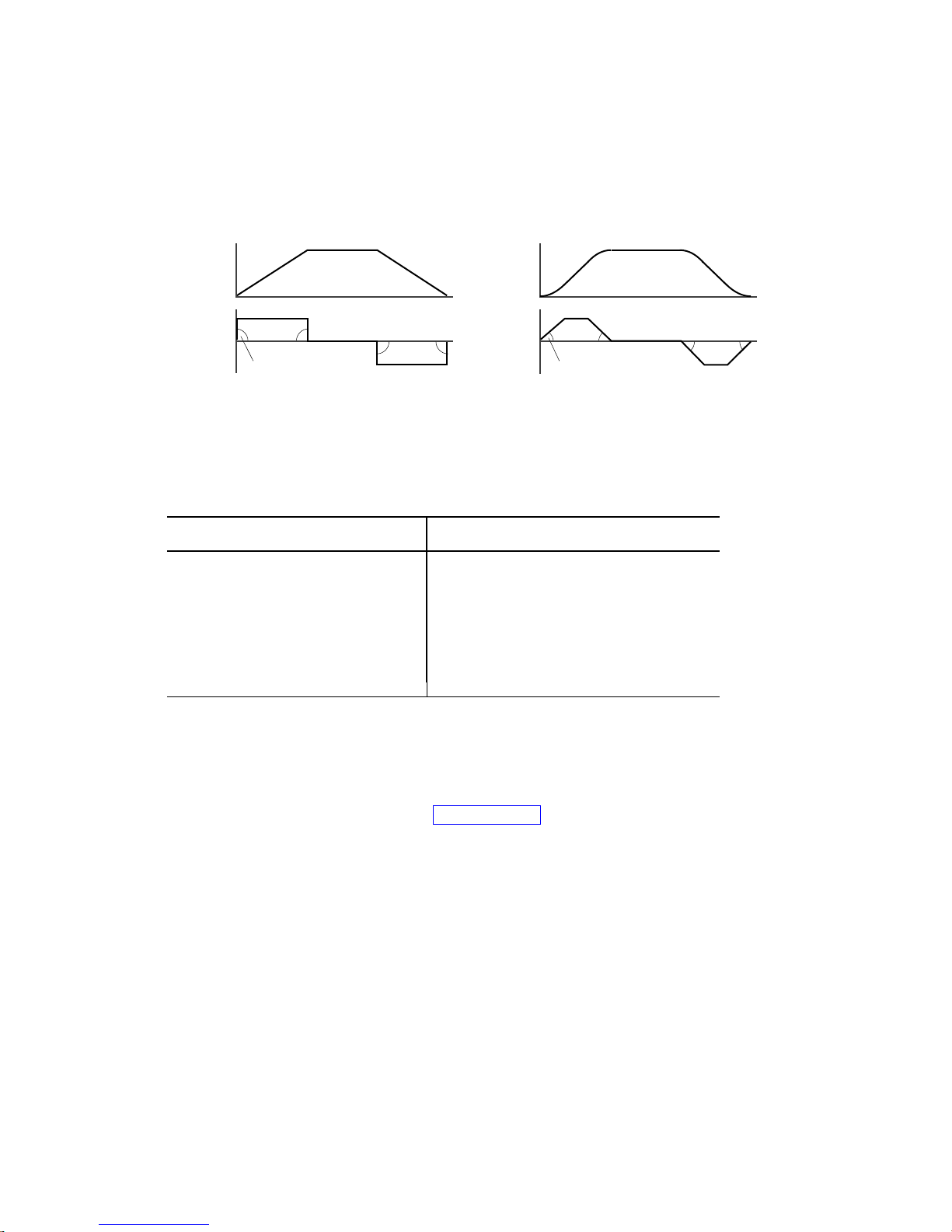
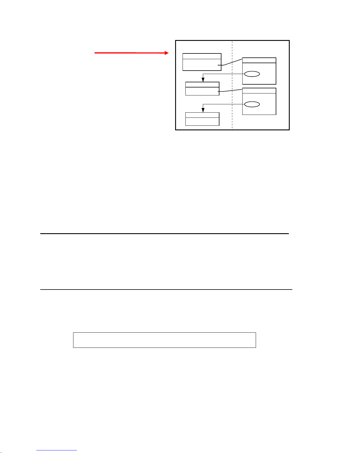
S-Curve Acceleration/Deceleration Profiling
The Gem6K allows you to perform S-curve move profiles, in addition to the usual trapezoidal profiles.
S-curve profiling provides smoother motion control by reducing the jerk (rate of change) in acceleration
and deceleration portions of the move profile (see drawing below). Because S-curve profiling reduces jerk,
it improves position tracking performance, especially in linear interpolation applications.
Accel
Maximum Jerk
Decel Velocity
Trapezoidal
Time
Time
Velocity
Decel Accel
Less Jerk
S-Curve
Time
Time
S-Curve Programming Requirements
To program an S-curve profile, you must use the average accel/decel commands provided in the Gem6K
programming language. For every maximum accel/decel command (e.g., A, AD,
JOGAD
, etc.) there is an average command for S-curve profiling (see table below).
Maximum Accel/Decel Commands:
Command Function
A
AD
HOMA
HOMAD
JOGA
JOGAD
JOYA
JOYAD
LHAD
LSAD
Acceleration
Deceleration
Home Acceleration
Home Deceleration
Jog Acceleration
Jog Deceleration
Joystick Acceleration
Joystick Deceleration
Hard Limit Deceleration
Soft Limit Deceleration
Average (“S-Curve”) Accel/Decel Commands:
Command Function
AA
ADA
HOMAA
HOMADA
JOGAA
JOGADA
JOYAA
JOYADA
LHADA
LSADA
Average Acceleration
Average Deceleration
Average Home Acceleration
Average Home Deceleration
Average Jog Acceleration
Average Jog Deceleration
Average Joystick Acceleration
Average Joystick Deceleration
Average Hard Limit Deceleration
Average Soft Limit Deceleration
HOMA, HOMAD, JOGA
,
Determining the S-Curve Characteristics
The command values for average accel/decel (AA,
the characteristics of the S-curve. To smooth the accel/decel ramps, you must enter average accel/decel
command values that satisfy the equation ½
AA represents average accel/decel. Given this requirement, the following conditions are possible:
Introduction
A ≤ AA < A , where A represents maximum accel/decel and
, etc.) and maximum accel/decel (A, AD, etc.) determine
ADA
15
www.comoso.com
Acceleration Setting Profiling Condition
AA > ½ A, but AA < A S-curve profile with a variable period of constant acceleration. Increasing the AA value above
AA = ½ A Pure S-curve (no period of constant acceleration—smoothest motion).
AA = A Trapezoidal profile (but can be changed to an S-curve by specifying a new AA value less than A).
AA < ½ A; or AA > A When you issue the GO command, the move will not be executed and an error message,
AA = zero S-curve profiling is disabled. Trapezoidal profiling is enabled. AA tracks A. (Track means the
AA ≠ zero and AA ≠ A S-curve profiling is enabled
AA > ½ A Average accel/decel is raised above the pure S-curve level; this decreases the time required to
No AA value ever entered Profile will default to trapezoidal. AA tracks A.
If you never change the A or
However, once you change
For example, if you never change the
once you change
AD
the pure S-curve level (AA > ½ A), the time required to reach the target velocity and the target
distance is decreased. However, increasing AA also increases jerk.
*INVALID CONDITIONS FOR S_CURVE ACCELERATION—FIELD n, will be displayed.
command’s value will match the other command’s value and will continue to match whatever
the other command's value is set to.) However, if you enter an average decel command (e.g.,
ADA, HOMADA, etc.) equal to zero, you will receive the “INVALID DATA-FIELD n” error.
axis must comply with this equation: ½ A ≤ AA < A.
reach the target velocity and distance. However, increasing AA also increases jerk. After
increasing AA, you can reduce jerk by increasing A, but be aware that increasing A requires a
greater torque to achieve the commanded velocity at the mid-point of the acceleration profile.
deceleration commands,
AA
only for standard moves.
deceleration will track
AA
All subsequent standard moves for that
acceleration.
AA
A deceleration, AA deceleration will no longer track changes in AA acceleration.
or
, the
AD
command value will no longer track the changes in the
ADA
command values,
ADA
will track the
ADA
command value. But
AA
command value.
AA
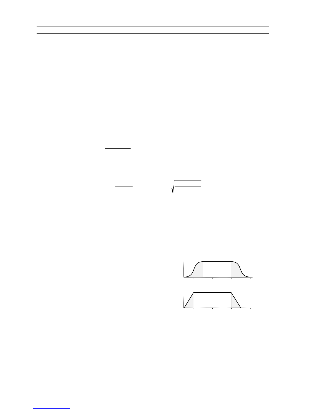
Calculating Move Times. The calculation for determining S-curve average accel and decel move times is
as follows (calculation method identical for S-curve and trapezoidal moves):
Time =
Velocity
A
avg
or Time =
2 Distance
∗
A
avg
Scaling affects the
acceleration (
A, AD
AA average acceleration (
AA, ADA
, etc.). See page 19 for details on scaling.
, etc.) the same as it does for the A maximum
NOTE: Equations for calculating jerk are provided on page 17.
Programming Example (see move profile drawings below)
; In this example, prog1 executes a pure S-curve and takes 1 second
; to reach a velocity of 5 rps; prog2 executes a trapezoidal profile
; and takes 0.5 seconds to reach a velocity of 5 rps.
SCALE0 ; Disable scaling
DEL Prog1 ; Delete program called prog1
DEF Prog1 ; Begin definition of prog1
MA0 ; Select incremental positioning mode
D40000 ; Set distance to 40,000
A10 ; Set max. accel to 10 revs/sec/sec
AA5 ; Set avg. accel to 5 revs/sec/sec
AD10 ; Set max. decel to 10 revs/sec/sec
ADA5 ; Set avg. decel to 5 revs/sec/sec
V5 ; Set velocity to 5 revs/sec
GO1 ; Execute motion
END ; End definition of prog1
DEL Prog2 ; Delete program called prog2
DEF Prog2 ; Begin definition of prog2
MA0 ; Select incremental positioning mode
D40000 ; Set distance to 40,000
A10 ; Set max. accel to 10 revs/sec/sec
AA10 ; Set avg. accel to 10 revs/sec/sec
AD10 ; Set max. decel to 10 revs/sec/sec
ADA10 ; Set avg. decel to 10 rev/sec/sec
V5 ; Set velocity to 5 revs/sec
GO1 ; Execute motion
END ; End definition
of program #2
V
0
V
0
Move profiles
123
123
S-Curve
T
Trapezoidal
T
16 Gemini GV6K/GT6K Command Reference
www.comoso.com
2
2
2
A
2
3
2
3
2
2
2
3
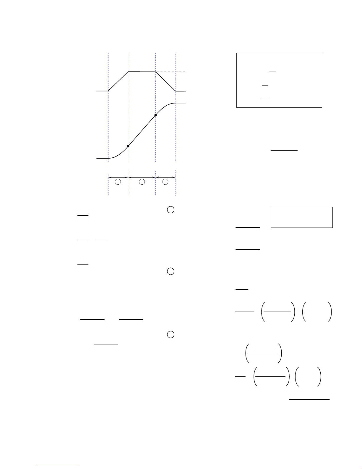
Calculating Jerk
Rules of Motion:
A
(Programmed Accel)
a
Zero Acceleration
V
(Programmed Velocity)
V
2
Assuming the accel profile starts
when the load is at zero velocity and
the ramp to the programmed velocity
is not compromised:
Zero Velocity
V
1
Ø
(zero)
t
1
A B C
t
2
t
3
Jerk
A = programmed acceleration
AA = average acceleration
V = programmed velocity
t1 =
A
J
A
t1 ≥ t ≥ Ø
a (t) = JA * t
J
* t
A
v (t) =
V
=
t
2
AA
V
=
t
3
AA
NOTE: t
A
J
- t2 = t1
3
A
B
t2 ≥ t > t1
d (t) =
a (t) = A
2
J
* t
A
6
A
v (t) = + A * (t - t1)
2J
V1 =
V2 = V -
J
* t
A
1
A
d (t) = + + V1 * (t - t1)
=
2
A
2 * J
2 * J
A
C
t3 ≥ t > t2
A
a (t) = A - (JA * (t - t2))
v (t) = V -
A
* t
J
A
6
V
d (t) = + - V * (t3 - t)
2AA
Starting at a Non-Zero Velocity
initial velocity, the move comprises two components: a constant velocity component, and
an s-curve component. Typically, the change of velocity should be used in the S-curve
calculations. Thus, in the calculations above, you would substitute “(VF - VO)” for “V”
(VF = final velocity, VO = initial velocity). This is shown in the jerk equation (right).
: If starting the acceleration profile with a non-zero
da
=
Jerk
dt
dv
=
dt
dx
= (x = distance)
v
dt
A2 * AA
=
= J
A
V (A-AA)
(A, AD, HOMAD, etc.)
(AA, ADA, HOMAA, etc.)
(V, HOMV, etc.)
a (t) = acceleration at time t
(t) = velocity at time t
v
(t) = distance at time t
d
1
A * (t - t
)
1
2
* (t3 - t)
J
A
2
JA (t3 - t)
6
= J
Jerk
=
A
A2 * AA
- VO) (A-AA)
(V
F
Introduction
www.comoso.com
17
Units of Measure and Scaling
Units of Measure without Scaling
Scaling is disabled (
• Stepper axes: All distance values entered are in commanded counts (sometimes referred to as motor
steps), and all acceleration, deceleration and velocity values entered are internally multiplied by the
DRES
command value.
• Servo axes:
Accel/Decel Revs/sec/sec *
Velocity Revs/sec *
Distance Counts **
SCALEØ
Motion Attribute Encoder or Resolver
* All accel/decel & velocity values are internally multiplied by the ERES command value.
** Distance is measured in the counts received from the feedback device.
) as the factory default condition:
Units of Measure
What is Scaling?
Scaling allows you to program acceleration, deceleration, velocity, and position values in units of measure
that are appropriate for your application. The
SCALE1
(
to enable,
SCALEØ
to disable). The motion type(s) you are using in your application determines
which scale factor commands you need to configure:
Type of Motion Accel/Decel Scaling Velocity Scaling Distance Scaling
Standard Point-to-Point Motion
Following
SCLA SCLV SCLD
SCLA SCLV
SCALE
command is used to enable or disable scaling
SCLD for follower distances
SCLMAS for master distances
When Should I Define Scaling Factors?
Scaling calculations are performed when a program is defined or downloaded. Consequently, you must
enable scaling (
DEF
(
), uploading (
SCLD, SCLV
RECOMMENDED
SCALE1
and
) and define the scaling factors (
TPROG
SCLMAS
), or running (
) are automatically saved in the Gem6K’s battery-backed RAM.
RUN
) the program. NOTE: All scaling settings (
: Place the scaling commands at the beginning of your program file, before the location
of any defined programs. This ensures that the motion parameters in subsequent programs in your program
file are scaled correctly. When you use Motion Planner’s scaling setup wizard, the scaling commands are
automatically placed in the appropriate location in your program file.
ALTERNATIVE
: Scaling factors could be defined via a terminal emulator just before defining or
downloading a program. Because scaling command values are saved in battery-backed RAM (remembered
after you issue a
command or cycle power to the Gem6K), all subsequent program definitions and
RESET
downloads will be scaled correctly.
• Scaling commands are not allowed in a program. If there are scaling commands in a program, the Gem6K
will report an error message (“COMMAND NOT ALLOWED IN PROGRAM”) when the program is downloaded.
• If you intend to upload a program with scaled motion parameters, be sure to use Motion Planner. Motion
Planner automatically uploads the scaling parameters and places them at the beginning of the program file
containing the uploaded program from the Gem6K. This ensures correct scaling when the program file is later
downloaded.
SCLD, SCLA, SCLV, SCLMAS
NOTES
) prior to defining
SCALE, SCLA
,
18 Gemini GV6K/GT6K Command Reference
www.comoso.com

Acceleration & Deceleration Scaling (SCLA)
Stepper Axes: If scaling is enabled (
SCALE1
), all accel/decel values entered are internally multiplied by
the acceleration scaling factor to convert user units/sec/sec to commanded counts/sec/sec.
The scaled values are always in reference in commanded counts, regardless of the existence
of an encoder.
Servo Axes: If scaling is enabled (
SCALE1
), all accel/decel values entered are internally multiplied by
the acceleration scaling factor to convert user units/sec/sec to encoder or resolver
counts/sec/sec.
All accel/decel commands (e.g., A, AA, AD,
HOMA, HOMAD, JOGA
, etc.) are multiplied by the
SCLA
command value.
As the accel/decel scaling factor (
changes, the resolution of the accel and decel
values and the number of positions to the right of
the decimal point also change (see table at right).
An accel/decel value with greater resolution than
allowed will be truncated (e.g., if scaling is set to
SCLA1Ø
, the
truncated to
A9.9999
A9.9
command would be
).
SCLA
)
SCLA value
1 - 9 ............................................ 0
10 - 99 ........................................ 1
100 - 999 .................................... 2
1000 - 9999 ................................ 3
10000 - 99999 ............................ 4
100000 - 999999........................5
(counts/unit/unit) Decimal Places
The following equations can help you determine the range of acceleration and deceleration values.
Axis Type Min. Accel or Decel (resolution) Max. Accel or Decel
Stepper
Servo
0.001 ∗DRES
SCLA
Encoder Feedback:
0.001 ∗ ERES
SCLA
999.9999 ∗DRES
SCLA
Encoder Feedback:
999.9999 ∗ ERES
SCLA
Velocity Scaling (SCLV)
Stepper Axes: If scaling is enabled (
velocity scaling factor to convert user units/sec to commanded counts/sec. The scaled
values are always in reference to commanded counts (sometimes referred to as “motor
steps”).
Servo Axes: If scaling is enabled (
velocity scaling factor to convert user units/sec to encoder or resolver counts/sec.
All velocity commands (e.g., V,
command value.
As the velocity scaling factor (
change (see table below). A velocity value with greater resolution than allowed will be truncated. For
example, if scaling is set to
SCLV Value
(counts/unit)
1 - 9
10 - 99
100 - 999
1000 - 9999
10000 - 99999
100000 - 999999
SCLV10
SCALE1
SCALE1
HOMV, HOMVF, JOGVH, JOGVL
SCLV
) changes, the velocity command's range and its decimal places also
, the
), all velocity values entered are internally multiplied by the
), all velocity values entered are internally multiplied by the
, etc.) are multiplied by the
V9.9999
Velocity Resolution
(units/sec)
1
0.1
0.01
0.001
0.0001
0.00001
command would be truncated to
Decimal Places
0
1
2
3
4
5
V9.9
SCLV
.
Introduction
www.comoso.com
19

Use the following table to determine the maximum velocity for your product type.
Max. Velocity for Stepper Axes Max. Velocity for Servo Axes
50 revs/sec 200 revs/sec
: These velocity limitations are hardware based. Make sure the velocity scaling value used with the desired velocity
NOTE
(V command) does not exceed these velocities. The Gem6K will generate an error message if you try to exceed these
maximums. The maximum servo velocity may also be limited when using encoder feedback, depending on the encoder
resolution `used. Refer to the Gem6K Hardware Installation Guide for the maximum encoder input frequency.
Distance Scaling (SCLD and SCLMAS)
Stepper Axes: If scaling is enabled (
SCALE1
), all distance values entered are internally multiplied by the
distance scaling factor to convert user units to commanded counts (“motor steps”).
Servo Axes: If scaling is enabled (
SCALE1
), all distance values entered are internally multiplied by the
distance scaling factor to convert user units to encoder or analog input counts.
All standard motion distance commands (e.g.,
command value. The only exception is for master distance values (see table below):
SCLD
Scaling for Following Motion:
SCLMAS command defines the master’s distance scale factor. The Following-related commands that are affected
by SCLD and SCLMAS are listed in the table below.
Commands Affected by Master Scaling (
FMCLEN: Master Cycle Length
FMCP: Master Cycle Position Offset
FOLMD: Master Distance
FOLRD: Follower-to-Master Ratio (Denominator)
GOWHEN: Conditional GO (left-hand variable is PMAS)
TPMAS & [
TVMAS & [
SCLD
As the
]: Position of Master Axis
PMAS
]: Velocity of Master Axis
VMAS
SCLMAS
or
scaling factor changes, the distance command’s range and its decimal places also
The SCLD command defines the follower axis distance scale factor, and the
D, PSET, REG, SMPER, STRGTD
SCLMAS
Commands Affected by Follower Scaling (
)
FOLRN: Follower-to-Master Ratio (Numerator)
FGADV: Geared Advance
FSHFD: Preset Phase Shift
GOWHEN: Conditional GO (left-hand variable ≠ PMAS)
TPSHF & [
TPSLV & [
PSHF
PSLV
) and are multiplied by the
SCLD
]: Net Position Shift of Follower
]: Position of Follower Axis
change (see table below). A distance value with greater resolution than allowed will be truncated. For
example, if scaling is set to
SCLD4000
D105.2776
, the
command would be truncated to
D105.277
)
.
SCLD or SCLMAS
(counts/unit)
1 - 9 1.0 0 - ±999999999 0
10 - 99 0.10 0.0 - ±99999999.9 1
100 - 999 0.010 0.00 - ±9999999.99 2
1000 - 9999 0.0010 0.000 - ±999999.999 3
10000 - 99999 0.00010 0.0000 - ±99999.9999 4
100000 - 999999
NOTE FRACTIONAL STEP TRUNCATION NOTE
Value
If you are operating in the incremental mode (MAØ), or specifying master distance values with
FOLMD, when the distance scaling factor (SCLD or SCLMAS) and the distance value are multiplied,
a fraction of one step may be left over. This fraction is truncated when the distance value is used
in the move algorithm. This truncation error can accumulate over a period of time, when
performing incremental moves continuously in the same direction. To eliminate this truncation
problem, set SCLD or SCLMAS to 1, or a multiple of 10.
20 Gemini GV6K/GT6K Command Reference
Distance Resolution
(units)
0.00001 0.00000 - ±9999.99999 5
Distance Range *
(units)
www.comoso.com
Decimal
Places

Scaling Example — Steppers (GT6K)
We configure for a 25,000 step/rev system attached to 5-pitch leadscrew. The user wants to program
motion parameters in inches; therefore the scale factor calculation is: 25,000 steps/rev x 5 revs/inch =
125,000 steps/inch. For instance, with a scale factor of 125,000, the operator could enter a move distance
value of 2.000 and the controller would send out 250,000 pulses, corresponding to two inches of travel.
SCALE1 ; Enable scaling
DRES25000 ; Set drive resolution to 25,000 steps/rev
SCLD125000 ; Allow user to enter distance in inches
SCLV125000 ; Allow user to enter velocity in inches/sec
SCLA125000 ; Allow entering accel/decel in inches/sec/sec
DRESET ; Reset the drive so the DRES value is accepted
Scaling Example — Servos (GV6K)
We configure for a 4,000 count/rev servo motor/drive system (using a 1000-line encoder) attached to a 5pitch leadscrew. The user wants to position in inches; therefore, the scale factor calculation is 4,000
counts/rev x 5 revs/inch = 20,000 counts/inch.
SFB1 ; Select encoder feedback
ERES4000 ; Set encoder resolution to 4000 steps/rev (post quadrature)
SCALE1 ; Enable scaling
SCLD20000 ; Allow user to enter distance values in inches
SCLV20000 ; Allow user to enter velocity values in inches/sec
SCLA20000 ; Allow user to enter accel/decel values in inches/sec/sec
DRESET ; Reset the drive so the DRES value is accepted
Scaling Example — Following
Typically, the master and follower scale factors are programmed so that master and follower units are the
same, but this is not required. Consider the scenario below as an example.
The master is a 1000-line encoder (4000 counts/rev post-quadrature) mounted to a 50 teeth/rev pulley
attached to a 10 teeth/inch conveyor belt, resulting in 80 counts/tooth (4000 counts/50 teeth = 80
counts/tooth). To program in inches, you would set up the master scaling factor with the
command (80 counts/tooth ∗ 10 teeth/inch = 800 counts/inch).
The follower is a servo motor with position feedback from a 1000-line encoder (4000 counts/rev). The
motor is mounted to a 4-pitch (4 revs/inch) leadscrew. Thus, to program in inches, you would set up the
follower scaling factor with the
SCLD16000
command (4000 counts/rev ∗ 4 revs/inch = 16000
counts/inch).
SCALE1 ; Enable scaling
SCLMAS800 ; Master scaling (80 counts/tooth * 10 teeth/inch = 800 counts/inch)
SCLD16000 ; Follower scaling (4000 counts/rev * 4 revs/inch = 16000 counts/inch)
SCLMAS800
Introduction
www.comoso.com
21

www.comoso.com
Special Programming
Characters
%
Type Multi-Tasking
Syntax <a_>i%<command>
Units i = task number
Range 1-10
Default 1
Response n/a
See Also
LOCK, [SWAP], [TASK], TSKAX, TSKTRN, TSWAP, TTASK
Task Identifier
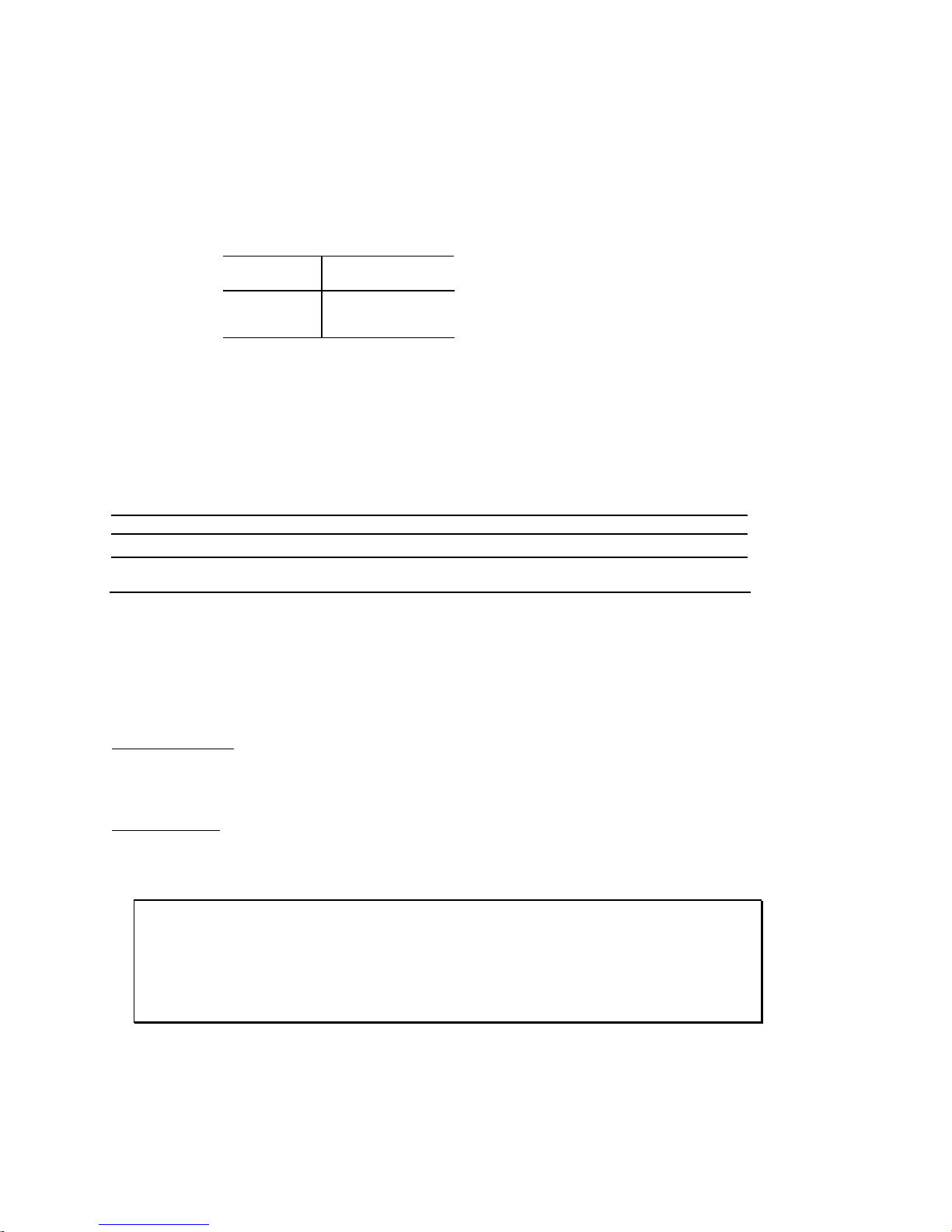
Use the Task Identifier (%)
prefix to specify that the
associated command will affect
the indicated task number. For
most simple multi-tasking
applications, the
prefix is
%
used to start a program running
in a specific task. For example,
the drawing on the right
illustrates how the
1%move1
command starts the program
called “
(specified with the
move1
” in task 1
prefix).
1%
1%move1
Gx6K Drive
Supervisor
Assign Task 1 to
execute the
"move1" program
Task 1
Execute the
"move1" program.
Product Rev
GT6K 6.0
GV6K 6.0
Program MemoryTask Management
Program: move1
DEF move1
---
---
--END
Command Descriptions 23
www.comoso.com
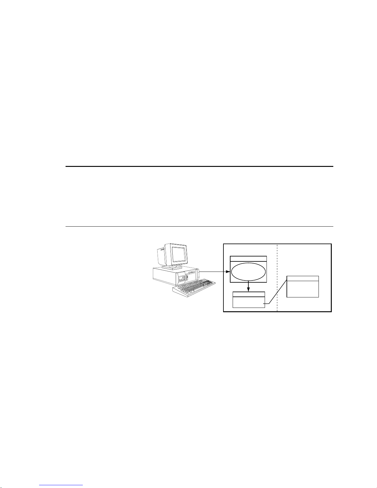
Because the
associated command will affect, new tasks can be
started from within other tasks, as shown in the
drawing on the right.
Within a program in a task, it is not necessary to use
the % prefix unless trying to initiate a program or
command in a different task. For example, if the
program running in task 3 executes a
fill
command, only task 3 is placed into
If the
fill
command, task 3 executes the command, but the
2%PS
program being executed in task 2 is paused, not task 3.
prefix specifies the task number that the
%
COMEXC1
COMEXC1
mode.
program running in task 3 also executes a
Gx6K Drive
Program MemoryTask Management
Supervisor
Running "main"
Task 1
Execute "move1"
Task 3
Execute "fill"
Program: main
DEF main
---
--1%move1
---
--END
Program: move1
DEF move1
---
--3%fill
---
--END
How the Task Supervisor Works: The “Task Supervisor” (also referred to as Task Ø
execution environment. It contains the command buffer and parser. Immediate commands and commands
executed from the communications buffer are implicitly directed to affect the supervisor unless exp licitly
directed to a task with the
prefix. Only the supervisor executes buffered commands from the
%
communications buffer. If the supervisor is executing a program, incoming commands will be buffered,
not executed. If the supervisor is not executing a program, it will execute commands from the input
command buffer, even if the other tasks are executing programs. If a command in the command buffer has
a task prefix, it is still executed by the supervisor, but affects the task specified by the prefix.
) is the main program
[ ! ]
Type Operator (Other)
Syntax <a_>!<command>
Units n/a
Range n/a
Default n/a
Response n/a
See Also COMEXC
mmediate Command Identifier
Product Rev
GT6K 6.0
GV6K 6.0
The Immediate Command Identifier (!) changes a buffered command into an immediate command. All
immediate commands are processed immediately, even before previously entered buffered commands.
All Gem6K commands are buffered.
The commands that use the
identifier are identified in the
!
portion of the command description.
Syntax
NOTE
A command with the ! prefix cannot be stored in a program.
24 Gemini GV6K/ GT6K Command Reference
www.comoso.com

[ @ ]
Type Operator (Other)
Syntax @<command><field1>
Units n/a
Range n/a
Default n/a
Response n/a
See Also ANIEN, ANIRNG, INEN, INLVL, OUT, OUTALL, OUTEN, OUTLVL, TANI,
TANO, TIN, TIO, TOUT
Global Command Identifier
Product Rev
GT6K 6.0
GV6K 6.0
The Global Command Identifier (@) is used to set the value of all fields to the value entered only in the first
field. For example,
commands can use the
;
Type Operator (Other)
Syntax ;<this is a comment>
Units n/a
Range n/a
Default n/a
Response n/a
See Also None
@OUT1 sets output #1 on for all I/O bricks. If you have any doubts about which
symbol, refer to the
@
Begin Comment
portion of the command description.
Syntax
Product Rev
GT6K 6.0
GV6K 6.0
The Begin Comment (;) command is used to comment application programs. The comment begins with a
semicolon (
) and is terminated by a command delimiter. The comment is not stored in a program. An
;
example of using the comment delimiter is as follows:
DEF pick ; Begin definition of program pick<cr>
$
Type Operator (Other)
Syntax <a_><!>$<t>
Units t = text name
Range Text name of 6 characters or less
Default n/a
Response n/a
See Also DEF, DEL, END, GOSUB, GOTO, JUMP, RUN, TLABEL
Label Declaration
Product Rev
GT6K 6.0
GV6K 6.0
The Label Declaration ($) command defines the current location as the label specified. A label consists of 6
or fewer alpha-numeric characters and must start with an alpha-character, not a number. Labels can only be
defined within a program or subroutine. The
label. The
deleted by a
command can also be used to start executing statements at a label. The label cannot be
RUN
command. However, when the program that contains the label is deleted, all labels
DEL
GOTO, GOSUB
or
commands can be used to branch to a
JUMP
contained within the program will be deleted.
NOTE: The maximum number of labels possible is 600.
A label declaration cannot consist of any of the following characters:
!, _, #, $, %, ^, &, *, (, ), +, -, {, }, \, |, ", :, ;, ', <, >, ,, ., ?, /, =
A label cannot have the same name as a Gem6K command. For example, $A and
NOTE:
are illegal
$A123
labels.
Command Descriptions 25
www.comoso.com

Example
DEF pick ; Begin definition of program called pick
GO1 ; Initiate motion
IF(VAR1=5) ; If variable 1 = 5 then do commands between IF and ELSE,
; otherwise commands between ELSE and NIF
GOTO pick1 ; Goto label pick1
ELSE ; Else part of IF command
GOTO pick2 ; Goto label pick2
NIF ; End IF command
$pick1 ; Label declaration for pick1
TAS ; Report axis status
BREAK ; Break out of current subroutine or program
$pick2 ; Label declaration for pick2
TPC ; Report commanded position
END ; End program definition
RUN pick ; Execute program named pick
[ # ]
Type Operator (Other)
Syntax <a_>!#<i>
Units i = number of commands to execute from the buffer
Range i = 1 - 200
Default 1
Response n/a
See Also DEF, HELP, STEP, TRACE, TRANS
Step Through a Program
Product Rev
GT6K 6.0
GV6K 6.0
This command controls the execution of a program or sequence when the single step mode is enabled
(
buffer will be executed. A
). Each time you enter the
STEP1
command followed by a delimiter, i commands in the sequence
!#<i>
followed by a delimiter will cause one command to be executed.
!#
Single step mode can be advantageous when trying to debug a program.
Example:
DEF tst ; Begin definition of program named tst
V1 ; Set velocity to 1 unit/sec
A10 ; Set acceleration to 10 units/sec/sec
D1 ; Set distance to 1 unit
GO1 ; Initiate motion
OUT11X1 ; Turn on on-board programmable outputs 1, 2, and 4,
; leave 3 unchanged
END ; End program definition
STEP1 ; Enable single step mode
RUN tst ; Execute program named tst
After entering the command
NOTE:
no action will occur because single step mode has been enabled.
RUN
Single step operation is as follows:
!#2 ; First 2 commands in the program tst are executed,
; commands to be executed are V1 and A10.
!# ; Execute 1 command from program; command to execute is D1
!#1 ; Execute 1 command from program; command to be executed is GO1
!#2 ; Execute 2 commands from program; commands to be executed are
; OUT11X1 and END
26 Gemini GV6K/ GT6K Command Reference
www.comoso.com

'
Type Operator (Other)
Syntax !'<numeric data>
Units Numeric data is command-dependent
Range Numeric data is command-dependent
Default n/a
Response n/a
See Also [ READ ], VARI, VARS
Enter Interactive Data
Product Rev
GT6K 6.0
GV6K 6.0
To enter data interactively, two operations must occur. First, numeric information must be requested.
Requesting the numeric information is accomplished with the
numeric variable to place the data into, and the
specifies the string variable to transmit before the data is
y
entered. Numeric information can also be requested by placing the
argument (e.g.,
A(READ1),12.52,(READ2),5.62
). After the data has been requested, a numeric
VARx=READy
READ
response must be provided. The numeric response must be preceded by the interactive data specifier (
command. The x specifies the
command in place of a command
)
!'
and followed by a delimiter (<cr> or <lf>).
Command processing will pause while waiting for data.
Example:
VARS1="Enter the count > " ; Set string variable 1 equal to the message
VAR5=READ1 ; Transmit string variable 1, and wait for numeric data in the
; form of !'<data>. Once numeric data has been received, place
; it in numeric variable 5
!'65.12 ; Variable 5 will receive the value 65.12
[ . ]
Type Operator (Other)
Syntax <command>.i
Units i = bit number
Range Command-dependent
Default None
Response n/a
See Also [ AS ], [ ER ], ERROR, [ IN ], INEN, INLVL, [ INO ], INTHW, LIMLVL,
[ MOV ], ONIN, ONUS, OUT, OUTEN, OUTLVL, POUT, [ SS ], TAS, TER, TIN,
TINO, TIO , TOUT, TSS, TUS, [ US ]
Bit Select
Product Rev
GT6K 6.0
GV6K 6.0
The Bit Select (.) operator specifies which bit to select. The primary purpose of this command is to let the
user specify a specific bit (or range), instead of having to type in an entire bit string.
When using the bit operator in a comparison, the bit operator must always come to the left of the
comparison. For example, the command
Command Shortcut Examples (affect only one binary bit location):
• Activate outputs at I/O location Brick 3, I/O point 9:
• Enable analog input at I/O location Brick 2, I/O point 2:
• Enable error-checking bit 6 for task 3:
Example:
VARB2=ER.12 ; Error status bit 12 assigned to binary variable 2
VARB2 ; Response (if bit 12 is set to 1):
2OUT.5=1 ; Activate the output at location Brick 2, I/O point 5
Command Descriptions 27
; *VARB2=XXXX_XXXX_XXX1_XXXX_XXXX_XXXX_XXXX_XXXX
IF(AS.12=b1)
is legal, but
www.comoso.com
IF(b1=AS.12)
3OUT.9=1
2ANIEN.2=E
3%ERROR.6=1
is illegal.

[ " ]
Type Operator (Other)
Syntax "<message>" (see below for possibilities)
Units n/a
Range n/a
Default n/a
Response n/a
See Also DWRITE, VARS, WRITE, WRVARS
Begin and End String
Product Rev
GT6K 6.0
GV6K 6.0
There are three commands that deal with string variables, or messages. The first of these commands is the
command. This command sets a string variable equal to a specific message (e.g.,
VARS
part count"
WRITE
first day of the rest of your life"
Syntax possibilities:
There are three ASCII characters that cannot be used within the quotes (
be specified in the string by using the backslash character (
for the character. For example, if you wanted to display the message
use the following syntax:
). The message must be placed in quotes for it to be recognized. The same can be said for the
and
DWRITE
commands. Their messages must also be placed in quotes (e.g.,
).
VARSn="<message>"
WRITE"<message>"
DWRITE"<message>"
WRITE"\34WHY ASK WHY\34"
where n equals the string variable number
:, "
) in combination with the ASCII decimal value
\
"WHY ASK WHY"
.
VARS1="Enter
WRITE"Today is the
, and ;). These characters can
in quotes, you would
An ASCII table is provided in Appendix B. Common characters and their ASCII equivalent value:
Character Description ASCII Decimal Value
<lf> Line Feed 10
<cr> Carriage Return 13
" Quote 34
: Colon 58
; Semi-colon 59
\ Backslash 92 (cannot be used with DWRITE)
[ \ ]
Type Operator (Other)
Syntax See below
Units n/a
Range n/a
Default n/a
Response n/a
See Also VARS, WRITE, WRVARS
ASCII Character Designator
Product Rev
GT6K 6.0
GV6K 6.0
The ASCII Character Designator (\) operator is used to place a character in a string that is normally not
represented by a keyboard character. The (
commands. The syntax for the (
WRITE"\<i>"
VARS1="\<i>"
, Where
, Where
<i>
<i>
) operator is as follows:
\
is the ASCII decimal equivalent of the character to be placed in the string.
is the ASCII decimal equivalent of the character to be placed in the string.
) operator can be used within the
\
There are three ASCII characters that cannot be used within the quotes (
be specified in the string by using the backslash character (
) in combination with the ASCII decimal value
\
:, ;
VARS
or the
WRITE
, and "). These characters must
for the character.
28 Gemini GV6K/ GT6K Command Reference
www.comoso.com
 Loading...