

Page 1
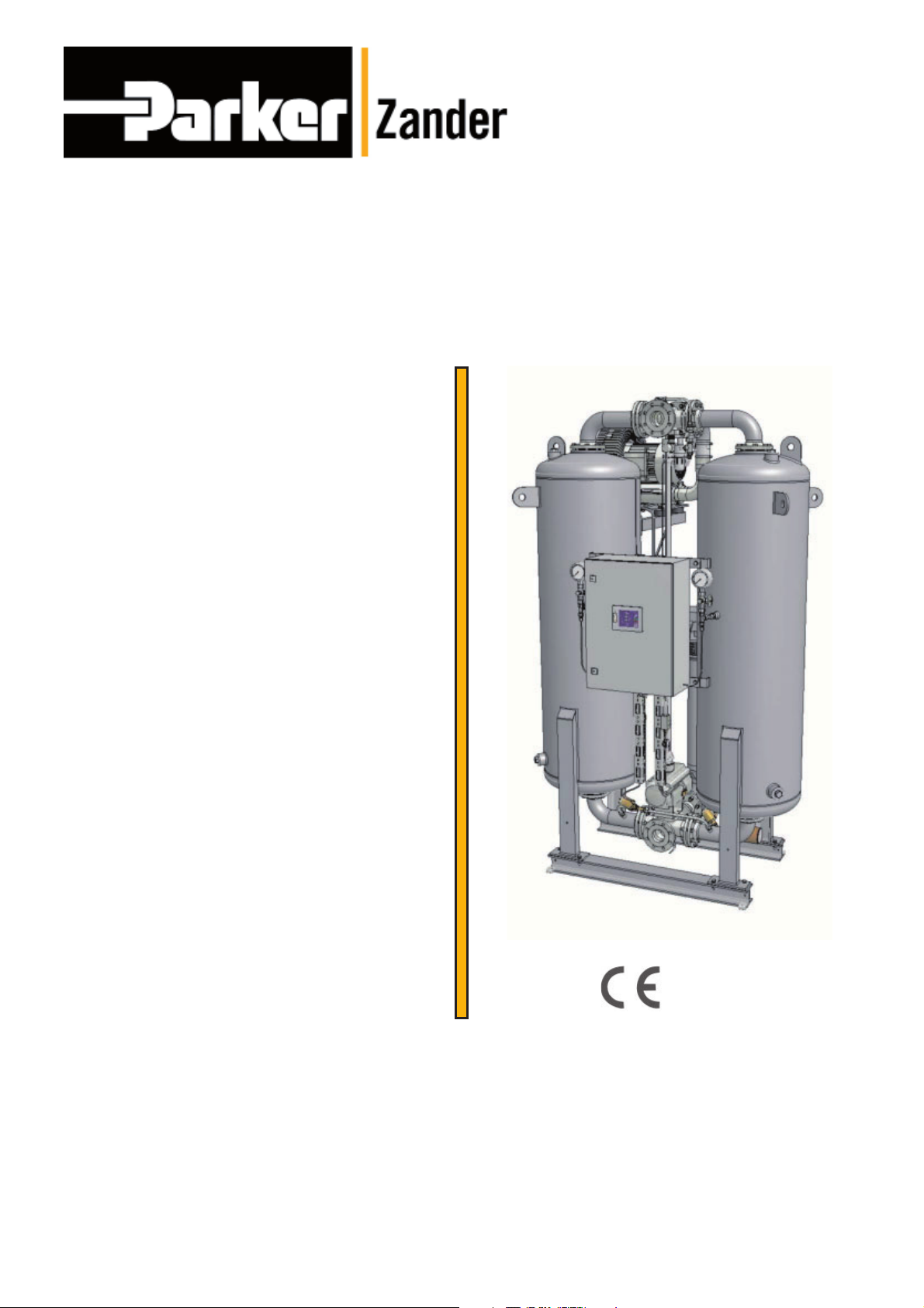
Adsorption dryer
WVM 40-1450
Operating manual
Revision 04—06_2018 /EN
Cod: 398H271785
Page 2

Page 3

EN | Operating manual
Index
Machine Passport 5
General information 6
Manufacturer’s details ............................................................................................................... 6
Dryer Speci cations .................................................................................................................. 6
About these operating instructions ........................................................................................... 7
For your own safety 8
Signs and danger zones at the dryer ....................................................................................... 8
Intended use of the dryer ........................................................................................................ 10
General safety notes ............................................................................................................... 10
Safety notes on speci c operating phases ............................................................................. 11
Technical product description 13
Summary drawing ................................................................................................................... 13
Function .................................................................................................................................. 15
Options 18
Transportation, installation and storage 20
What to do in the case of transport damage occurring? ....................................................... 20
Transporting dryer to its location of installation ...................................................................... 21
Storage ................................................................................................................................... 24
Installation 26
Requirements for installation ..................................................................................................26
Installation of pipelines ........................................................................................................... 28
Connection of electrical components ..................................................................................... 29
Start-up 30
Requirements for initial commissioning ................................................................................ 30
Overview of the operating and display elements .................................................................... 30
Commissioning of the dryer .................................................................................................... 31
Preparation for commissioning ............................................................................................... 32
Monitoring dryer operation 35
Notes on speci c operating situations.................................................................................... 35
Shutdown and restart dryer 36
Emergency shutdown .............................................................................................................36
Stopping the dryer ................................................................................................................. 36
Depressurising and shutting down the dryer .......................................................................... 37
If work is to be carried out on the electrical system ............................................................... 37
Restart .................................................................................................................................... 38
Maintenance and repair of the dryer 39
Notes on maintenance ............................................................................................................ 39
Regular maintenance taskse ................................................................................................... 40
Daily maintenance tasks ......................................................................................................... 41
Monthly maintenance ............................................................................................................. 41
Six-monthly maintenance work .............................................................................................. 41
Maintenance work to be completed every 12 months ............................................................ 42
Maintenance work to be completed every 24 months ............................................................ 44
Maintenance work to be completed every 48 months ............................................................ 44
Identify and eliminate faults 48
WVM 40 -1450 3
Page 4

EN | Operating manual
Notes on error messages and errors ...................................................................................... 48
Appendix: Technical Documents 49
Technical data – overview of standard dryers ......................................................................... 50
Spare parts list ........................................................................................................................ 52
4 WVM 40 -1450
Page 5

EN | Operating manual Machine Passport
Machine Passport
Machine Type WVM
Order No.
Catalogue No.
Manufacture No.
Vessel 1 No.
Vessel 2 No.
Date of Manufacture
The operator is obliged to
◊ enter missing unit data in the above table,
◊ regularly update the unit data.
The above device speci cations are necessary to quickly identify the dryer and its components and facilitate servicing.
Other important data regarding the dryer such as permitted operation pressure and electrical
power are found on the type plate. (For location of the type plate, see page 8.)
WVM 40 -1450 5
Page 6

EN | Operating manual General information
General information
Manufacturer’s details
Parker Hannifi n Manufacturing S.r.l.
Sede Legale: Via Privata Archimede, 1- 2009 Corsico (MI) Italy
Sede Operativa: Gas Separation and Filtration Division EMEA - Strada Zona Industriale, 4
35020 S.Angelo di Piove (PD) Italy
tel +39 049 971 2111- fax +39 049 9701911
Web-site: www. parker.com/hzd
e-mail: [email protected]
Dryer Specifi cations
Scope of delivery
Adsorption dryer, consisting of:
◊ 2 vessels lled with desiccant
◊ 1 Heater
◊ 1 Vacuum pump
◊ 1 Switch cabinet including control system
◊ 1 Key for switch cabinet
◊ Piping and silencer
Supplementary documents (standard scope)
◊ Operating manual (i.e. this document)
◊ Operating manual of pertaining controller
◊ Operating manual of tted vacuum pump
◊ Technical documents (see appendix):
— Dimensional drawing
— Process diagram
— Pneumatic diagram of the control air unit
◊ Electrical diagramsi
Notes on supplementary documents
Supplementary documents such as operating manuals for options or pertaining components
must always be heeded. They contain additional information, e.g. regarding maintenance,
and are therefore necessary for safe operation of the plant.
Notes on upstream and downstream fi lters
Upstream and downstream lters are not contained in the standard scope of delivery of the
dryer. For this reason, the operator must install at least an upstream lter. Please also heed
the notes regarding the intended use on page(10)
Warranty notes
In the following cases, the warranty shall be void:
◊ If aggressive media in the compressed air and in the environment cause corrosion damage
and functional faults on the dryer.
◊ If the dryer is used without prior approval and con rmation in writing by the manufactur-
er for purposes other than those speci ed in these operating instructions or contractually
agreed.
◊ If preset parameters (e. g. on the control system etc.) are changed without prior approval
and con rmation in writing by the manufacturer.
◊ If the dryer is transported or stored incorrectly.
◊ If the dryer is sited and installed incorrectly.
6 WVM 40 -1450
Page 7

EN | Operating manual General information
◊ If the dryer is repaired or maintained incorrectly.
◊ If the dryer is operated by personnel that does not have the requisite quali cations.
◊ If modi cations are carried out on the dryer, the manufacturer did not approve that.
◊ If notes given in pertaining operating manuals were not heeded.
In the event of non-compliance the manufacturer will not accept any liability for any consequential damage whatsoever.
About these operating instructions
These operating instructions contain basic information on the safe use of the dryer.
Characters and symbols used
Work steps that you have to carry out in the sequence stated are marked by black tri-
angles.
◊ Lists are marked by a small box.
Note:
These notes provide you with hints and information on the safe and effi cient
handling of machines and devices.
Warning!
These safety notes warn against damage to property and help you to avoid
such damage.
Danger!
These danger notes with a grey background warn against personal injury and/
or danger to life and limb; danger notes help you to avoid serious or life-threatening situations for yourself and/or third parties.
Target group of these operating instructions
These operating instructions are intended for all persons working on and using the dryer. We
assume that all such persons are specialist personnel, e.g. tters or electricians.
Operating instructions: handling
These operating instructions must be continuously available at the site where the dryer is
used. We recommend to prepare a copy and to keep the same in a safe and freely accessible
place next to the dryer. Keep the original document in a safe place.
WVM 40 -1450 7
Page 8
EN | Operating manual For your own safety
For your own safety
The dryer has been built in accordance with the state of the art and the recognized technical
safety regulations. Nevertheless, there is a risk of personal injury and damage to property
when the dryer is used, if:
◊ it is operated by non-quali ed personnel,
◊ not used within its intended design speci cations,
◊ is repaired or maintained incorrectly.
Note:
For your own safety and to prevent machine damage, please note the information and safety notes in these operating instructions when working with the
dryer.
Signs and danger zones at the dryer
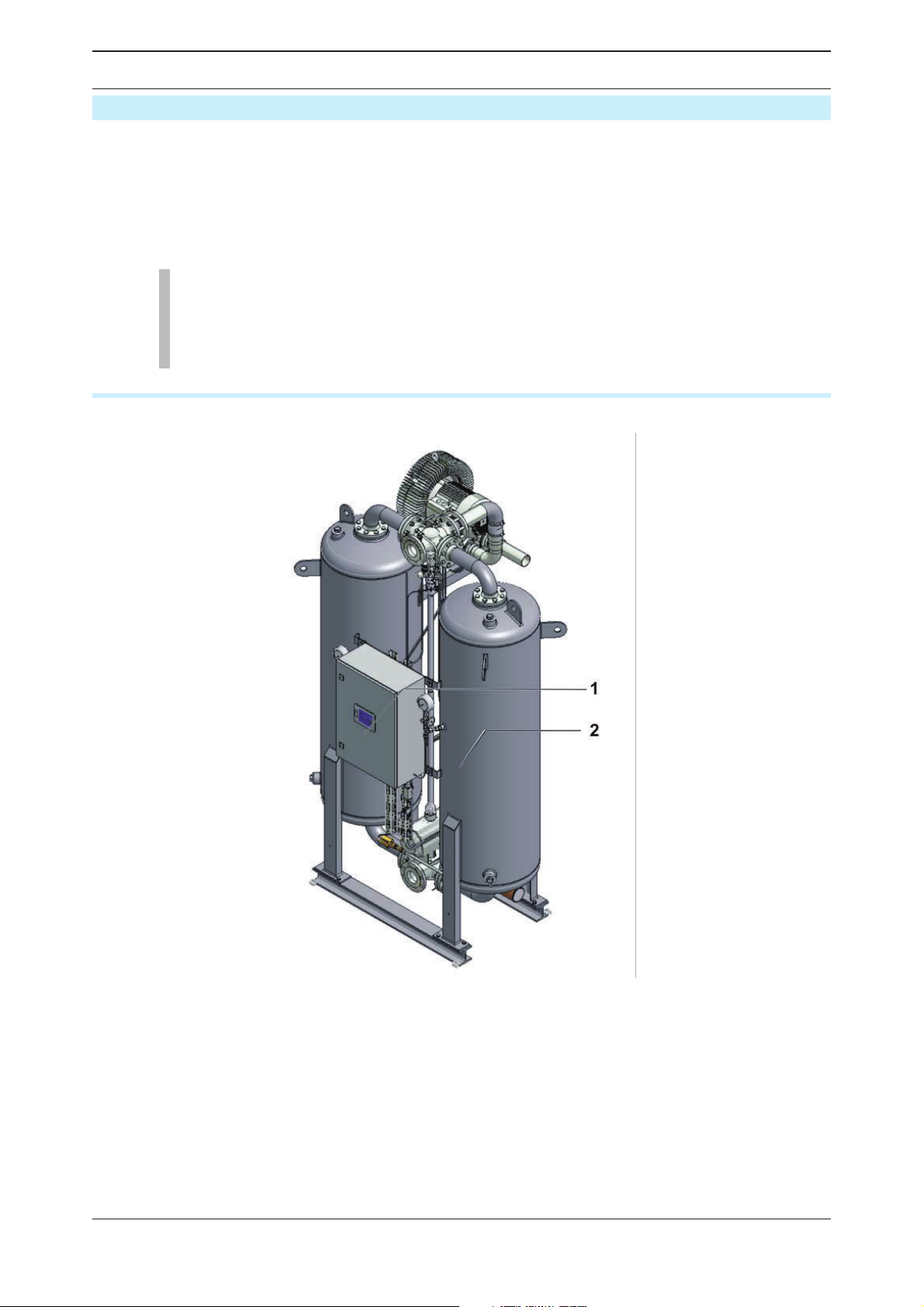
Signs and instructions
1 Type plate
2 Vessel plate
Please note the above plates and instructions attached to the dryer. Make sure they are
always complete and readable.
8 WVM 40 -1450
Page 9
EN | Operating manual For your own safety
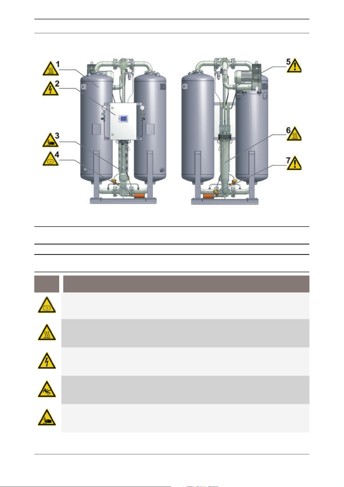
Danger zones at the dryer
1,6
Symbol Danger zone
Risk of injury from hot vessel and piping
surfaces
2 Risk of injury by high voltage 5 Risks of injury by hot regeneration gas ow
Risk of injury from crushing by shaft during
3
switching
4 Risk of injury by suddenly escaping gas
7 Risk of injury by blocked silencer
Excess pressure warning
The entire dryer is under pressure. Air that is suddenly released through expansion
and relief valves can lead to serious injury.
Hot surfaces
During operation, certain surfaces of the dryer reach temperatures above 120 °C.
At insulated dryers, screw connections might protrude from the insulation.
Voltage
Various parts of the dryer are live. These components may only be connected,
opened and serviced by authorised technical personnel.
Risk of slipping
During the emptying and lling of the vessels, there is a risk of injury from slipping
on spilt desiccant.
Risk of crushing
At the universal shaft and the drives, there is a risk of injury from crushing during
the switching from absorption to regeneration.
WVM 40 -1450 9
Page 10

EN | Operating manual For your own safety
Intended use of the dryer
The dryer is exclusively intended for drying compressed air. Depending on de ned input
conditions, it dries compressed air for industrial use.
The dryer is designed for compressed air, which is free from aggressive water, oil, and solid
matter constituents.
Note:
Never operate the dryer without upstream fi lter. For this reason, the operator
must install an appropriate upstream fi lter (degree of fi ltration < 0.01 μm, residual oil contents < 0.001 mg/m³).
We recommend that you install an additional downstream fi lter to protect the
downstream compressed air network against desiccant residues.
Suitable fi lter solutions can be obtained from the manufacturer.
As standard, the dryer is intended to be sited within a building and protected against the weather. When it is sited in the open air (option), the instructions on page 18 must be complied
with.
The dryer may be operated only in accordance with the data on the type plate and in accordance with the contractual conditions.
Suspected misuse
The dryer must not be misused as a climbing aid! Pipes, valves, and similar ttings have not
been designed for such loads. They could fracture, tear off, or become damaged in another
way.
General safety notes
For your own safety, when carrying out any work on the dryer comply with all
applicable national safety regulations!
Personnel qualifi cation
Only authorized and quali ed specialist personnel may be tasked with the work on the dryer
described in these operating instructions. The electropneumatic switch cabinet in particular
must be opened and serviced by an instructed trained electrician only..
Conversions and modifi cations
Without prior approval by the manufacturer, no conversions and modi cations must be made
to the dryer! Any non-approved modi cations may restrict the operational safety of the dryer
and cause damage to property or personal injury.
Notes on desiccant handling
The used desiccant is perfectly safe when new. Increased dust formation can nevertheless
occur when desiccant is lled into or removed from a vessel . Therefore, heed the following
hints:
◊ Wear a dust mask and eye protection when lling desiccant into the vessels!
◊ Collect spilt desiccant immediately! There is a risk of injury from slipping on spilt desiccant!
Note:
For information on how to dispose of used desiccant refer to page 12.
10 WVM 40 -1450
Page 11

EN | Operating manual For your own safety
Safety notes on specifi c operating phases
Transportation and siting
◊ Only use suitable and technically perfect lifting gear with a suf cient carrying capacity.
◊ Carefully secure the dryer during transportation.
Commissioning of the dryer
Risk of injury from suddenly escaping gas!
While the unit is under pressure, never remove any components or otherwise
interfere with the dryer! Suddenly escaping gases can lead to serious injury!
Prior to any work, release all pressure from the unit.
◊ Execute the stipulated tests and checks.
◊ On no account should the factory settings of the control programme be altered without
consulting the manufacturer.
◊ Prior to commissioning make sure there are no tools or foreign objects in, on or near the
dryer that could turn into a hazard for commissioning the dryer.
Emergency shutdow
◊ In any emergency, proceed as described in the section on page 36
Monitoring of the operation
Warning against sudden air ejection!
During expansion the pressure is released suddenly through the muffl er:
◊ A loud cracking noise occurs which can injure your hearing.
◊ Particles carried in the air can injure your eyes or skin.
Always wear eye and ear protection, therefore, when you are in the vicinity of
the dryer!
◊ Operate the dryer only within the permitted limits (see type plate). If the unit is operated
under conditions where the de ned limit values are exceeded, it is exposed to stresses for
which it is not designed. This can result in malfunction or failure of the dryer.
◊ The higher the capacity of the dryer, the more noise it produces during operation. The oper-
ator must therefore provide suitable protective equipment (earmuffs).
◊ The dryer must be regularly inspected for visible damage. Any observed changes, includ-
ing changes in the operation behaviour, must be immediately reported to the responsible
person.
◊ In the event of an emergency and if safety-relevant malfunctions are observed (e.g. escap-
ing compressed air, higher noise level, defective components), the dryer must be immediately switched off (see page 36). The unit may only be restarted after all defects have been
eliminated.
WVM 40 -1450 11
Page 12

EN | Operating manual For your own safety
Servicing and troubleshooting the dryer
Risk of injury from escaping compressed air!
Never remove any parts of the dryer, or manipulate the same in any way, as
long as the unit is pressurised! Suddenly escaping compressed air might cause
serious injuries.
Prior to any work, release all pressure from the unit.
◊ Carry out all maintenance work only when the plant has been shut down and depressur-
ised!
◊ Do not modify the factory settings of the control system in any way without prior consulta-
tion with the manufacturer.
◊ Bolt connections must be undone with care! Note ram pressure values! Otherwise emerging
media may cause personal injury.
◊ Never carry out welding work on a vessel or modify the same in any way!
◊ Never use pipes and ttings as steps or holding points! The components might fracture, or
the distortions which occur may cause internal damage on the dryer. There is a risk of injury
by slipping off the components, components breaking off, and expanding compressed air!
◊ Never leave tools, loose parts or cloths in, at or on the dryer.
◊ Following maintenance work, always check all ange and bolt connections for leakage and
secure seating.
◊ Only use replacement parts that are suitable for the relevant function and meet the techni-
cal requirements stipulated by the manufacturer. This is always the case, if you use original
replacement parts only.
Removal and disposal
Hazard due to a sudden release of pressure!
Never remove any parts of the dryer, or manipulate the same in any way, for as
long as the dryer is still pressurised! A sudden escape of pressure may cause
serious injuries.
Depressurise the plant before carrying out any work on the dryer.
Notes on the disposal of used desiccant
As the used desiccant is contaminated with various substances, its properties differ from
those of new desiccant. For this reason, the manufacturer or supplier of desiccant cannot
give any information on the used product.
Deliver used desiccant to a controlled dumping while heeding local of cial regulations.
Waste codes
◊ New product: 060899 (European waste code).
◊ Used product: These codes are governed by the industrial use and must therefore be deter-
mined by the waste originator.
12 WVM 40 -1450
Page 13
EN | Operating manual Technical product description
Technical product description
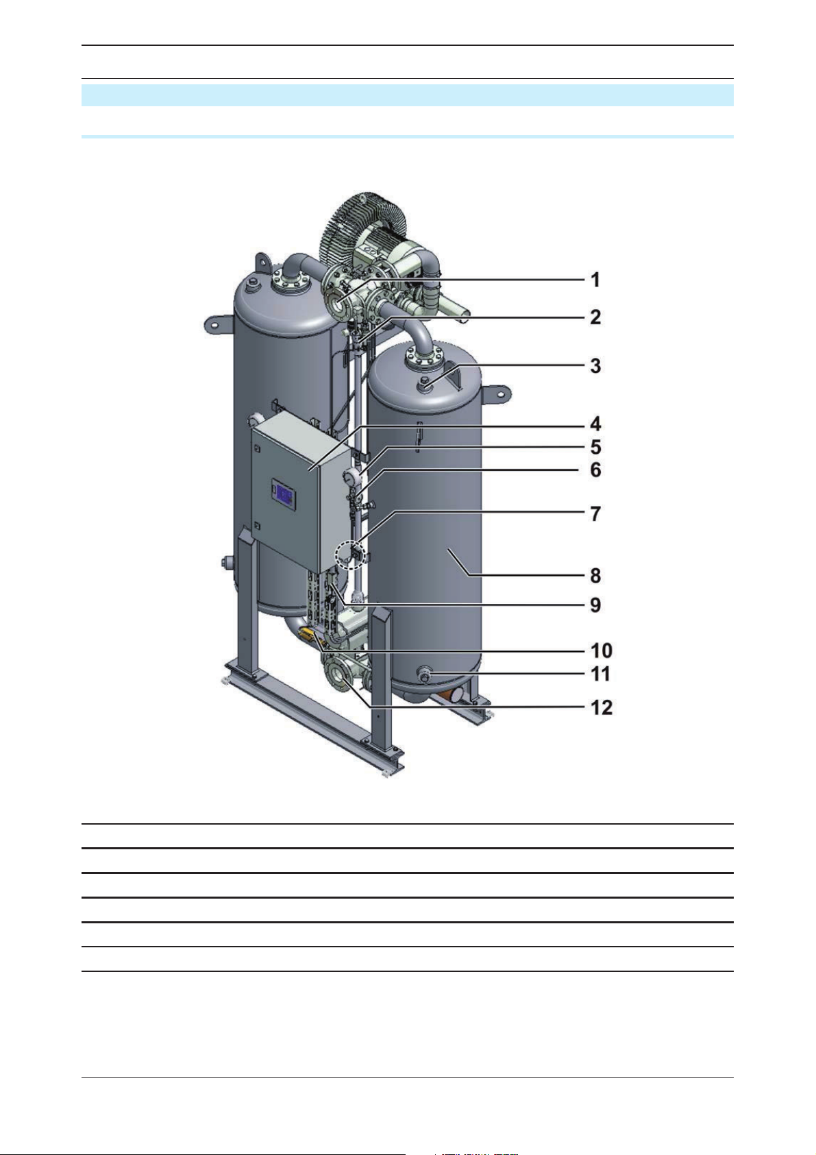
Summary drawing
Front view
1 Main outlet valve l 7 Pressure transducer
2 Control air lter and pressure reducer 8 Vessel
3 Filler sleeve for desiccant 9 Dew point measuring chamber
4 Switch cabinet with operating panel 10 Pressure build-up valve
5 Vessel pressure gauge 11 Discharge sleeve for desiccant
6 Stop valve for vessel pressure gauge 12 Main inlet valve
WVM 40 -1450 13
Page 14
EN | Operating manual Technical product description
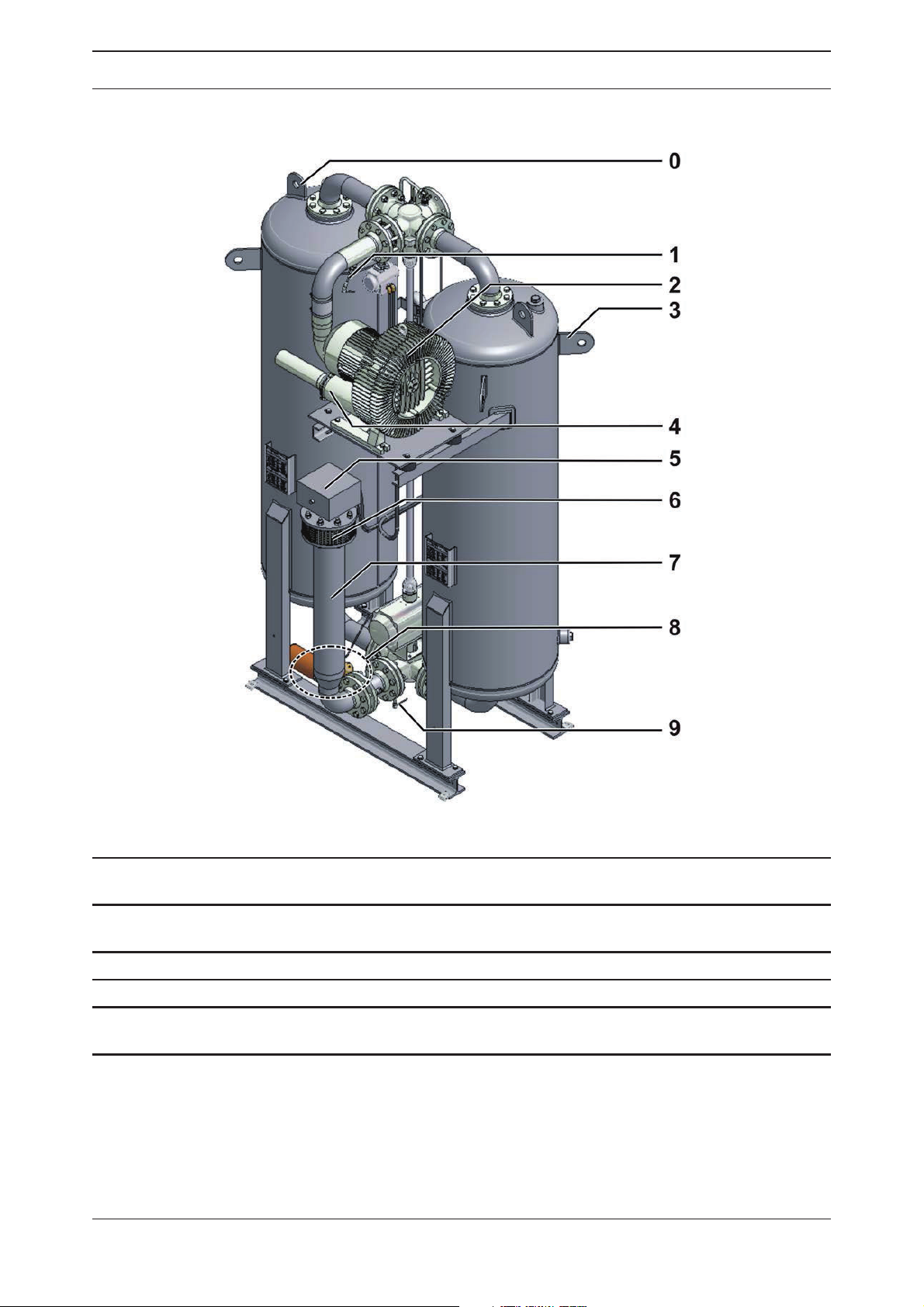
Rear view
0 Lifting eye 5
Resistance thermometer for regeneration
1
gas nal temperature
2 Vacuum pump 7 Heater
3 Lashing eye 8 Expansion valve with silencer
4 Regeneration gas outlet of the vacuum pum 9
Connector box of the heater with release
button for the safety thermostat
6 Suction opening for regeneration gas
Resistance thermometer for the control temperature of the regeneration gas
14 WVM 40 -1450
Page 15
EN | Operating manual Technical product description
Function
The dryer dries the compressed air provided by the compressor and makes it available for
industrial use.
Upstream lters clean the compressed air and remove dust, dirt, oil, and water droplets, before the compressed air reaches the dryer. Thus, an upstream lter is also used for extending
the service life of the drying agent.
Downstream lters clean the compressed air from drying agent abrasions, before it is fed into
the compressed air system.
The two vessels contain an extremely porous drying agent by means of which humidity is
removed from the compressed air and stored just as in a sponge. The stored humidity is then
removed again from the drying agent and re-introduced into the ambient environment.
To this end, the two vessels alternate between different operating modes. Whilst in one vessel, compressed air is de-humidi ed (adsorption), in the other vessel the humid drying agent
is prepared for another charge (regeneration).
These two states, which run in parallel during compressed air preparation, are described
below.
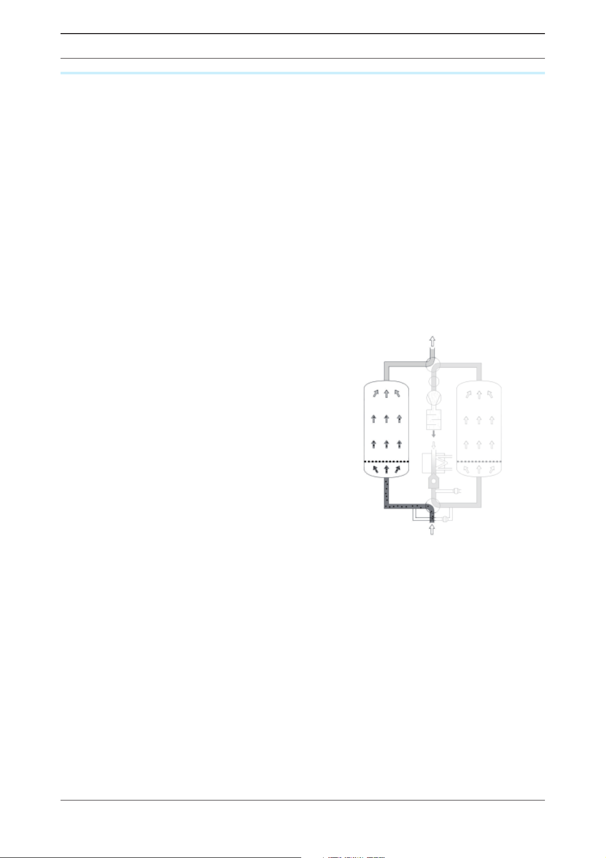
Adsorption
The humid air is supplied through a compressor and the inlet valve of the dryer. The compressed air is then transferred upwards through
the pressurised vessel, where the water contained in the air is absorbed by the desiccant.
The dried compressed air is subsequently fed
into the pipe system at the top of the dryer.
Adsorption (here: absorption in left vessel)
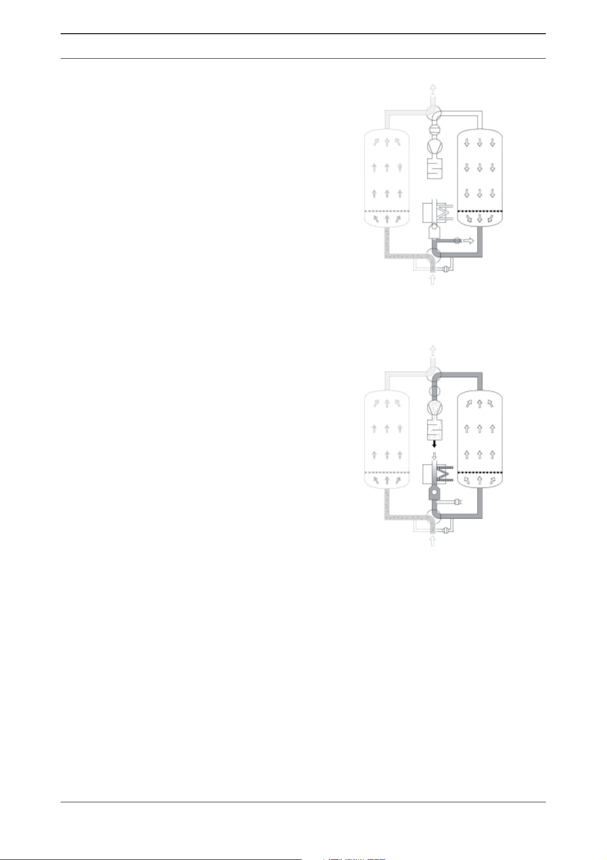
Regeneration (completed in parallel with adsorption)
The regeneration is subdivided into four phases: expansion, heating, cooling and pressure
The following fi gures show the regeneration
phases (here: regeneration in right vessel)
build-up.
With the dewpoint-sensing control option, the
regeneration phase is followed by a standby
phase..
WVM 40 -1450 15
Page 16
EN | Operating manual Technical product description
Expansion phase (duration: some minutes)
The pressure in the right vessel is released
through the expansion valve until the ambient
pressure is reached. The escaping of the compressed air is thereby audible at the silencer as
a low hum.
Expansion phase
Heating phase (duration: several hours)
A vacuum pump sucks ambient air through the
heater* to the vessel to be regenerated. The
air is thereby heated by the heater. The warm
air subsequently ows through the humid
desiccant, removing the water contained in the
agent, which is fed out in the form of steam
together with the air through the piping.
* This can be either a steam or an electrical
heater, but also a combination of both heater
types
Heating phase
16 WVM 40 -1450
Page 17

EN | Operating manual Technical product description
Cooling phase (duration: approx. one hour)
The hot, dried desiccant must now be cooled
and is then ready for absorption. The heater is
switched off so that the vacuum pump feeds
cold ambient air through the vessel.
If the “loop regeneration” option has been
installed, the regeneration air ows in a closed
circuit. Heat dissipation occurs via a water
cooled heat exchanger.
Advantage: No desiccant preloading with
ambient moisture.
Cooling phase
Pressure build-up phase (duration: several minutes)
After completion of the cooling phase, the
pressure in the vessel is raised to operating
pressure via the pressure build-up line.The
vessel can now be switched from regeneration
to absorption operation.
Stand-by-phase (for dewpoint measurement
option)
The regenerated vessel remains in the standby phase as long as the pressure dewpoint is
better than the set switch over value. Switch
over only occurs when the switch over value is
reached or after a maximum cycle duration of
48 hours.
Pressure build-up
Switching over
In the fi xed cycle
A switch-over between the vessels occurs after 6 hours. After switching over, the process
described above is repeated whereby adsorption and regeneration is performed in the other
vessel respectively.
In the variable cycle
The pressure dewpoint-dependent controller lets you operate the dryer in the xed or variable cycle.
In the variable cycle, switchover occurs in dependence of the measured pressure dewpoint.
WVM 40 -1450 17
Page 18

EN | Operating manual Options
Options
The following options are available
◊ Pressure dewpoint control
◊ Insulation and protection against contact
◊ Adaptation for outdoor installation
◊ Auxiliary heating system, anti-freeze protection
◊ Intake socket for regeneration air
◊ Intake lter for regeneration air
◊ Loop regeneration (loop cooler)
◊ Steam heat exchanger instead of electric heater
◊ Steam/electric heater combination
◊ Paint compatible variant
Pressure Dewpoint control
A pressure dewpoint control lets you also operate the dryer in a variable cycle. In the xed
cycle, switchover is effected after a xed time period (usually after 6 hours). In the variable
cycle, the switchover is effected in relation to the dew point reached and the charging of the
drying agent . The adsorption time in the variable cycle amounts to 24 hours maximum.
Insulation and protection against contact
By insulating the dryer, its energy consumption during the heating phase of the regeneration can be considerably reduced. Insulation is mandatory in order to reach deep pressure
dewpoints and if the dryer is subject to frequent change of air (wind, draught, etc.) at the
installation site.
The following components should be insulated::
◊ The vessels of the dryer
◊ The heater
Adaptation for outdoor installation
The standard dryer is designed for installation in con ned places and not for outdoor operation because the following factors affect its function and service life:
◊ Humidity from rain (or other precipitation)
◊ Corrosion due to high humidity or salt content in the ambient air
◊ Freezing of valves, taps, aps and other components at low temperatures.
If you intend to install the dryer outside your premises, always consult the manufacturer prior
to installation in order to agree on special design measures as regards the equipment and the
site where you wish to install the dyer.
Auxiliary heating system / anti-freeze protection
For installation at locations where temperatures below +1 ºC are to be expected, the air
inlet piping of the dryer (or the inlet piping to the preliminary lter system, if any) must be
equipped with an auxiliary heating system in order to prevent the freezing of valves, taps,
aps and other components.
A planned frost-proof variant must therefore be always discussed with the manufacturer in
order to be able to implement speci c design features.
Intake socket for regeneration air
A supply air duct or a supplying pipe can be anged to the dryer by way of the intake socket
to guide regeneration air to the dryer (see page 21).
Intake fi lter for regeneration air
The intake lter removes solid impurities (e.g. dust) from the regeneration air before it reaches
the dryer.
18 WVM 40 -1450
Page 19

EN | Operating manual Options
The intake lter is ange mounted and can therefore only be installed in conjunction with a
intake socket (see before).
Loop regeneration (loop cooler)
The desiccant absorbs the moisture in the ambient air during the cooling phase. The amount
of moisture taken in can be accordingly high at very high ambient temperatures and relative
humidity (e.g. in tropical operating environments).
A loop cooler can be implemented in order to prevent this situation and to ensure a stable
pressure dewpoint under above mentioned adverse circumstances. This principle implies
taking in the regeneration air only once and then circulating it. The heat dissipates via a water
cooled heat exchanger.
The operator must provide a cooling water connection and appropriate cooling water valves.
Note:
The heat exchanger choice depends on the quality of the cooling water. For this
purpose, you should contact the dryer manufacturer beforehand.
Steam heat exchanger
To heat the regeneration air, a steam heat exchanger can also be used as an alternative to
the standard electric heater. The steam heat exchanger comes with an appropriate steam
shut-off valve.
In this case, the scope of delivery can also comprise supplementary documents such as data
sheets or supplementary operating manuals.
Steam/electric heater combination
In this option, the existing electric heater is supplemented by an additional steam heat exchanger. This allows for three operating modes:
Pure steam operation
Suf cient hot steam is available for regeneration. The electric heater is not needed.
Pure electric operation
Hot steam is not available, the electric heater performs all the heating.
Combination operation
The heating capacity of the steam heat exchanger is not suf cient to reach the required
regeneration temperature. As a consequence, the electric heater is turned on to compensate
for the temperature de cit.
Paint compatible variant
Paint nishing systems make great demands on the compressed air purity because even the
tiniest impurity can degrade the paint quality. Diminutive amounts of foreign particles containing oil and grease or solvents — in particular silicones — can result in craters, discolourations, swells or other paint impurities.
Paint compatible dryers are equipped with seals and lters that are absolutely free of grease
and silicone and thus ensure a high compressed air quality for painting.
WVM 40 -1450 19
Page 20

EN | Operating manual Transportation, installation and storage
Transportation, installation and storage
Danger due to incorrect transportation!
The dryer must be transported by authorized and qualifi ed specialist personnel
only. During transportation all applicable national regulations for accident prevention must be complied with. Otherwise there is a risk of personal injury.
Warning!
Risk of damaging the dryer when lifting it at the lashing eyes. The lashing eyes
laterally fastened to the vessels are not intended to safely bear the dryer‘s
weight.
The dryer and in particular the vessels could be damaged.
Always use the lifting eyes at the vessel top to lift the dryer.
Note:
The dryer is equipped with lashing eyes fastened to the vessel sides. Use these
eyes to secure the unit during transport.
◊ Only use suitable and technically perfect lifting gear with a suf cient carrying capacity.
◊ During transportation the dryer must be carefully secured against falling over.
◊ Remove the transport packaging at the installation site only and dispose of it in a proper
manner.
The manufacturer will not be liable for any damage caused by incorrect storage or incorrect
transportation. Please note therefore the following instructions as well as the storage instructions on page 24.
What to do in the case of transport damage occurring?
Check whether only the packaging or the dryer itself were damaged.
Inform the haulier immediately in writing of any damages.
Contact the manufacturer urgently in order to report the damage. You will nd the tele-
phone number on page 6.
Warning!
A damaged dryer must not be taken into operation! Damaged components may
lead to functional faults and possibly cause further damage.
20 WVM 40 -1450
Page 21

EN | Operating manual Transportation, installation and storage
Transporting dryer to its location of installation
Requirements regarding the location of installation
The general conditions at the site of installation greatly affect the operation of the dryer and
the service life of the desiccant. In order to ensure long-lasting operation with minimum maintenance, the location of installation must meet the following requirements:
Weather protection
◊ The location for installation must be weatherproof and inside a building. Protect the dryer
against moisture. Read the notes on page 18 when the dryer is to be installed outside
(option). When installed outside, the dryer must be insulated.
Ambient air
◊ The ambient air must be as free from dust as possible since heavily dust-laden installation
locations reduce the drying agent’s service life. In case of doubt we recommend to supply
the dryer with regeneration gas by way of supply ducts or pipes. For this purpose, a special
heating pipe or a heating pipe adapter can be used for retro tting
Ambient temperature:
◊ The ambient temperature must not be below +1° C. Implement an additional heating if nec-
essary (see page 18). In this context please also heed the information regarding insulation
on the following page.
◊ If possible, the ambient temperature should not exceed 30° C and the relative humidity not
exceed 60% in order to ensure suf ciently effective regeneration and a suitable pressure
dew point. A higher ambient temperature or relative humidity must be specially considered
when designing the dryer and recorded in the offer document if this proves to be unfeasible.
If the required cooling water is available, you should implement the optional loop cooler.
◊ Please also heed the appropriate notes in section Technical data!
Ventilation
◊ Provide suf cient ventilation as moisture is released to the ambient air during regeneration.
Note:
Guide the regenera¬tion gas from the vacuum pump out of the installation
room using exhaust ducts or pipes. Please follow the notes on page 26 regarding the installation of the supply line.
Criteria for insulation
The dryer must be insulated if one or all of the following criteria are met:
◊ When the room temperature at the installation location drops below 10° C for more than 1
hour per day.
◊ When the room temperature at the installation location drops below 15° C for more than 3
hours per day.
◊ In case of draught at the installation location as can be expected with ventilation systems,
passages or similar. This applies regardless of the room temperature. Measure the draught
ow rate in the vicinity of the dryer when you are in doubt. Insulate the dryer if the ow rate
exceeds 0.3 m/s in the immediate vicinity of the dryer.
◊ When a pressure dew point exceeding –40° C is to be supplied.
The dryer can rst be delivered without insulation. Retro t an insulation if the desired pressure dew point cannot be attained due to the above criteria
Noise emission
Heed the dryer’s noise emission when selecting the installation location
WVM 40 -1450 21
Page 22
EN | Operating manual Transportation, installation and storage
Installation base
The installation base must be level, solid and free from vibration. It must be capable of bearing the dryer’s weight. You will nd the dryer’s weight in the technical data in the appendix.
Please add another 10% to the dryer’s weight in your calculations. This will ensure the moisture trapped by the desiccant later is accounted for.
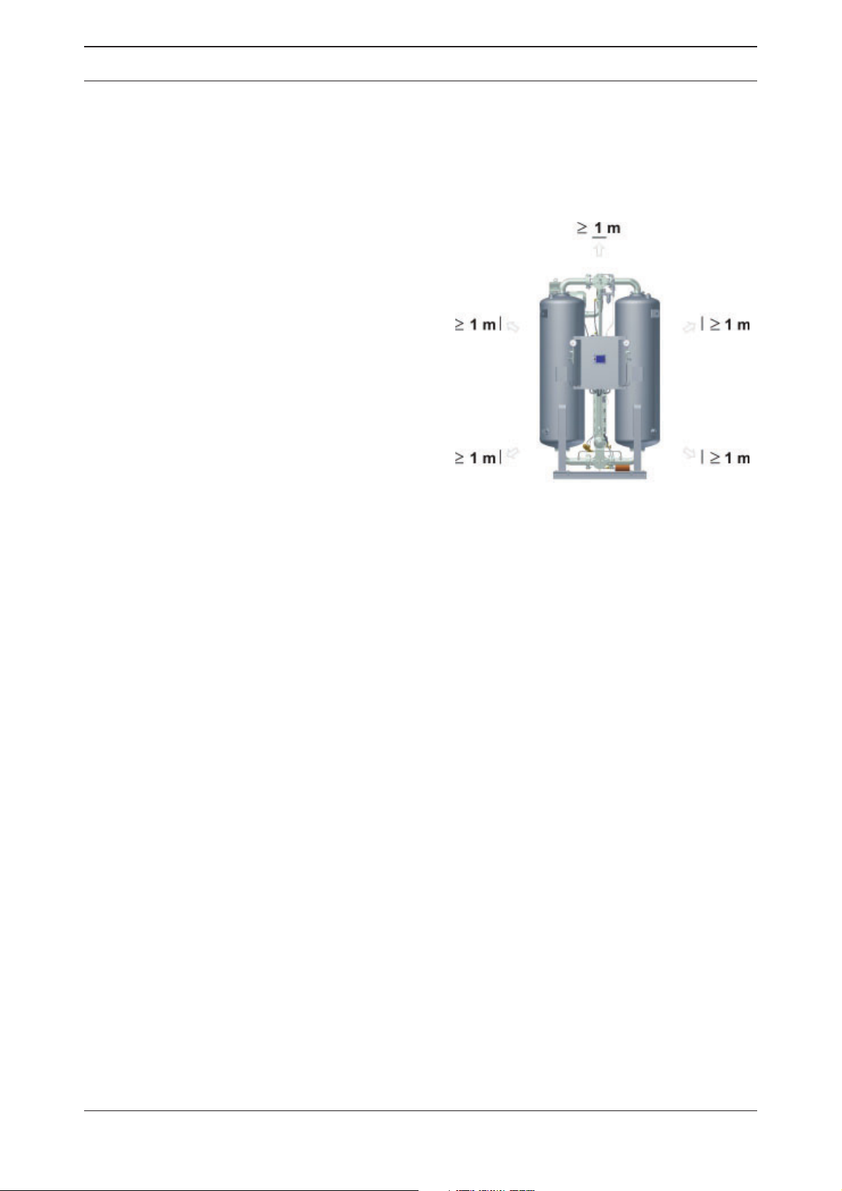
Lateral clearances
The dryer should be erected with suf cient
clearance above, to the sides and behind so
that maintenance work can be carried out
and the drying agent can be changed without
hindrance (see illustration).
Lifting devices
You should have lifting devices with an adequate load capacity available for assembling
and maintaining individual parts such as the
vacuum pump.
Required clearances at the top
and the sides of the unit = minimum 1 m
If in doubt, contact a specialised technician to carry out a site inspection. If you have any
queries in relation to the location of installation, please contact our customer service department or our sales team.
22 WVM 40 -1450
Page 23
EN | Operating manual Transportation, installation and storage
Transporting of dryer
Risk of serious injury due to improper transport!
The dryer may only be transported by authorised and suitably qualifi ed technical personnel. During transport, always comply with the applicable statutory
safety regulations . Otherwise, there is a risk of serious injury.
Warning!
Risk of damaging the dryer when lifting it at the lashing eyes. The lashing eyes
laterally fastened to the vessels are not intended to safely bear the dryer‘s
weight.
The dryer and in particular the vessels could be damaged.
Always use the lifting eyes at the vessel top to lift the dryer.
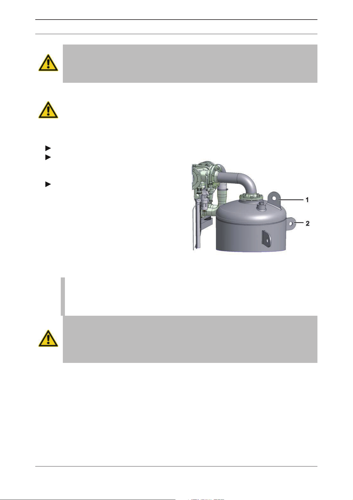
Remove packaging.
Attach suitable lifting gear to the lifting
eyes on the vessels (see Item 1 on the adjacent
illustration)..
The lashing eyes (Item 2) are intended to
secure the unit during transport and are not
suited to lift the dryer.
Lifting and lashing eyes at vessel
Note:
The vessels are fi lled with layers of various desiccants. They should therefore
be transported in an upright position in order to prevent the mixing of these
desiccants, as this could impair the operation of the dryer.
Risk of tilting!
The dryer should only be transported in an upright position. However, this means that the centre of gravity of the unit is located in the upper half of the dryer,
so that there is a serious risk that the unit might tilt over.
Therefore, adhere to the transport instructions outlined below.
WVM 40 -1450 23
Page 24
EN | Operating manual Transportation, installation and storage
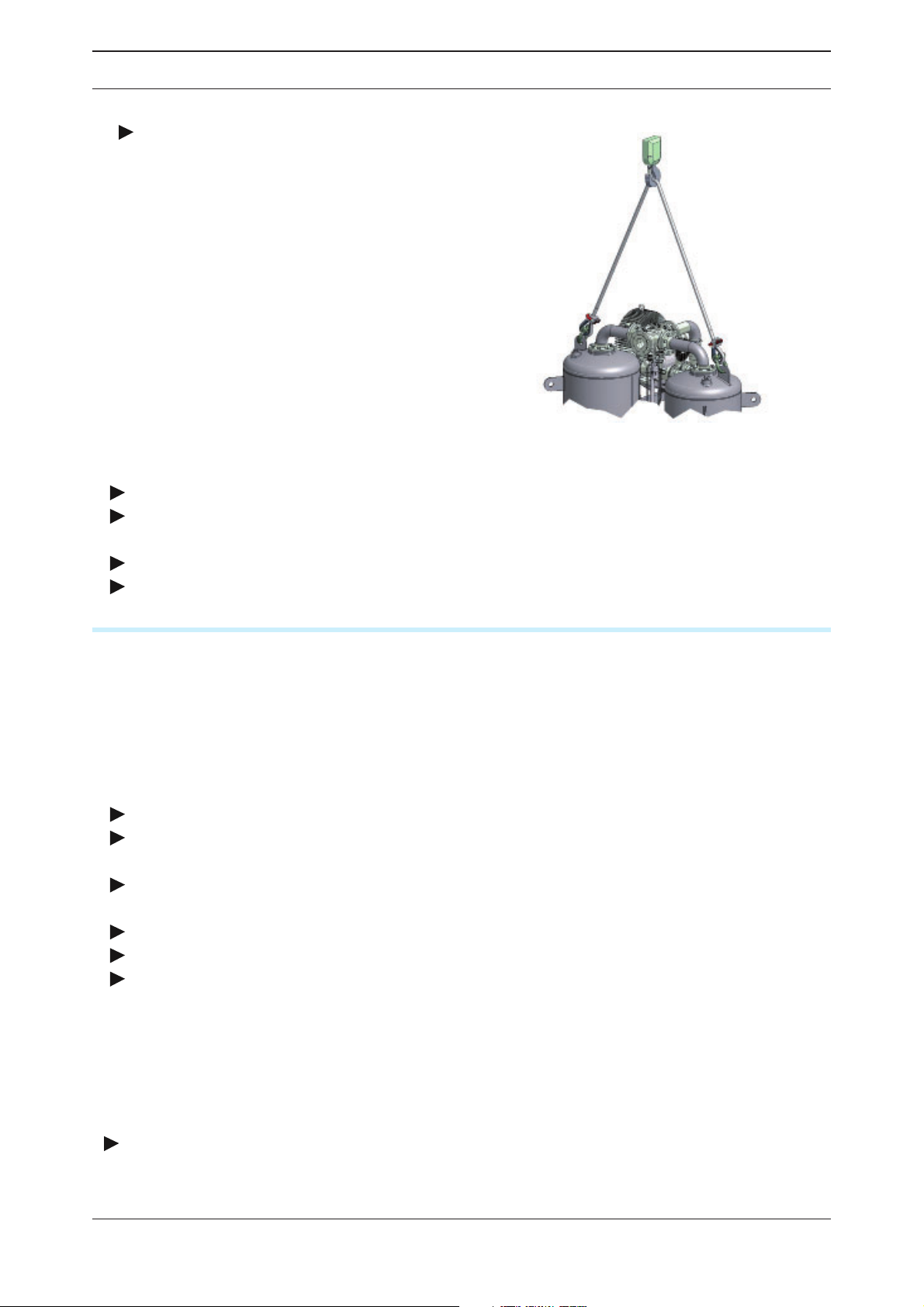
Transport by crane
Transport the adsorption dryer in an upright
position to its location of installation.
Transport by crane
Transport by forklift
When using a forklift, ensure that the dryer is always in an upright position.
Secure the dryer with screws to a pallet to ensure that it cannot tilt or fall from the forklift.
Installation and anchoring of the dryer
Secure dryer by means of suitable securing devices to the oor.
On oscillating oors: The dryer must be positioned on suitable oscillation absorbers.
Storage
If the dryer is not to be installed immediately after delivery, it must be stored at a suitable
location that ful ls the following requirements:
◊ The dryer must not be stored outdoors.
◊ The storage room has to be dry.
◊ The storage room must be free of dust; otherwise, cover dryer with a tarpaulin.
◊ The ambient temperature in the storage room may not be below +1 ºC
To storage the dryer, proceed as follows:
Decommission dryer as described on page 36.
Ensure that the inlet valve and the outlet valve installed on the site are closed and release
all pressure from the dryer.
Make sure that existing steam valves (with optional steam heat exchanger) or cooling
water valves (with optional loop regeneration) are closed.
Disconnect dryer from compressed air system.
Disconnect the plant from the electric mains supply and any external and supply lines.
Cover the following inlet and outlet openings with lm or similar material to protect them
against contamination by dust and dirt:
— inlet and outlet openings for compressed air
— inlet for the regeneration gas at the heater
— regeneration gas outlet at the vacuum pump
— cooling water intake and exit (with optional loop regeneration)
— hot steam intake (with optional steam heat exchanger)
Cover the dryer with a tarpaulin, if possible..
The dryer is not suitably prepared for prolonged storage.
24 WVM 40 -1450
Page 25

EN | Operating manual Transportation, installation and storage
Note:
To recommission the dryer after prolonged storage, please proceed as described for initial commissioning (see page 31).
Store drying agents
Do not store drying agents in the open air.
Protect drying agents against humidity.
WVM 40 -1450 25
Page 26

EN | Operating manual Installation
Installation
Only authorized and qualifi ed specialist personnel may carry out work on pipes
and electrical systems.
The electropneumatic switch cabinet in particular must be opened and serviced by an instructed trained electrician only
As soon as the dryer has been set up at its installation location, you can install the com-
pressed air infeed and outlet lines and make the electrical connections.
Requirements for installation
Risk of damage resulting from exceeding the limit values!
A safety device protecting against exceedance of the maximum permissible
operating gauge pressure must be present.
The safety device must be installed so that the dryer is reliably protected from
exceeding the maximum permitted operating pressure even when the temperature of the compressed gas increases.
Warning!
Safe dryer operation cannot be ensured if the requirements described here are
not met. This can also degrade the dryer’s function.
For proper installation, the operator must provide the following:
◊ Connections and lines must be provided for compressed air intake and exit.
◊ The operator must install shut-off valves for compressed air and supply media at the
intakes and exits.
◊ All pipelines, couplings and connections must have the correct diameter and be matched to
the operating pressure.
If the regenerated gas is supplied to and led away from the dryer by ducts or pipelines installed by the operator, the following instructions must be adhered to:
Avoid any loss of pressure!
A pressure loss in the air inlet and outlet pipelines >20 mbar may signifi cantly
affect the dryer’s functionality. The consequences may include the following:
— Failure to reach the pressure dewpoint
— The dessicant will become unusable well before expiry of its normal
useful life
It is therefore vital to observe the following points:
— Do not allow the maximum pressure loss in the air inlet and outlet pipelines to exceed 20 mbar (e.g. maximum 10 m pipline with three bends)!
26 WVM 40 -1450
Page 27
EN | Operating manual Installation
— The selected diameter of the air inlet and outlet pipelines must be at
least two nominal widths greater than that specifi ed by the connection fl ange
on the vacuum pump!
— In order to prevent corrosion in the pipes, we recommend the use of galvanised or
stainless steel piping.
— Provide a supporting fan in case of longer or widely branched pipelines and high
differential pressures. Please contact the manufacturer for more information.
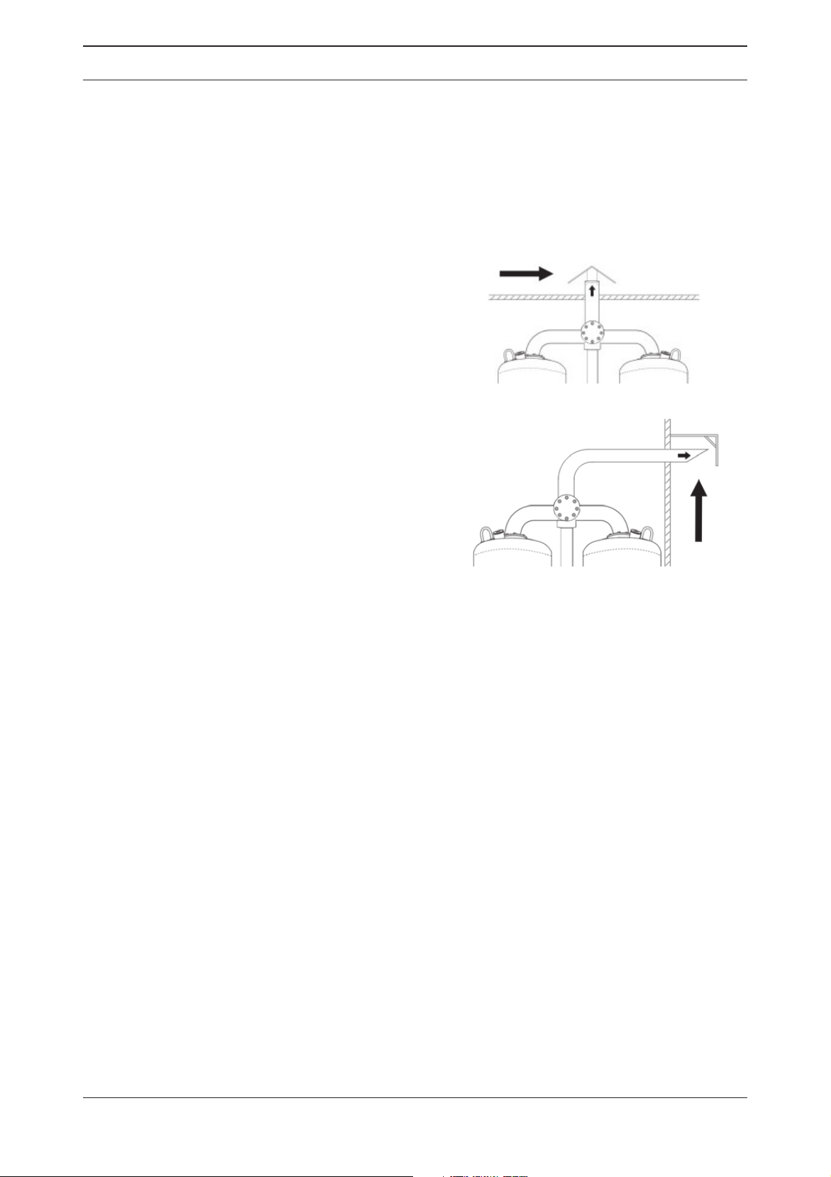
— The exit point of lines must be protec-
ted with a rainguard to prevent water from
reaching the dryer inside (see gure).
— if necessary, the exit point of lines
should be barred with grilles in order to prevent foreign objects or animals from entering
the dryer.
— The outlet line must be installed in such
Rainguard when lines point upwards
a way that there is no risk of injury from hot
regeneration gas.
Rainguard when line exits to the side
— If both an inlet and an outlet line are installed, ensure that the escaping hot regener-
ation gas is not again drawn into the inlet line. The outlet opening of the outlet line should
thus be positioned higher than the inlet opening.
— If both an inlet and an outlet line are installed, ensure that condensation water cannot
drop from the outgoing line onto the supply air intake when installing supply as well as out-
going lines. For this purpose, the outlet line should be routed farther to the outside than the
inlet line.
— Route the supply line at suf cient height to prevent taking in coarse dirt or other detri-
mental foreign objects.
WVM 40 -1450 27
Page 28
EN | Operating manual Installation
Installation of pipelines
To ensure proper operation of the dryer, its connection to the compressed air system must be
free from stress.
Prior to installation, check all incoming and outgoing compressed air lines and valves for
damage or contamination.
Inspect screw connections and retighten, if necessary (screw connections might become
loose during transport).
Ensure that the pipelines are not under any stress when installed!
Stress on pipes might result in the rupturing of the lines during operation, resulting in damage to persons and property.
Connect the dryer to the compressed air system, while heeding rated diameter and
pressure.
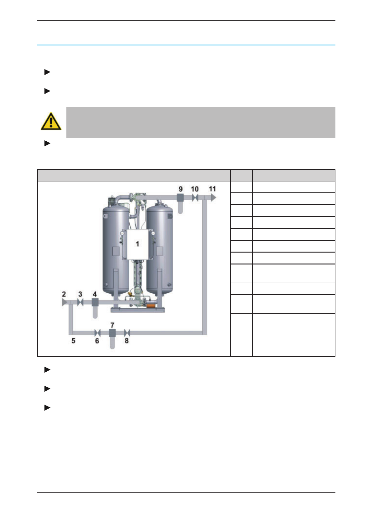
The gure below shows a proper installation.
Compressed air system Item Component
1
2
3
4
5
6
7
8
9
10
11
Dryer
Humid air inlet
Compressed air inlet valve
Preliminary lter
Bypass line
Valve in bypass line
Bypass lter
Valve at outlet of bypass
lter
After lter
Compressed air outlet
valve
Dry air outlet
Example of a proper installation with bypass line
The connecting lines of the preliminary lter (4) should be at a slight slope towards the
lter.
A shut-off valve (3, 10) at both the inlet and outlet for the compressed air must be installed.
In units with bypass line (5) and additional shut-off valve:
Ensure that the line is installed in such a way that the compressed air ow must not be interrupted during maintenance of the dryer.
28 WVM 40 -1450
Page 29
EN | Operating manual Installation
Connection of electrical components
Beware of electrical voltage!
Work on the electrical system must be entrusted to instructed, authorised electricians only. The electropneumatic switch cabinet in particular must be opened
and serviced by an instructed trained electrician only.
Connection to power supply
The dryer components have been connected in the switch cabinet at the factory. You only
need connect it to the electric supply.
Make sure the cross section of the electric cable matches the dryer’s power consumption
and the voltage available at the customer’s.
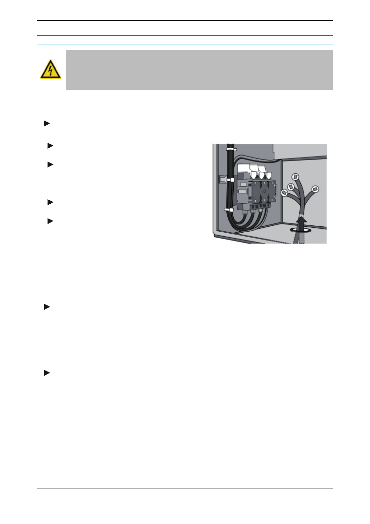
Insert power cable through the left recess
at the base of the switch cabinet (see gure).
Connect wires according to the circuit
diagram to terminals L1–L3 at the terminal
strip (the circuit diagram is attached inside the
switch cabinet).
Connect the dryer‘s earth cable to the PE
terminal.
Protect the dryer against short circuits by
installing fuses to all phases.
Cable recess in switch cabinet base and
terminal connections for power supply
Connection of dryer to the fault signalling system
There is an ex-works option to connect the dryer to a fault signalling system. With such a
system, faults occurring anywhere in the dryer unit can be displayed at one location, e.g. at a
control station.
Connect the cables of the fault signalling system to the terminal strip as show in the
circuit diagram .
External interfaces
The dryer controller features interfaces for data transmission.
Please heed the controller manual for more information on these interfaces.
Check bolt connections
Before the initial start-up:
Check all unions and bolt connections as well as the terminals in the control cabinet for
secure seating; re-tighten if necessary.
WVM 40 -1450 29
Page 30

EN | Operating manual Start-up
Start-up
Warning!
The dryer must be taken into operation by trained personnel only! Untrained
personnel does not have the required knowledge. Such personnel might cause
serious faults.
Note:
You can order the initial commissioning and start-up from the manufacturer
and have your personnel trained by the manufacturer. For telephone number,
see page 6.
◊ Carry out all prescribed tests and checks.
◊ Before start-up, ensure that no tools or other foreign parts have been left lying in a part of
the dryer where they might pose a hazard to the dryer being started up.
Requirements for initial commissioning
The following conditions must be met for initial commissioning:
◊ All pipelines are free of contamination.
◊ All shut-off valves are closed.
◊ The dryer has been properly set up, wired and connected.
◊ The compressors are ready for operation.
◊ At the outlet side, a compressed air consumer is present, i.e. compressed air can ow
through the dryer.
◊ Operators for the components are available.
Inspection to be carried out prior to commissioning
◊ all pipe, cable and screw connections have been retightened,
◊ none of the lines are worn at edge of the dryer body,
◊ all connections are properly secured,
◊ the electric connections are properly secured and in good condition,
◊ the operator-supplied components such as safety valves and other equipment holding
pressure are not blocked by dirt or paint,
◊ all components of the compressed air system that are under pressure (valves, hoses, etc.)
are free of wear or other defects,
◊ suf cient amounts of required supply media such as steam or cooling water are available at
suitable quality and the respective shut-off valves are open.
Overview of the operating and display elements
The operating panel at the switch cabinet door allows for the monitoring of the operating statuses and for the modi cation of settings. The display is a Touch Screen Panel. To operate,
touch the elements on the screen.
For further information on the operating panel and the controller’s functions, please refer to
the enclosed controller manual.
30 WVM 40 -1450
Page 31
EN | Operating manual Start-up
Vessel pressure gauge
On both vessels, pressure gauges are tted which show the operating overpressure. The
operating overpressure indicates the operating phase of the relevant vessel:
◊ During adsorption the pressure gauge should indicate the nominal operating overpressure.
◊ During regeneration the indication of the pressure gauge on the regenerating vessel
— must drop from the operating gauge pressure to < 0.5 bar gauge pressure during the
expansion phase,
— must indicate a vacuum of 50 – 100 mbar during the drying phase.
◊ During the pressure build-up phase the indication on the pressure gauge should again rise
to operating overpressure level (both vessel gauges indicate the same operating pressure).
Commissioning of the dryer
Risk of injury from escaping hot regeneration gas!
Hot humid air might escape from the the regeneration gas outlet at the vacuum
pump. Therefore, keep clear of the blow-off outlet during operation of the unit.
Risk of injury from crushing!
During the switching from adsorption to regeneration, there is a risk of injury
from crushing at the universal shaft and the drives. During switching, stay clear
of these components!
Risk of injury from hot surfaces!
During operation, certain surfaces of the dryer are heated to temperatures of
over 120 °C. At insulated dryers, screw connections might protrude from the
insulation. Do not touch hot surfaces. Allow surfaces to cool before you carry
out any work at the dryer.
Risk of injury from suddenly escaping gas!
While the unit is under pressure, never remove any components or otherwise
interfere with the dryer! Suddenly escaping gases can lead to serious injury!
Prior to any work, release all pressure from the unit.
◊ Operate the dryer only within the permitted limits. Operation of the dryer under conditions
for which it is not designed may lead to malfunctions.
◊ On no account should the factory settings of the control programme and the frequency
converter be altered without consulting the manufacturer.
◊ The higher the capacity of the dryer, the more noise it produces during operation. The oper-
ator must therefore provide suitable protective equipment (e.g. earmuffs).
◊ Depending on the size of the dryer, the compressed air network and the respective legal
requirements in your country, it may be necessary to perform initialisation according to the
directive for pressure equipment.
◊ Check the dryer for visible damage and faults at regular intervals. Immediately report
changes, also those regarding operational behaviour, to the institution or person in charge.
In the event of an emergency or if safety-relevant malfunctions are observed, immediately
switch off the dryer. The dryer may only be restarted after the malfunction has been eliminated.
WVM 40 -1450 31
Page 32
EN | Operating manual Start-up
Preparation for commissioning
For the commissioning of the dryer, follow the instructions as set out below.
Pressurisation of unit
Check the stop valves at the vessel pressure gauges to ensure that they are opened (see
page 13).
Check the valves at the inlet and outlet for the compressed air (provided by operator) and
ensure that they are closed (see also example of installation on page 28).
Ensure that the compressed air system in front of the dryer is pressurised. Adjust pres-
sure, if necessary. Switch on compressor.
Slowly open compressed air inlet valve!
Avoid abrupt pressure increase! Rapid pressurisation may lead to serious damage to the dryer! Therefore, open compressed air inlet valve slowly and with
caution!
Slowly open compressed air inlet valve
leading to the dryer.
Monitor the pressure increase at the vessel
pressure gauge (see page 13): In one of the
vessels, the pressure must be increased until it
reaches the operating pressure.
Compressed air inlet to the dryer
Avoid abrupt pressure drop!
Avoid abrupt pressure drops by all means! Too fast a pressure drop or too high
fl ow rates can cause damage to the dryer. For this reason, make sure to open
the pressure outlet valve only slowly or implement a start device in the compressed air network immediately downstream of the dryer!
Slowly open compressed air outlet valve. Monitor the pressure in the pressurised vessel
at the vessel pressure gauge (see page 13). The vessel pressure should not drop by more
than 25 % and must never drop below the minimum pressure of the installed valves (approx.
5 bar).
Note:
You may only switch on the dryer when the pressure gauge at the pressurised
vessel indicates the required minimum pressure for the installed valves (see
above).
The unit is now fully pressurised. Proceed by checking the direction of rotation of the vacuum
pump.
32 WVM 40 -1450
Page 33
EN | Operating manual Start-up
Inspecting direction of rotation of the vacuum pump
Note:
For the next steps, you will need an assistant.
Ensure that the main switch is in position „0“
Open switch cabinet door.
Remove fuses of the heater (for location of the fuses see electrical diagram). This is
necessary to ensure that the heater is not inadvertently switched on and thereby damaged.
Set main switch to position „I“.
Start the dryer (see the operating manual for the controller).
After the expansion time has expired, the regeneration valve opens and the vacuum
pump starts running.
Caution!
If an error is shown, fi rst eliminate the cause of the error, and only then continue with the commissioning.
The assistant must position himself in a location from where can look on the fan wheel of
the vacuum pump motor.
The correct direction of rotation of the vacuum pump is indicated by an arrow on the pump
housing. The arrow is painted in the colour of the housing and extends over several cooling
ns.
Wait until the vacuum pump is fully started. Then stop the dryer. The fan wheel continues
rotating for a short period of time
During this time, the assistant must check, whether the wheel rotates in the correct
direction..
The vacuum pump direction is correct, if the fan wheel rotates in the direction of the arrow.
Procedure if direction of rotation of the vacuum pump is correct
Set main switch to position „0“.
Insert heater fuses.
Procedure if direction of rotation of the vacuum pump is not correct
Even short-term operation of the dryer with incorrect direction of rotation of the vacuum
pump might lead to damage to the heater. Therefore, always correct pump direction, if necessary.
Set main switch to position “0”.
Disconnect dryer from power supply.
Caution! Risk of electrocution!
Prior to adjusting direction of rotation, disconnect the unit from the power
supply. Otherwise, there is a risk of serious injury from live cables and components!
Exchange cables L1 and L2 at the terminals.
Check direction of rotation of the vacuum pump.
Insert heater fuses.
Proceed with starting the dryer
WVM 40 -1450 33
Page 34
EN | Operating manual Start-up
Note:
Checking can be facilitated for vacuum pumps starting up immediately (i.e.
without star-delta circuit, see circuit diagram in the Appendix):
Remove fuses of the heater.
Turn on main switch.
Briefl y actuate the contactor for the pump (see circuit diagram), e.g. with a
screwdriver.
Check and if necessary correct the direction of rotation (see above).
Commissioning of dryer
Set main switch to position “I”
Start dryer (see the operating manual for the controller).
The unit is now fully switched on, provided that no error message is displaye
How to proceed if an error message is displayed
Warning!
In an emergency and in the event of safety related faults (e. g. a sudden escape
of compressed air, defective components) take the plant out of operation immediately as described on page 36.
Stop the dryer.
Set main switch to position “0”.
Eliminate the error. (heed the malfunction table in the controller manual).
Repeat commissioning.
34 WVM 40 -1450
Page 35

EN | Operating manual Monitoring dryer operation
Monitoring dryer operation
Notes on specifi c operating situations
Parallel operation of several plants
The standard con guration comprises one compressor and one dryer. Please contact the
manufacturer if you plan a plant differing from this con guration.
Part-load dryer operation
The dryer provides optimum performance at high loads. This is the case if the operating
parameters match or slightly fall below the speci ed values.
Dryer performance can degrade if the dryer often operates at part-load. Dryer performance
increases as soon as the load is raised.
Part-load operation can occur
◊ due to too low ow rates (< 30 % of rated value),
◊ by operating the plant with predried air (i.e. the relative humidity of supply compressed air
is below 30% RH),
◊ due to an operating pressure that is higher than the rated pressure,
◊ due to a compressed air temperature that is much lower than the rated temperature,
◊ if several of the above conditions apply.
WVM 40 -1450 35
Page 36

EN | Operating manual Shutdown and restart dryer
Shutdown and restart dryer
In the following cases, the dryer must be fully shut down and depressurised:
◊ In the event of an emergency or malfunction
◊ For maintenance work
◊ For dismantling
Risk of injury from escaping compressed air!
Never remove any parts of the dryer, or manipulate the same in any way, as
long as the unit is pressurised! Suddenly escaping compressed air might cause
serious injuries.
Prior to any work, release all pressure from the unit.
Emergency shutdown
The master switch of the dryer also serves as an emergency stop switch. Proceed as follows
to stop the dryer in an emergency:
Set main switch to position „0“.
Close compressed air outlet valve.
The dryer is now shut down. Restart the dryer only after having eliminated all errors!
Stopping the dryer
Please proceed as follows if no compressed air is needed at night or at weekends:
When the compressor remains on
Close compressed air outlet valve.
Leave the customer‘s intake valve for compressed air open (see installation example on
page 28).
Stop the dryer (see the operating manual for the controller).
The dryer is halted. The current programme is interrupted at a point from where it can be
restarted without dif culty at any time.
When the compressor is switched off
Close compressed air outlet valve.
Close compressed air inlet valve.
Stop the dryer (see the operating manual for the controller).
The dryer is halted. The current programme is interrupted at a point from where it can be
restarted without dif culty at any time.
Note:
It is not necessary to set the main switch to position „0“. The display remains
on.
36 WVM 40 -1450
Page 37

EN | Operating manual Shutdown and restart dryer
Depressurising and shutting down the dryer
You must depressurise the dryer and shut it down for:
◊ maintenance
◊ disassembly
Stop dryer (see the operating manual for the controller).
Depending on the installed controller, the following stop situations can occur:
◊ The dryer completes the current regeneration cycle and pressure build-up before the pro-
gramme stops.
◊ The dryer stops immediately (or after one minute during the heating phase).
Close the pressure inlet valve and the pressure outlet value (both provided by customer).
Close any existing inlet and outlet valves for supply media (e.g. cooling water and steam).
◊ The dryer is separated from the compressed air network and can be shut off now.
Set the master switch to “0”
Note:
Do not let any compressed air fl ow through the dryer after it has been shut
down! The desiccant in one of the vessels will otherwise continue to be loaded
with moisture without the other vessel being regenerated at the same time.
Depressurise the adsorbing vessel (e.g. by opening the manual drain valve on the
downstream lter).
Wait until the pressure on the vessel pressure gauge of the adsorbing vessel has dropped
to 0 bar.
Using the vessel pressure gauge, check whether both vessels have been depressurised.
For maintenance work: wait until the dryer has cooled down.
Risk of injury from hot surfaces!
Certain surfaces at the dryer remain hot even after the unit has been shut
down. Do not touch hot surfaces! Allow surfaces to cool before you carry out
any work at the dryer.
If work is to be carried out on the electrical system
Depressurise and shut down the dryer, following the instructions in the above chapter.
Risk of injury due to voltage-carrying parts!
The electrical supply cable and external power lines are live even after the
dryer is switched off and, in the event of body contact, may cause serious
injury! Before carrying out any work on the electrical system, the electrical
supply cable and all external power lines must be made voltage-free!
Make the electrical supply cable to the dryer voltage-free.
Secure the electrical supply cable to the dryer against switch-on.
WVM 40 -1450 37
Page 38

EN | Operating manual Shutdown and restart dryer
Restart
Restarting dryer: compressed air system and dryer under operating pressure
If the dryer was shut off: switch on the dryer by setting the main switch to I.
Otherwise:
Start the dryer (see the operating manual for the controller).
If necessary, slowly open the compressed air inlet and outlet valves installed by the
operator.
The dryer is now ready for operation and continuous automatic cycle.
If compressed air system and dryer have not remained at operating pressure
If disconnected, reconnect the voltage supply of the dryer.
Pressurise and switch on the dryer as described in the section on page 31.
The dryer is now in operation again and operates fully automatically.
38 WVM 40 -1450
Page 39

EN | Operating manual Maintenance and repair of the dryer
Maintenance and repair of the dryer
In order to allow maintenance work on the dryer to be carried out ef ciently and without danger for maintenance personnel, you should comply with the following instructions.
Notes on maintenance
Warning!
Maintenance tasks may be carried out only by authorized and qualifi ed specialist personnel, and only with the plant in a switched off and depressurised
condition.
Note:
In order to ensure perfect maintenance and reliable operation we recommend
that you conclude a maintenance contract (For telephone number, see page 6).
When exchange or replacement parts are ordered, always state the dryer type
and the build no. of the dryer. These data are found on the type plate attached
to the control cabinet door.
◊ Carry out all maintenance work only when the plant has been shut down and depressur-
ised!
◊ Bolt connections must be undone with care! Note ram pressure values! Otherwise emerging
media may cause personal injury.
◊ Do not modify the factory settings of the control system in any way without prior consulta-
tion with the manufacturer.
◊ Never carry out welding work on a vessel or modify the same in any way!
◊ Following maintenance work, always check all ange and bolt connections for leakage and
secure seating.
◊ Never use pipes and ttings as steps or holding points! The components might fracture, or
the distortions which occur may cause internal damage on the dryer. There is a risk of injury
by slipping off the components, components breaking off, and expanding compressed air!
◊ Never leave tools, loose parts or cloths in, at or on the dryer.
◊ Only use replacement parts that are suitable for the relevant function and meet the techni-
cal requirements stipulated by the manufacturer. This is always the case, if you use original
replacement parts only.
WVM 40 -1450 39
Page 40
EN | Operating manual Maintenance and repair of the dryer
Regular maintenance taskse
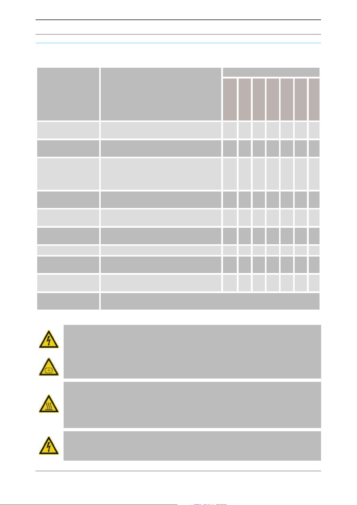
The table below shows an overview of the regular maintenance tasks. The individual tasks
are described in detail on the following pages.
Component Maintenance task Maintenance interval
daily
monthly
Six-monthly
annually
every 2 years
every 4 years
see page
Entire dryer Complete visual inspection and function
test.
Heater Inspect intake opening for regeneration
gas.
Switch cabinet Check that the screw connections and
clamps are secured; tighten if necessary.
(Reduce maintenance intervals in the event
of heavy vibrations.)
Silencer Renew silencer every year and after desic-
cant renewal.
Control air lter Inspect control air lter and clean or
replace, if necessary.
Dewpoint transmitter
Vacuum pump Inspect bearing and replace, if necessary
Dust lter Check dust lter for contamination and
Desiccant Check desiccant for contamination and
Preliminary and
after lter (optional)
Renew
clean, if necessary.
replace, if necessary.
Please refer to the manuals of the installed lters for details on the maintenance
tasks to perform.
•
•
•
••
•
•
•
41
41
41
42
42
42
44
44
•
44
•
When carrying out any maintenance work, please observe the following safety instructions:
Danger!
Working on the dryer when it is switched on and under pressure entails a substantial risk of injury.
Before starting maintenance work, always shut down the dryer as described on
page „Depressurising and shutting down the dryer“ 37 !
Risk of injury posed by hot surfaces!
The dryer’s surfaces may remain very hot even after it is switched off. Do not
touch hot surfaces!
Wait until the surfaces have cooled down suffi ciently before starting work on
the dryer.
Electric current warning!
Work on the electric system must only be carried out by qualifi ed technical
personnel!
40 WVM 40 -1450
Page 41

EN | Operating manual Maintenance and repair of the dryer
Cleaning
Remove dust with dry cloth; use moist cloth, if necessary.
Clean all surfaces, e.g. at the operating panel, with a moist cloth.
Daily maintenance tasks
Complete visual inspection and function test of the entire dryer
Inspect dryer for visual damage and unusual noises.
If your dryer is not connected to a fault signalling system (see page 28), check whether
there is an error message on the display at the switch cabinet. Assess any existing fault messages (heed the malfunction table in the controller manual!).
Check whether compressed air has reached the set pressure dewpoint. In units equipped
with dewpoint-dependent control (optional), the dewpoint is shown at the display.
Check dam pressure
If, following depressurisation of a vessel, e.g. after the expansion phase, the overpressure
has not decreased to < 0,5 bar, then there is a residual pressure, designated as dam pressure, in the vessel.
Check for dam pressure: if the dryer functions correctly, the respective pressure gauge
indicates < 0,5 bar. Then there is no dam pressure.
If the dam pressure is greater than < 0,5 bar:
Depressurise the dryer and shut it down (see page „Depressurising and shutting down the
dryer“ 37).
Dam pressure can be caused by:
◊ a blocked muf er,
◊ a malfunction of the expansion valve,
◊ a leaking pressure build-up valve.
The respective necessary maintenance measures are described in the following sections.
Monthly maintenance
Inspect intake opening for regeneration gas
The regeneration gas is fed to the system through an intake opening at the heater.
Wait until the dryer has reached the stand-by phase (see page „Stand-by-phase (for
dewpoint measurement option)“ 17).
Work with care and do not touch hot surfaces:
— ...After the vacuum pump has stopped, inspect screws at the intake opening and retighten, if necessary.
— ...Remove dirt from the screen covering the opening, using a suitable tool (e.g. soft wire
brush).
Note:
It is feasible to install an intake fi lter or to supply the regeneration air to the
dryer via an air duct if the ambient air is heavily soiled. Please note the respective hints in sections Options.
Six-monthly maintenance work
Check the screw and clamp connections
After six months at the latest, all the switch cabinet’s screw and clamp connections must be
checked to ensure that they are secure. The maintenance interval should be reduced in the
case of a vibrating substrate or a vibrating compressor feed line.
De-pressurize the dryer and shut it down (see page 37).
WVM 40 -1450 41
Page 42
EN | Operating manual Maintenance and repair of the dryer
Switch off the electric power feed, and take precautions to prevent it being switched back
on.
Check that all the screw connections and clamps in the switch cabinet are secure, and
tighten if necessary.
Replace any corroded components immediately.
Switch the electric power supply back on and close the switch cabinet.
Restart the dryer.
Maintenance work to be completed every 12 months
Replacing the silencer
The dryer is equipped with silencers. A ram pressure builds up when a silencer is blocked,
which could even cause the silencer to burst.
Risk posed by a blocked silencer!
Dangerous excess pressure may develop at blocked silencers, causing the
silencers to burst. Flying debris could injure persons and damage property.
Silencer elements should therefore be checked annually and replaced if soiled.
Beware of sudden air blast!
Pressure suddenly escapes via the silencer during expansion:
- A loud expansion noise occurs which may damage your hearing.
- Particles carried along with the air fl ow can damage your eyes or skin.
For this reason you must always wear eye and hearing protection when you are
near the dryer!
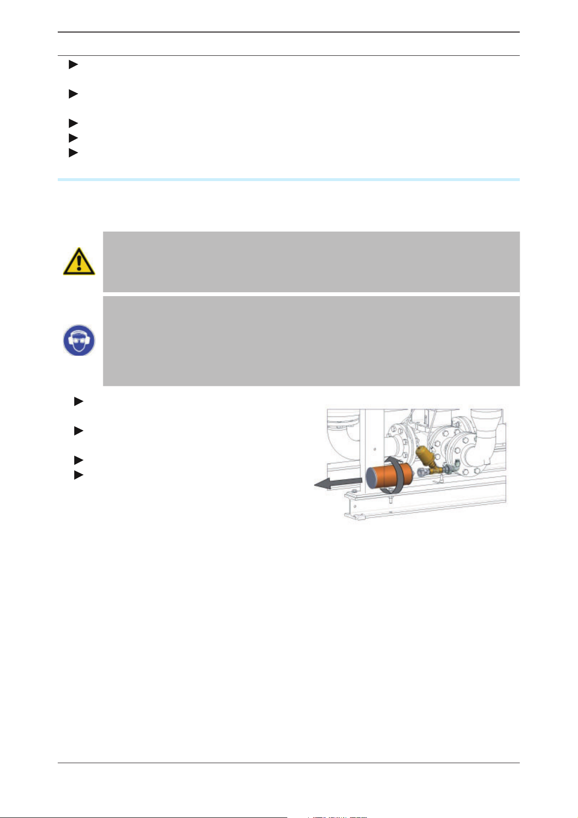
De-pressurize the dryer and shut it down
(see page 37)
Unscrew the silencer as shown in the illust-
ration to the right.
Fit new silencer in place and screw tight.
Restart the dryer (see page 38).
Unscrewing the silencer
Renew fi lter element of the control air fi lter
The control air lter is used to clean the control air and thus ensures that the valve actuators
are working properly. Contaminated or damaged control air lters might lead to malfunctions
in the valve actuators. The lter must therefore be inspected at least once every year.
42 WVM 40 -1450
Page 43
EN | Operating manual Maintenance and repair of the dryer
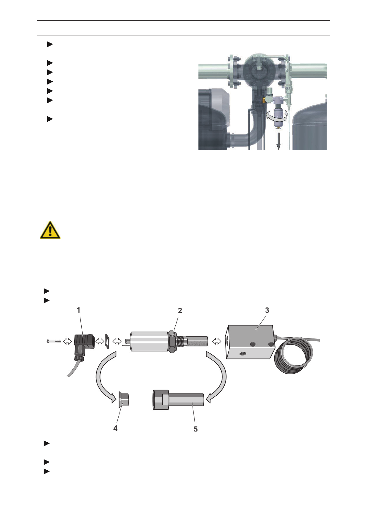
Depressurise dryer and take out of service
(see page 37).
Remove the base of the lter housing.
Remove lter element by turning it.
Renew lter element.
Mount the base of the lter housing.
Dispose of spent lter element according to
the statutory regulations.
If no other maintenance work is required:
Restart dryer (see page 38). Check lter for
leaks.
Open control air fi lter
Renew dewpoint sensor
In order to ensure accurate dew¬point measuring, we recommend annually renew the dewpoint sensor at least every 12 months. The recalibration must be carried out by the manufacturer. This period depends however on the actual application and might thus be extended
accordingly.
Warning!
The dew point sensor is a sensitive measuring device. It can be damaged if
subjected to forceful vibrations or shocks. Therefore, please handle the dew
point sensor with great care at all times.
In order to limit the impact on the dryer operation to a minimum, we recommend that you
contact the manufacturer well in advance (for contact details, see page 6) and order a new
dewpoint sensor.
After receipt of the new pressure dewpoint sensor, replace the sensor as follows:
Hold the box of the dewpoint sensor ready.
Release pressure from dryer and shut down the unit (see page 36).
Loosen the screw at the adapter (1) and disconnect signal cable with the adapter and
seal.
Remove dewpoint sensor from the sensor cell (3) by turning the nut (2).
Take the new dewpoint sensor (2) from the box, remove the protective caps (4, 5) and
WVM 40 -1450 43
Page 44

EN | Operating manual Maintenance and repair of the dryer
screw it into the sensor chamber (3).
Place seal onto sealing face; connect adapter (1) and secure it by tightening the screw.
If no other maintenance work is to be carried out: Restart the dryer (see page 38).
Place the protective caps (4, 5) onto the old dewpoint sensor and dispose of it in a proper
manner.
Maintenance work to be completed every 24 months
Inspect vacuum pump bearing and replace, if necessary
Caution!
Maintenance work at the vacuum pump may only be carried out by authorised
and suitably qualifi ed technical personnel who have already successfully completed similar tasks.
Please contact us to arrange a visit by one of our service technicians. Alternatively, ask us for a training session for the servicing of the vacuum pump. You
will fi nd the telephone number of our customer services department on page 6.
Maintenance work to be completed every 48 months
To complete the following maintenance tasks, you must dismantle the pipe bridges and the
vessels. We therefore recommend that you carry out these tasks together.
Note:
In accordance with national regulations, a pressure vessel inspection may be
prescribed to be carried out at regular intervals by an independent supervisory
offi ce.
For an inspection of the pressure vessels, the drying agent must be removed as
described as follows.
When inspecting the pressure vessels, it is recommended to check the condition of all fi ttings such as e.g. sieve bottoms and dust sieves, including gaskets.
If necessary, these fi ttings must be cleaned or renewed.
In the event of comprehensive maintenance or repair tasks, contact the manufacturer (see page 8).
Replace desiccant sieve
Between vessel and upper arch pipe, desiccant sieves are tted which retain the drying agent
dust. If these desiccant sieves become blocked, a dam pressure is generated which can
cause compressed air uctuations in the compressed air system.
For disassembling the desiccant sieves, the entire arch pipe must be removed rst.
Risk of falls!
The dryer must not be misused as a climbing aid! The components have not
been designed for such loads and could fracture.
Only use approved climbing aids when disassembling the upper arch pipe.
44 WVM 40 -1450
Page 45
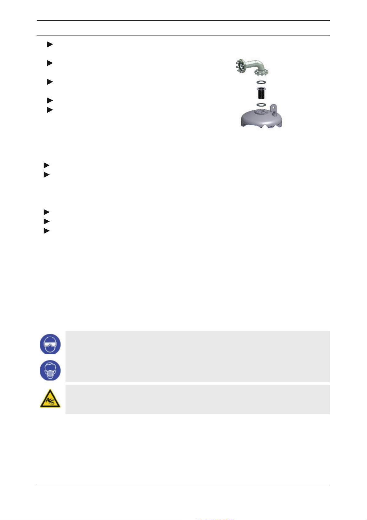
EN | Operating manual Maintenance and repair of the dryer
Depressurise dryer and take out of service
(see page 37).
Unscrew ange and screw connections
from the upper arch pipe system (see gure).
Withdraw upper arch pipe complete with all
mountings.
Remove desiccant sieves and gaskets.
Clean desiccant sieves with compressed
air or a suitable tool (e.g. soft wire brush).
Disassembling of desiccant sieve
Renew gaskets.
Mount cleaned desiccant sieves:
— mount base gasket;
— insert desiccant sieve;
— mount top gasket.
Repeat the process on the second vessel.
Re-mount and secure the upper arch pipe system.
If no other maintenance work is required: Restart dryer (see page 38). Check that the
connection is leak tight.
Renew desiccant
Generally desiccant has a service life up 3 to 5 years. Under favourable conditions, the
desiccant might not have to be replaced at that stage and can be used for longer period
(see also page 21). However, the service life depends greatly on the contamination of the
compressed air (or the effectiveness of the preliminary compressed air lter respectively) and
the contamination of the ambient air at the site. Oil, dust and dirt particles tend to deposit on
the desiccant and thus reduce the effective adsorption surface. This damage is not always
reversible. If in doubt, have your desiccant assessed by our specialists.
Please observe the following safety instructions when replacing the desiccant:
Wear eye protection and a dust mask because of increased dust formation!
Emptying the desiccant may lead to increased dust formation.
Wear goggles to avoid eye irritations!
Wear a dust mask to avoid inhaling the dust!
Risk of slipping!
Spilt desiccant beads lead to a risk of injury from slipping! Immediately remove
any spilt desiccant.
WVM 40 -1450 45
Page 46
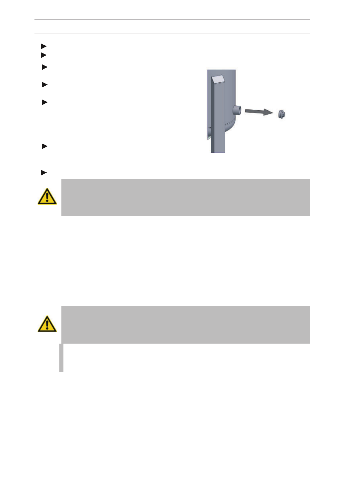
EN | Operating manual Maintenance and repair of the dryer
Remove spent desiccant
Release pressure from dryer and shut down the unit (see page 37).
Place suitable container below the discharge sleeve.
Remove the plug at the sleeve, using a
suitable tool.
Collect desiccant in the container positioned
below the sleeve.
Remove any desiccant left in the vessel
by using an industrial vacuum cleaner at the
sleeve. This procedure also cleans the screen
base and removes any residual material and
deposits.
Equip the sleeve plug with a non-locking
thread seal and screw in. Check thread seal and
replace, if necessary.
Removing plug from fi ller sleeve
Repeat the procedure for the second vessel.
Caution!
If the dryer has been improperly operated, the desiccant might be contaminated with pollutants. Please take this into account when disposing of the
desiccant.
Notes on the disposal of used desiccant
As the used desiccant is contaminated with various substances, its properties differ from
those of new desiccant. For this reason, the manufacturer or supplier of desiccant cannot
give any information on the used product.
Deliver used desiccant to a controlled dumping while heeding local of cial regulations.
Waste codes
◊ Unused product: 060899 (European waste code).
◊ Used product: These codes are governed by the industrial use and must therefore be deter-
mined by the waste originator.
Filling vessel with new desiccant
Risk of falling!
Do not use the dryer as a climbing aid. The components are not designed to
bear such a load and may break.
Only use approved climbing aids when fi lling the vessel.
Note:
Filling can also occur via the main line socket. This is feasible if the desiccant
sieve is also cleaned or replaced (see page 44).
46 WVM 40 -1450
Page 47
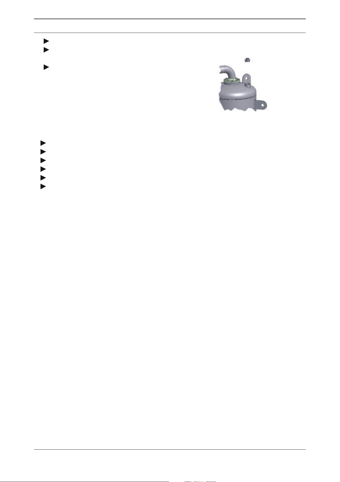
EN | Operating manual Maintenance and repair of the dryer
Ensure that discharge sleeve is closed.
Unscrew the plug of the lling hole with a
suitable tool (see illustration).
Slowly ll in new desiccant and make sure
to heed the next step. Use a funnel if necessary.
Unscrew the sleeve plug
Make sure to compact the lling in the vessel.
Equip the sleeve plug with a non-locking thread seal and screw in.
Repeat the procedure for the second vessel.
Restart the dryer if no other maintenance work is required.
Operate the dryer for two cycles, then shut it down again.
Replace silencer as described on page 42 and restart the dryer.
WVM 40 -1450 47
Page 48
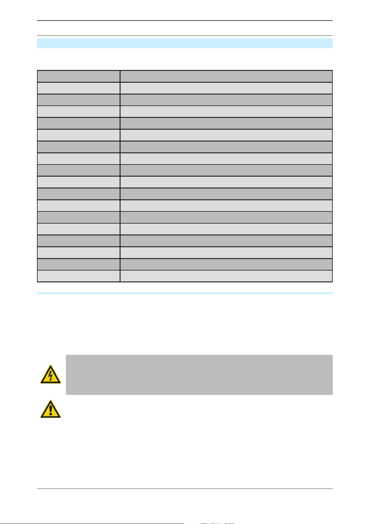
EN | Operating manual Identify and eliminate faults
Identify and eliminate faults
The following table provides information on what designatory abbreviations are to be used for
the various components. These designations are also found in the technical documentation.
Abbreviation Component
AA Fittings, general
AK Butter y valve
AR Check valve
AU Cardan shaft
AV 4/2-way tap cock
BB Dummy plug/ ange
BF Sieve bottom/desiccant sieve/ ow distributor
BS Silencer
BT Dessicant
GS Limit position monitor
H Air heater
MT Moisture measurement/pressure dewpoint
PT Pressure measurement
PI Pressure gauge
TT Temperature measurement
TSH Delimiter thermostat
V Vacuum pump
Notes on error messages and errors
The error message from the dryer are displayed on the operating panel. The controller manual
provides appropriate information. You are given information on the possible causes for the
error and tips how to eliminate the error.
If the dryer is connected to a fault signalling system, all error messages are transmitted
through the potential-free busbar connection to the operator’s control room.
Also heed the following notes when working at the electric system:
Electric current warning!
Work on the electrical system must only be carried out by qualifi ed technical
personnel! The electropneumatic switch cabinet in particular must be opened
and serviced by an instructed trained electrician only.
Caution!
Arbitrary changes to the factory settings of the control programme may result
in damage to the dryer.
48 WVM 40 -1450
Page 49

EN | Operating manual Appendix: Technical Documents
Appendix: Technical Documents
The appendix of this operating manual contains the following technical documents and data:
◊ Technical data
◊ List of service and desiccant kits
◊ Process diagram
◊ Pneumatic diagram of the control air unit
◊ Dimension drawing
◊ Electrical diagrams
◊ Declaration of Conformity
WVM 40 -1450 49
Page 50
EN | Operating manual Appendix: Technical Documents
Technical data – overview of standard dryers
Note:
For dimensions and weight of the dryer refer to the enclosed dimensional
drawing!
Nominal capacity*
DTP -25°C
TIPO m³/h m³/h kW Kg Kg m³/h mbar
WVM 40 420 378 5,55 770 ~136 125 25
WVM 50 510 459 5,55 770 ~171 125 25
WVM 65 640 576 9,70 800 ~207 210 25
WVM 85 850 765 9,70 800 ~260 210 25
WVM 120 1180 1062 13,40 1150 ~400 300 25
WVM 150 1500 1350 18,20 1300 ~470 375 25
WVM 200 1980 1782 23,70 1650 ~656 550 25
WVM 235 2350 2115 36,70 2000 ~827 750 25
WVM 300 2930 2637 36,70 2250 ~910 750 25
WVM 355 3550 3195 43,70 2650 ~1178 900 25
WVM 410 4100 3690 43,70 3250 ~1348 900 25
WVM 475 4740 4266 48,70 3650 ~1652 1150 25
DTP -40°C
Total connected load
Weight
Desiccant per dryer
Flow rate of vacuum
pump**
permissible pressure
difference when one
outgoing line
WVM 525 5250 4725 63,20 4050 ~1718 1460 25
WVM 620 6210 5589 73,20 4700 ~2153 1460 25
WVM 710 7100 6390 84,20 5050 ~2425 1800 25
WVM 800 8000 7200 89,20 6450 ~2967 1800 25
WVM 920 9200 8280
WVM 1080 10800 9720 8700 ~
WVM 1230 12300 11070 11900 ~
WVM 1450 14500 13050 15870 ~
* relative to 1 bar (abs.) and 20 °C at 7 bar operating pressure and a feed temperature of 35
°C and a pressure dewpoint of -25 °C.
** related to a differential pressure of 100 mbar.
On
request
7500 ~
On request
50 WVM 40 -1450
Page 51
EN | Operating manual Appendix: Technical Documents
Fill quantities Dessicant
B1 B2
Top Silica gel Silica gel
Bottom waterproof Silica gel waterproof Silica gel
Note on load cycle calculation:
According to the EC pressure equipment directive the dryers are rated for
14,000 load cycles. This corresponds to a service life of approx. 20 years when
operated in the fi xed cycle of 6 hours (12 h total cycle time). 1 load cycle corresponds to the change from the unpressurised state to operating pressure.
When the pressure vessels are approved according to other
Typ WVM 40 – WVM 1450
Fluid class (according to PED) 2
Supply voltage see type plate
Protection class IP54
min max
Operating overpressure (bar) see type plate
Ambient temperature (°C) 1 50
Max. intake temperature for regeneration air (°C)
(please heed the table below that relates the moisture of the intake
air to the temperature)
Max. dust contents of the regeneration air (mg/m)* - 50
Noise level : +3 dB (A) related to free- eld measurement, 1 m
surrounding eld db(A)
* Note: Provide for an appropriate dust lter when the regeneration air taken in
has a higher dust load. Contact the manufacturer in this case!
Regeneration air – maximum relative humidity at defi ned intake temperature
max. rel. humidity (%) at intake temperature (°C)
90 20
70 25
50 30
37 35
140
75 90
25 40
WVM 40 -1450 51
Page 52

EN | Operating manual Appendix: Technical Documents
Spare parts list
Note:
When exchange or replacement parts are ordered, always state the dryer type
and the build no. of the dryer. These data are found on the type plate.
Service kits (wear parts kits, valid for 10 bar variants)
Order no. For model Maintenance
interval
SKW40-W1450/VM4/12 WVM 40 - 1450 12/36 month
SKW40-W355/VM4/24 WVM 40 - 355 24 month
SKW410-W710/VM4/24 WVM 410 - 710 24 month
SKW800-W1080/VM4/24 WVM 800 - 1080 24 month
SKW1230-W1450/VM4/24 WVM 1230 - 1450 24 month
SKW40-W50/VM4-E/48 WVM 40 - 50 48 month
SKW65-W85/VM4-E/48 WVM 65 - 85 48 month
SKW120-W200/VM4-E/48 WVM 120 - 200 48 month
SKW235-W355/VM4-E/48 WVM 235 - 355 48 month
Volume di fornitura
Control air lter element,
pilot valves
Control air lter element,
pilot valves, wear parts kit
for the expansion valve
(V5), wear parts kit for the
pressure build-up valve (V4)
Control air lter element,
magnet valve, wear parts
kit for the expansion valve
(V5), wear parts kit for the
pressure build-up valve
(V4), wear parts kit for the
regeneration gas ap (V3),
check valve (RV)
SKW410-W710/VM4-E/48 WVM 410 - 710 48 month
SKW800-W1080/VM4/48 WVM 800 - 1080 48 month
SKW1230-W1450/VM4/48 WVM 1230 - 1450 48 month
52 WVM 40 -1450
Page 53

EN | Operating manual Appendix: Technical Documents
Desiccant packs*
For model Order no. For model Order no.
WVM 40 WVM40DESMIX WVM 410 WVM410DESMIX
WVM 50 WVM50DESMIX WVM 475 WVM475DESMIX
WVM 65 WVM65DESMIX WVM 525 WVM525DESMIX
WVM 85 WVM85DESMIX WVM 620 WVM620DESMIX
WVM 120 WVM120DESMIX WVM 710 WVM710DESMIX
WVM 150 WVM150DESMIX WVM 800 WVM800DESMIX
WVM 200 WVM200DESMIX WVM 920 WVM920DESMIX
WVM 235 WVM235DESMIX WVM 1080 WVM1080DESMIX
WVM 300 WVM300DESMIX WVM 1230 WVM1230DESMIX
WVM 355 WVM355DESMIX WVM 1450 WVM1450DESMIX
WVM 40 -1450 53
Page 54

EN | Operating manual Appendix: Technical Documents
Spare parts
For model Order no. Quantity Purchased parts package
WVM 40-50 GASKIT40W 1 Flat gasketsDN40
WVM 65-85 GASKIT50W 1 Flat gasketsDN50
WVM 120-200 GASKIT80W 1 Flat gasketsDN80
WVM 235-355 GASKIT100W 1 Flat gasketsDN100
WVM 410-710 GASKIT150W 1 Flat gasketsDN150
WVM 800-1080 GASKIT200W 1 Flat gasketsDN200
WVM 1230-1450 GASKIT250W 1 Flat gasketsDN250
WVM 40-355 SDD-25/AL 1 Silencers
WVM 410-1080 SDD-25/AL 2 Silencers
WVM 1230-1450 SDD-40/AL 6 Silencers
WVM 40-1450 ZHM100/450 1 dewpoint sensor
WVM 40-50 RKSCD-F40/16/VA 1 ow distributors
WVM 65-80 RKSCD-F50/16/VA 1 ow distributors
WVM 120-200 RKSCD-F80/16/VA 1 ow distributors
WVM 235-355 RKSCD-F100/16/VA 1 ow distributors
WVM 410-710 RKSCD-F150/16/VA 1 ow distributors
WVM 800-1080 RKSCD-F200/16/VA 1 ow distributors
WVM 1230-1450 RKSCD-F250/16/VA 1 ow distributors
54 WVM 40 -1450
Page 55

Page 56
A division of Parker Hannifin Corporation
Parker Hannifin Manufacturing S.r.l.
Sede Legale: Via Privata Archimede, 1- 2009 Corsico (MI) Italy
Sede Operativa: Gas Separation and Filtration Division EMEA - Strada Zona
Industriale, 4
35020 S.Angelo di Piove (PD) Italy
tel +39 049 971 2111- fax +39 049 9701911
Web-site: www. parker.com/hzd
e-mail: [email protected]
 Loading...