

Page 1

Vansco Multiplexing Module
VMM2404
U s er G u i d e
HY33-5011-IB/US
UG-VMM2404-0837001-201705-002
Page 2

Parker Hannifin Canada
Electronic Controls Division
1305 Clarence Avenue
Winnipeg, MB R3T 1T4 Canada
office +1 204 452 6776
Fax +1 204 478 1749
http://www.parker.com/ecd
Copyright 2017 © Parker Hannifin Corporation. All rights reserved. No part of this work may be
reproduced, published, or distributed in any form or by any means (electronically, mechanically,
photocopying, recording, or otherwise), or stored in a database retrieval system, without the prior
written permission of Parker Hannifin Corporation in each instance.
Warning!
FAILURE OR IMPROPER SELECTION OR IMPROPER USE OF THE PRODUCTS AND/OR SYSTEMS
DESCRIBED HEREIN OR RELATED ITEMS CAN CAUSE DEATH, PERSONAL INJURY AND PROPERTY
DAMAGE.
This document and other information from Parker Hannifin Corporation, its subsidiaries and authorized
distributors provide product and/or system options for further investigation by users having technical expertise.
The user, through its own analysis and testing, is solely responsible for making the final selection of the
system and components and assuring that all performance, endurance, maintenance, safety and warning
requirements of the application are met. The user must analyze all aspects of the application, follow applicable
industry standards, and follow the information concerning the product in the current product catalog and in any
other materials provided from Parker or its subsidiaries or authorized distributors.
To the extent that Parker or its subsidiaries or authorized distributors provide component or system options
based upon data or specifications provided by the user, the user is responsible for determining that such data
and specifications are suitable and sufficient for all applications and reasonably foreseeable uses of the
components or systems.
Offer of Sale
The items described in this document are hereby offered for sale by Parker Hannifin Corporation, its subsidiaries
or its authorized distributors. This offer and its acceptance are governed by the provisions stated in the "Offer of
Sale" elsewhere in this document, or available at www.parker.com.
Page 3

User Guide iii
Publication History .............................................................................................................. vi
Safety ................................................................................................................................... vii
Safety symbols ................................................................................................................................ vii
General safety regulations .............................................................................................................. vii
Welding after installation ................................................................................................................ viii
Construction regulations ................................................................................................................ viii
Safety during installation ................................................................................................................ viii
Safety during start-up ....................................................................................................................... ix
Safety during maintenance and fault diagnosis ............................................................................... ix
1. About the VMM2404 .......................................................................................................... 1
1.1. Diagram conventions ................................................................................................................ 2
2. Quick Start ......................................................................................................................... 5
2.1. Overview ................................................................................................................................... 5
2.2. Gather Required Materials ........................................................................................................ 5
2.3. Install the Required Software Tools .......................................................................................... 6
2.3.1. Install the Data Link Adapter Driver Software ............................................................. 6
2.4. Connect the VMM2404 multiplexing module to a Development System .................................. 7
2.4.1. Power Up the Development System ........................................................................... 8
2.5. Create and Download Ladder Logic Applications ..................................................................... 9
3. Inputs ............................................................................................................................... 10
3.1. Programmable Multi-Purpose Inputs ...................................................................................... 10
3.1.1. Multi-Purpose Used as Programmable Digital Input ................................................. 10
3.1.2. Multi-Purpose Used as Analog Input ......................................................................... 12
3.1.3. Multi-Purpose Used as AC-Coupled Frequency Input .............................................. 16
3.1.4. Multi-Purpose Used as DC-Coupled Frequency Input .............................................. 18
3.2. Digital Inputs ........................................................................................................................... 21
3.2.1. Programmable Digital Inputs ..................................................................................... 21
3.2.2. Power Control Digital Inputs ...................................................................................... 23
3.2.3. Addressing Digital Inputs ........................................................................................... 25
4. Outputs ............................................................................................................................ 28
4.1. High-side outputs .................................................................................................................... 28
4.1.1. High-Side Output Capabilities ................................................................................... 28
4.1.2. High-Side Output Installation Connections ................................................................ 29
4.1.3. High-Side Output Diagnostics and Fault Protection .................................................. 30
Contents
Page 4

iv VMM2404
Contents
4.2. Low-Side Outputs with Current Sense .................................................................................... 31
4.2.1. Low-Side Outputs with Current Sense Capabilities ................................................... 31
4.2.2. Low-Side Outputs with Current Sense Configuration Options ................................... 33
4.2.3. Low-Side Outputs with Current Sense Installation Connections ............................... 33
4.2.4. Low-Side Outputs with Diagnostics and Fault Protection .......................................... 34
5. Power ............................................................................................................................... 35
5.1. Logic and output power ........................................................................................................... 35
5.1.1. Logic and Output Power Capabilities ......................................................................... 35
5.1.2. Logic and output power connections ......................................................................... 36
5.2. Sensor supply .......................................................................................................................... 37
5.2.1. Sensor Power Capabilities ......................................................................................... 37
5.2.2. Sensor Power Connections........................................................................................ 38
6. Communication ............................................................................................................... 39
6.1. Controller area network ........................................................................................................... 39
6.1.1. J1939 CAN Capabilities ............................................................................................. 39
6.1.2. J1939 CAN Installation Connections ......................................................................... 39
7. Diagnostic LEDs ............................................................................................................. 42
7.1. Input LEDs ............................................................................................................................... 42
7.2. Output LEDs ............................................................................................................................ 42
7.3. Power LED............................................................................................................................... 42
7.4. Network LED............................................................................................................................ 43
8. Connectors ...................................................................................................................... 44
8.1. Mating Connector Part Numbers ............................................................................................. 45
8.2. Pinouts ..................................................................................................................................... 45
9. Installation ....................................................................................................................... 48
9.1. Mechanical Installation Guidelines .......................................................................................... 48
9.1.1. Dimensions ................................................................................................................ 48
9.1.2. Selecting a Mounting Location ................................................................................... 48
9.1.3. Mounting the VMM2404 to a Vehicle ......................................................................... 50
9.2. Electrical Installation Guidelines .............................................................................................. 50
9.2.1. Designing and Connecting the Vehicle Harness ....................................................... 50
10. Application Examples ................................................................................................... 51
10.1. Implementing Safety Interlocks ............................................................................................. 51
10.2. Controlling Indicator Lights .................................................................................................... 52
10.3. Controlling a Proportional Valve ............................................................................................ 53
10.4. Controlling Motor Speed ........................................................................................................ 55
10.5. Using one Analog Input as Two Digital Inputs ....................................................................... 56
10.6. Controlling a Linear Actuator ................................................................................................. 57
10.7. Connecting Various Sensors ................................................................................................. 58
10.7.1. Open Collector ......................................................................................................... 58
10.7.2. Variable Resistance ................................................................................................. 60
10.7.3. Variable Reluctance ................................................................................................. 61
10.7.4. Switch ....................................................................................................................... 61
10.7.5. Voltage ..................................................................................................................... 62
Page 5

User Guide v
Contents
10.7.6. CMOS ...................................................................................................................... 63
10.7.7. Potentiometer (Ratiometric) ..................................................................................... 64
11. Tests ............................................................................................................................... 65
12. Frequently Asked Questions (FAQ) ............................................................................ 67
13. Troubleshooting ............................................................................................................ 71
14. Glossary ......................................................................................................................... 72
15. Index ............................................................................................................................... 79
Page 6
User Guide vi
The following table provides an overview of the changes made to this document
over the course of its publication history.
Revision
Description of Change
Rev. 001
First release of this document
Rev. 002
New template, minor edits 05/2017
Publication History
Page 7

User Guide vii
Do not perform the procedures in this manual unless you are experienced in the
handling of electronic equipment.
Contact the manufacturer if there is anything you are not sure about or if you have
any questions regarding the product and its handling or maintenance.
The term "manufacturer" refers to Parker Hannifin Corporation.
Safety symbols
The following symbols are used in this document to indicate potentially
hazardous situations:
Danger! Risk of death or injury.
Warning! Risk of damage to equipment or degradation of signal
When you see these symbols, follow the instructions carefully and proceed with
caution.
General safety regulations
Work on the hydraulics control electronics may only be carried out by trained
personnel who are well-acquainted with the control system, the machine, and its
safety regulations.
Follow the manufacturer's regulations when mounting, modifying,
repairing, and maintaining equipment. The manufacturer assumes no
responsibility for any accidents caused by incorrectly mounted or
incorrectly maintained equipment. The manufacturer assumes no
responsibility for the system being incorrectly applied, or the system
being programmed in a manner that jeopardizes safety.
Safety
Page 8

viii VMM2404
Safety
Do not use the product if electronic modules, cabling, or connectors are
damaged or if the control system shows error functions.
Electronic control systems in an inappropriate installation and in
combination with strong electromagnetic interference fields can, in
extreme cases, cause an unintentional change of speed of the output
function.
Welding after installation
Complete as much as possible of the welding work on the chassis before the
installation of the system. If welding has to be done afterwards, proceed as
follows:
Do not place the welding unit cables near the electrical wires of the
control system.
1. Disconnect the electrical connections between the system and external
equipment.
2. Disconnect the negative cable from the battery.
3. Disconnect the positive cable from the battery.
4. Connect the welder's ground wire as close as possible to the place of the
welding.
Construction regulations
The vehicle must be equipped with an emergency stop which disconnects the
supply voltage to the control system's electrical units. The emergency stop must
be easily accessible to the operator. If possible, the machine must be built so that
the supply voltage to the control system's electrical units is disconnected when the
operator leaves the operator’s station.
Safety during installation
Incorrectly positioned or mounted cabling can be influenced by radio
signals, which can interfere with the functions of the system.
Page 9

User Guide ix
Safety
Safety during start-up
Danger! Risk of death or injury. Do not start the machine's engine
before the control system is mounted and its electrical functions have
been verified.
Do not start the machine if anyone is near the machine.
Safety during maintenance and fault diagnosis
Before performing any work on the hydraulics control electronics, ensure that
The machine cannot start moving.
Functions are positioned safely.
The machine is turned off.
The hydraulic system is relieved from any pressure.
Supply voltage to the control electronics is disconnected.
Page 10

Page 11
User Guide 1
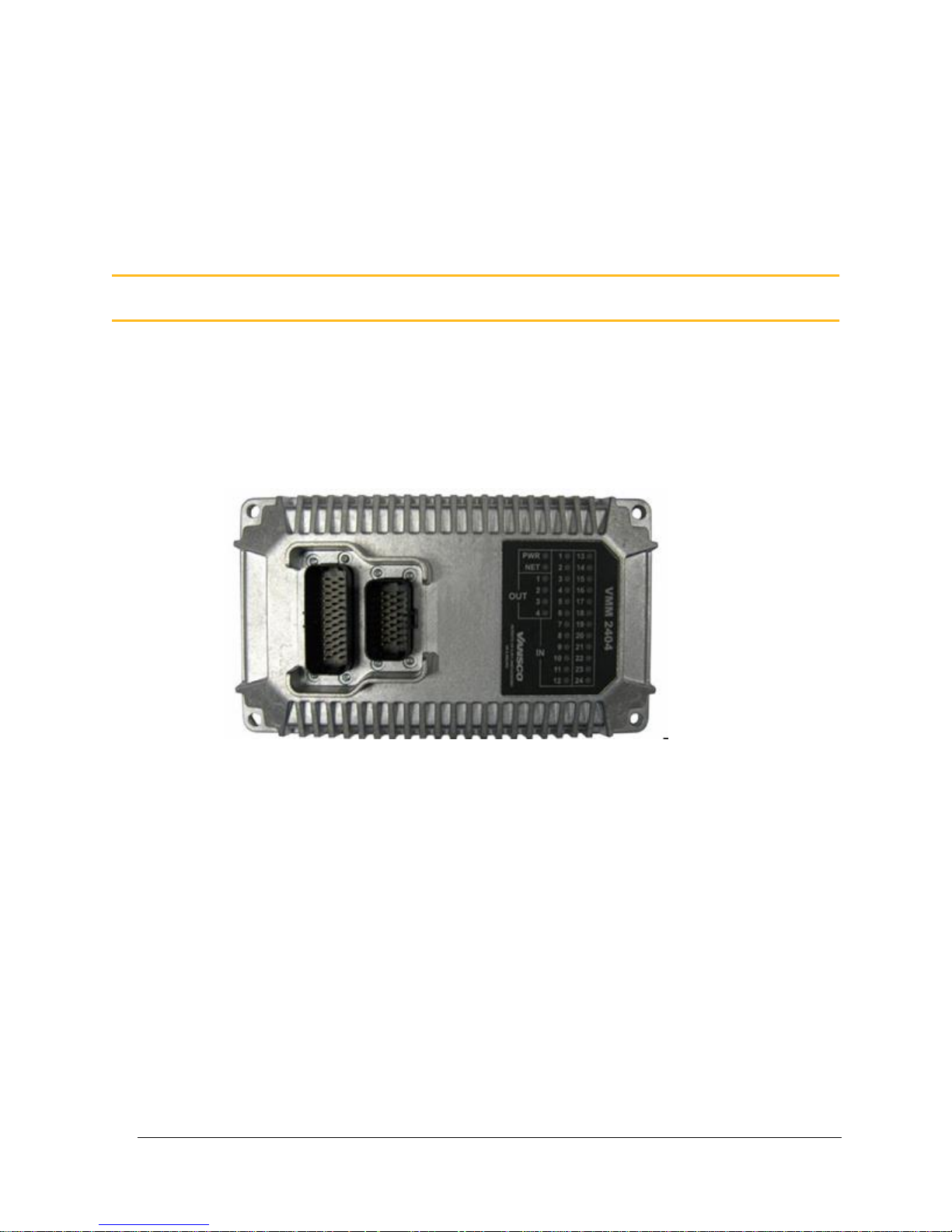
The Vansco Multiplex Module (VMM) 2404 is a software-programmable,
multiplexing, input/output controller that monitors dedicated and general-purpose
inputs, and controls solid-state-switch outputs.
The VMM modules can be configured to meet many system requirements through
I/O configuration options and ladder logic software.
Figure 1: VMM2404
The VMM2404 is designed to communicate through a J1939-based Controller
Area Network (CAN). Custom CAN messaging can be created in software, and
the VMM2404 can be used in any CAN 2.0B application.
The VMM2404 is controlled by ladder logic software.
You can write the software in ladder logic using the Vansco Multiplex
Module Software (VMMS) tool. Contact your Parker Vansco Account
Representative for more details about the VMMS.
The VMM2404 has many features, as follows
The VMM2404 can monitor up to 30 inputs:
15 general-purpose inputs (can be used as digital, analog, or frequency)
9 programmable digital inputs (can be active-high or active-low)
1. About the VMM2404
Page 12

2 VMM2404
About the VMM2404
5 digital inputs (active-low inputs used for harness addressing)
1 power control input
The VMM2404 has 8 outputs, rated at 3 A maximum current:
4 high-side outputs
4 low-side outputs with current sense (these outputs monitor current, and
can be used for current feedback if a high-side output is used for pulsewidth modulation)
The VMM2404 has two Ampseal connectors (23 pin and 35 pin) that are used
to interface with the inputs, outputs, and CAN
The VMM2404 has 30 LEDs that can be used to indicate the state and fault
status of inputs, outputs, power, and CAN
The VMM2404 can detect and log the following faults:
Short-circuit
Overcurrent
Open load
Short-to-battery
Short-to-ground
This manual describes the hardware components of the VMM2404, but does not
explain how to write or configure the software. For more information about
software, refer to the appropriate software manual or contact your Parker Vansco
Account Representative.
1.1. Diagram conventions
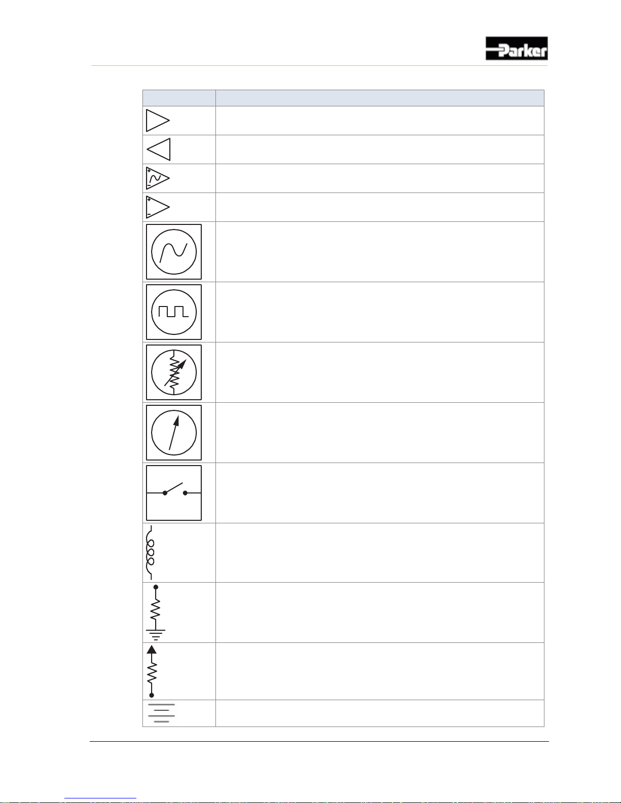
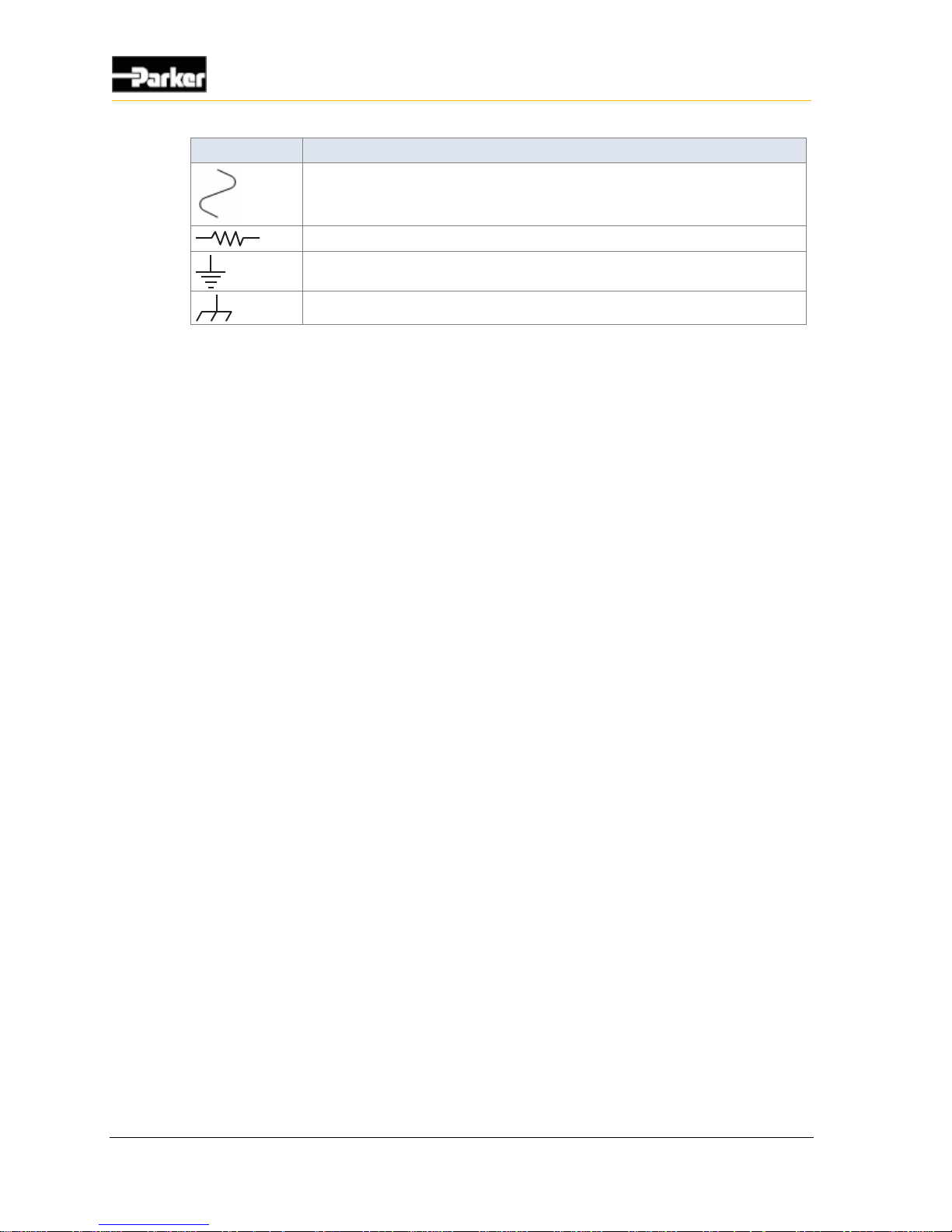
The following symbols are used in the schematic diagrams in this document:
Page 13
User Guide 3
About the VMM2404
Symbol
Meaning
General input
General output
Frequency input
Analog input
Frequency sensor
Pulse sensor
Resistive sensor
General sensor
Application switch
Load
Pull-down resistor
Pull-up resistor
Battery
Page 14
4 VMM2404
About the VMM2404
Symbol
Meaning
Fuse
Resistor
Ground
Chassis ground
Page 15

User Guide 5
Quick Start
This section provides step-by-step instructions on how to connect the VMM2404
multiplexing module to a development system, install the required software tools,
and download the application software.
2.1. Overview
The following is a high-level overview of the steps involved with this section:
1. Gather the required materials.
2. Install the required software tools provided by Parker Vansco.
3. Connect the VMM2404 to a development system (desktop) and power it up.
4. Download application software.
2.2. Gather Required Materials
The following materials are required for the procedures in this section:
VMM2404 multiplexing module
personal computer (PC)
controller I/O board
controller I/O harness (connects the VMM2404 to the controller I/O board)
evaluation kit power harness (connects the controller I/O board to the power
supply)
Data Link Adapter (DLA) kit (comes with cables needed for connecting the
DLA to your PC and to the rest of the system)
desktop power supply compatible with the VMM2404 and controller I/O
board loads (a 12 V DC, 3 A fixed voltage supply is generally suitable, unless
driving more significant loads)
procurement drawing for the version of VMM2404 you are using, indicating
the configuration options for your variant of the product.
2. Quick Start
Page 16

6 VMM2404
Quick Start
software tools and files required for programming and downloading software
for the VMM2404.
Note: With the exception of the PC and desktop power supply, all materials
and software are available from Parker Vansco. Please consult your Parker
Vansco Account Representative for specific details and pricing information.
2.3. Install the Required Software Tools
Before using the VMM2404 multiplexing module, install the following software
tools onto your PC:
Data Link Adapter (DLA) drivers
The DLA acts as the interface between the PC and the VMM2404. Before
using the DLA, you must install the DLA drivers.
Parker Vansco Software Tools
Parker Vansco provides the VMMS software tool to create and download
software for the VMM2404 multiplexing module. Contact your Parker
Vansco Account Representative, or visit the Parker website to get further
information on how obtain a product key.
2.3.1. Install the Data Link Adapter Driver Software
A Data Link Adapter (DLA) is needed when connecting the VMM2404
multiplexing module in a development system.
Note: Parker Vansco provides the latest DLA software releases through its
web site. Please contact your Parker Vansco Account Representative for
details on how to download the latest DLA driver software.
The Parker Vansco DLA requires the installation of drivers on your PC. To install
the Parker Vansco DLA drivers:
1. Download the driver, run the extracted file, and follow the Install Wizard. Do
not connect the USB-DLA until the driver installation is completed.
2. Connect the USB-DLA to a USB port on your PC. The Found New Hardware
screen opens.
3. Select Install the software automatically (Recommended), and then click
Next. If the driver is not detected automatically, you can browse to the folder
containing the driver.
4. After installation is finished, click Finish. The USB-DLA is now recognized
and ready to be used.
See the Parker Vansco USB-DLA kit user manual for more detailed instructions.
Page 17
User Guide 7
Quick Start
2.4. Connect the VMM2404 multiplexing module to a
Development System
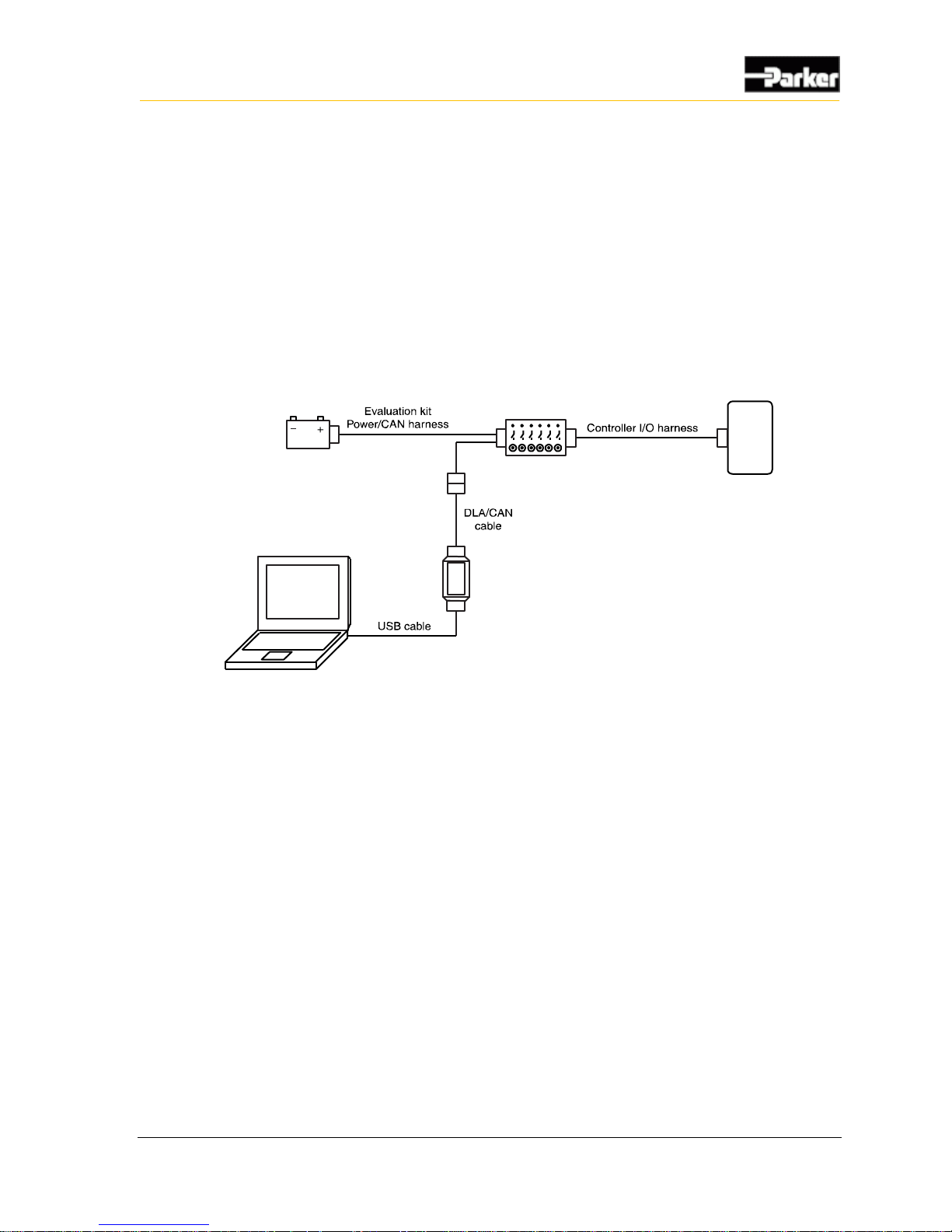
It is a good idea to connect the VMM2404 multiplexing module to a development
system (PC, Controller I/O Board, power source, and DLA) to verify your
application. The development system is an ideal environment for creating and
downloading software applications.
The following shows how to connect the VMM2404 multiplexing module in a
development system:
Controller
DLA
I/O Board
Power
PC
Figure 2: Development system connection
To connect the VMM2404 multiplexing module in a development system, do the
following:
Note: Before connecting anything in the development system, ensure that the
power supply is set to a voltage that is less than 32 V DC.
Page 18

8 VMM2404
Quick Start
1. Connect the Controller I/O harness to the VMM2404 multiplexing module.
2. Connect the Controller I/O harness to the controller I/O board connectors.
3. Connect the evaluation kit power/CAN harness to the controller I/O board’s
JP3 connector.
4. Do not connect the power wire (RED) from the evaluation kit power/CAN
harness to the power supply (+) terminal at this time.
5. Connect the ground wire (BLACK) from the evaluation kit power/CAN
harness to the power supply (-) terminal.
6. Connect the CAN connector from the evaluation kit power/CAN harness to
the corresponding mating connector and harness on the DLA.
Note: Do not proceed to the next step before the DLA drivers have been
installed. See Install the Data Link Adapter Driver Software on page 6.
7. Connect the DLA to a personal computer via the USB port.
2.4.1. Power Up the Development System
Once the VMM2404 is connected in a development system, you need to power it
up.
To power up the VMM2404 multiplexing module, do the following:
1. Ensure all controller I/O board digital inputs, jumpers, and dip switches are
properly configured for the VMM2404. Refer to the Controller I/O Board
Reference Manual for further details.
2. Connect the power wire (red) from the evaluation kit power/CAN harness to
the power supply (+), and turn the power supply on.
3. Turn on the controller I/O board switch that corresponds with the power
control input on the VMM2404 (refer to the Controller I/O Board Reference
Manual for details). The VMM2404 will power up.
Note: If the module does not power up and you are unsure if a power control
input is set on the VMM2404, try switching all the inputs on the controller I/O
board to high, and then to low. If you continue to have problems, consult the
Troubleshooting/FAQ section in the Controller I/O Board Reference Manual
for help.
Page 19

User Guide 9
Quick Start
2.5. Create and Download Ladder Logic
Applications
Software applications can be created and downloaded to the VMM2404
multiplexing module.
The software applications for the VMM2404 can be created with the Vansco
Multiplexing Module Software (VMMS) tool, using ladder logic.
Consult your Parker Vansco Account Representative for information about your
software programming options.
Page 20

10 VMM2404
Inputs
The VMM2404 has 3 main types of inputs, as follows:
Programmable digital inputs (can be used as active high, active low, or power
control)
Dedicated addressing inputs
Programmable multi-purpose inputs (can be used as analog, digital, or
frequency)
Note: Do not connect inputs directly to unprotected inductive loads such as
solenoids or relay coils, because they can produce high voltage spikes that
may damage the VMM2404. If an inductive load must be connected to an
input, use a protective diode or transorb.
3.1. Programmable Multi-Purpose Inputs
The VMM2404 has programmable multi-purpose inputs that can be configured
either as analog, digital, or frequency (ADF) through software, as follows:
INPUT1_ADF through INPUT15_ADF
3.1.1. Multi-Purpose Used as Programmable Digital Input
Digital inputs are typically used for electrical signals that are either on or off.
The following multi-purpose inputs can be used as digital inputs:
INPUT1_ADF to INPUT15_ADF
Note: There are 15 other digital inputs in addition to these inputs (refer to
Digital Inputs on page 21 for more details).
3. Inputs
Page 21
User Guide 11
Inputs
3.1.1.1. Digital Input Capabilities
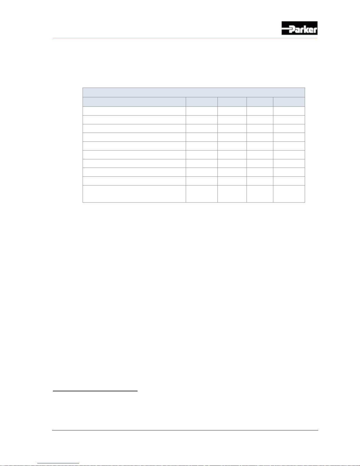
The following table provides specifications for the VMM2404’s standard digital
inputs:
Standard Digital Input Capabilities
Item
Min
Nom
Max
Unit
Input voltage range
0 - 32
V
Pull-up / pull-down resistance
3.1 k
-
3.5 k
Ω
Minimum negative going threshold
0.8 - -
V
Maximum positive going threshold
- - 1.19
V
Cutoff frequency (hardware)1
-
12
-
kHz
De-bounce time (software)2
25 - 50
ms
Overvoltage
- - 36
V
Wetting current @ 12 V
3.43
-
3.87
mA
Amplifier gain3
-
1.00
-
V/V
Leakage current sleep mode
- pin @ 12 V
- - 4.1
mA
3.1.1.2. Digital Input Configuration Options
Digital inputs can be programmed as either active high or active low, and they can
have a pull-up or pull-down resistance of 3.3 kΩ.
If the input is configured as active high, an internal pull-down resistor will be
used, and the input will be active when it is switched to battery voltage.
If the input is configured as active low, an internal pull-up resistor will be
used, and the input will be active when it is switched to ground.
3.1.1.3. Active-High Digital Input Connections
A digital input is typically connected to a switch that is either open or closed.
When an active-high switch is open, the pull-down resistor ensures that no
voltage exists on the input signal, which will be interpreted by the VMM2404
as inactive.
When the switch is closed, the input is connected to battery voltage, which
will be interpreted by the VMM2404 as active.
1
Assumes there is a zero ohm source impedance from driving source. The actual cutoff in the application will be partially
determined from the source impedance and VMM input capacitance.
2
De-bounce time is based on a sampling rate of 40 Hz.
3
Amplifier gain on digital inputs is only adjustable in "black box" software. It is only pre-set to the value in the table if using
ladder logic.
Page 22
12 VMM2404
Inputs
For an input that is active-high
It must be connected to battery power so that there is a battery connection
when the state of the input changes.
The power provided to the digital switch connected to the input must be
provided through a fuse in the wire harness.
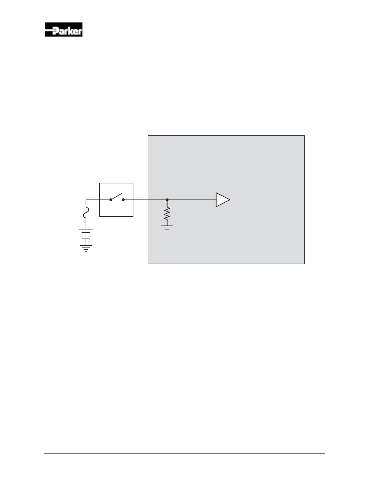
A typical active-high digital input connection is shown below:
Internal to product
Active High
Digital Input
Battery
Application Switch
Figure 3: Active high digital input
3.1.2. Multi-Purpose Used as Analog Input
Analog inputs are typically used to read electrical signals that span a voltage
range.
The following multi-purpose inputs can be used as analog inputs:
INPUT1_ADF to INPUT15_ADF
Page 23
User Guide 13
Inputs
3.1.2.1. Analog Input Capabilities
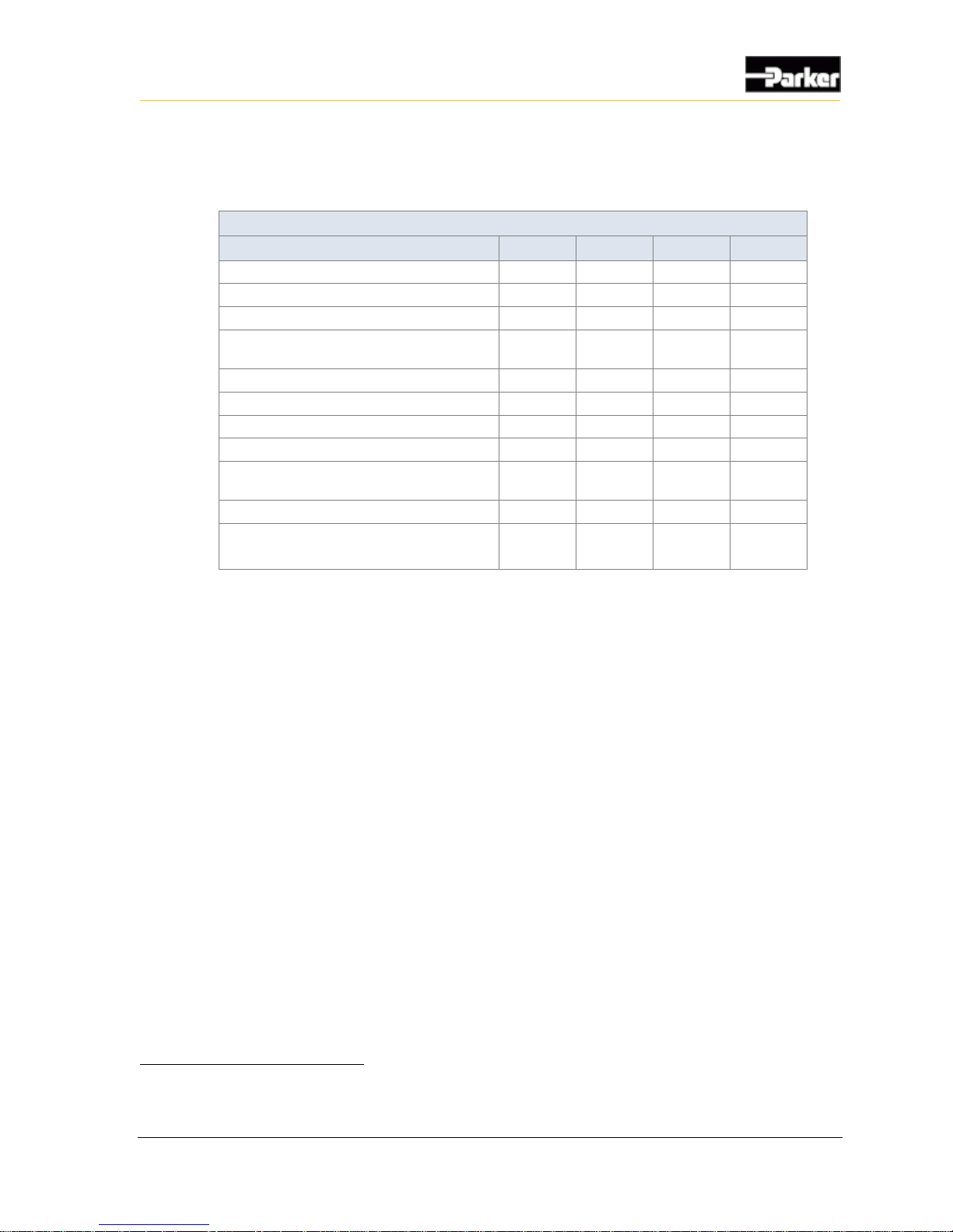
The following table provides specifications for the VMM2404 analog inputs:
Analog Input Specifications
Item
Min
Nom
Max
Unit
Input voltage range
0 - 32
V
Overvoltage
- - 36
V
Pull-up / down resistance
3.1 k
-
3.5 k
Ω
Input resistance – pull-up/pull-down
disabled
81 k - -
Ω
Input capacitance
9
10
11
nF
Cutoff frequency (hardware)4
-
12
-
kHz
Accuracy - -
3
%
Resolution5
4.375
-
4.422
mV
Analog gain
-
Program-
mable
-
V/V
Reference voltage
2.984
3.0
3.016
V
Leakage current sleep mode
- pin @ 12 V
- - 4.1
mA
3.1.2.2. Analog Input Configuration Options
If one of the VMM2404’s multi-purpose inputs is configured as an analog input,
the input will be converted by the microprocessor using a 10-bit analog to digital
converter (ADC) that is referenced to 3.0 V.
There are 4 programmable gain and attenuation factors (shown in the table below)
that allow you to optimize the voltage resolution for each analog input, by
converting the maximum external voltage signal expected on an analog input to as
close to 3.0 V as possible.
The attenuation and gain columns in the following table represent the state of the
attenuation transistor and gain transistor on each analog input circuit.
4
Assumes there is a zero ohm impedance from driving source. The actual cutoff in the application will be partially determined
from the source impedance and VMM input capacitance.
5
10 bit ADC at worst case reference voltage, with 0.5 LSB fault.
Page 24
14 VMM2404
Inputs
The pull-up or pull-down resistors for analog inputs can be enabled or disabled;
however, both pull-up and pull-down cannot be enabled at the same time. The
pull-up and pull-down resistance is 3.3 kΩ.
Gain and Attenuation Factors
Amp Gain
Max Voltage
Attenuation 1
Gain 1
3.313
0.906
OFF
ON
1.000
3.00
OFF
OFF
0.599
5.011
ON
ON
0.181
16.60
ON
OFF
3.1.2.3. Analog input connections
Analog inputs are susceptible to system noise, which can affect the accuracy of
the signal. Signal accuracy can also be affected by ground level shift, which can
cause inputs to activate when they shouldn't.
System noise
To prevent noise pickup on the sensors,
Use the shortest possible wires when connecting analog inputs to sensors.
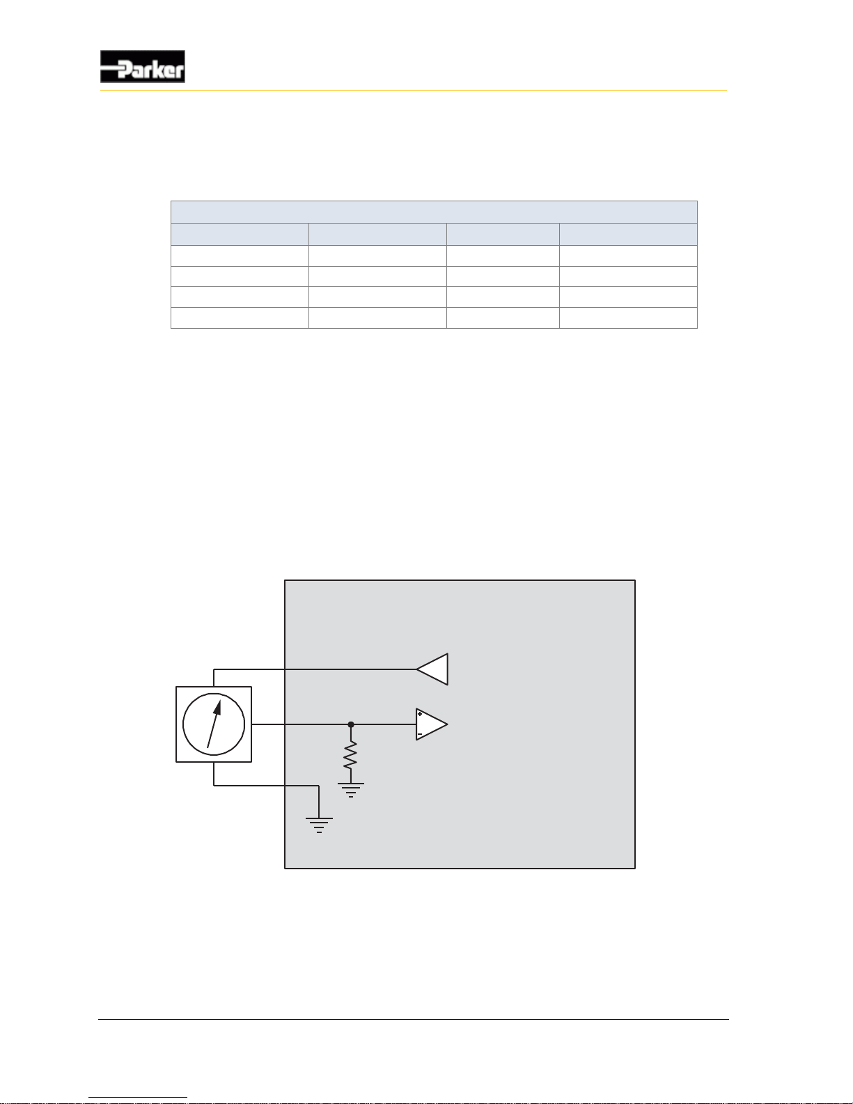
The following shows how to connect an analog input to reduce system noise:
Internal to product
+5 Vdc Sensor Supply
Sensor Ground
Sensor
Analog Input
Figure 4: Analog input system noise reduction
Page 25
User Guide 15
Inputs
Ground level shift
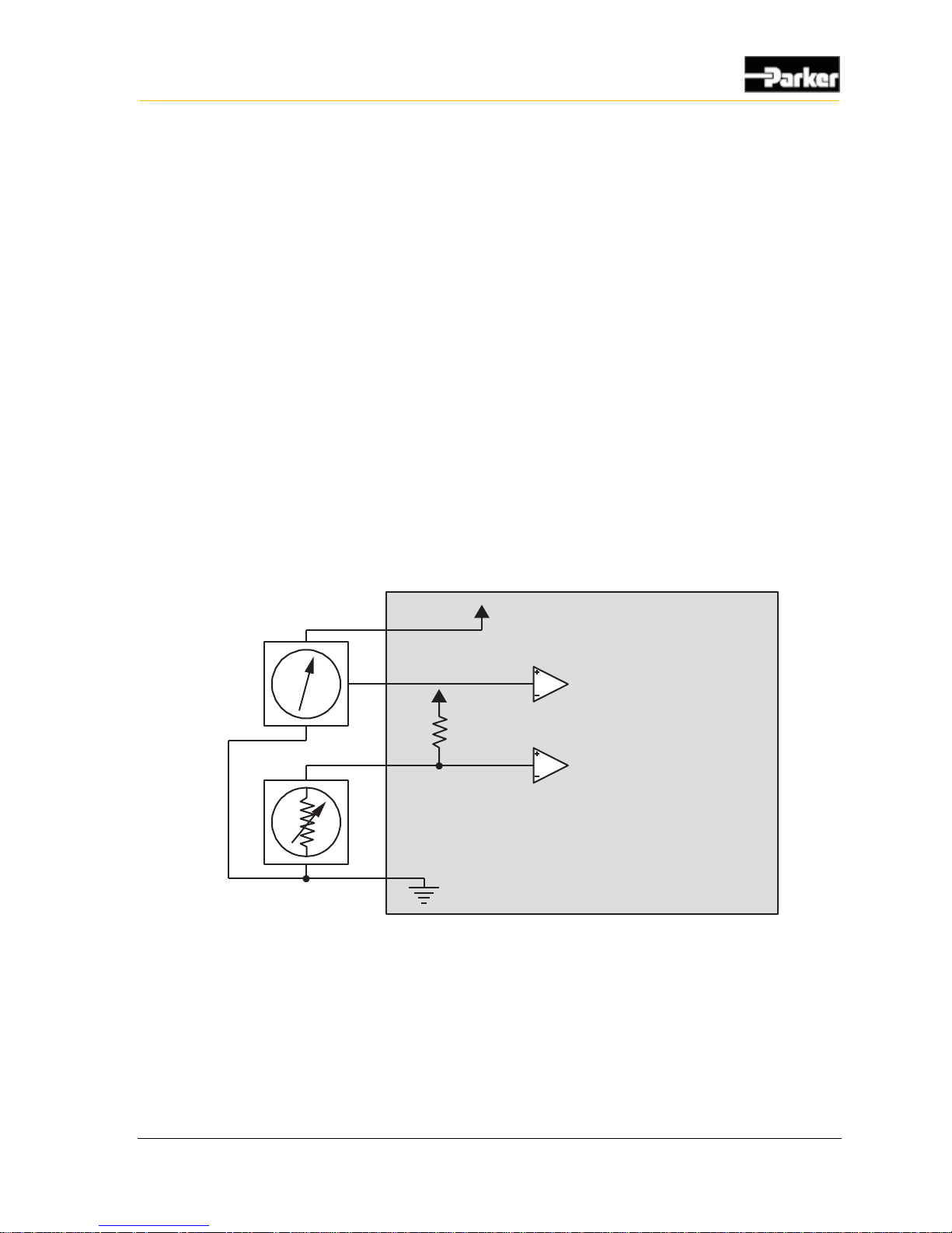
To reduce ground level shift:
1. Dedicate one of the 4 system ground inputs (GND) to sensors that have
dedicated ground wires, and connect all sensor grounds to this system ground
input.
2. Splice the other system ground inputs together in the vehicle harness (close to
the connector) to provide a better ground for the noisier low-side outputs and
digital circuits.
3. Position the sensor’s ground connection near the system ground connections
to ensure that the signal remains within the digital activation range of the
input.
Note 1: The system ground inputs are rated for low-current signals, which
ensures the sensor's ground is very close in voltage potential to the system
ground.
Note 2: Sensors that don’t have a dedicated ground wire are typically
grounded to the vehicle chassis through the sensor’s body.
Internal to product
Sensor Power
Resistive Sensor
Pull-up
Resistor
Active Sensor
Analog Input
Analog Input
Figure 5: Analog input ground shift connection for sensors that have dedicated ground wires
Page 26
16 VMM2404
Inputs
3.1.3. Multi-Purpose Used as AC-Coupled Frequency Input
The following multi-purpose inputs can be used as AC-coupled frequency inputs:
INPUT1_ADF and INPUT2_ADF
3.1.3.1. AC-Coupled Frequency Input Capabilities
AC-coupled frequency inputs provide AC-coupling, which allows you to read the
frequency of external signals that have either large DC offsets, or no ground
reference. These inputs are ideal for use with variable reluctance and inductive
pickup sensors.
Quadrature and pulse counting is possible; however, we recommend that you not
use these functions with AC-coupled frequency inputs.
The following table provides specifications for the VMM2404 general purpose
inputs when used as AC-coupled frequency inputs:
AC-Coupled Frequency Input Specifications
Item
Min
Nom
Max
Unit
Input voltage range6
-90 - 90
V
Pull-up / down resistance
3.1 k
-
3.5 k
Ω
Input resistance – pull-up/pull-down
disabled
81 k - -
Ω
Input capacitance
9
10
11
nF
AC-coupling capacitance
-
0.3
-
uF
Frequency range @ 0.25 Vp-p
5 - 10000
Hz
Accuracy - -
5
%
Resolution
0.1 - -
Hz
Switching threshold voltage7
-
1.65
-
V
Leakage current sleep mode
- pin @ 12 V
- - 4.1
mA
3.1.3.2. AC-Coupled Frequency Input Configuration Options
AC-coupled frequency inputs have 4 programmable gain and attenuation factors.
The pull-up or pull-down resistors for AC-coupled frequency inputs can be
enabled or disabled; however, both pull-up and pull-down cannot be enabled at
the same time. The pull-up and pull-down resistance is 3.3 kΩ.
6
Input voltage range assumes that the inductive pickup will increase in voltage as flywheel speed increases. Analog input pull-
up configuration options must be selected accordingly to prevent damage on those components at these voltage extremes.
7
The switching threshold on AC-coupled inputs is not programmable, and is set internally to ensure proper conversion of the
input signal through a comparator circuit. The value given in the table is not a physical value on the product's input pin.
Page 27

User Guide 17
Inputs
3.1.3.3. AC-Coupled Frequency Input Connections
When connecting AC-coupled frequency inputs, be aware of system noise and
ground level shift.
System Noise
AC-coupled frequency inputs are more susceptible to system noise than digital
inputs.
To reduce system noise:
Connect AC-coupled frequency inputs to sensors with significant DC offset.
Use the shortest possible wires when connecting AC-coupled frequency inputs
to sensors to prevent noise pickup on the sensors.
Ground Level Shift
Ground level shift affects the accuracy of AC-coupled frequency inputs. Ground
level shift refers to the difference between the system ground input (GND)
voltage, and the sensor ground voltage.
To reduce ground level shift:
If there are more than 1 GND pins in the system, dedicate one of them to
sensors that have ground wires, and connect all sensor grounds to that system
ground pin.
Splice the other system ground inputs together in the vehicle harness (close to
the connector), to provide a better ground for the noisier low-side outputs and
digital circuits.
Ensure the sensor’s ground connection is close to the system ground
connections. This will help ensure the signal remains within the digital
activation range of the input.
Note 1: The VMM2404 system ground inputs are rated for low-current
signals, which ensures the sensor’s ground is very close in voltage potential to
the system ground.
Note 2: Sensors that don’t have a dedicated ground wire are typically
grounded to the vehicle chassis through the sensor’s body.
Page 28
18 VMM2404
Inputs
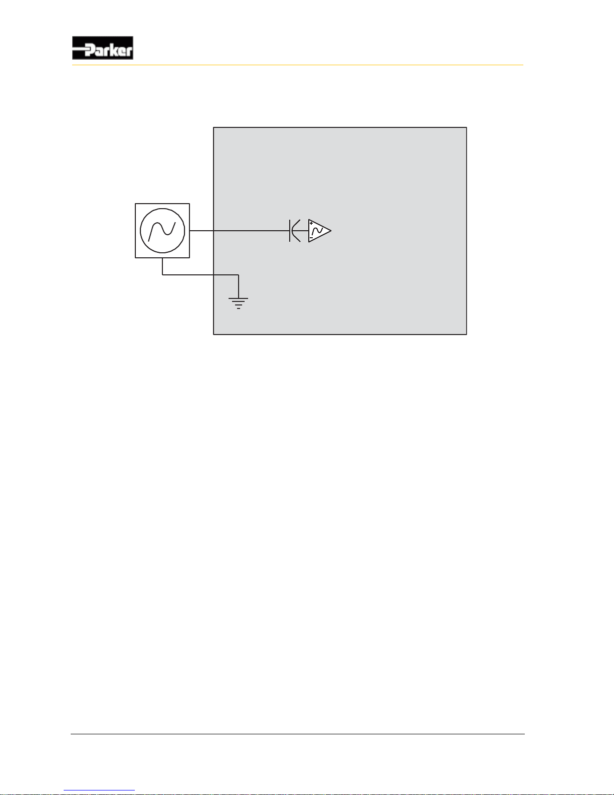
The following shows a typical AC-coupled frequency input connection:
Internal to product
Sensor Ground
Variable Reluctance
Sensor
AC Coupled
Frequency Input
Figure 6: AC-coupled frequency input installation connections
3.1.4. Multi-Purpose Used as DC-Coupled Frequency Input
The following multi-purpose inputs can be used as DC-coupled frequency inputs:
INPUT3_ADF to INPUT_15_ADF
3.1.4.1. DC-Coupled Frequency Input Capabilities
DC-coupled frequency inputs allow you to read the frequency of external signals
that have a ground reference and no DC offset. These inputs are ideal for use with
hall-effect type sensors.
Quadrature and pulse counting is possible with DC-coupled frequency inputs.
Page 29
User Guide 19
Inputs
The following table provides specifications for the VMM2404 general purpose
inputs when used as DC-coupled frequency inputs:
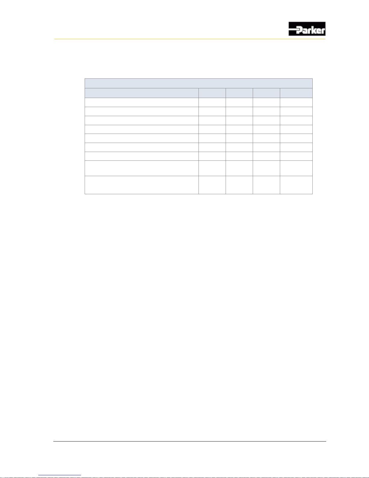
DC-Coupled Frequency Input Specifications
Item
Min
Nom
Max
Unit
Input voltage range
0 - 32
V
Pull-up / down resistance
3.1 k
-
3.5 k
Ω
Input resistance – pull-up/pull-down disabled
81 k - -
Ω
Input capacitance
9
10
11
nF
Frequency range @ 0.25 Vp-p
1 - 10000
Hz
Accuracy
- - 5
%
Resolution
0.1 - -
Hz
Switching threshold voltage (software)
-
Program-
mable
-
V
Leakage current sleep mode
- pin @ 12 V
- - 4.1
mA
3.1.4.2. DC-Coupled Frequency Input Configuration Options
DC-coupled frequency inputs have 4 programmable gain and attenuation factors,
as indicated in Table 3.
The pull-up or pull-down resistors for DC-coupled frequency inputs can be
enabled or disabled; however, both pull-up and pull-down cannot be enabled at
the same time. The pull-up and pull-down resistance is 3.3 kΩ.
3.1.4.3. DC-Coupled Frequency Input Connections
When connecting DC-coupled frequency inputs, be aware of system noise and
ground level shift.
System Noise
DC-coupled frequency inputs are more susceptible to system noise than digital
inputs.
Page 30

20 VMM2404
Inputs
To reduce system noise:
Connect DC-coupled frequency inputs to sensors that produce signals with no
DC offset.
Use the shortest possible wires when connecting DC-coupled frequency inputs
to sensors to prevent noise pickup on the sensors.
Ground Level Shift
Ground level shift affects the accuracy of DC-coupled frequency inputs. Ground
level shift refers to the difference between the system ground input (GND)
voltage, and the sensor ground voltage.
To reduce ground level shift:
If there are more than 1 GND pins in the system, dedicate one of them to
sensors that have ground wires, and connect all sensor grounds to that system
ground pin.
Splice the other system ground inputs together in the vehicle harness (close to
the connector), to provide a better ground for the noisier low-side outputs and
digital circuits.
Ensure the sensor’s ground connection is close to the system ground
connections. This will help ensure the signal remains within the digital
activation range of the input.
Note 1: The VMM2404 system ground inputs are rated for low-current
signals, which ensures the sensor’s ground is very close in voltage potential to
the system ground.
Note 2: Sensors that don’t have a dedicated ground wire are typically
grounded to the vehicle chassis through the sensor’s body.
Page 31
User Guide 21
Inputs
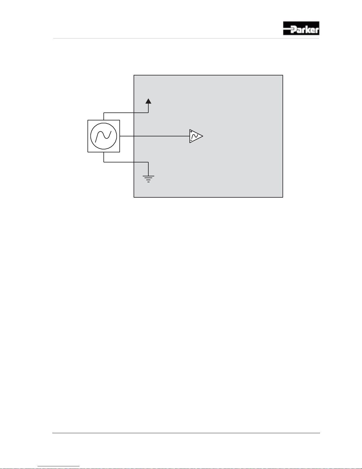
The following shows a typical DC-coupled frequency input connection:
Internal to product
Sensor Voltage
Sensor Ground
Hall Effect Sensor
DC Coupled
Frequency Input
Figure 7: DC-coupled frequency input installation connections
3.2. Digital Inputs
Digital inputs are typically used with electrical signals and switches that are either
on or off.
There are three types of digital inputs in the VMM2404:
Programmable Digital Inputs
Power Control Digital Inputs
Addressing Digital Inputs
3.2.1. Programmable Digital Inputs
The VMM2404 has 9 programmable digital inputs:
INPUT16_D through INPUT24_D.
The general purpose inputs can also be used as programmable digital inputs.
Page 32
22 VMM2404
Inputs
3.2.1.1. Programmable Digital Input Installation Connections
A digital input is typically connected to a switch that is either open or closed.
When the switch is open, the pull-up or pull-down resistor will ensure that no
signal exists on the input pin, which will be interpreted by the VMM2404 as
inactive.
When the switch is closed, the input is connected to either battery voltage or
ground, which will be interpreted by the VMM2404 as active.
Active-high input
The active-high output must be connected to battery power to ensure that there is
a battery connection when the state of the input changes.
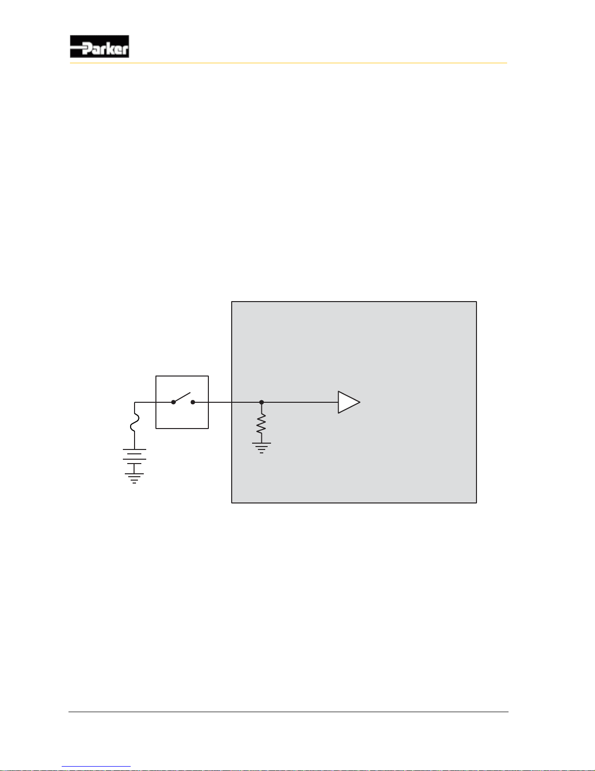
The following shows a typical active-high digital input connection:
Internal to product
Active High
Digital Input
Battery
Application Switch
Figure 8: Active high digital input
Page 33
User Guide 23
Inputs
Active low input
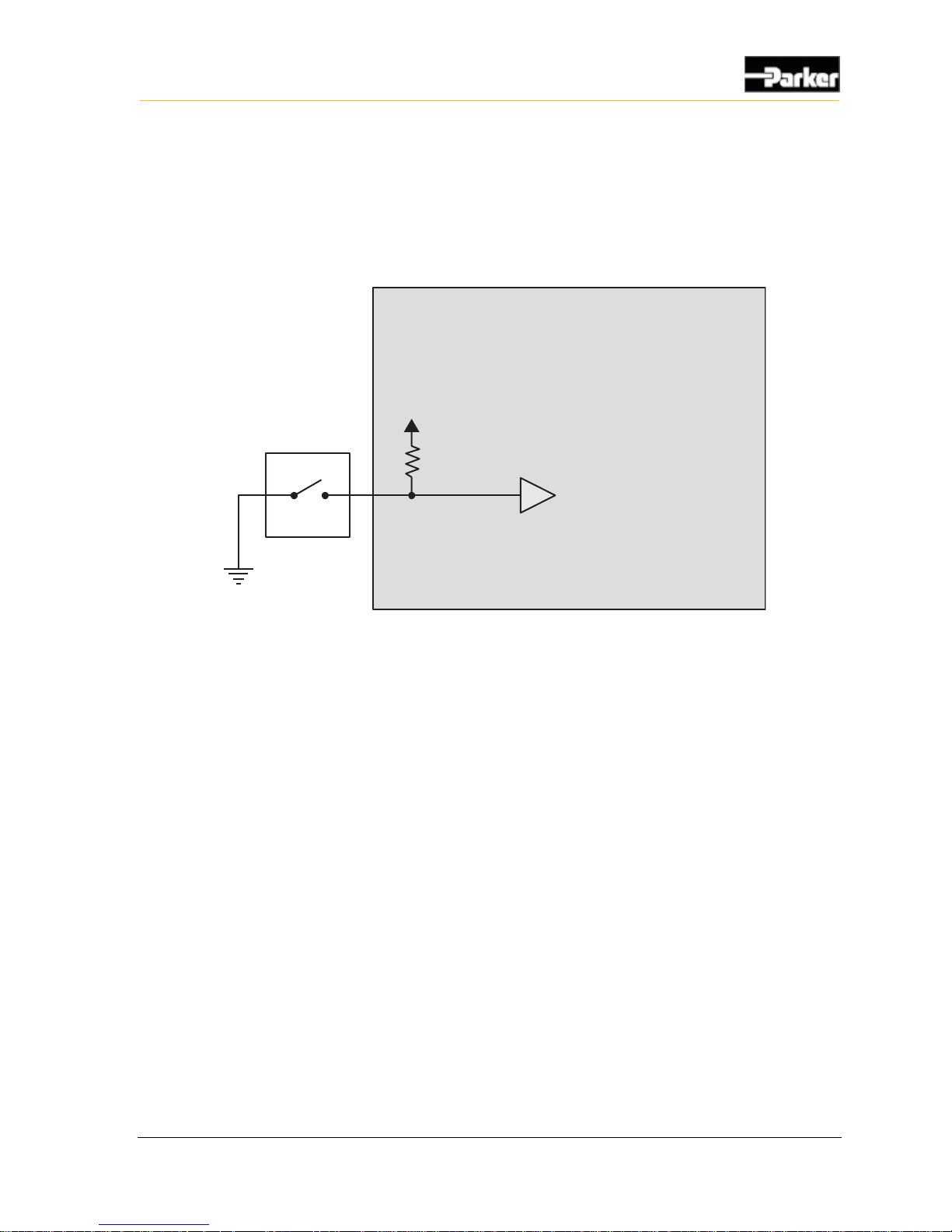
The active-low input must be connected to ground to ensure there is a ground
connection when the state of the input changes.
The following shows a typical active-low digital input connection:
Internal to product
Application switch
Active Low
Digital Input
Figure 9: Active low digital input connections
3.2.2. Power Control Digital Inputs
The VMM2404 has 1 active high digital input dedicated to power control that is
used for waking up (turning on) the product, called POWER_CONTROL.
3.2.2.1. Power Control Digital Input Capabilities
The VMM2404 has an active high power control digital input that must be
activated to power up the VMM2404.
Note: The power control digital input voltage must be greater than 4.0 V
before it is considered an active high input.
The power control digital input wakes-up the VMM2404 when switched high to a
voltage of 4.0 V or greater, and puts the VMM2404 in sleep mode (turns it off)
when switched low to a voltage less than 1.7 V. The VMM2404 will also go into
sleep mode when an open circuit condition occurs on the power control digital
input.
Page 34
24 VMM2404
Inputs
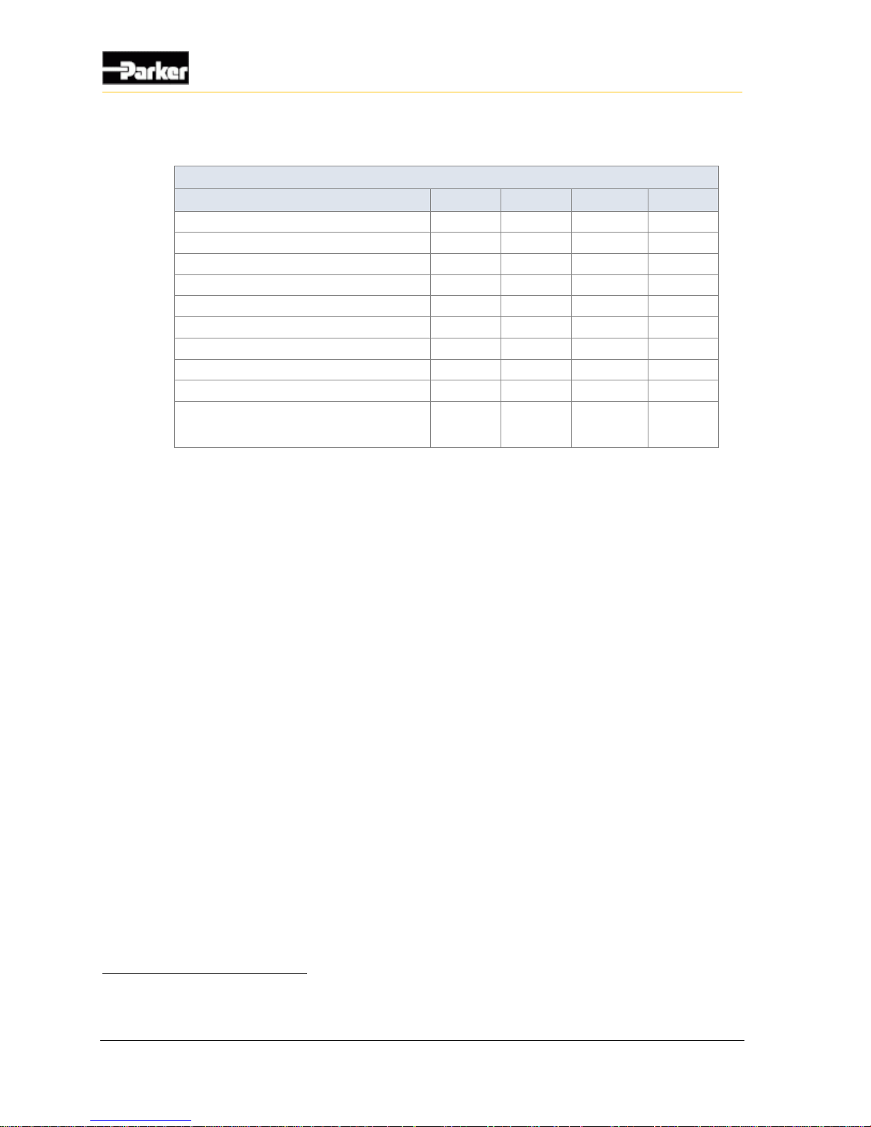
The following table provides specifications for the power control digital input:
Power Control Digital Input Specifications
Item
Min
Nom
Max
Unit
Input voltage range
0 - 32
V
Pull-down resistance
3.1 k - 3.5 k
Ω
Minimum negative going threshold
2.14 - -
V
Maximum positive going threshold
- - 4.0
V
Power-up threshold
-
1.7
-
V
Cutoff frequency (hardware)8
-
85
-
Hz
De-bounce time (software)9
25 - 50
ms
Overvoltage
- - 36
V
Wetting current @ 12 V
3.43 - 3.87
mA
Leakage current sleep mode
- battery @ 12 V
- - 200
uA
3.2.2.2. Power Control Digital Input Installation Connections
You must be aware of the following when connecting the power control digital
input:
The power control digital input is usually connected to the vehicle ignition,
but it can be connected to any power source in a system.
To protect the harness that connects the VMM2404 to the ignition, place a
fuse of 200 mA or higher in the circuit that feeds the VMM2404.
If your VMM2404 must always be powered, the power control digital input
can be directly connected to a fused battery power input (called VBATT),
which will provide constant power.
When battery power (VBATT) is connected, and the power control digital
input is inactive, the VMM2404 will go into sleep mode.
8
Assumes there is a zero ohm source impedance from driving source. The actual cutoff in the application will be partially
determined from the source impedance and VMM input capacitance.
9
De-bounce time is based on a sampling rate of 40 Hz.
Page 35
User Guide 25
Inputs
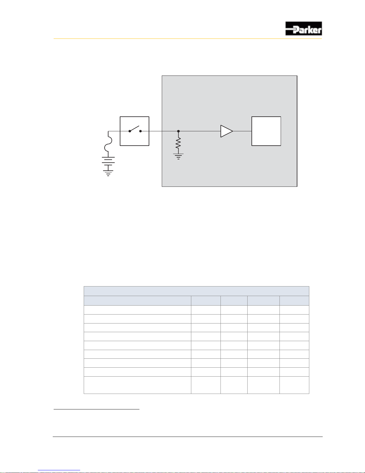
The following shows a typical power control digital input connection:
Internal to product
Power Control Input
Power
Control
Pull-Down
Resistor
Battery
Fuse Min.
200 mA
Application Switch
Figure 10: Power control digital input installation connections
3.2.3. Addressing Digital Inputs
The VMM2404 has 5 active low digital inputs that are used for module
addressing on the CAN network:
ADDR1 to ADDR5
3.2.3.1. Addressing Digital Input Capabilities
The following table provides specifications for the VMM2404 addressing digital
inputs:
Addressing Digital Input Specifications
Item
Min
Nom
Max
Unit
Input voltage range
0 - 32
V
Overvoltage
- - 36
V
Pull-up resistance
9.8 k - 10.2
kΩ
Minimum negative going threshold
0.9 - -
V
Maximum positive going threshold
- - 2.15
V
Cutoff frequency (hardware)
-
80
-
Hz
De-bounce time10
- - -
ms
Wetting current
316 - 343
uA
Leakage current sleep mode
- pin grounded or floating
- 0 -
A
10
De-bounce time for address inputs is based on hardware cutoff frequency. The software reads the address in succession
during power-up until it receives two consecutive results that are the same. The time between readings is in the microsecond
range so there is technically no software de-bounce on these inputs.
Page 36
26 VMM2404
Inputs
3.2.3.2. Addressing Digital Input Connections
These inputs are used to set the system address on the module such that it is
unique among all other modules in the system. The maximum allowable addresses
in a VMM system is 31.
The inputs are all active low inputs with internal pull-up resistors. The inputs are
pulsed to ensure that a floating pin is read as inactive by the module.
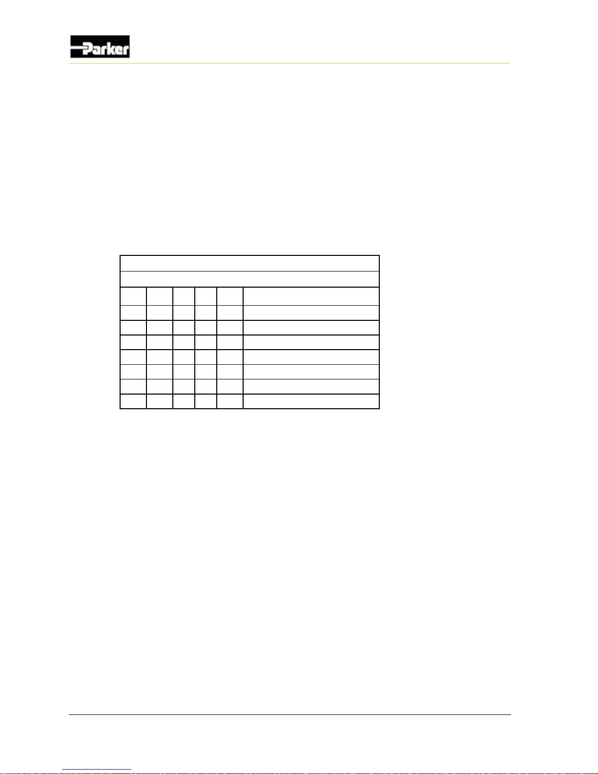
The addressing arrangement is shown in the following table, which shows the
required inputs that need to be active (connected to ground), and those that are
floating.
VMM system addressing (active=1, floating=0)
Address Inputs
5 4 3 2 1
VMM address
0 0 0 0 0
VMM1
0 0 0 0 1
VMM2
0 0 0 1 0
VMM3
0 0 0 1 1
VMM4
0 0 1 0 0
VMM5 | | | | | | 1 1 1 1 0 VMM31
Note: Address 32 is reserved and therefore may not be used in a system
design.
Page 37
User Guide 27
Inputs
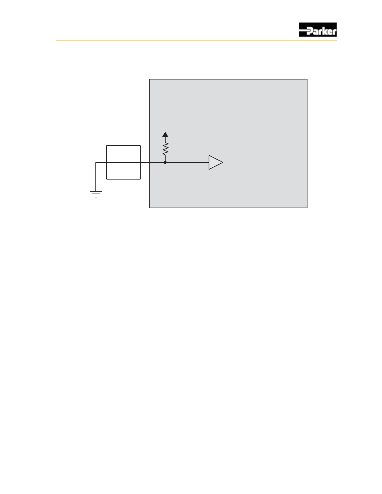
The following shows a typical active low digital input addressing connection:
Internal to product
Customer
connection
Addressing
Digital Input
Figure 11: Addressing digital input connections
Page 38

28 VMM2404
Outputs
The VMM2404 has 8 solid-state FET technology outputs designed for low to
medium current and high inrush inductive load switching. Output currents can
range up to 3.0 A.
The VMM2404 has 2 types of outputs:
High-side outputs
Low-side outputs with current sense
Note: A high-side and a low-side output can be used to create a half-bridge.
An H-bridge output can be created from 2 half-bridges, allowing 2 full Hbridge outputs to be produced (refer to Controlling a Linear Actuator for an
example of how to use an H-bridge).
4.1. High-side outputs
The VMM2404 has 4 high-side outputs:
OUTPUT1_3A_HS to OUTPUT4_3A_HS
4.1.1. High-Side Output Capabilities
High-side outputs are used for switching voltages to loads using either a pulse
width modulated (PWM) signal, or an on/off signal. They can also test for various
fault conditions, which can be used for software diagnostics (see High-Side
Output Diagnostics and Fault Protection for more details).
All high-side outputs come with internal flyback diodes that provide protection
when driving inductive loads.
When a high-side output is used as a PWM signal, a pulsed output signal is
provided by the VMM2404, where the percentage of time that the output is
“on” vs. “off” is determined by the duty cycle of the signal, and the duty cycle
is determined by the application software.
When a high-side output is used as an on/off signal, the output provides
battery voltage when in the “on” state (the application software is responsible
for switching high-side outputs On and Off).
4. Outputs
Page 39

User Guide 29
Outputs
High-Side Output Specifications
Item
Min
Nom
Max
Unit
Operational voltage range
6 - 32
V
Overvoltage
- - 36
V
Output current range
0 - 3
A
Load impedance @ 12 V
4 - -
Ω
PWM frequency
5 - 500
Hz
PWM resolution11
-
0.1
-
%
Flyback diode current12
- - 1
A
Short-circuit current limit
(Tjunc = -40ºC to +150ºC)
9
15
23
A
Short-circuit trip time
- 2 -
ms
Thermal protection
-
150
-
ºC
Digital feedback negative threshold
1.5 - -
V
Digital feedback positive threshold
- - 3.58
V
Digital feedback cutoff frequency
-
26
-
kHz
Open-load detection – max detectable load
@ 12 V
- - 1.4 k
Ω
Open-load detection pull-up
9.8 k - 10.2
kΩ
Current sensing
-
No
-
-
Analog feedback
-
No
-
-
4.1.2. High-Side Output Installation Connections
When connecting high-side outputs, note that
High-side outputs are connected to an internal bus bar, which is connected to
the battery. The bus bar is also connected to logic power (VBATT), and both
share the same connector pins.
High-side outputs can provide switched battery power to any load type in a
vehicle.
High-side outputs can source up to 3.0 A max.
High-side outputs have internal flyback diodes, which are needed when
driving inductive loads (the flyback diodes absorb electrical energy when the
load is turned off).
Inductive loads will create an average current flow that moves out of the high-side
output. When the output is on, the current flows through the output driver, and
when the output is off, the current flows through the flyback diode. A duty cycle
11
This is the typical value. Actual value is dependent on the base frequency, since the counter used for this operation has a
finite number of steps.
12
This is an average current value, meaning a worst case PWM current of 2 A at 50% duty cycle is possible with inductive
loads.
Page 40
30 VMM2404
Outputs
of 50% will produce the worst case average current flow through these two
devices.
Note: If large inductive loads are used, and the high-side output is providing a
continuous PWM signal, the PWM peak current must not be greater than the
specified continuous current for the output (in continuous mode, the average
current flow through the diode at 50% duty cycle is approximately equal to ½
the peak current).
When connecting high-side outputs, ensure you follow these best practices:
High-side outputs should not be connected to loads that will draw currents
greater than the maximum peak current, or maximum continuous current.
The grounds for the loads should be connected physically close to the
VMM2404 power grounds.
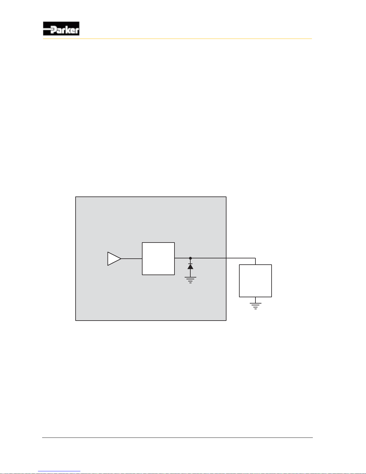
The following shows a typical high-side output connection:
Internal to product
High-Side
Output
Application
Load
Figure 12: Typical high-side output installation connections
4.1.3. High-Side Output Diagnostics and Fault Protection
The VMM2404 high-side outputs have the ability to report many different fault
conditions. They are protected against short-circuit and overcurrent, open load,
and short-to-battery faults.
Note: The VMM2404 LEDs can be used to indicate output fault status
through the application software.
Page 41

User Guide 31
Outputs
4.1.3.1. Short Circuit
Short-circuit faults occur when a high-side output pin is shorted to ground. Refer
to the VMM2404 Platform Framework API document distributed with the SDK
for details on how to recover from a short circuit.
4.1.3.2. Open Load
Open load faults occur when a low-side output pin is open circuit (not connected
to a load). The use of this feature operates is defined in the VMM2404 Platform
Framework API document distributed with the SDK.
Note: Low-side outputs must be on to detect an open-load fault.
4.1.3.3. Short-to-Battery
Short-to-battery faults occur when a high-side output pin is connected to battery
voltage.
The high-side output circuit uses voltage on the output pin to determine if a shortto-battery condition exists.
Note: To detect a short-to-battery fault, high-side outputs must be off.
4.2. Low-Side Outputs with Current Sense
The VMM2404 has 4 low-side outputs:
OUTPUT5_3A_LS to OUTPUT8_3A_LS
4.2.1. Low-Side Outputs with Current Sense Capabilities
Low-side outputs with current sense are used for switching grounds to loads using
either a pulse width modulated (PWM) signal, or an on/off signal. They also have
the ability to sense current that is provided to loads, through an amplifier circuit.
When a low-side output is used as a PWM signal, a pulsed output signal is
provided by the VMM2404, where the percentage of time that the output is
“on” vs. “off” is determined by the duty cycle of the signal, and the duty cycle
is determined by the application software.
Note: Current flow gets interrupted when using low-side outputs as a PWM
signal, because the outputs are not On continuously. Therefore, current
feedback control systems should use a high-side output for PWM signals, and
a low-side output (turned on at 100%) for sensing current.
Page 42

32 VMM2404
Outputs
When low-side outputs are used as an on/off signal, the output provides
ground when in the “on” state (the application software is responsible for
switching low-side outputs On and Off).
When low-side outputs are used to sense current, the application software will
monitor the current flowing into the low-side output, and based on the amount
of current, will turn the output either On or Off.
The amplifier that measures the sensed current has an allowable voltage
range of 0 V to 3 V. The application software will protect the circuit from
an overcurrent or short-circuit event when the voltage from the amplifier
reaches 2.9 V; therefore, the actual usable voltage range from the
amplifier is only 0 V to 2.8 V.
The following table provides specifications for the VMM2404 low-side outputs:
Low-Side Outputs with Current Sense Specifications
Item
Min
Nom
Max
Unit
Operational voltage range
0 - 32
V
Overvoltage
- - 36
V
Output current range
0 - 3
A
Load impedance @ 12 V
- 4 -
Ω
PWM - No
-
-
Short-circuit protection
-
Yes
-
-
Thermal protection
-
No
-
-
Analog feedback gain
(current sense) - programmable
6.008
(0.6)
Program-
mable
10
(1)
V/V
(V/A)
Analog feedback cutoff frequency @ min gain
-
12
-
Hz
Current sense resistance
0.099
-
.101
Ω
Current sensing resolution -
0 to 3 A range
- 5 14.5
mA
Current sensing resolution -
0 to 2 A range
- 3 8.7
mA
Current sensing accuracy
- - 3.5
%
Short-circuit trip time
- - 500
us
Short-circuit current limit
-
14
-
A
Overcurrent trip point -
0 to 3 A range
-
3.1
-
A
Overcurrent trip point -
0 to 2 A range
-
2.1
-
A
Overcurrent trip time
- 1 -
s
Open-load detection
-
No
-
-
Digital feedback
-
No
-
-
Page 43
User Guide 33
Outputs
4.2.2. Low-Side Outputs with Current Sense Configuration
Options
There are two programmable gain and attenuation factors that allow you to
convert the maximum voltage expected on the low-side outputs to as close to 3.0
V as possible (to optimize the voltage resolution).
Gain and Attenuation for Low-Side Outputs with Current Sense
Amp Gain
Max Current (A)
Attenuation 1
Gain 1
6.008
5
ON
ON
10 3 OFF
OFF
4.2.3. Low-Side Outputs with Current Sense Installation
Connections
When connecting low-side outputs, note that
Low-side outputs are connected to a common internal ground point that is
connected to the battery ground (GND).
Low-side outputs provide switched ground to any load type in a vehicle.
Low-side outputs can sink up to 3.0 A.
When connecting a load to a low-side output, ensure the load will not drive
currents greater than the maximum specified peak current, or maximum
specified continuous current.
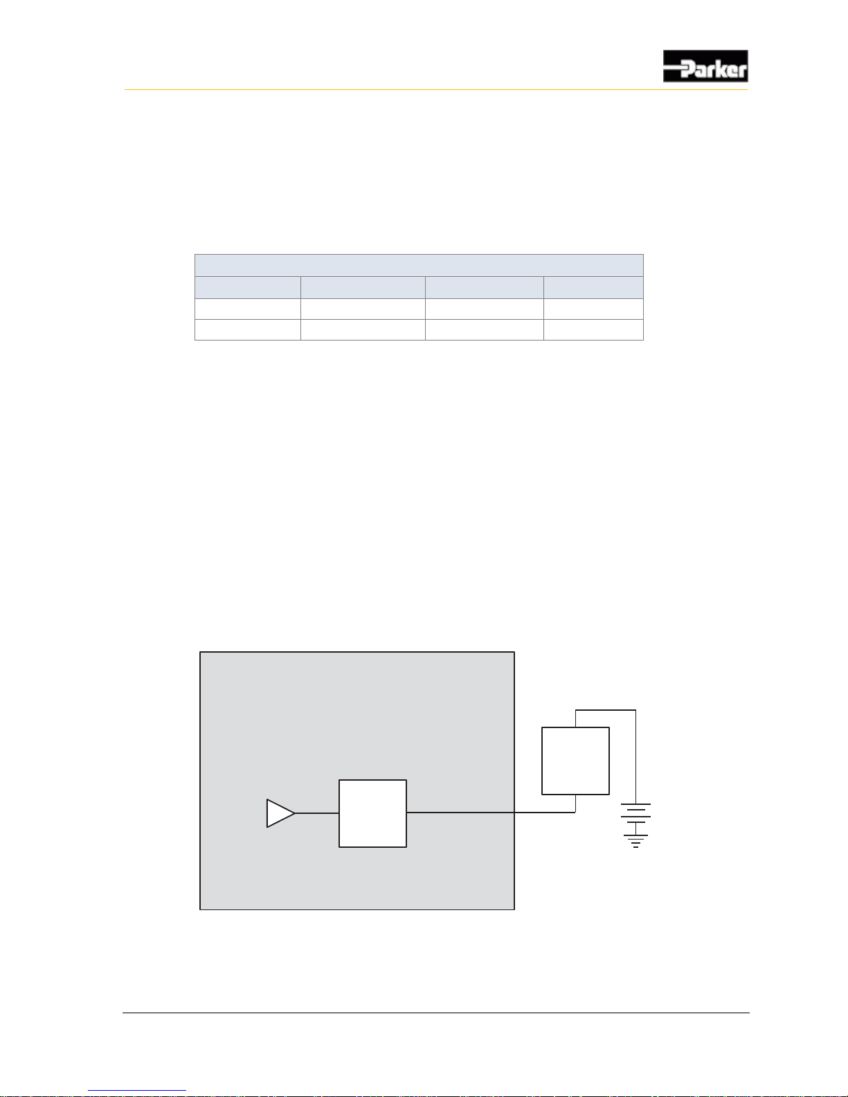
The following shows a typical low-side output connection:
Internal to product
Low-Side
Output
Application
Load
Battery
Figure 13: Typical low-side output connection
Page 44

34 VMM2404
Outputs
4.2.4. Low-Side Outputs with Diagnostics and Fault
Protection
The VMM2404 low-side outputs have the ability to report many different fault
conditions, and are protected against short-circuit, overcurrent, and short-toground faults.
Note: The VMM2404 diagnostic LEDs indicate the output's status.
4.2.4.1. Short-Circuit
Short circuit faults occur when a low-side output pin is shorted to battery. For
details on how to recover from a short circuit refer to the VMM2404 Platform
Framework API document distributed with the SDK.
4.2.4.2. Overcurrent
Overcurrent faults occur when a low-side output pin draws more current than the
specified overcurrent trip point.
When an overcurrent fault is detected, the hardware automatically turns off the
output.
The overcurrent trip time for low-side outputs is approximately 1 second.
Note: The VMM2404 can be programmed to automatically reset an output
from an overcurrent fault.
4.2.4.3. Short-to-Ground
Short-to-ground faults occur when a low-side output pin is connected to ground.
The low-side output circuit uses current on the output pin to determine if a short-
to-ground condition exists.
Page 45

User Guide 35
Power
The VMM2404 is powered by the vehicle battery. The VMM2404 operates in a
12 V or 24 V system, and can operate from 6 V up to 32 V, with over-voltage
protection at 36 V.
The various pins on the connectors are used for different types of power, as
detailed in the following sections.
5.1. Logic and output power
The VMM2404 has 3 pins, labeled VBATT, dedicated to providing power for
logic and outputs, and 4 pins, labeled GND, dedicated to grounding the
VMM2404.
Note: The power and ground connections are usually paralleled over several
pins to minimize voltage drops on higher current applications.
5.1.1. Logic and Output Power Capabilities
Logic power provides power to the logic circuit, which consists of the
microprocessor, RAM, etc. The logic circuit can draw a maximum of 300 mA.
Output power provides power to the output circuits through a battery or ground
connection. Each output circuit can draw a maximum of 3 A.
5. Power
Page 46
36 VMM2404
Power
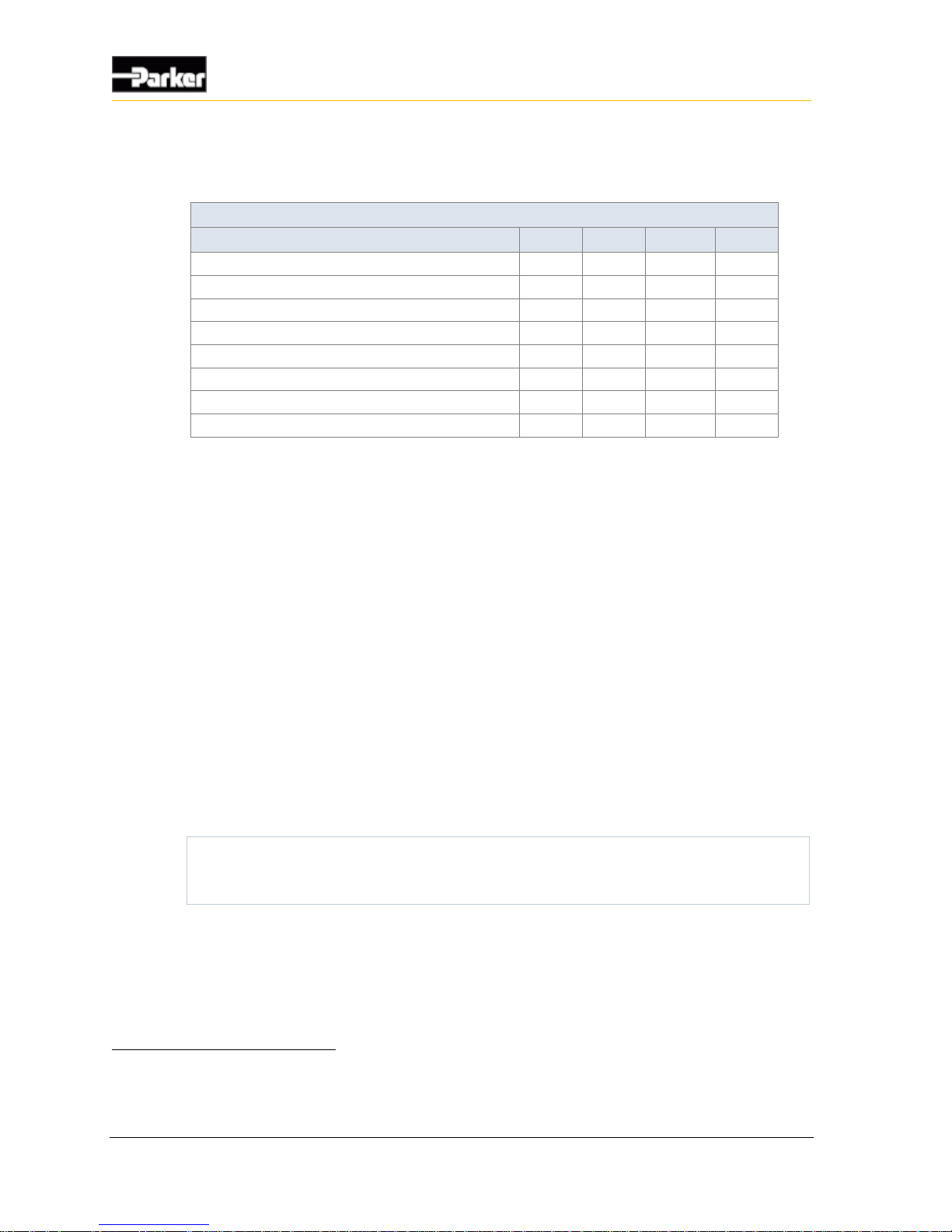
The following table provides specifications for the VMM2404 logic and output
power:
Logic and Output Power Specifications
Item
Min
Nom
Max
Unit
Input voltage range
6 - 32
V
Overvoltage
- - 36
V
Current draw in on state (excluding outputs)
- - 300
mA
Current draw in on state (including outputs)
- - 13
A
Current draw in sleep mode13
- - 1
mA
Inline fuse required on power pins (ATO style)14
-
25
-
A
Number of power pins
- 3 -
-
Number of ground pins
- 4 -
-
5.1.2. Logic and output power connections
When connecting the VMM2404 logic and output power, note that:
Logic and output power connections are made using the VBATT and GND
pins.
When there are multiple output power pins, the number of wires needed to
connect the VMM2404 power depends on the amount of current required by
the application.
It is recommended that you use the largest AWG wire allowed by your
connector for the VBATT and GND pins, to meet the amount of expected
output current; however, this is not always true and depends on your
application.
The VMM2404 is protected against reverse-battery connections by an internal
high-current conduction path that goes from ground to power. To protect the
VMM2404 from damage in a reverse-battery condition, place a fuse of 25 A
or less in series with the power wires in the application harness.
Select fuse sizes by multiplying the maximum continuous current during normal
operation by 1.333 (75% de-rating factor). Do not use slow-blow fuses for this
application.
All power connections to the VMM2404 should be fused to protect the vehicle
harness.
13
Assumes there is no current flow through input or output connections in harness. Either active high inputs are not connected
to battery during sleep mode, or active-low inputs are not connected to ground during sleep mode.
14
This is required to ensure proper reverse battery protection on the module. Failure to include this fuse in the end application
harness could result in damage to the module and/or the application harness.
Page 47
User Guide 37
Power
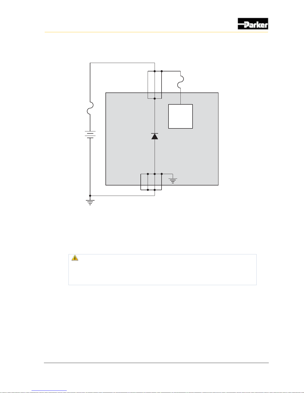
The following shows a typical logic and output power connection:
Internal to product
ReverseBattery
Protection
Power
Control
Ground Pins
Battery
Fuse Max
25 A
Power Pins
Fuse Min
200 mA
Figure 14: Logic and output power installation connections
5.2. Sensor supply
The VMM2404 has one pin, labeled SENSOR_SUPPLY, dedicated to providing
power to external sensor.
Warning! Do not drive more than 100 mA of current through the
SENSOR_SUPPLY pin. Doing so will cause the pin to protect itself by
dropping the voltage, which will result in a lack of power to the sensors,
causing unknown vehicle responses.
5.2.1. Sensor Power Capabilities
SENSOR_SUPPLY is a 5V linear power supply that is capable of continuously
providing up to 100mA to external sensors.
Page 48
38 VMM2404
Power
Note: The voltage provided to the VMM2404 must be 6.5 V or greater to
ensure the sensor supply can provide 5 V.
Depending on system voltage, SENSOR_SUPPLY is capable of delivering different
amounts of current to the sensors, as detailed in the following table:
Maximum Sensor Current at Various Voltages
Input Voltage
Maximum Sensor Current
6.5–14 VDC
100 mA
14–24 VDC
50 mA
24–32 VDC
30 mA
The following table provides specifications for the VMM2404 sensor power:
Sensor Power Specifications
Item
Min
Nom
Max
Unit
Input voltage range
6.5 - 32
V
Overvoltage
- - 36
V
Output voltage range
4.8 5 5.2
V
Output voltage accuracy
- 4 -
%
Output current (linear) @ 6.5 to 14 V battery
0 - 100
mA
Output current (linear) @ 14 to 24 V battery
0 - 50
mA
Output current (linear) @ 24 to 32 V battery
0 - 30
mA
Number of sensor power connector pins
- 1 -
-
5.2.1.1. Sensor Power Fault Responses
SENSOR_SUPPLY is designed to survive short-to-battery, short-to-ground, and over-
current events. If these events occur, the circuit will recover as described in the
following table:
Sensor Power Fault Recovery
Event
Recovery
Short-to-battery
(sensor voltage = battery voltage)
Sensor voltage recovers when the short is removed.
Short-to-ground
(sensor voltage = ground)
Sensor voltage recovers when the short is removed.
Over-current
(sensor voltage = ground)
Sensor voltage recovers when the over-current
condition is removed.
5.2.2. Sensor Power Connections
For information on how to connect sensors, refer to Application Examples on
page 51.
Page 49
User Guide 39
Communication
The only type of communication available to the VMM2404 is Controller Area
Network (CAN) communication.
6.1. Controller area network
The VMM2404 has 1 Controller Area Network (CAN) communication port(s)
available. The VMM2404 hardware provides controller area network (CAN)
communication according to the SAE J1939 specification, making the VMM2404
compatible with any CAN-based protocol through software.
CAN communication is used to communicate the status of multiple modules that
are connected together in the same network.
6.1.1. J1939 CAN Capabilities
The CAN communicates information at a rate of 250 kbps. VMM2404 input and
output information is transmitted through the CAN at a broadcast rate of 40 Hz.
Lack of regular CAN communication is an indication that there is either a
problem with a module in the network, or a problem with the CAN bus.
The following table provides specifications for the CAN:
Item
Min
Nom
Max
Unit
Max voltage
- - 32
V
Onboard terminator option
-
No
-
Wake on CAN option
-
No
-
Baud rate
-
250
-
kbps
J1939 compliant
-
Yes
-
6.1.2. J1939 CAN Installation Connections
The CAN connection for the VMM2404 should conform to the J1939 standard.
The J1939 standard is a robust automotive specification that is a good CAN
installation guideline even when the J1939 CAN protocol is not being used.
6. Communication
Page 50

40 VMM2404
Communication
For a list of J1939 connection considerations, refer to the SAE J1939
specifications available through the Society for Automotive Engineers. SAE
J1939-11 covers the physical aspects of the CAN bus including cable type,
connector type, and cable lengths.
Note: The standard variant of the VMM2404 does not have a CAN
termination resistor, which is based on the assumption that the CAN bus is
terminated in the harness.
The following lists the elements that are required for a J1939 CAN connection:
CAN Cable: A shielded twisted-pair cable should be used when connecting
multiple modules to the CAN bus. The cable for the J1939 CAN bus has three
wires: CAN High, CAN Low, and CAN Shield (which connect to the
corresponding CAN_HIGH, CAN_LOW, and CAN_SHIELD pins on the
connector). When a module does not have a CAN_SHIELD pin, the CAN
Shield should be connected to an available ground terminal attached to the
negative battery. The CAN cable must have an impedance of 120 Ω.
The CAN cable is very susceptible to system noise; therefore, CAN shield
must be connected as follows:
a. Connect CAN Shield to the point of least electrical noise on the CAN bus.
b. Connect CAN Shield as close to the center of the CAN bus as possible.
c. Use the lowest impedance connection possible.
Note: Ground loops can damage electronic modules. The CAN Shield can
only be grounded to one point on the network. If grounded to multiple points,
a ground loop may occur.
CAN Connectors: Industry-approved CAN connectors are manufactured by
ITT Cannon and Deutsch, and come in either T or Y configurations.
CAN Harness: The CAN harness is the main backbone cable that is used to
connect the CAN network. This cable cannot be longer than 40 meters and
must have a 120 Ω terminating resistor at each end. The 120 Ω terminating
resistors eliminate bus reflections and ensure proper idle-state voltage levels.
CAN Stubs: The CAN stubs cannot be longer than 1 meter, and each stub
should vary in length to eliminate bus reflections and ensure proper idle state
voltage levels.
Max Number of Modules in a System: The CAN bus can handle a maximum
of 30 modules in a system at one time.
Page 51
User Guide 41
Communication
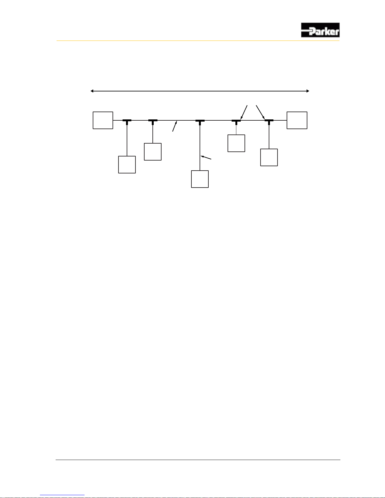
The following shows a typical CAN connection using the SAE J1939 standard:
120 ohm
Terminator
120 ohm
Terminator
Node
Node
Node
Node
Node
T connectors
Variablelength
CAN stub (<1m)
CAN Network Backbone
(less than 40 meters long)
Figure 15: J1939 CAN connection
Page 52
42 VMM2404
Diagnostic LEDs
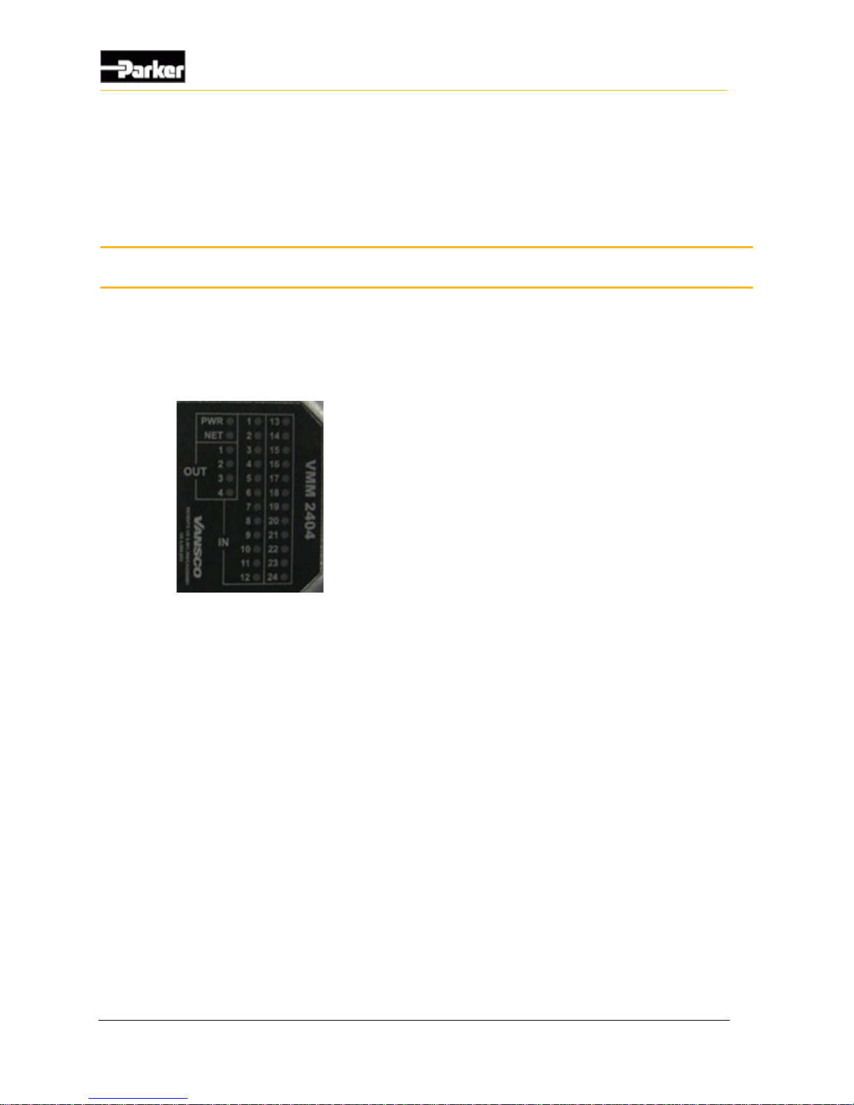
The VMM2404 has 30 red LEDs that are used to indicate the status of inputs,
outputs, power and the Controller Area Network (CAN).
The following shows the VMM2404's LEDs as they appear on the product:
Figure 16: VMM2404 LEDs
7.1. Input LEDs
Input LEDs are used to indicate the status of inputs.
Input LEDs are labeled “IN” (1 to 24) on the VMM2404.
7.2. Output LEDs
Output LEDs are used to indicate the status of high-side outputs.
Output LEDs are labeled “OUT” (1 to 4) on the VMM2404.
7.3. Power LED
The power LED (labeled PWR) is used to indicate the status of power, software,
and faults on the VMM2404.
7. Diagnostic LEDs
Page 53

User Guide 43
Diagnostic LEDs
7.4. Network LED
The network LED (labeled NET) is used to monitor the state of the CAN network.
Page 54
44 VMM2404
Connectors
The VMM2404 has two Ampseal connectors, as follows:
One 35-pin connector – Black (J1): AMP 776164-1.
One 23-pin connector – Black (J2): AMP 770680-1.
Both connectors have pins that connect to inputs, outputs, power, and the
Controller Area Network (CAN). Each connector has unique keying that prevents
you from incorrectly mating the connectors to the vehicle harness. The vehicle
harness should be designed to interface with both connectors.
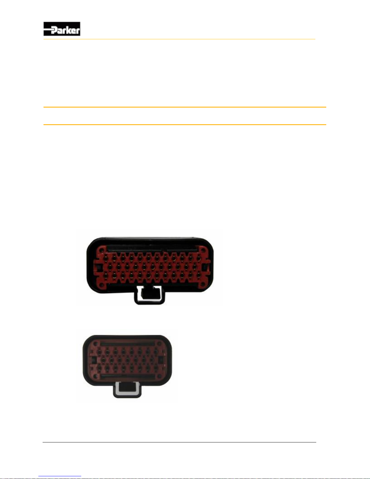
The following are pictures of the required mating connectors:
Figure 17: Black (J1) connector
Figure 18: Black (J2) connector
8. Connectors
Page 55
User Guide 45
Connectors
8.1. Mating Connector Part Numbers
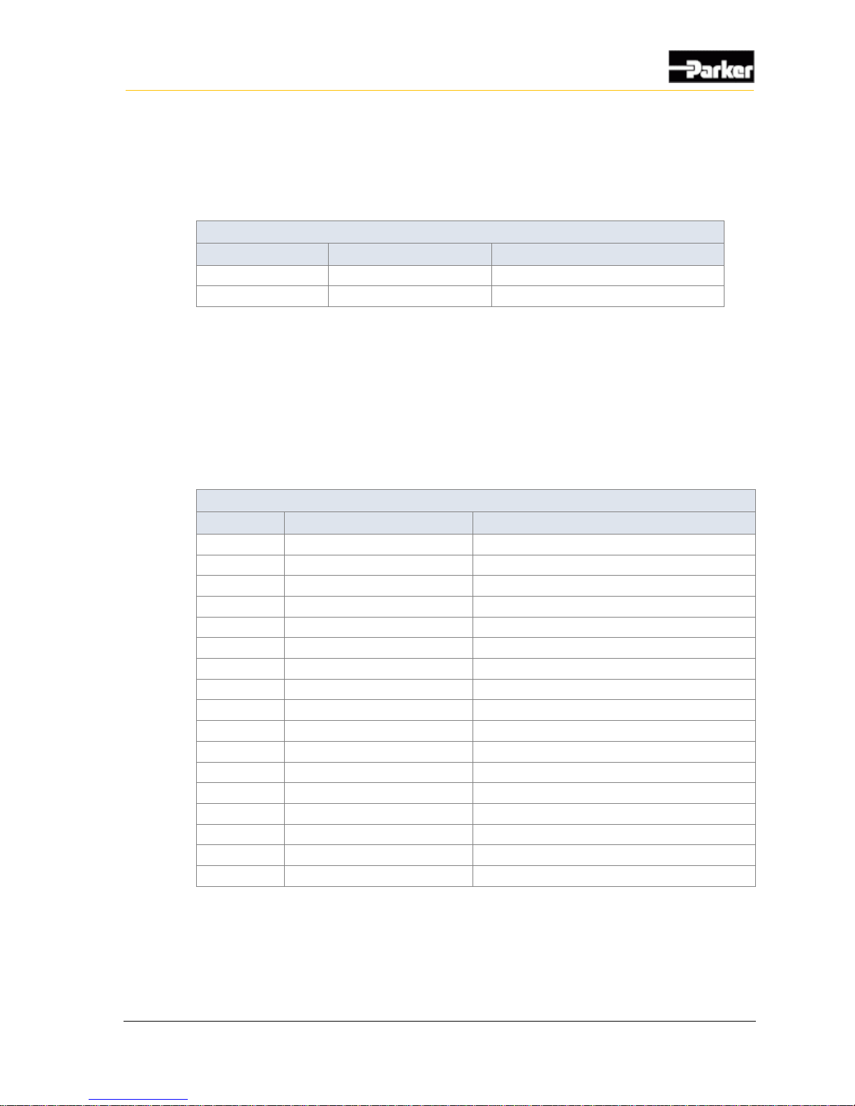
The following table shows the part numbers for the mating connectors and
terminals that are used in the vehicle harness:
Mating Connector Part Numbers
Connector
Shell part number
Terminal part number
Black (J1) 35-pin
AMP 776164-1
20-16AWG, Gold: AMP 770854-3
Black (J2) 23-pin
AMP 770680-1
20-16AWG, Gold: AMP 770854-3
8.2. Pinouts
Connector pins connect to inputs, outputs, power, and communication channels.
They provide the interface between the vehicle harness and the internal circuitry
of the VMM2404.
The following tables show the pinouts for the 35-pin and 23-pin connector,
respectively:
Black (J1) 35-Pin Connector Pinout
Pin
Name
Function
1
OUTPUT3_3A_HS
3A High-side output
2
OUTPUT7_3A_LS
3A Low-side output
3
SENSOR SUPPLY
Power for external sensors
4
ADDR4
Addressing digital input
5
ADDR3
Addressing digital input
6
ADDR2
Addressing digital input
7
ADDR1
Addressing digital input
8
VBATT
Logic and output power
9
VBATT
Logic and output power
10
VBATT
Logic and output power
11
OUTPUT5_3A_LS
3A Low-side output
12
OUTPUT1_3A_HS
3A High-side output
13
N-C
Not connected
14
ADDR5
Addressing digital input
15
CAN1_H
CAN 1 High
16
GND
Ground
17
INPUT6_ADF
Input: Analog, Digital, or Frequency
Page 56

46 VMM2404
Connectors
Black (J1) 35-Pin Connector Pinout
Pin
Name
Function
18
GND
Ground
19
N-C
Not connected
20
GND
Ground
21
N-C
Not connected
22
GND
Ground
23
N-C
Not connected
24
OUTPUT8_3A_HS
3A Low-side output
25
OUTPUT4_3A_HS
3A High-side output
26
CAN_SHLD
CAN Shield
27
CAN1_L
CAN 1 Low
28
POWER_CONTROL
Active high wake up input
29
INPUT5_ADF
Input: Analog, Digital, or Frequency
30
INPUT4_ADF
Input: Analog, Digital, or Frequency
31
INPUT3_ADF
Input: Analog, Digital, or Frequency
32
INPUT2_ADF
Input: Analog, Digital, or Frequency
33
INPUT1_ADF
Input: Analog, Digital, or Frequency
34
OUTPUT2_3A_HS
3A High-side output
35
OUTPUT6_3A_LS
3A Low-side output
Page 57

User Guide 47
Connectors
Black (J2) 23-Pin Connector Pinout
Pin
Name
Function
1
INPUT7_ADF
Input: Analog, Digital, or Frequency
2
INPUT8_ADF
Input: Analog, Digital, or Frequency
3
INPUT9_ADF
Input: Analog, Digital, or Frequency
4
INPUT10_ADF
Input: Analog, Digital, or Frequency
5
INPUT11_ADF
Input: Analog, Digital, or Frequency
6
INPUT12_ADF
Input: Analog, Digital, or Frequency
7
INPUT13_ADF
Input: Analog, Digital, or Frequency
8
INPUT14_ADF
Input: Analog, Digital, or Frequency
9
INPUT15_ADF
Input: Analog, Digital, or Frequency
10
INPUT16_D
Input: Digital
11
INPUT17_D
Input: Digital
12
INPUT18_D
Input: Digital
13
INPUT19_D
Input: Digital
14
INPUT20_D
Input: Digital
15
INPUT21_D
Input: Digital
16
INPUT22_D
Input: Digital
17
INPUT23_D
Input: Digital
18
INPUT24_D
Input: Digital
19
N-C
Not connected
20
N-C
Not connected
21
N-C
Not connected
22
N-C
Not connected
23
N-C
Not connected
Page 58
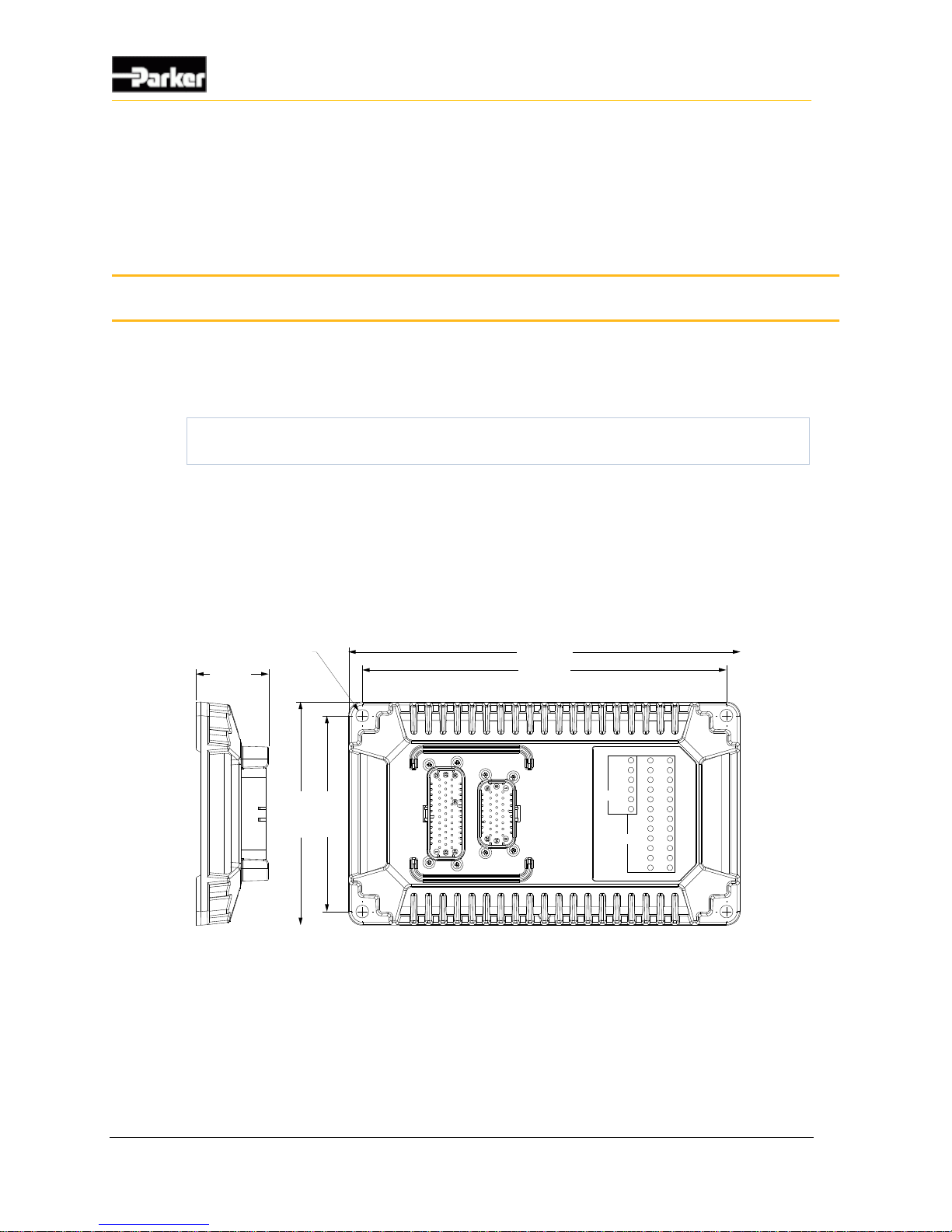
48 VMM2404
Installation
Because every system is different, it is not feasible to provide detailed installation
instructions that will be suitable for every assembly. This chapter therefore
provides only high-level guidelines on installing the VMM2404.
The vehicle manufacturer is responsible for creating procedures for mounting
the VMM2404 in a vehicle during production assembly.
9.1. Mechanical Installation Guidelines
Use the following guidelines when installing the VMM2404 in a vehicle.
9.1.1. Dimensions
The following shows the dimensions of the VMM2404:
254 [10.0 in]
236 [9.3 in]
47 [1.9 in]
1
4
5
[
5
.
7
i
n
]
1
2
7
[
5
.
0
i
n
]
Ø8.2 [.32 in]
PWR
NET
OUT
IN
1
2
1
2
3
4
12 24
13
VMM2404
Figure 19: Dimensions of the VMM2404
9.1.2. Selecting a Mounting Location
The VMM2404 can be installed in the vehicle's cab or on the chassis. If used in a
marine application, ensure that it is protected from excessive salt spray.
9. Installation
Page 59

User Guide 49
Installation
Before mounting the VMM2404, review the following environmental and
mechanical requirements.
Note: Do not install the VMM2404 near any significant heat sources, such as
a turbo, exhaust manifold, etc. Avoid installing the VMM2404 near any drivetrain component, such as a transmission or engine block.
9.1.2.1. Environmental Requirements
The VMM2404 warranty does not cover damage caused by exposure of the
product to environmental conditions that exceed its design limitations.
1. Mount the VMM2404 in an environment that is within its ambient
temperature range of –40 °C to +85 °C.
2. Mount the VMM2404 in an environment that is within its particle ingress
rating. The sealing standard for the VMM2404 is EP455 level 1.
Note: The VMM2404 has not been tested for water ingress according to the
EP455 level 1 standard.
The VMM2404 is protected from aggressive pressure wash up to 1000 psi at 1 m
(3.28 ft.).
Warning! Damage to equipment. Exercise caution when pressure-
washing the VMM2404. The severity of a pressure wash can exceed the
VMM2404 pressure wash specifications related to water pressure, water
flow, nozzle characteristics, and distance. Under certain conditions a
pressure wash jet can cut wires.
9.1.2.2. Mechanical Requirements
Review the following mechanical requirements before selecting a mounting
location for the VMM2404:
The VMM2404 should be mounted vertically so moisture will drain away
from it.
The wire harness should have drip loops incorporated into the design to divert
water away from the VMM2404.
The harness should be shielded from harsh impact.
The harness should connect easily to the connector and have adequate bend
radius.
The labels and LEDs should be easy to read.
The VMM2404 should be in a location that is easily accessible for service.
Page 60

50 VMM2404
Installation
9.1.3. Mounting the VMM2404 to a Vehicle
It is up to the original equipment manufacturer (OEM) to ensure the product is
securely mounted to the vehicle.
The following guidelines are related to physically attaching the VMM2404 to a
vehicle:
Secure the VMM2404 with bolts in all bolt holes using Hex Head 1/4"-20 or
equivalent metric size (6 mm) bolts.
The bolts should be tightened according to the fastener manufacturer's
tightening torque specifications.
9.2. Electrical Installation Guidelines
Use the following guidelines when installing the VMM2404 in a vehicle.
9.2.1. Designing and Connecting the Vehicle Harness
The vehicle manufacturer is responsible for designing a vehicle harness that mates
with the VMM2404 connector(s).
The vehicle harness design depends on the following:
How the VMM2404's inputs, outputs, communication, and power pins are
configured.
Other components on the vehicle and their physical locations.
The routing of the harness.
Suggested wire sizing for the various connections are as follows:
Inputs, 18 AWG
Outputs, 16 AWG
Logic power and ground, 18 AWG
Other powers and grounds, 16 AWG
Busbar power, if applicable, 14 AWG per 20 A of current (or 8 AWG per 40
A of current for single pin busbar connectors)
Once the vehicle harness is designed, it can be connected to the VMM2404
simply by clicking the mating connector into the connector port on the
VMM2404.
Page 61

User Guide 51
Application Examples
The purpose of this section is to provide examples of how the VMM2404 can be
used for different purposes.
The following examples (used for illustrative purposes only) are covered in this
section:
Implementing safety interlocks
Controlling indicator lights
Controlling a proportional valve
Controlling motor speed
Using one analog input as two digital inputs
Connecting sensors
10.1. Implementing Safety Interlocks
Safety is paramount when creating controls for a vehicle.
One safety feature that can be implemented with the VMM2404 is to ensure the
vehicle doesn't move when it is not being used, and no one is sitting in the
operator's seat.
To prevent the vehicle from moving when no one is sitting in the operator seat:
1. Place a seat switch interlock on the operator seat and connect the switch to a
digital input.
2. Write application code for the digital input so that it shuts down critical
vehicle functions when the switch is open (when no one is sitting in the seat).
Note: The example above may cause unwanted shutdowns if the operator
moves around while controlling the vehicle. To prevent this, use software
filtering that will prevent the vehicle from shutting down unless the switch is
open for more than a defined period of time.
10. Application Examples
Page 62
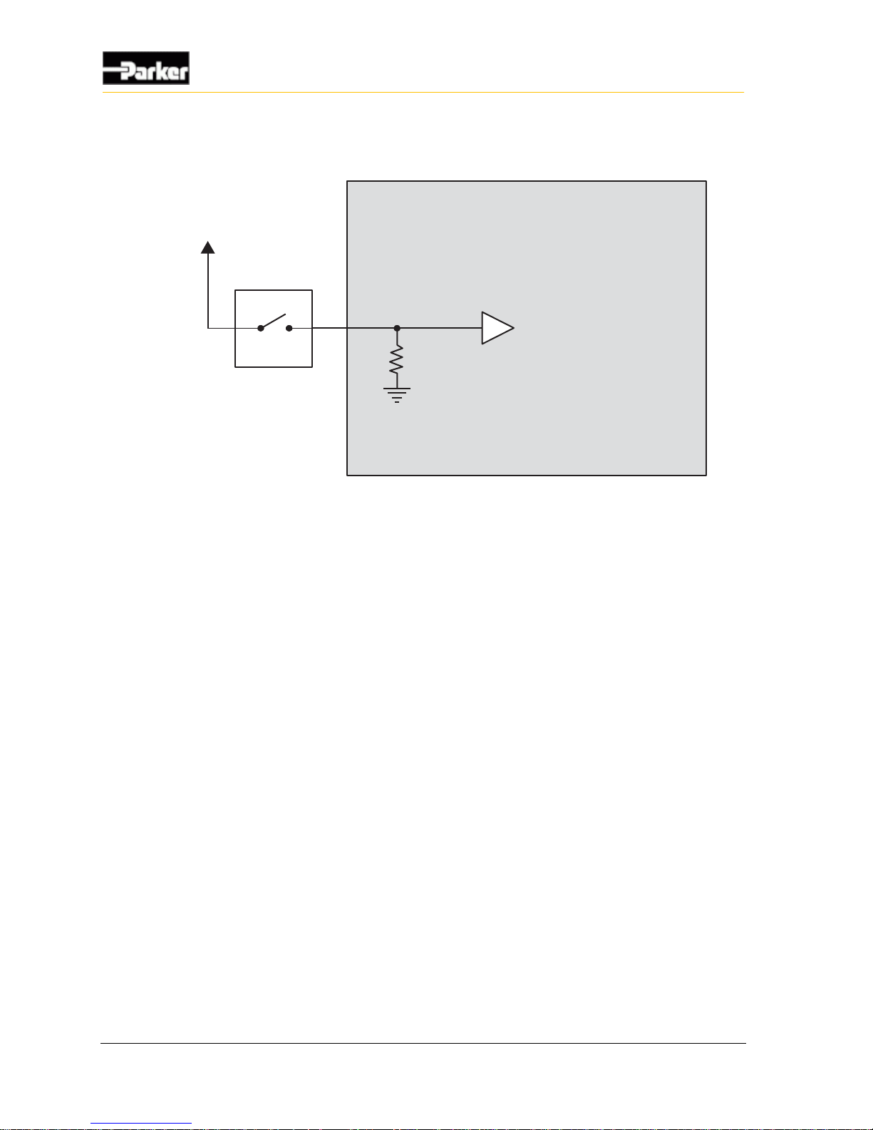
52 VMM2404
Application Examples
The following diagram shows a typical seat switch interlock connection:
Internal to product
Battery Voltage
Driver Present Switch
Digital Input
Figure 20: Seat switch interlock connection
10.2. Controlling Indicator Lights
Multiple VMM2404 can be used together in a system to control a vehicle's
indicator lights. For example, you could connect three VMM2404s,
communicating over the CAN bus, as follows.:
Connect one VMM2404 to the rear indicator lights.
Connect one VMM2404 to the front indicator lights.
Connect one VMM2404 to the turn signal and hazard switches.
Page 63

User Guide 53
Application Examples
The following shows how to connect three VMM2404s together in a system to
control indicator lights:
Rear Left Signal Light
RightTurnSignal Switch
LeftTurnSignal Switch
Hazard Signal Switch
Front Right Signal Light
Front Left Signal Light
Rear Right Signal Light
Rear
Cabin
Front
VBAT VBAT
VBAT
CAN
3.3k 3.3k
3.3k
Figure 21: Indicator light connections
10.3. Controlling a Proportional Valve
The VMM2404 can be used to control a proportional hydraulic valve through a
high-side output with PWM capability, and a low-side output with current sense.
Note: The VMM2404 has Proportional-Integral-Differential (PID) capabilities
that make it possible to control devices like proportional valves through
Page 64
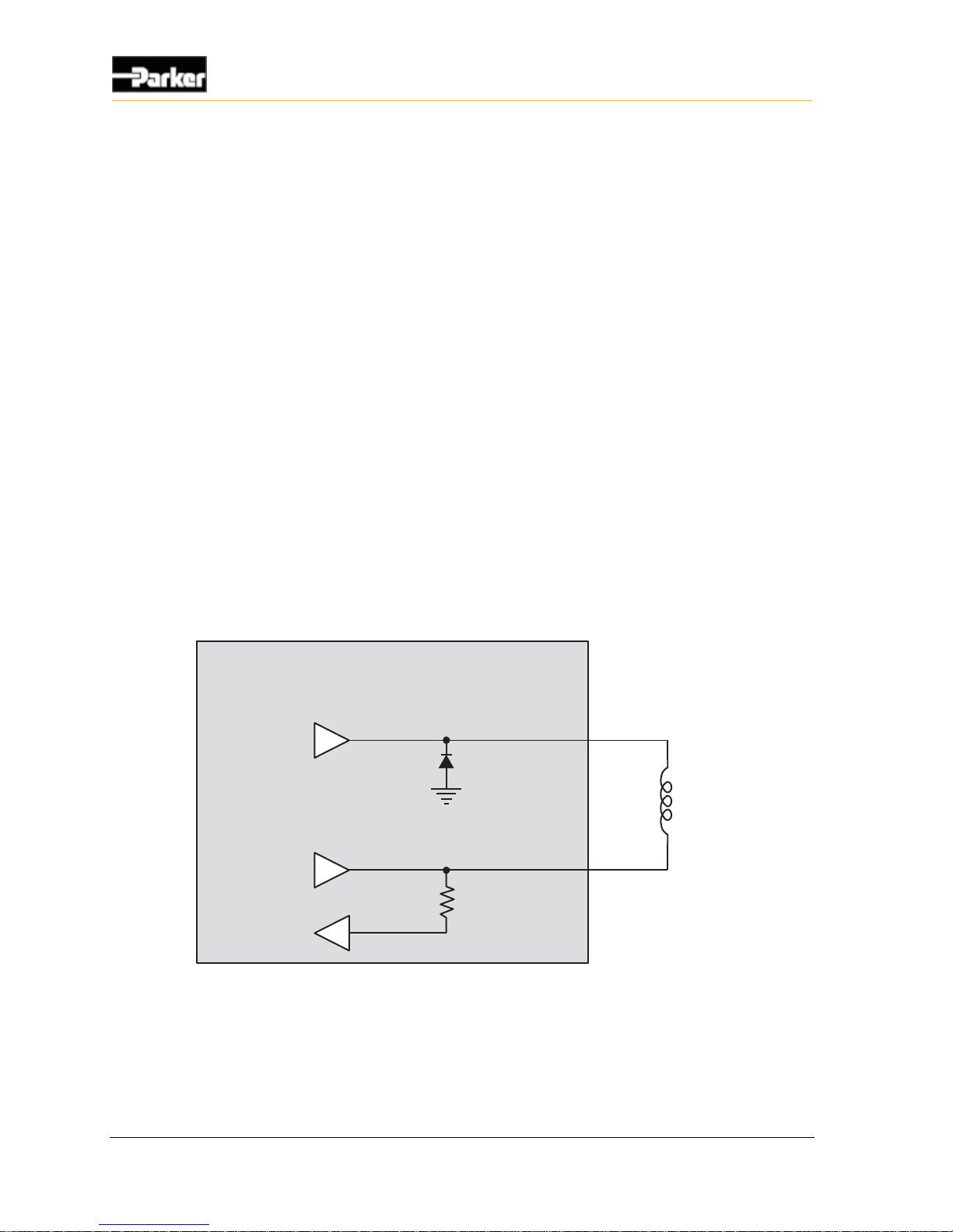
54 VMM2404
Application Examples
software. Refer to the appropriate software manual, or contact your Parker
Vansco Account Representative for more details about software. This section
only provides hardware connection information.
When making the connection, it is highly recommended to use the high-side and
low-side outputs in pairs to avoid potential problems.
The high-side output would drive power to the valve coil and adjust the duty
cycle of a PWM signal.
The low-side output would be used as a return path to ground for the valve
coil, and provides feedback on the amount of current flowing through the
valve coil.
The application code should be written so that the PWM duty cycle for the output
is adjusted to achieve a target current through the valve coil.
If current feedback is lower than target, the PWM duty cycle should increase
to boost average current through the valve coil.
If the current feedback is higher than target, the PWM duty cycle should
decrease to reduce average current through the valve coil.
The following shows how to connect a high-side and low-side output to control a
proportional hydraulic valve:
Internal to product
Valve
Coil
Low-Side Output
with current sense
High-Side Output
(PWM)
Figure 22: Connection for controlling a proportional valve
Page 65
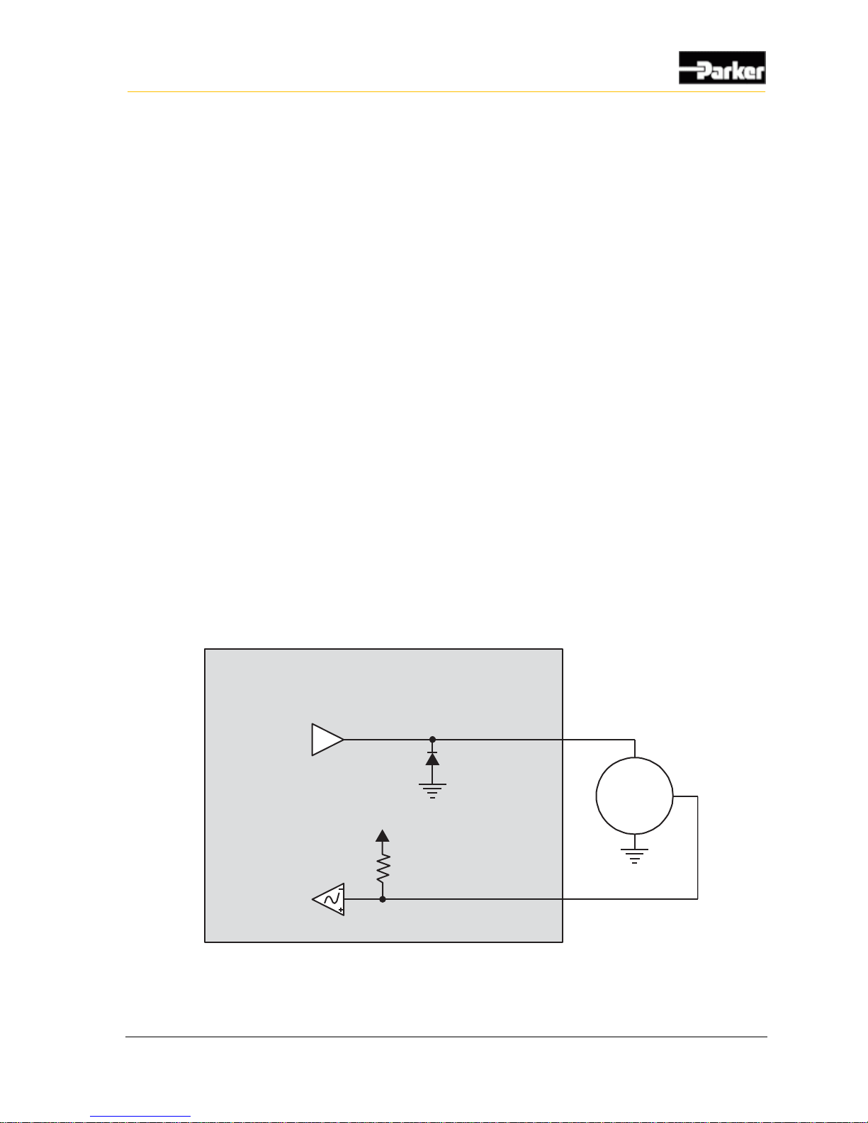
User Guide 55
Application Examples
10.4. Controlling Motor Speed
The VMM2404 can be used to control the DC motor speed of motors that provide
a tachometer output.
Note: The VMM2404 has Proportional Integral Differential (PID) capabilities
that make it possible to control devices like proportional valves through
software. Refer to the appropriate software manual, or contact your Parker
Vansco Account Representative for more details about software. This section
only provides hardware connection information.
To do this, you would use a high-side output with PWM capabilities to control the
speed of the motor, and a DC-coupled frequency input to monitor the output from
the motor.
The application code should be written so that the PWM duty cycle for the highside output is adjusted to achieve a target speed (frequency) for the motor.
If the frequency feedback is lower than target, the PWM duty cycle should
increase to boost the average current through the motor to speed it up.
If the frequency feedback is higher than target, the PWM duty cycle should
decrease to reduce average current through the motor to slow it down.
The following shows how to connect the VMM2404 to control the speed of a
motor:
Internal to product
Motor
Frequency Input
High-Side Output
(PWM)
Battery Voltage
Figure 23: Connection for controlling motor speed
Page 66
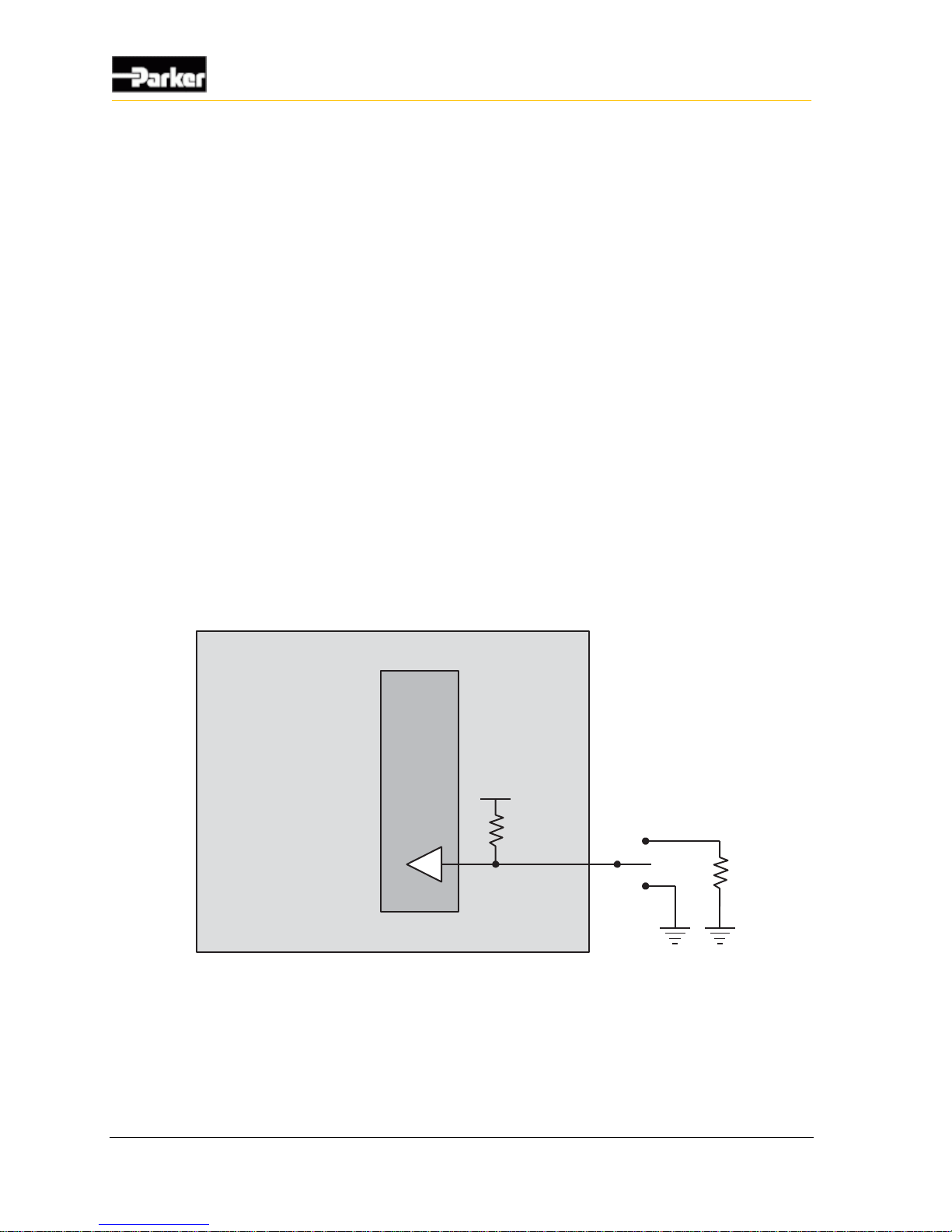
56 VMM2404
Application Examples
10.5. Using one Analog Input as Two Digital Inputs
The VMM2404 allows you to use one analog input as two digital inputs, which is
useful in reducing harness lead or if you are running out of digital inputs in your
system.
To do this, you would connect the analog input to a single pole, double throw
(SPDT) switch.
Note: You will need to write your application logic to act according to the
voltage value readings provided by the analog input. Refer to the appropriate
help file, or contact your Parker Vansco Account Representative for more
information.
When making the connection, ensure there is a voltage difference between the
two pins on the SPDT switch. This can be done by
enabling the internal pull-up resistor on the analog input (done through
software)
adding a resistor to one of the pins on the SPDT switch.
The following shows how to connect an analog input to a SPDT switch:
Internal to product
Analog Input
VBAT
3.3 kohm
3.3 kohm
Figure 24: Connecting an analog input to an SPDT switch
Page 67
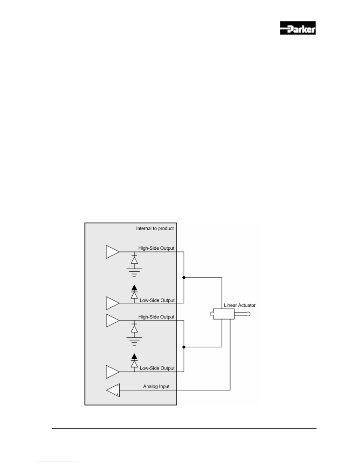
User Guide 57
Application Examples
10.6. Controlling a Linear Actuator
The VMM2404 can control the position of a linear actuator by using two hbridges of high-side and low-side outputs, and monitor the position of the actuator
using an analog input. When making the connections, it is highly recommended to
use the high-side and low-side outputs in pairs to avoid potential problems (use
high-side output 1 with low-side output 1, etc.).
Note: The VMM2404 has Proportional-Integral-Differential (PID) capabilities
that make it possible to control devices like proportional valves through
software. Refer to the appropriate software manual, or contact your Parker
Vansco Account Representative for more details about software. This section
only provides hardware connection information.
The software should be written to adjust the PWM duty cycle and direction of the
current to achieve a target position for the linear actuator.
The following shows how to connect high-side and low-side outputs for
controlling a linear actuator:
Figure 25: Connection for controlling a proportional valve
Page 68

58 VMM2404
Application Examples
10.7. Connecting Various Sensors
There are many types of sensors that can be connected to the VMM2404, as
follows:
Open collector sensors
Variable resistance sensors
Variable reluctance sensors
Switch sensors
Voltage sensors
CMOS sensors
Potentiometer (ratiometric) sensors
Note 1: To optimize the reading accuracy for sensors, dedicate one of the
main ground pins (called GND) as a low-current ground return for all sensors
on the vehicle.
Note 2: When connecting sensors to the VMM2404, use the sensor's
specification to ensure that the VMM2404 is configured correctly for the
sensor.
10.7.1. Open Collector
Open collector sensors are compatible with each type of input on the VMM2404.
Open collector sensors are typically used in applications that require digital or
frequency measurements. They work by pulling voltage down to ground or up to
power when activated, and are basically a switch that turns on and off.
Note: Open collector sensors need a pull-up or pull-down resistor to bias the
state of the sensor when the sensor is not activated. Pull-up and pull-down
resistors are internal to the VMM2404.
Page 69
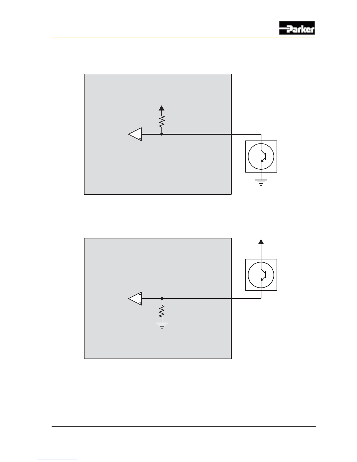
User Guide 59
Application Examples
The following shows a typical NPN open collector sensor connection:
Internal to product
Digital or frequency Input
Open
collector
Figure 26: Open collector sensor connection
The following shows a typical PNP open collector (also called open emitter)
sensor connection:
Internal to product
Digital or frequency Input
Open
collector
Figure 27: Open collector active high connection
Page 70
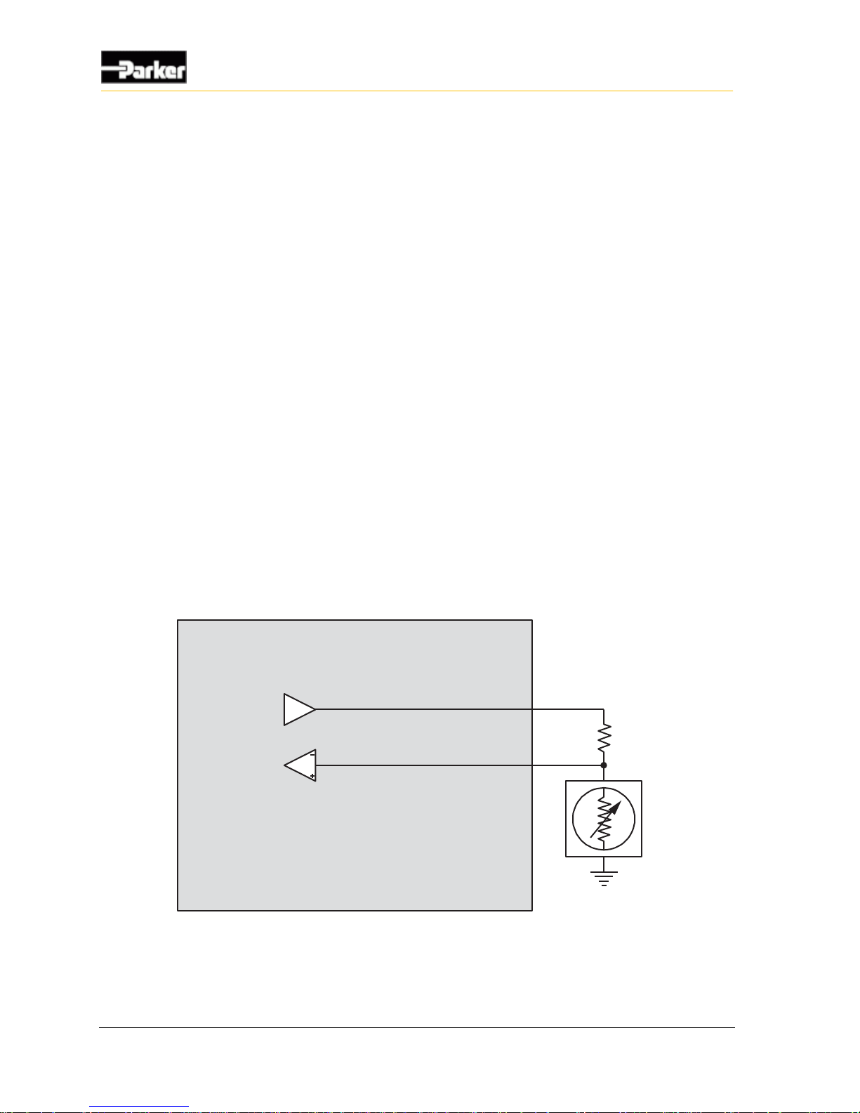
60 VMM2404
Application Examples
10.7.2. Variable Resistance
Variable resistance sensors change impedance to represent it's measured value,
and are compatible with analog inputs.
Variable resistance sensors are typically used in thermal and pressure
applications. They work by changing the voltage reading on the sensor according
to changes in pressure or temperature in the application.
The VMM2404 cannot measure resistance directly.
To make the VMM2404 measure resistance accurately, do the following:
Include a precision pull-up resistor between the sensor and the sensor power
output (called SENSOR_SUPPLY).
Ensure the value of the precision resistor allows the maximum possible
resolution for the sensor's input.
Dimension the precision resistor to get the maximum voltage range from the
sensor.
Note: Variable resistance sensor accuracy may suffer at the extremes of the
sensor's range. A tolerance analysis should be performed to ensure
measurement accuracy is acceptable for your application.
The following shows a typical variable resistance sensor connection:
Internal to product
Analog Input
Sensor Power
Variable
Resistance
Sensor
Precision
Resistor
Figure 28: Variable resistance sensor connection
Page 71
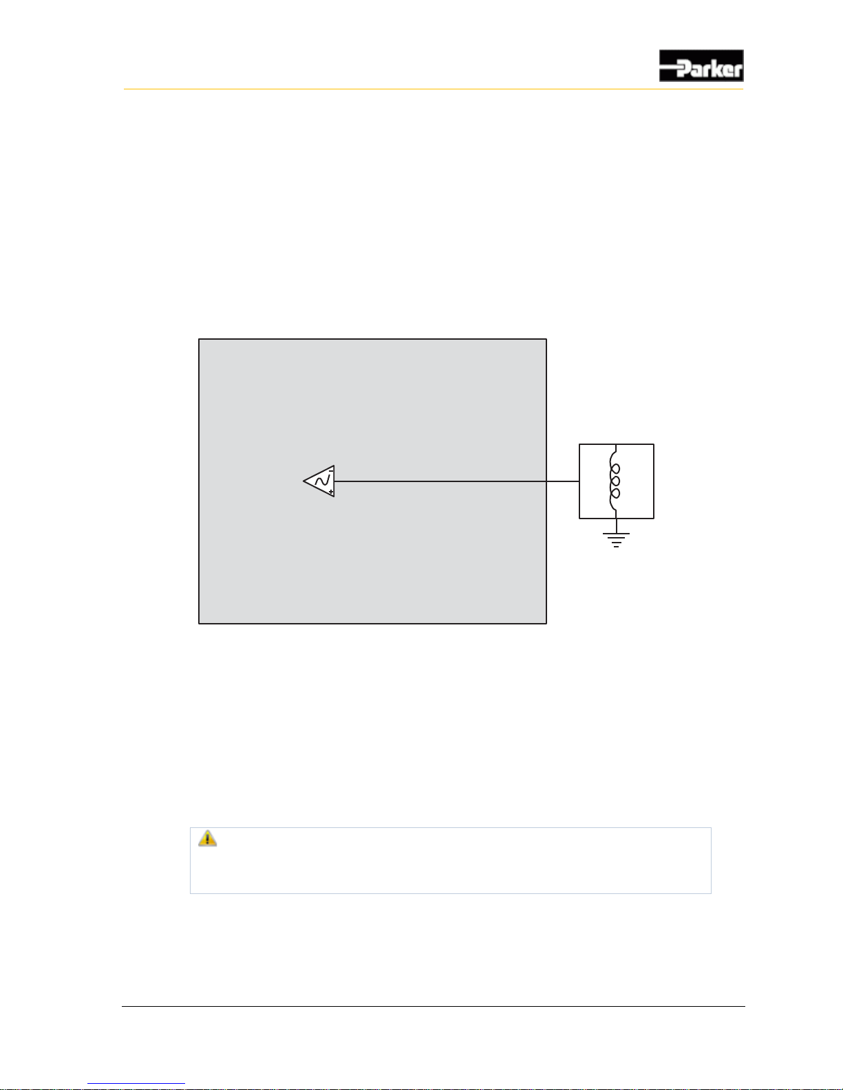
User Guide 61
Application Examples
10.7.3. Variable Reluctance
Variable reluctance sensors are typically used in frequency measurement
applications, and are compatible with AC-coupled frequency inputs.
Variable reluctance sensors do not require power (the power is induced), and they
create frequency by out-putting a sine wave type signal. They work by using an
increase or decrease in a magnetic field to detect the proximity of a part or device.
The following shows a typical variable reluctance connection:
Internal to product
AC Coupled Frequency Input
Variable
Reluctance
Sensor
Figure 29: Variable reluctance sensor connection
10.7.4. Switch
A switch is a type of sensor that uses mechanical contacts in one of two states:
open or closed. Sensor switches are used to turn sensors on and off, and can be
wired directly to digital inputs.
Active-low sensor switches are common. To use active-low switches, the internal
pull-up resistor on the input that the sensor is wired to must be enabled.
Use of active-low switches is not recommended. A broken wire on this
type of switch, if it makes contact with the chassis, will activate the
function.
Active-high sensor switches are another common type which are generally safer.
To use active-high switches, the internal pull-down resistor for the input that the
sensor is wired to must be enabled.
Page 72

62 VMM2404
Application Examples
The following shows a typical sensor switch connection:
Internal to product
Switch
Digital Input
Battery voltage
Figure 30: Switch sensor connection
10.7.5. Voltage
Voltage type sensors work by driving an analog voltage signal to report the
sensor's measured value.
Voltage sensors are compatible with analog inputs, and are typically used in
applications that require variable voltage measurements.
Note: Ensure you configure the analog input voltage (gain and attenuation
factors) so the input's voltage is close to, but higher than, the maximum output
voltage of the sensor.
Page 73

User Guide 63
Application Examples
The following shows a typical voltage sensor connection:
Internal to product
Analog Input
Voltage
Sensor
Figure 31: Voltage sensor connection
10.7.6. CMOS
A sensor with a CMOS-type output drives a high and low signal, and is typically
used in digital and frequency applications, and therefore, CMOS sensors can be
wired directly to digital and frequency inputs.
The following shows a typical CMOS sensor connection:
Internal to product
Digital or Frequency Input
CMOS
Figure 32: CMOS sensor connection
Page 74
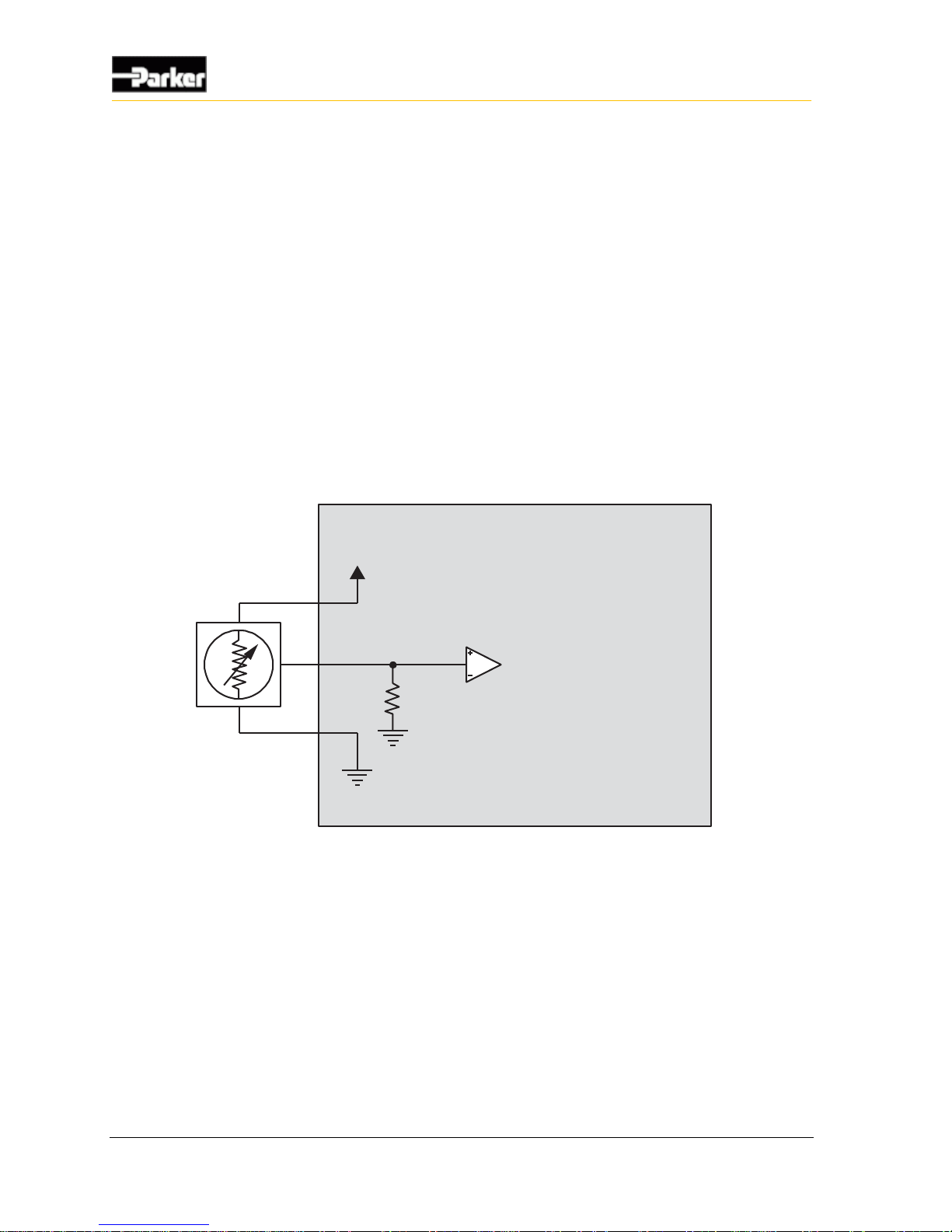
64 VMM2404
Application Examples
10.7.7. Potentiometer (Ratiometric)
Potentiometers and other ratiometric type sensors can be wired directly to analog
inputs.
Potentiometers are resistive devices that use a wiper arm to create a voltage
divider. Changes to resistive measurements happen as the wiper arm moves along
a resistive element.
When connecting potentiometer sensors, it is important to do the following:
Connect one end of the sensor to the SENSOR_SUPPLY pin, and the other end to
a GND pin on the VMM2404.
Connect the sensor signal to an analog input.
The following shows a typical potentiometer sensor connection:
Internal to product
Sensor Voltage
Sensor Ground
Potentiometer
Analog Input
Figure 33: Potentiometer (ratiometric) sensor connection
Page 75
User Guide 65
Tests
The following table lists the results for verification tests that were performed for
the VMM2404:
Ref #
Test Specification
Test Description
Notes
1.
J1455 (Jun2006) Section
4.1.3.1
24 Hour Thermal Cycle
2.
J1455 (Jun2006) Section
4.1.3.2
Thermal Shock
3.
EP455 (Feb 03) Section 5.1.2
Storage Temperature
4.
J1455 (Jun2006) Section
4.2.3
24 Hour Humidity Cycle
5.
EP455 (Feb 03) Section
5.13.2
Humidity Soak
6.
J1455 (Jun2006) Section
4.3.3
Salt Spray Atmosphere
7.
EP455 (Feb 03) Section 5.8.2
Chemicals, Brush Exposure
8.
EP455 (Feb 03) Section 5.4.1
Solar Radiation - UV Effects
9.
EP455 (Feb 03) Section 5.6
Pressure Wash
10.
J1455 (Jun2006) Section
4.9.4.2
Mechanical Vibration, Random
11.
J1455 (Jun2006) Section
4.11.3.1
Handling Drop
12.
J1455 (Jun2006) Section
4.11.3.1
Harness Shock
13.
J1455 (Jun2006) Section
4.11.3.1
Operational Shock
14.
J1455 (Jun2006) Section
4.13.1
Operating Voltage
15.
EP455 (Feb 03)
Section 5.10.7
Operational Power Up
16.
J1455 (Jun2006) Section
4.13.1
Cold Cranking Voltage
11. Tests
Page 76

66 VMM2404
Tests
Ref #
Test Specification
Test Description
Notes
17.
J1455 (Jun2006) Section
4.13.1
Jumper Starts Voltage
18.
J1455 (Jun2006) Section
4.11.1.1.1
Steady State Reverse Polarity
19.
EP455 (Feb 03)
Section 5.10.4
Short Circuit Protection
20.
EP455 (Feb 03)
Section 5.11.1
Transient Accessory Noise
21.
EP455 (Feb 03)
Section 5.11.2
Transient Alternator Field Decay
22.
EP455 (Feb 03)
Section 5.11.3
Transient Batteryless Operation
Level
23.
J1455 (Jun2006) Section
4.13.2
Transient Inductive Load
Switching Pulse 1
24.
J1455 (Jun2006) Section
4.13.2
Transient Load Dump
25.
J1455 (Jun2006) Section
4.13.2
Transient Mutual Coupling Power
Lines
26.
J1455 (Jun2006) Section
4.13.2
Transient Mutual Coupling Signal
Lines
27.
J1455 (Jun2006) Section
4.13.2.2.3
Electrostatic Discharge Operating
28.
J1455 (Jun2006) Section
4.13.2.2.3
Electrostatic Discharge Handling
29.
J1455 (Jun2006) Section
4.13.3
EMC - Susceptibility
30.
J1455 (Jun2006) Section
4.13.3
EMC - Emissions
Page 77

User Guide 67
Frequently Asked Questions (FAQ)
What are the recommended mounting practices for the VMM?
Refer to Selecting a Mounting Location for details.
Can the VMM be pressure washed or immersed in water?
Refer to Environmental Requirements on page 49 for details.
Can the VMM be used as an H-bridge?
Yes. The VMM has separate high-side and low-side outputs that can be combined
in the harness to create an H-bridge. Refer to Application Examples on page 51
for more details on how to create an H-bridge.
Will the VMM work on a 42 V electrical system?
No. The VMM is designed for 12 V and 24 V systems.
Should the VMM be disconnected when the welding on a vehicle where it is
installed?
All electrical devices should be disconnected during welding to avoid damaging
them. The VMM warranty does not cover damage to the product when exposed to
conditions that exceed the design limitations of the product.
How does the power control feature work?
Refer to Power on page 35 for details.
How should I wire my CAN network?
Refer to Communication on page 39 for details.
Where can I get J1939 cables and connectors?
Two manufacturers of J1939-rated connectors are ITT Canon and Deutsch.
Raychem, a subdivision of Tyco, manufactures a shielded cable compliant with
J1939-11. These are manufacturers that Parker Vansco has experience with, but
this should not be considered an exhaustive list of J1939 cable and connector
suppliers. Consult your local wire and connector distributors for details.
12. Frequently Asked Questions (FAQ)
Page 78
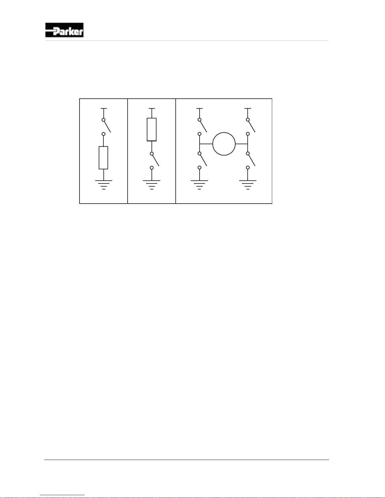
68 VMM2404
Frequently Asked Questions (FAQ)
What kind of circuits can be created with the outputs?
Outputs can be used to create high-side, low-side, and H-bridge circuits, as shown
in the following:
VBATVBAT VBAT VBAT
High Side Circuit Low Side Circuit H-Bridge Circuit (2xBidirectional)
M
How do I program the VMM?
The VMM can be programmed using ladder logic. Consult your Parker Vansco
Account Representative for more details.
Do the output currents require de-rating in certain conditions?
VMM outputs do not require de-rating. They are specified to operate continuously
at the maximum temperature and the maximum rated current.
Can I plug my existing sensor into a VMM, and if so, how do I configure the input?
Refer to Sensor Power see "Sensor supply" on page 37, or Connecting Various
Sensors on page 58 for details on connecting sensors. Contact your Parker Vansco
Account Representative for more information if needed.
Is it possible to purchase the VMM with a company logo printed on it?
Parker Vansco may consider customizing the overlay on a case-by case-basis.
Consult your Parker Vansco Account Representative for details.
Is it possible to purchase a pre-programmed VMM?
Yes. Contact your Parker Vansco Account Representative for details on getting
your VMM pre-programmed.
What torque should I apply to the mounting bolts?
Refer to the fastener manufacturer's recommendations for mounting bolt
tightening torque.
Page 79

User Guide 69
Frequently Asked Questions (FAQ)
Is it possible to get the VMMs with different connector options?
No. VMM connector options are not offered because the connectors are integral
to the circuit board and mechanical enclosure design.
What is the maximum bus loading on the CAN network?
Requirements can vary by system; however, the industry standard is no more than
50% average bus loading.
Do I need to fuse VMM power?
Yes. Power connections to the VMM should be fused. Refer to Power on page 35
for more details.
Do I need to fuse VMM outputs?
VMM outputs are internally protected and no external fusing is required.
How much wetting current is provided by the VMM inputs?
Wetting currents can vary by module and by input type. Wetting current
specifications are found in the specifications tables for each input.
Do I need an external flyback diode on my inductive load?
No. The VMM has internal flyback diodes as part of its high-side driver circuitry,
and therefore an external flyback diode is not needed.
Is it a problem to have an external flyback diode on my inductive load? Will it affect
my current sense measurement?
No. Having an external flyback diode present on circuits with internal flyback
diodes will not cause problems and will not affect the current sense measurement.
Does the VMM offer analog outputs?
No; however, with the addition of external circuitry, an output can be PWM'd to
generate an analog voltage.
Can I vary the frequency of my PWM output?
The frequency of each output is determined through software. Consult the
appropriate software manual for details.
Can I connect VMM outputs in parallel?
You can connect on/off controlled outputs in parallel, but PWM’d outputs cannot
as they are not guaranteed to be synchronized.
My VMM is broken. Who do I call regarding warranty?
Broken VMMs should be returned to the service department of the OEM, and the
OEM will co-ordinate returns to the appropriate Parker Vansco service center.
Page 80

70 VMM2404
Frequently Asked Questions (FAQ)
Does the VMM support wireless connections?
The VMM does not support wireless connections; however, Parker Vansco offers
a CAN to WiFi module. Contact your Parker Vansco Account Representative for
details.
Can I connect the VMM to my existing J1939 devices?
Yes. The VMM is fully J1939 compatible and has generic J1939 messaging
capability to support any custom communication scheme.
Can I use the VMM to power another VMM?
Yes, an output on your VMM can be used to power other VMMs, or to excite
other VMMs' power control inputs.
Does the VMM2404 support "Wake on CAN"?
No.
Can I run my VMM CAN bus faster than 250 kbps?
No. When the VMM is used in a VMM system, it can only communicate at
250kbps.
Can I use other Parker Vansco products such as the CM3620 with my VMMs?
Yes, however, the software required for each is different. Interfacing to these type
modules must be done through the generic CAN and J1939 messaging included in
the VMMS software tool.
Page 81

User Guide 71
Troubleshooting
This section assumes that the product is connected in a Development System.
The following table provides possible solutions for potential problems:
Problem
Possible Causes
Possible Solutions
Everything is
connected, but
there is no CAN
communication.
The VMM is not powered.
Ensure all of your connecting points in
the desktop setup are properly seated.
Ensure the power supply is on and
connected to a VMM2404 within your
desktop setup.
Ensure the power control input is active
(refer to the power control input section
for details).
The power LED will flash once every second
when the VMM2404 is powered.
The CAN bus is not set up
correctly.
Ensure there is a 120 terminating
resistor at each end of the CAN bus.
13. Troubleshooting
Page 82

User Guide 72
AC-coupled
A circuit that eliminates the DC offset voltage of the signal. This circuit is
typically used with frequency inputs that have a DC offset. Note that the DC
offset value varies by product.
active high
Input type that is on when it reads a battery voltage level, and off when it is
floating or grounded.
active low
Input type that is on when it reads a ground voltage level, and off when it is
floating or connected to battery voltage.
aliasing
In analog-to-digital conversion, distortion that occurs when the analog signal
being sampled has a frequency greater than half the sample rate. An example of
aliasing is the wagon-wheel effect often seen in films, in which a spoked wheel
appears to rotate differently from its true rotation.
amplified
A circuit that applies a gain with a value greater than one (1) to a measured signal,
which is typically used with analog inputs.
analog input
An input that allows a voltage level to be read and converted to discrete digital
values within a microprocessor.
anti-alias filtering
Filters incorporated in hardware that ensure the analog value being read by the
module does not have a frequency component greater than half the sample rate.
application software
A level of software that makes a product (hardware) perform desired functions for
the end user.
14. Glossary
Page 83

User Guide 73
Glossary
attenuation
A gradual decrease in a current's intensity. Such a decrease may occur naturally,
or intentionally through the use of an attenuator.
black box
A custom-compiled algorithm written in C programming language that allows a
system designer to implement algorithms that are not possible in ladder logic.
CAN bus
See controller area network (CAN) bus.
CAN high
The positive wire in a shielded twisted-pair cable, which, when connected with a
CAN low, provides a complete CAN differential signal.
CAN low
The negative wire in a shielded twisted-pair cable, which, when connected with a
CAN high, provides a complete CAN differential signal.
CAN shield
The shielding that wraps around the CAN high and CAN low wires in a shielded
twisted-pair cable.
CMOS
See Complementary Metal-Oxide Semi-Conductor.
controller area network (CAN) bus
A communications network bus that permits data from sensors and other
equipment within a motor vehicle to communicate with each other and, through
telltales and other diagnostic tools, with the operator.
controller I/O board
A development product that allows users to test products on a bench in a
development environment before installing the product on a vehicle.
controller module
Any module that has embedded software used for controlling input and output
functions.
current feedback
A circuit that allows software to measure the amount of current provided by the
outputs. This circuit is typically connected to an analog input that is connected to
the microprocessor. Also known as current sense or current sensing.
Page 84

74 VMM2404
Glossary
current feedback control
Varying the duty cycle of an output so that the output provides a desired amount
of current to the load.
current sensor
A device that detects electrical current in a wire and generates a signal
proportional to it.
data link adaptor (DLA)
A development tool that connects the CAN bus to a personal computer (through a
USB or RS232 port), so that programming and diagnostics can be performed on
the product before installing it in a vehicle.
DC-coupled
DC coupling passes the full spectrum of frequencies including direct current. The
signal being read by this circuit must fall within the detection threshold range
specified for the input.
de-rating
The reduction of the rated output current level to a value less than the specified
rating. De-rating is typically done so that a product does not overheat.
digital input
An input that is typically controlled by an external switch that makes the input
either active (on), or inactive (off).
dimension
To select values so that they generate optimal results.
driver (hardware)
An electronic device that switches power or ground to an external load. The driver
is a key component used in all output circuits.
driver (software)
A block of software that provides access to different hardware components.
field-effect transistor (FET)
A transistor whose flow of charge carriers is controlled by an external electric
field.
floating input
An input, isolated from a ground connection, that does not resist being pulled high
or low when inactive.
Page 85

User Guide 75
Glossary
frequency input
An input that allows a frequency value to be read from an oscillating input signal.
gain
To increase the voltage level of an input signal to maximize the resolution of an
input.
general purpose input
An input that can be used as an analog, digital, or frequency input.
ground level shift
An undesirable condition in which the ground level elevates. This condition can
cause inputs to activate when they shouldn't.
half-bridge
The simultaneous use of a high-side switch and a low-side switch in order to
provide a load having both a battery voltage and a ground.
harness address pins
The pins a product uses to identify itself within a system.
H-bridge
A combination of two half-bridge circuits used together to form one circuit. Hbridges provide current flow in both directions on a load, allowing the direction of
a load to be reversed.
high-side output
An output that provides switched battery voltage to an external load.
inductive load
A load that produces a magnetic field when energized. Inductors are electrical
components that store energy and are characterized by the following equation:
E
stored
LI
2
2
1
ladder logic
A programming language often used in industrial-control settings to control
electromechanical devices in a relay. Programs written in this language resemble
ladders: two vertical rails with a series of horizontal rungs—each representing a
logical rule—between them. Ladder programs for Parker Vansco products are
written using Vansco Multiplexing Module Software (VMMS).
Page 86

76 VMM2404
Glossary
load
Any component that draws current from a module and is typically switched on
and off with outputs. Examples include bulbs, solenoids, motors, etc.
logic power
Power pins for the microprocessor and logic peripherals.
low-side output
An output that provides a switched ground voltage to an external load.
multiplexing
Transmitting multiple messages simultaneously over one channel in a local area
network.
open load
The disconnection of a load from an output, often because of a broken or worn
wire or connector pin.
overcurrent
A fault state that occurs when a load draws more current than specified for an
output, which results in the output shutting down to protect the circuitry of the
product.
overvoltage
A situation in which the voltage in a circuit rises above its upper design limit.
power control input
A digital input that is used to turn on the product. When the input is active, the
product turns on and operates in normal mode; when the input is inactive, the
product powers down and will not operate.
procurement drawing
A mechanical drawing showing the dimensions, pinouts, and implemented
configuration options for a Parker Vansco product.
proportional-integral-differential (PID) controller
A system or device controller that, through constant feedback about differences
between the desired state and the current state, adjusts inputs accordingly. An
example of such a controller is one that prevents a vehicle from traveling faster
than a specified speed, regardless of the amount of pressure on the gas pedal.
Page 87

User Guide 77
Glossary
pull-down resistor
A resistor that connects an input to a ground reference so that an open circuit can
be recognized by the microprocessor, which is typically used on active-high
digital inputs or analog inputs.
pull-up resistor
A resistor that connects an input to a voltage reference so that an open circuit can
be recognized by the microprocessor, which is typically used on active-low digital
inputs or analog inputs.
pulse counter
A device that detects and counts pulses occurring on a frequency input for a given
period of time.
pulse-width modulation (PWM)
A digital logic circuit programmed to produce a pulse having any desired period
or duty cycle. It is a means of controlling variable speed motors. See also duty
cycle.
quadrature
A shaft rotation monitoring technique that provides the speed, position, and
direction of the shaft.
RS232
An inexpensive type of serial communication used on most PC and laptop
computers that doesn't define the communication protocol, making it attractive for
embedded applications. RS232 is an older technology that is slowly being phased
out of production in favor of USB.
sample rate
The rate at which the microprocessor reads analog voltage levels.
sensor power
A regulated voltage output that provides a set voltage level for analog sensors
attached to the product.
shielded twisted-pair cable
A type of cable used for CAN communication that consists of two wires (CAN
high and CAN low) twisted together. These wires are covered by a shield material
(CAN shield) that improves the cable's immunity against electrical noise.
Page 88

78 VMM2404
Glossary
short-to-battery
A fault state that occurs when an input or output pin is connected to battery
power, potentially resulting in high current flow.
short-to-ground
A fault state that occurs when an input or output pin is connected to system
ground, potentially resulting in high current flow.
switch outputs
An output that is digital in nature. It switches to battery and/or ground levels.
system noise
Electrical interference generated from external devices that affect the behavior of
inputs, outputs, and sensors. System noise can be generated from things like the
vehicle alternator, engine, transmission, etc.
trip time
The amount of time it takes a circuit to protect itself after a fault occurs.
VMM
Vansco Multiplexing Module
VMM system
A collection of multiplexing products that function together in a system through
software.
VMMS
Vansco Multiplexing Module Software.
wetting current
The minimum current needed to flow through a mechanical switch to break
through any film of oxidation that may be on the switch contacts.
Page 89

User Guide 79
A
About the VMM2404 • 1
AC-coupled • 72
AC-Coupled Frequency Input Capabilities • 16
AC-Coupled Frequency Input Configuration Options •
16
AC-Coupled Frequency Input Connections • 17
active high • 72
active low • 72
Active-High Digital Input Connections • 11
Addressing Digital Input Capabilities • 25
Addressing Digital Input Connections • 26
Addressing Digital Inputs • 25
aliasing • 72
amplified • 72
analog input • 72
Analog Input Capabilities • 13
Analog Input Configuration Options • 13
Analog input connections • 14
anti-alias filtering • 72
Application Examples • 38, 51, 67
application software • 72
attenuation • 73
B
black box • 73
C
CAN bus • 73
CAN high • 73
CAN low • 73
CAN shield • 73
CMOS • 63, 73
Communication • 39, 67
Connect the VMM2404 multiplexing module to a
Development System • 7
Connecting Various Sensors • 58, 68
Connectors • 44
Construction regulations • viii
Controller area network • 39
controller area network (CAN) bus • 73
controller I/O board • 73
controller module • 73
Controlling a Linear Actuator • 57
Controlling a Proportional Valve • 53
Controlling Indicator Lights • 52
Controlling Motor Speed • 55
Create and Download Ladder Logic Applications • 9
current feedback • 73
current feedback control • 74
current sensor • 74
D
data link adaptor (DLA) • 74
DC-coupled • 74
DC-Coupled Frequency Input Capabilities • 18
DC-Coupled Frequency Input Configuration Options •
19
DC-Coupled Frequency Input Connections • 19
de-rating • 74
Designing and Connecting the Vehicle Harness • 50
Diagnostic LEDs • 42
Diagram conventions • 2
digital input • 74
Digital Input Capabilities • 11
Digital Input Configuration Options • 11
Digital Inputs • 10, 21
dimension • 74
Dimensions • 48
driver (hardware) • 74
driver (software) • 74
E
Electrical Installation Guidelines • 50
Environmental Requirements • 49, 67
F
field-effect transistor (FET) • 74
floating input • 74
frequency input • 75
Frequently Asked Questions (FAQ) • 67
G
gain • 75
Gather Required Materials • 5
general purpose input • 75
General safety regulations • vii
ground level shift • 75
H
half-bridge • 75
harness address pins • 75
H-bridge • 75
high-side output • 75
High-Side Output Capabilities • 28
High-Side Output Diagnostics and Fault Protection • 30
High-Side Output Installation Connections • 29
15. Index
Page 90

80 VMM2404
Index
High-side outputs • 28
I
Implementing Safety Interlocks • 51
inductive load • 75
Input LEDs • 42
Inputs • 10
Install the Data Link Adapter Driver Software • 6, 8
Install the Required Software Tools • 6
Installation • 48
J
J1939 CAN Capabilities • 39
J1939 CAN Installation Connections • 39
L
ladder logic • 75
load • 76
Logic and output power • 35
Logic and Output Power Capabilities • 35
Logic and output power connections • 36
logic power • 76
low-side output • 76
Low-Side Outputs with Current Sense • 31
Low-Side Outputs with Current Sense Capabilities • 31
Low-Side Outputs with Current Sense Configuration
Options • 33
Low-Side Outputs with Current Sense Installation
Connections • 33
Low-Side Outputs with Diagnostics and Fault Protection
• 34
M
Mating Connector Part Numbers • 45
Mechanical Installation Guidelines • 48
Mechanical Requirements • 49
Mounting the VMM2404 to a Vehicle • 50
multiplexing • 76
Multi-Purpose Used as AC-Coupled Frequency Input •
16
Multi-Purpose Used as Analog Input • 12
Multi-Purpose Used as DC-Coupled Frequency Input •
18
Multi-Purpose Used as Programmable Digital Input • 10
N
Network LED • 43
O
Open Collector • 58
open load • 76
Open Load • 31
Output LEDs • 42
Outputs • 28
overcurrent • 76
Overcurrent • 34
Overview • 5
overvoltage • 76
P
Pinouts • 45
Potentiometer (Ratiometric) • 64
Power • 35, 67, 69
Power Control Digital Input Capabilities • 23
Power Control Digital Input Installation Connections •
24
Power Control Digital Inputs • 23
power control input • 76
Power LED • 42
Power Up the Development System • 8
procurement drawing • 76
Programmable Digital Input Installation Connections •
22
Programmable Digital Inputs • 21
Programmable Multi-Purpose Inputs • 10
proportional-integral-differential (PID) controller • 76
Publication History • vi
pull-down resistor • 77
pull-up resistor • 77
pulse counter • 77
pulse-width modulation (PWM) • 77
Q
quadrature • 77
Quick Start • 5
R
RS232 • 77
S
Safety • vii
Safety during installation • viii
Safety during maintenance and fault diagnosis • ix
Safety during start-up • ix
Safety symbols • vii
sample rate • 77
Selecting a Mounting Location • 48
sensor power • 77
Sensor Power Capabilities • 37
Sensor Power Connections • 38
Sensor Power Fault Responses • 38
Sensor supply • 37, 68
shielded twisted-pair cable • 77
Short Circuit • 31
Short-Circuit • 34
short-to-battery • 78
Short-to-Battery • 31
short-to-ground • 78
Short-to-Ground • 34
Switch • 61
switch outputs • 78
system noise • 78
T
Tests • 65
trip time • 78
Troubleshooting • 71
U
Using one Analog Input as Two Digital Inputs • 56
Page 91

User Guide 81
Index
V
Variable Reluctance • 61
Variable Resistance • 60
VMM • 78
VMM system • 78
VMMS • 78
Voltage • 62
W
Welding after installation • viii
wetting current • 78
Page 92

Vansco Multiplexing Module
VMM2404 User Guide
HY33-5011-IB/US
 Loading...