

Parker V12 Service Manual
Bulletin HY30-5506-M1/UK
Service Manual
Series V12
Effective: February, 2014
Supersedes: May, 2013
HY30-5506-M1/UK
Service Manual
Series V12
List of contents Page
Specications and cross section ...............................................................3
Assembling shaft package ..................................................................4 - 5
Assembling cylinder barrel, joint shaft and cover ...................................... 5
Assembling control cover .......................................................................6-7
Assembling end cap ............................................................................. 8-11
Assembling complete unit ..................................................................12-14
End-cap location .....................................................................................15
Parts specication and split view ........................................................16-20
Seal kit specication ................................................................................ 21
Test procedure ......................................................................................... 22
Gauge and pilot ports AC and AH control ................................................ 23
Gauge and pilot ports EO and EP control ...............................................24
Gauge and pilot ports HO and HP control ............................................... 25
Conversion factors
1 kg = 2.2046 lb
1 N = 0.22481 lbf
1 bar = 14.504 psi
1 l = 0.21997 UK gallon
1 l = 0.26417 US gallon
3
1 cm
= 0.061024 in
1 m = 3.2808 feet
1 mm = 0.03937 in
1 °C = 1.8°F + 32
3
HY30-5506-M1/UK
Specications
V12 frame size
Displacement [cm³/rev]
at 35° (max)
at 6,5° (min)
Operating pressure [bar]
max intermittent ¹
max continuous
Operating speed [rpm]
max intermittent at 35° ¹
max continuous at 35°
max intermittent at 6.5°-20° ¹
max continuous at 6.5°-20°
min continuous
Flow [l/min]
max intermittent ¹
max continuous
Output torque [Nm]
at 100 bar (theor.)
Max output power [kW]
max intermittent ¹
max continuous
Corner power [kW]
max intermittent ¹
continuous
Mass moment of inertia
(x10-3) [kg m2]
Weight [kg]
V12 cross section
Service Manual
Series V12
60
60
12
)
480
420
)
4400
3600
)
7000
5600
50
)
265
215
95
)
150
95
)
335
235
3.1
28
80
80
16
480
420
4000
3100
6250
5000
50
¹) Max 6 seconds in any one minute.
320
250
127
175
105
400
280
4.4
33
!
WARNING
FAILURE OR IMPROPER SELECTION OR IMPROPER USE OF THE PRODUCTS AND/OR SYSTEMS DESCRIBED
HEREIN OR RELATED ITEMS CAN CAUSE DEATH, PERSONAL INJURY AND PROPERTY DAMAGE.
This document and other information from Parker Hannin Corporation, its subsidiaries and authorized distributors provide
product and/or system options for further investigation by users having technical expertise. It is important that you analyze all
aspects of your application, including consequences of any failure, and review the information concerning the product or system in the current product catalogue. Due to the variety of operating conditions and applications for these products or systems,
the user, through its own analysis and testing, is solely responsible for making the nal selection of the products and systems
and assuring that all performance, safety and warning requirements of the application are met.
The products described herein, including without limitation, product features, specications, designs, availability and pricing,
are subject to change by Parker Hannin Corporation and its subsidiaries at any time without notice.
Offer of Sale
Please contact your Parker representation for a detailed ”Offer of Sale”.
2
Parker Hannin
Pump and Motor Division
Trollhättan, Sweden
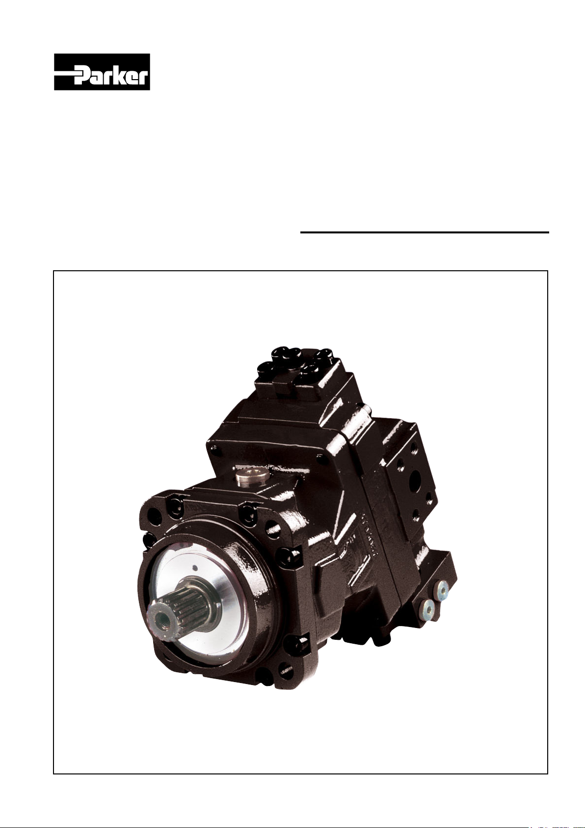
1. End cap
2. Servo control valve
3. Setting piston
4. Valve segment
5. Cylinder barrel
6. Spherical piston with
laminated piston ring
7. Synchronizing shaft
8. Heavy-duty roller bearings
9. Bearing housing
10. Output shaft
12345678910
3
Parker Hannin
Pump and Motor Division
Trollhättan, Sweden
HY30-5506-M1/UK
Service Manual
Series V12
HY30-5506-M1/UK
Service Manual
Series V12
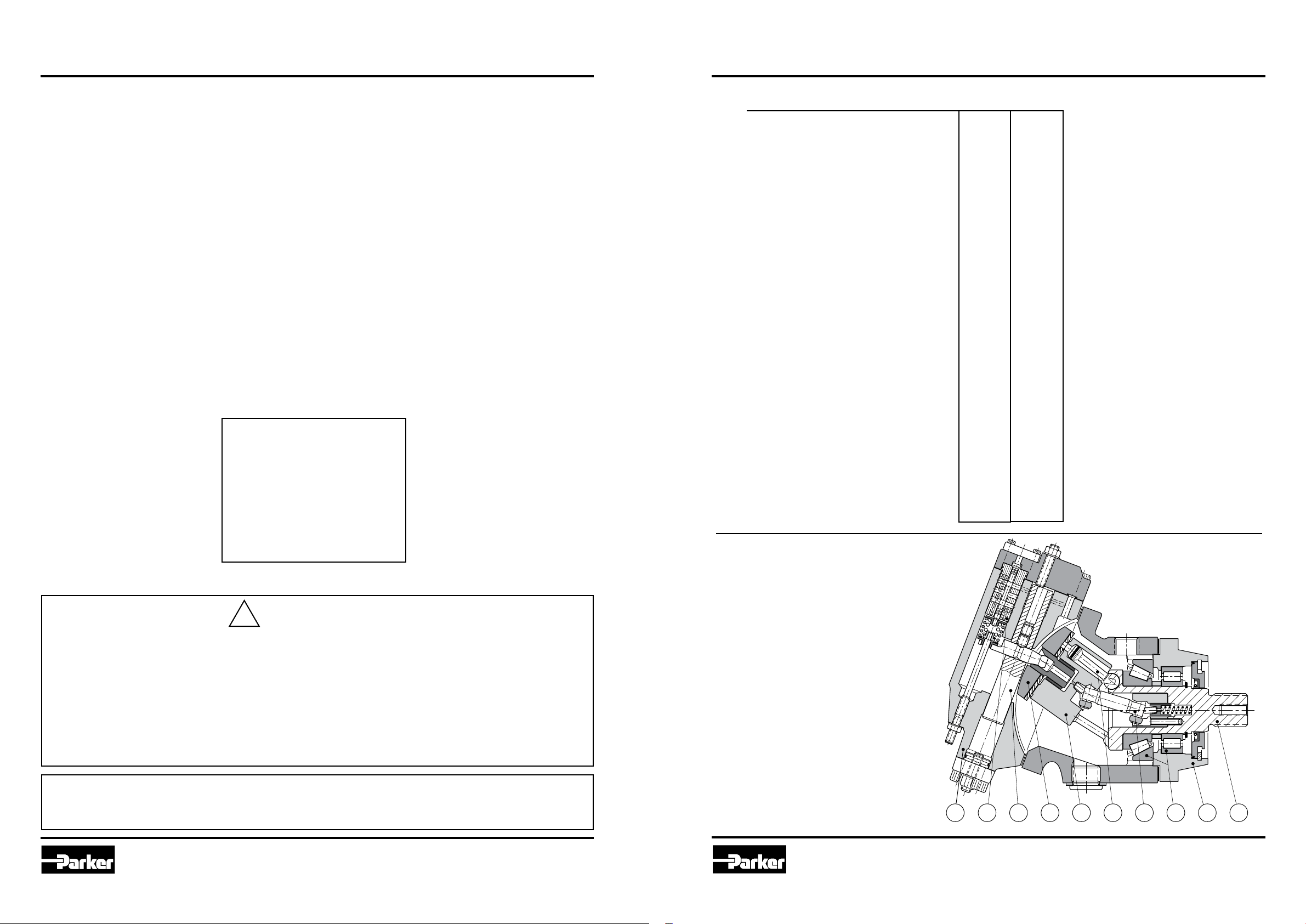
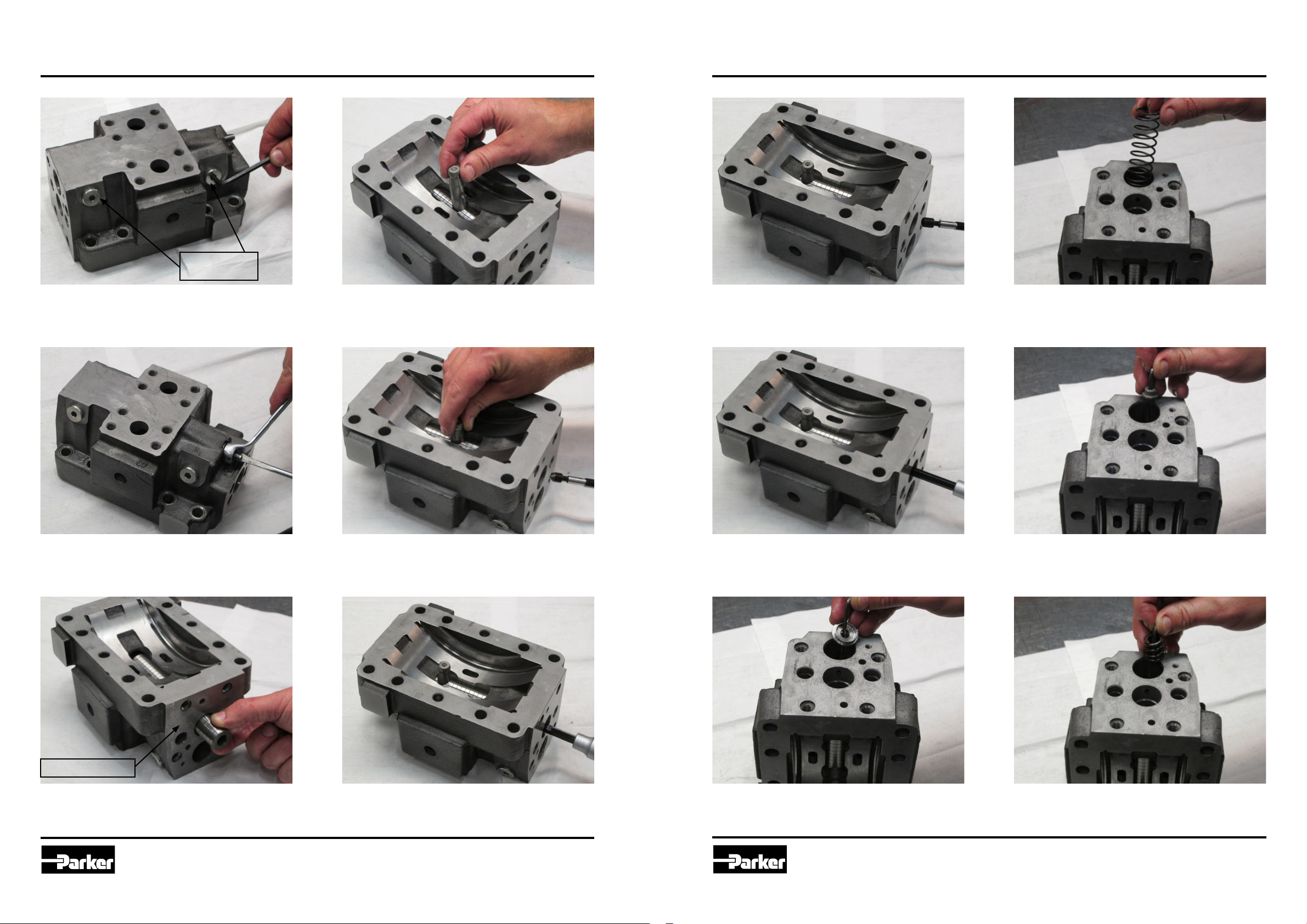
Assembling, shaft package
1. Press down the big tappered roller bearing
and the inner ring for the roller bearing in two
steps. Note! On V12-060 there is a distance
between the bearings.
4. Assemble the shim.
Assembling, shaft package, cylinder barrel, joint shaft and cover
7. Press down the shafts seal in the seal carrier and assemble the retaining ring.
10. Assemble the sliding plate.
2. Press down the roller bearing with the text
upwards into the ange and assemble it on
the shaft package.
3. Assemble the bearing ring with the text
downwards.
5. Assemble the retaining ring. Make sure
it is all the way into the groove. Check the
pre-load of the bearings, not to tight and no
back-lash.
6. Assemble the O-ring.
4
Parker Hannin
Pump and Motor Division
Trollhättan, Sweden
8. Assemble the seal carrier with shaft seal
and the retaining ring. Make sure it is all the
way into the groove.
9. Assemble the guide pins.
11. Assemble the joint rollers on the joint
shaft. Make sure the step on the joint rollers
is tted inwards.
12. Assemble the displacement setting screw,
seal nut and the O-ring.
5
Parker Hannin
Pump and Motor Division
Trollhättan, Sweden
HY30-5506-M1/UK
Service Manual
Series V12
HY30-5506-M1/UK
Service Manual
Series V12
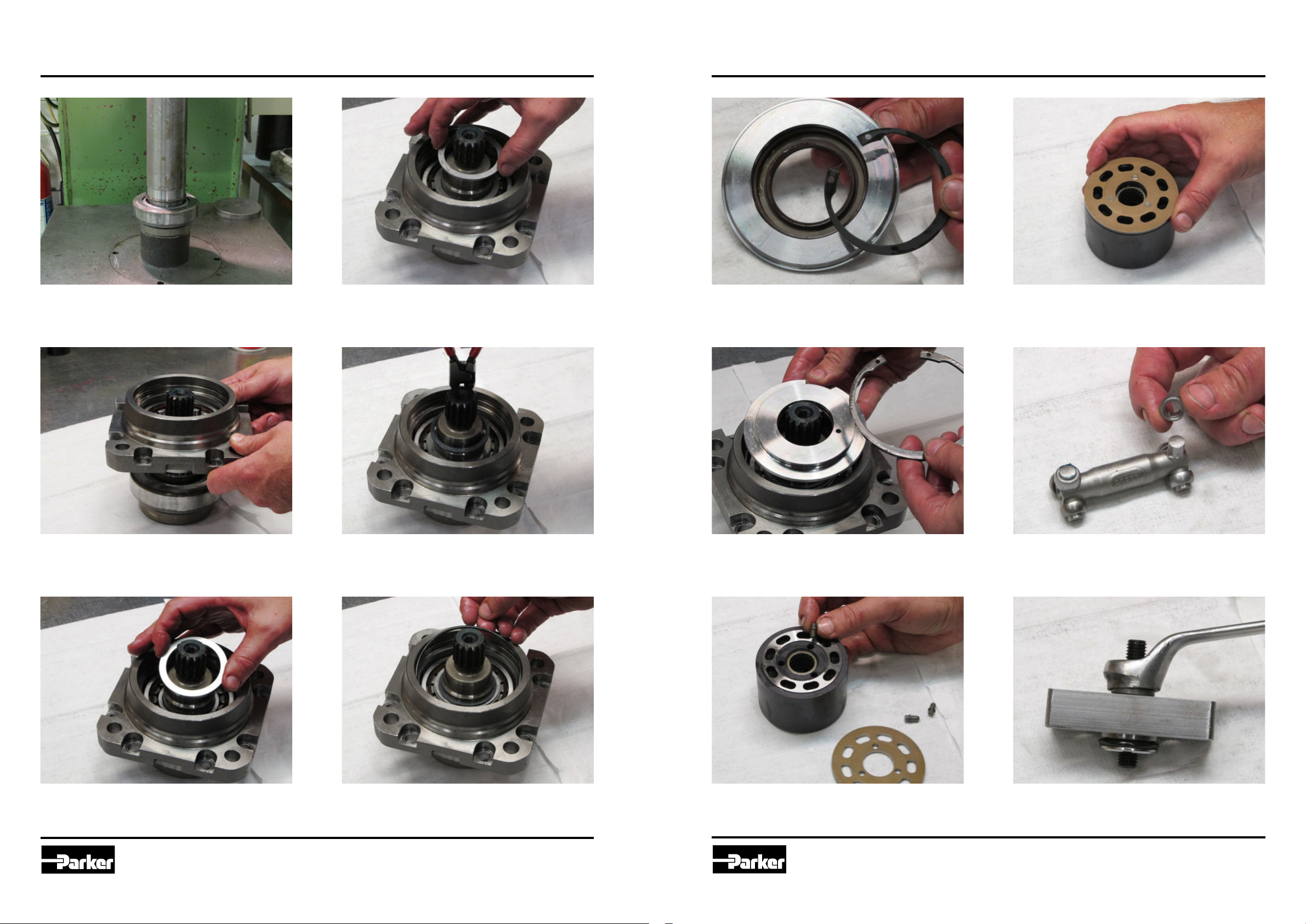
Assembling, control cover
DIN 38±8 Nm
SAE 25±5 Nm
DIN 13±3 Nm
(AHI-I)
13. Assemble the O-rings and plugs that are
required for the specic control cover. AH-
control is shown in the picture.
DIN 38±8 Nm
SAE 25±5 Nm
16. Assemble the hexagon plug.
12±3 Nm
Narrow side
Assembling, control cover, New version without valve cones and valve guides
DIN 38±8 Nm
SAE 25±5 Nm
A. Assemble the O-rings and plugs that are
required for the specic control cover. AH-
control is shown in the picture.
The control cover shown in picture is bidirectional.
DIN 38±8 Nm
SAE 25±5 Nm
DIN 13±3 Nm
(AHI-I)
14. Assemble the control piston in the AHhousing.
15. Assemble the O-ring.
17. Assemble the AH-housing. The narrow
side against X5.
18. Put some grease on the guide pin and
assemble it in the control cover.
6
Parker Hannin
Pump and Motor Division
Trollhättan, Sweden
B. Assemble the check balls.
C. Assemble the control cover and torque
the screws to 65±10 Nm for V12-60, -80
and -110. 105±20 Nm for V12-160.
7
Parker Hannin
Pump and Motor Division
Trollhättan, Sweden
HY30-5506-M1/UK
Service Manual
Series V12
HY30-5506-M1/UK
Service Manual
Series V12
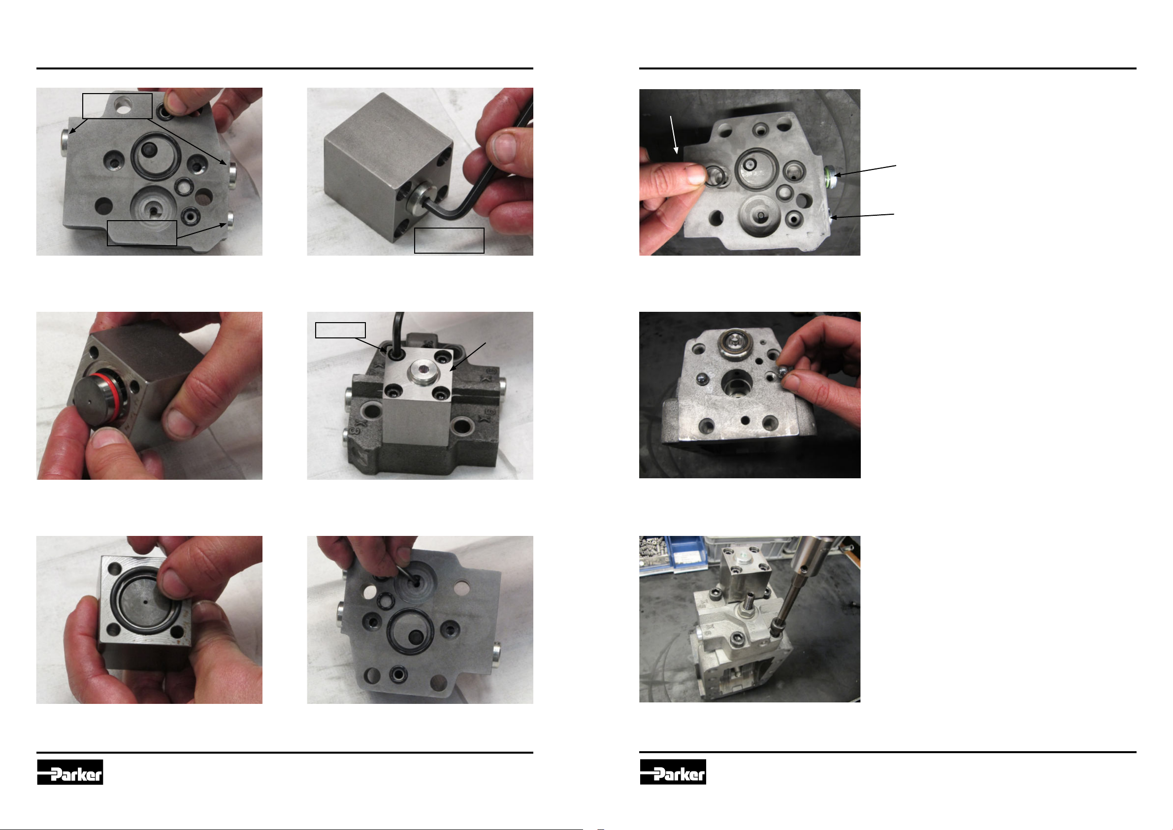
Assembling, end cap
DIN 38±8 Nm
SAE 25±5 Nm
19. Assemble the hexagon plugs.
22. Assemble the companion pin in the setting piston. Make sure the location hole is
against the control cover side.
Assembling, end cap
25. Assemble the set screw with the at end.
28. Assemble the modulating spring.
20. Assemble the adjusting screw and seal
nut.
Control cover side
21. Assemble the setting piston in the end
cap. Make sure the thread is against the control cover side.
23. Assemble the set screw with the pointed
end. Make sure that it hits the location hole in
the companion pin.
24. Torque the set screw to 14±4 Nm.
8
Parker Hannin
Pump and Motor Division
Trollhättan, Sweden
26. Torque the set screw to 26±6 Nm. Move
the companion pin back and forward to make
sure it moves smooth.
27. Assemble the spring guide. Use a long
allen key to locate the spring guide.
29. Assemble the spring seat.
30. Assemble the threshold spring.
9
Parker Hannin
Pump and Motor Division
Trollhättan, Sweden
 Loading...