

Page 1

LCD TV 19”
TLU195HB
Page 2
1. Caution
Caution
CAUTION
RISK OF ELECTRIC SHOCK
DO NOT OPEN
The lightning flash with arrowhead symbol, within an equilateral triangle, is
intended to alert the user to the presence of uninsulated “dangerous voltage”
within the product’s enclosure that may be of sufficient magnitude to constitute a
risk of electric shock to persons.
The exclamation point within an equilateral triangle is intended to alert the user to
the presence of important operating and maintenance (servicing) instructions in
the literature accompanying the appliance.
Precautions During Servicing
1. In addition to safety, other parts and assemblies are specified for conformance
with such regulations as those applying to spurious radiation. These must also be
replaced only with specified replacements.
Examples: RF converters, tuner units, antenna selection switches, RF cables,
noise-blocking capacitors, noise-blocking filters, etc.
2. Use specified internal Wiring. Note especially:
1) Wires covered with PVC tubing
2) Double insulated wires
3) High voltage leads
3. Use specified insulating materials for hazardous live parts. Note especially:
1) Insulating Tape
2) PVC tubing
3) Spacers (insulating barriers)
4) Insulating sheets for transistors
5) Plastic screws for fixing micro switches
4. When replacing AC primary side components(transformers, power cords, noise
blockin capacitors, etc.), wrap ends of wires securely about the terminals before
soldering.
TLU195HB
1
Page 3
Caution
5. Make sure that wires do not contact heat generating parts (heat sinks, oxide metal film
resistors, fusible resistors, etc.)
6. Check if replaced wires do not contact sharply edged or pointed parts.
7. Make sure that foreign objects (screws, solder droplets, etc.) do not remain inside the
set.
MAKE YOUR CONTRIBUTION TO PROTECT THE ENVIRONMENT
Used batteries with the ISO symbol
for recycling as well as small accumulators(rechargeable batteries), mini-batteries
(cells) and starter batteries should not be thrown into the garbage can.
Please leave them at an appropriate depot.
WARNING:
Before servicing this TV receiver, read the SAFETY INSTRUCTION and PRODUCT
AFETY NOTICE.
SAFETY INSTRUCTION
The service should not be attempted by anyone unfamiliar with the necessary
instructions on this apparatus. The following are the necessary instructions to be
observed before servicing.
1. An isolation transformer should be connected in the power line between the receiver
and the AC line when a service is performed on the primary of the
transformer of the set.
2. Comply with all caution and safety related provided on the back of the cabinet, inside
the cabinet, on the chassis or LCD panel.
3. When replacing a MAIN PCB in the cabinet,always be certain that all protective are
installed properly such as control knobs,adjustment covers or shields, barriers, isolation resistor networks etc.
4. When servicing is required, observe the original lead dressing. Extra precaution should
be given to assure correct lead dressing in the high voltage area.
5. Keep wires away from high voltage or high tempera ture components.
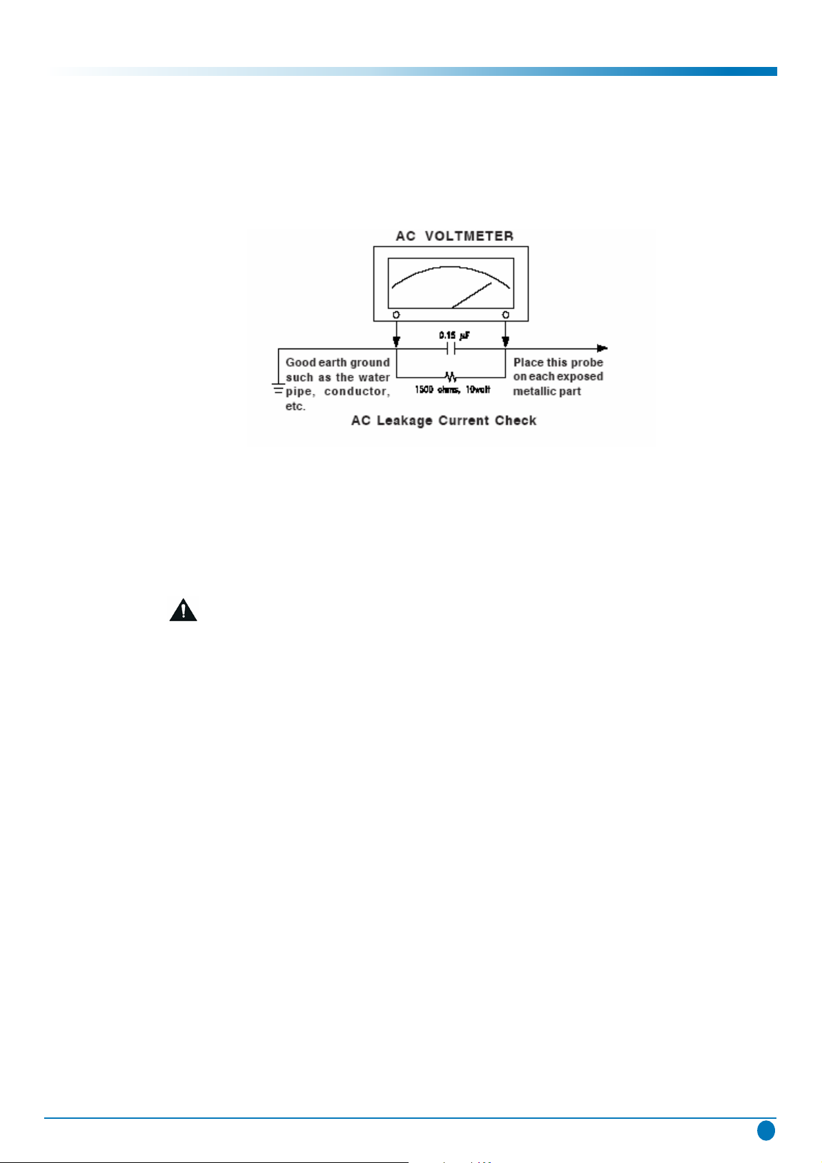
6. Before returning the set to the customer,always perform an AC leakage current check
on the exposed metallic parts of the cabinet,such as antennas, terminals,screwheads,
metal overlay, control shafts, etc., to be sure the set is safe to operate without danger
of electrical shock. Plug the AC line cord directly to the AC outlet (do not use a line
isolation transformer during this check). Use an AC voltmeter having 5K ohms volt sensitivity or more in the following manner.
Connect a 1.5K ohm 10 watt resistor paralleled by a 0.15µF AC type capacitor,
between a good earth ground (water pipe, conductor etc.,)and the exposed metallic
parts, one at a time.Measure the AC voltage across the combination of the 1.5K ohm
resistor and 0.15 uF capacitor. Reverse the AC plug at the AC outlet and repeat the AC
voltage measurements for each exposed metallic part.The measured voltage must not
exceed 0.3V RMS.
converter
TLU195HB
2
Page 4
safety
Caution
This corresponds to 0.5mA AC. Any value exceeding this limit constitutes a potential
shock hazard and must be corrected immediately.
The resistance measurement should be done between accessible exposed metal parts
and power cord plug prongs with the power switch "ON". The resistance should be
more than 6M ohms.
PRODUCT SAFETY NOTICE
Many electrical and mechanical parts in this apparatus have special safety-related
characteristics.
These characteristics are offer passed unnoticed by visual spection and the protection
afforded by them cannot necessarily be obtained by using replacement components
rates for a higher voltage, wattage, etc.
The replacement parts which have these special safety characteristics are identified by
marks on the schematic diagram and on the parts list.
Before replacing any of these components,read the parts list in this manual carefully.
The use of substitute replacement parts which do not have the same
characteristics as specified in the parts list may create shock, fire, or other hazards.
Must be sure that the ground wire of the AC inlet is connected with the ground of the
apparatus properly.
TLU195HB
3
Page 5
2. Features
Features
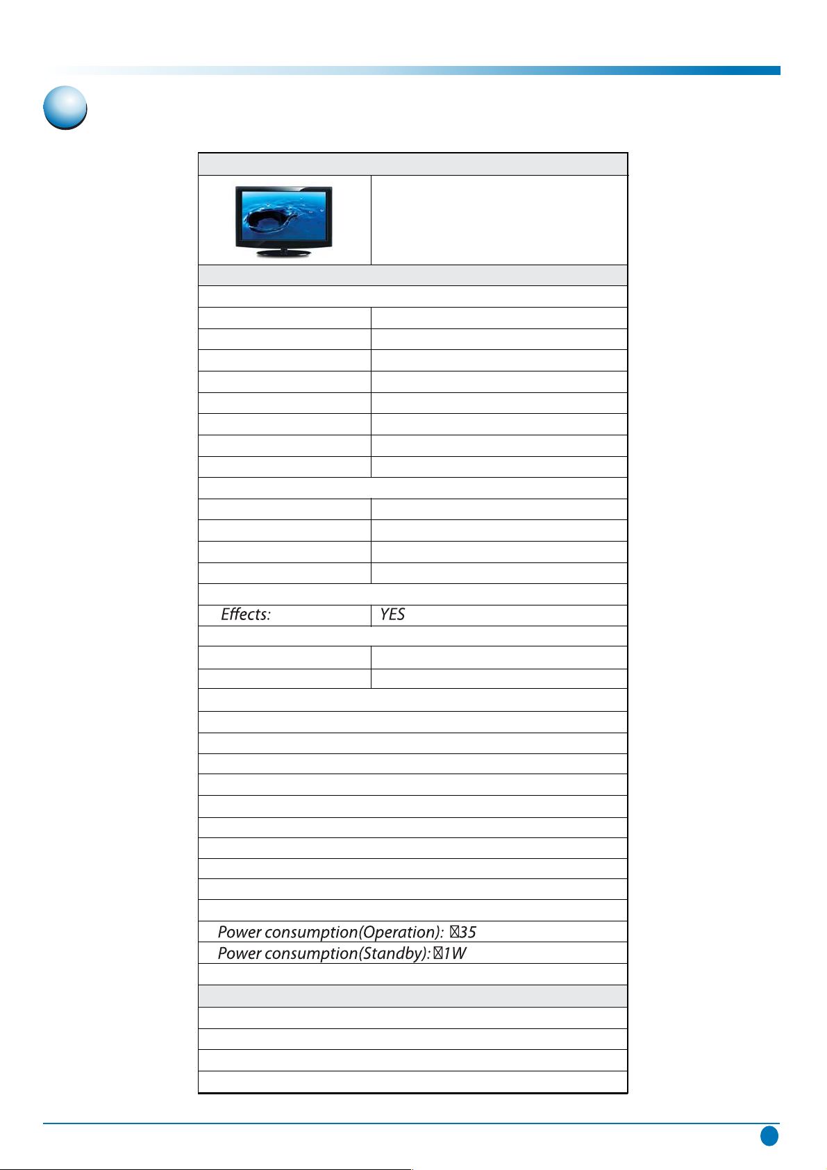
LCD TV SPECIFICATIONS SHEET
MODEL NO.: TLU195HB
DESCRIPTION: 18.5" HD LCD TV
SPECIFICATION
• PANEL
Display type: 18.5" HD TV
Aspect ratio: 16:9
Resolution: 1366*768
Brightness: 300cd/m2
Contrast: 800:1
Viewing angle: 170°X 170°
Maximum colors: 16.7M
Response time: 5ms
• AUDIO
Audio system: B/G,D/K,I,L/L'
Stereo sound: NICAM(Europe)
Max. Audio Output: 2×5W
Equalizers: YES(5 Modes)
• COLOUR: BLACK
• VIDEO: CONVENIENCE
Video system: PAL, SECAM, Progressive Scan: YES
Video IN: PAL,Secam,Nicam HD Ready: YES
• CONNECTIVITY
Pan-European Teletext: 1000
AV IN: 1 / Picture Status / Memory: YES
SCART: 1 / 16:9/4:3 Switching / YES
Antenna: 1 / DVB-T / Optical
Scart: 1 / PC Resolutio: VGA/SVGA/×GA/W×GA
VGA(D-Sub 15pin) / 1
PC Audio In: 1
HDMI+HDCP: 1 Solution: MTK8223
Head Phone Jack: 1
• POWER
Power Requirement: 100-240 50/60Hz
• ACCESSORIES
Remote controller(English): YES
Wall-mount Bracket: OPTIONAL
Stand: YES
TLU195HB
4
Page 6
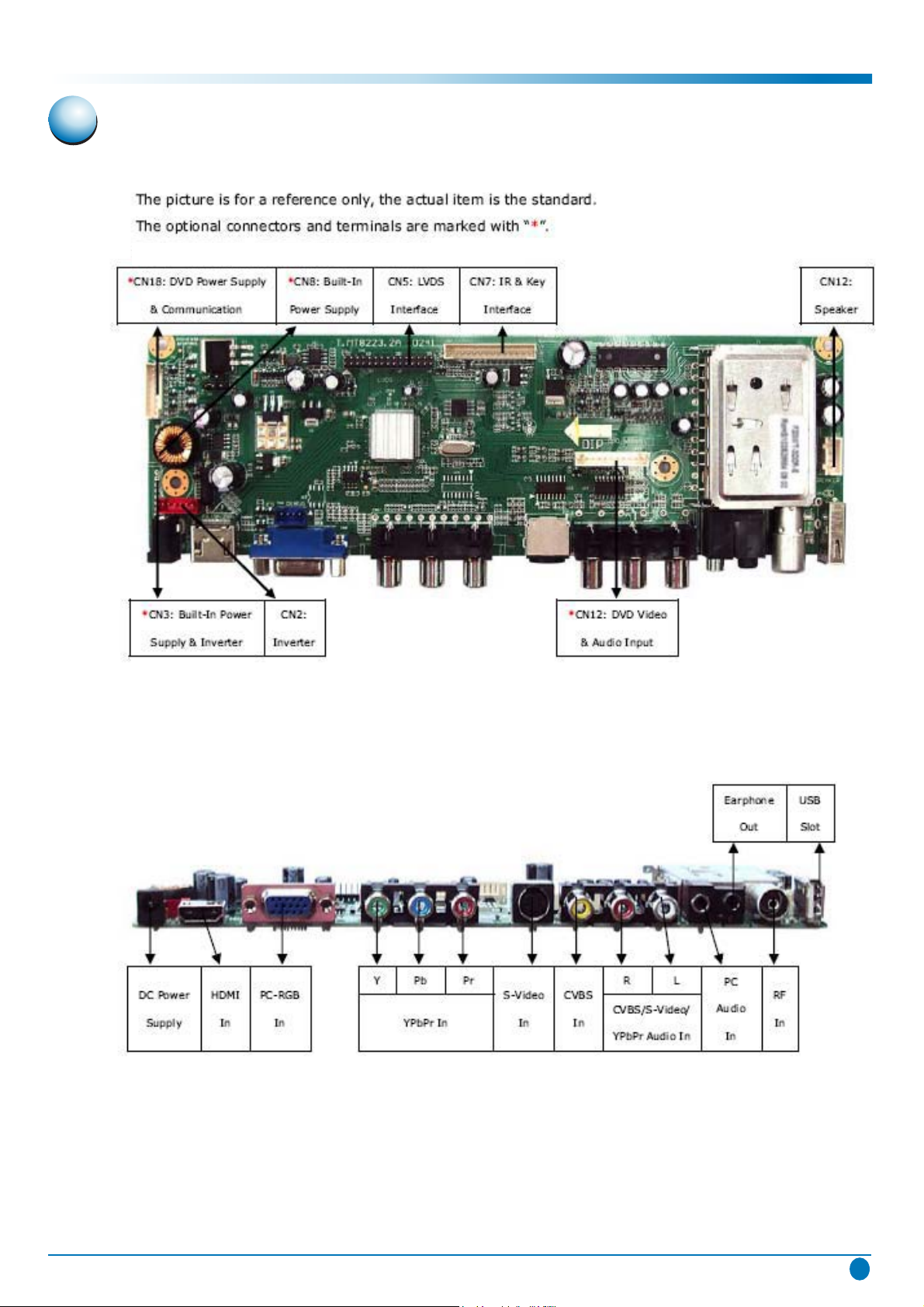
3. Function Layout
Top View
Function Layout
Front View
TLU195HB
5
Page 7
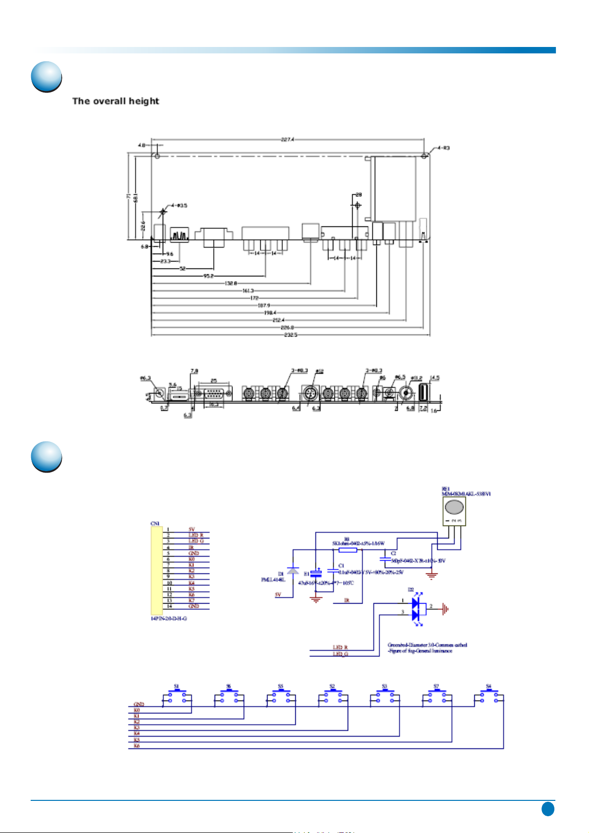
4. Diagram Schematic Dimension
Diagram Schematic Dimension
5. Schematic of Key & Ir Board
TLU195HB
6
Page 8
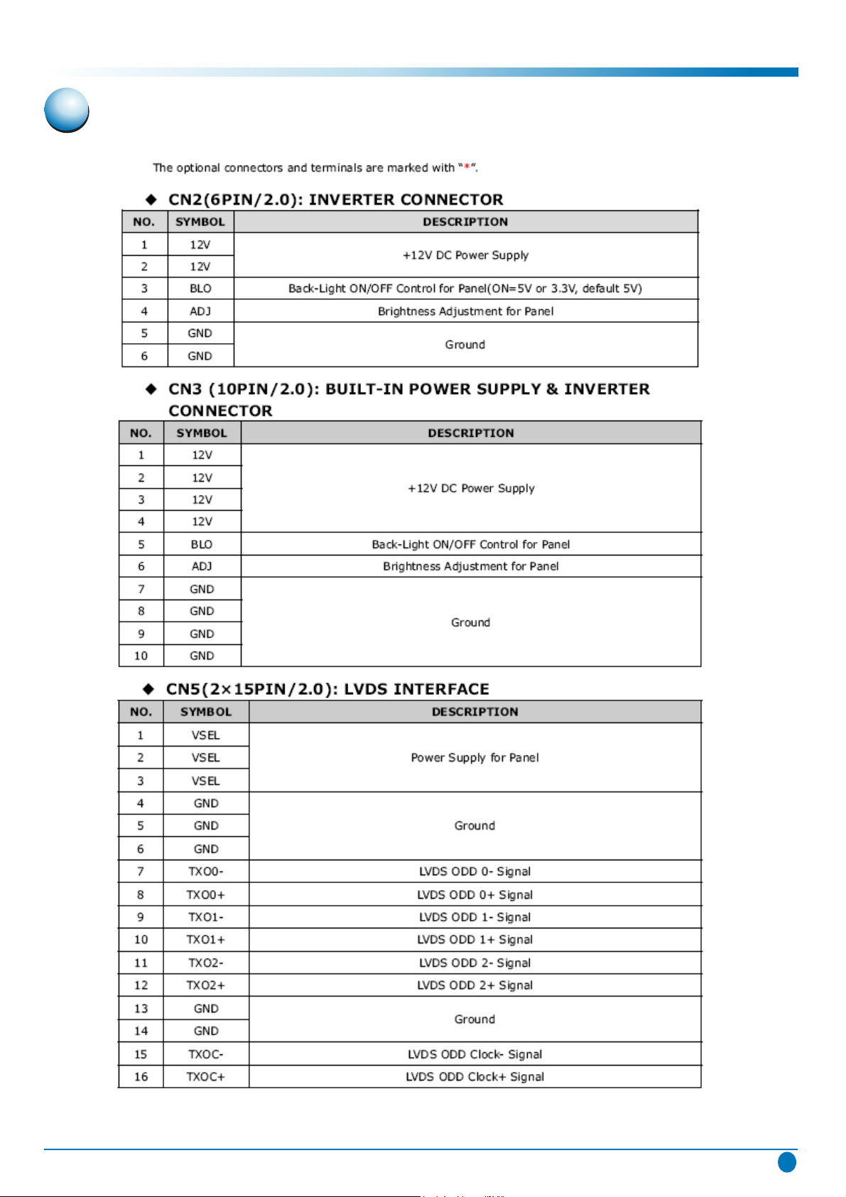
6. Interface Definition
Interface Definition
TLU195HB
7
Page 9

Interface Definition
TLU195HB
8
Page 10

Interface Definition
TLU195HB
9
Page 11

7. Remote Control Unit
Remote Control Unit
TLU195HB
10
Page 12

8. Circuit Diagram
1 BLOCK DIAGRAM
2. circuit(SCH)
1. BLOCK DIAGRAM
Circuit Diagram
TLU195HB
11
Page 13

2. Circuit(SCH)
Double click to view it.
Circuit Diagram
TLU195HB
12
Page 14

Circuit Diagram
TLU195HB
13
Page 15

Circuit Diagram
TLU195HB
14
Page 16

9. Remote Control Unit
Basic Operations & Circuit Description
Main Electric Components
(1).MODULE:
There is 1 pcs panel.
(2).SIGNAL PROCESS
There are PCB including:
1 pcs Main board,
1 pcs Keypad board,
1 pcs Remote Control Receiver board
(3).POWER & Inverter board
There is 1 pcs PCB inverter.
There is 1 pcs 12V/3A DC adapter.
PCB Function
1. Power:
Convert the low DC voltage +12V to high AC voltage to drive the backlight.
2. Main(Video InterFace) board:
(1).Convert TV RF signal to video and audio signal
(2).Convert the audio to audio amplify and output to the speaker.
(3).Decode the video signal(TV,CVBS,S-VIDEO)from analog to digital signal.
Convert the Video signals(TV,CVBS,S-VIDEO) and graphics signal(HDMI VGA,
YPbPr) from internace to progressive.
(4).Convert the Digital to fit the panel display mode and output of the LVDS signal to panel.
3. KEY board
To get the main button control on LCD TV as SOURCE,MENU,CHANNEL+,CHANNEL-,
VOL+,VOL-, STANDBY functions.
4. Remote Control board
Receive the remote signal and active for the control.
PCB failure analysis
1. CONTROL:
a. Abnormal noise on screen.
b. No picture.
2. MAIN (VIDEO):
a. Lacking color, Bad color scale.
b. No voice.
c. No picture but with signals output, OSD and back light.
d. Abnormal noise on screen.
Remote Control Unit
TLU195HB
15
Page 17

Remote Control Unit
3. POWER:
No picture, no power output.
Basic opertaion of LCD - TV
1. After turning on power switch, power board sends 5Vst-by Volt to Micro Processor IC
waiting for ON signals from Key Switch or Remote Receiver.
2. When the ON signal from Key Switch or Remote Receiver is detected, Micro Processor
will send ON Control signals to Power. Then Power sends (5V,3.3V,1.8V and Vs ON)
to PCBs working. This time inverter will send signals to display back light,OSD on the
panel and start to search available signal sources.If the audio signals input, them will
be amplified by Audio AMP and transmitted to Speakers.
3. If some abnormal signals are detected (for example: over volts, over
temperature and under volts), the system will be shut down by Power off.
current,over
TLU195HB
16
Page 18

10. Trouble shooting
Service
LCD TV Trouble shooting
NOTICE: Before repair the board,make sure the software is correct or upgrade the
correct software.
Warning:If upgrade fail,such as power off during upgrading,the flash rom must be
replaced.
Trouble shooting
POWER SUPPLY TROUBLE
TLU195HB
17
Page 19

Display Trouble (Exceptional Screen)
Trouble shooting
Display Trouble (White Screen)
TLU195HB
18
Page 20

Audio Trouble ( No sound)
Trouble shooting
Display Trouble (Black Screen)
TLU195HB
19
Page 21

Function Trouble (TV video)
Trouble shooting
Function Trouble (PC)
TLU195HB
20
Page 22

Audio Trouble ( HDMI; CVBS)
Trouble shooting
Function Trouble (SCART; YPbP; and so on)
TLU195HB
21
Page 23

11. Exploded View
Exploded View
TLU195HB
22
Page 24

 Loading...