

Page 1
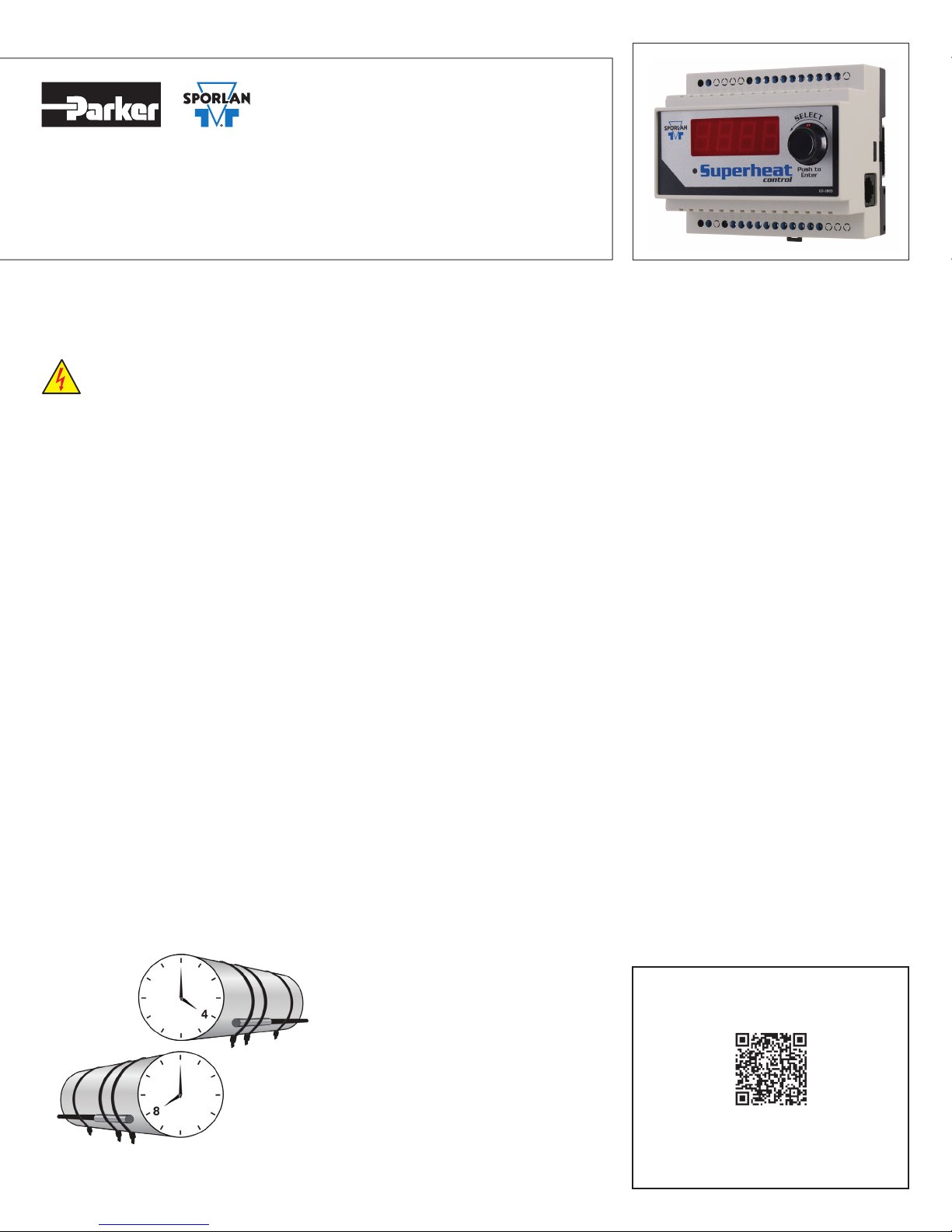
Superheat Control
Quick Reference Guide
SD-324/72016 Controller v. J
The Sporlan Superheat Control should be installed only by a qualified professional. All other system components (valves and sensors)
should be supplied by Sporlan to ensure compatibility and proper operation. There are no user-serviceable components inside the controller. Opening the case will void the warranty.
Use caution when working around high voltage components.
Safety covers should be used for personal safety on high voltage panels.
Tools required:
• Small flat screwdriver for terminals
• Cordless screwdriver
• Phillips and flat screwdrivers
• Needle-nose pliers
• Wire cutters
• Two #8 x ½” self-tapping screws to
mount the DIN rail
1. INSTALLATION
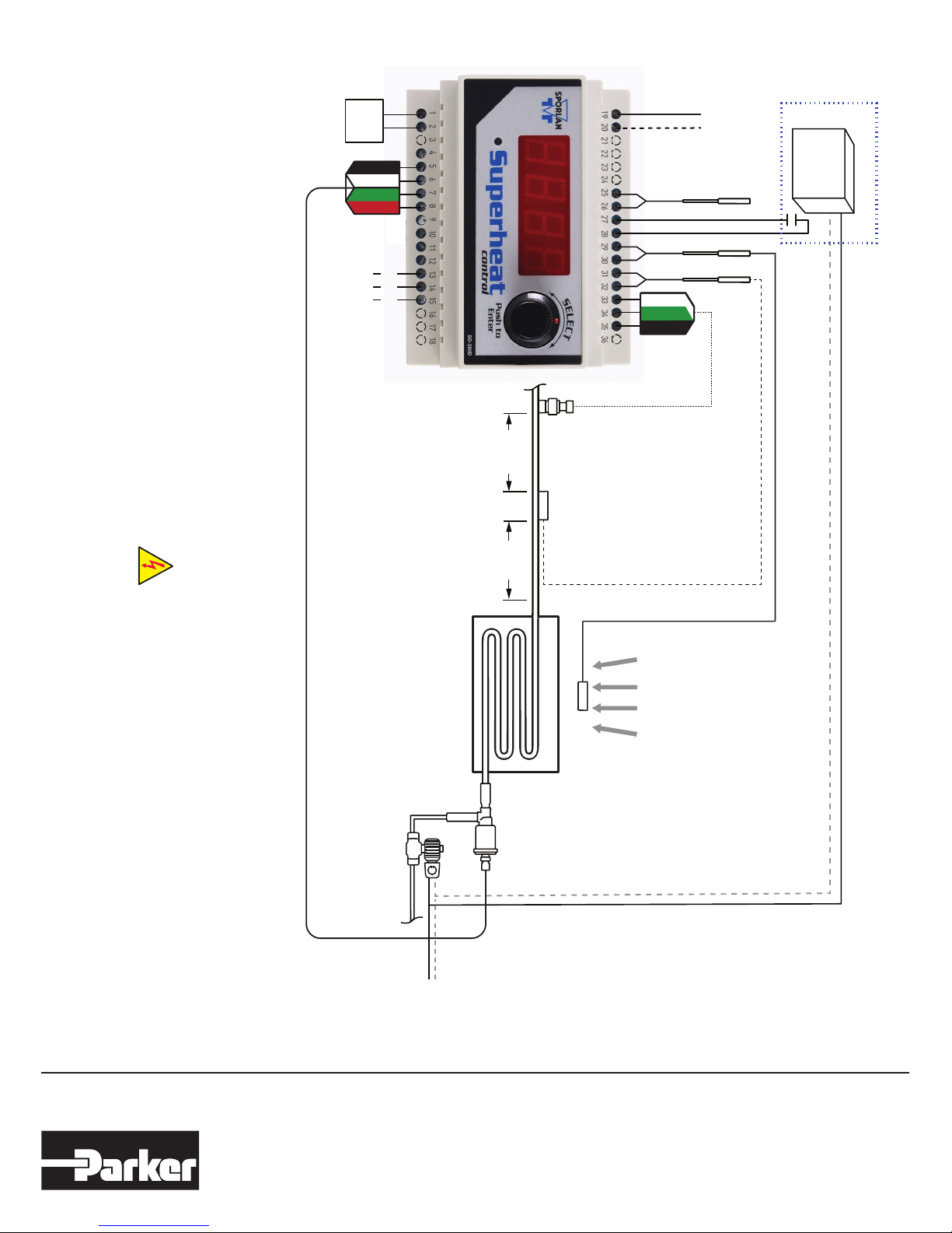
Reference diagram on back of this guide.
1. Mount the controller in a rain-tight,
protected location using the DIN rail.
The suggested mounting area is 10
inches high and 5 inches wide, depth is
3 inches.
2. Mount the suction temperature sensor to
the suction line after the heat exchanger
following the instructions provided with
the sensor. Connect the non-polarized
sensor wires to terminals 31 and 32.
Maximum torque on screw terminals
is 3.5 in-lbs.
3. Mount the pressure transducer on the
suction line near the suction temperature sensor, positioned at 12 o’clock.
Connect the wires to terminals 33, 34,
and 35. Ensure that any splices are
properly connected.
4. Connect terminals 27 and 28 to a digital
input. A short or a closed contact from
an external relay will close the valve for
pump down.
5. Connect the Electric Expansion Valve
(EEV) wires to terminals 5, 6, 7, and 8.
6. Connect the optional case temperature
sensor wires to terminals 29 and 30.
The sensor is not polarized.
7. Connect power to terminals 1 and 2.
Transformer requirements are 24 volts
AC at 40 VA, Class II.
2. SETUP
Enter values for six system variables. The
EEV is closed upon startup and the system
will not operate until completing setup.
Once powered up, the controller will display the firmware versions and then the
first variable to set.
1. Set StEP, Step Motor Stroke. Press and
then turn the SELECT knob to select
the correct number of steps for the
EEV being used. Default is 2500.
Press the SELECT knob again to save
the value. The next variable displays.
2. Set reFr, Refrigerant. Select the
actual refrigerant used in the system.
Default is 404A.
3. Set tt4P, Temperature Sensor Type.
Select 2K or 3K. Default is 2K.
4. Set Pt4P, Pressure Sensor Type. Select
Absolute or Gauge, following the steps
above. Default is Gauge.
5. Set Un_t, Temperature Units. Select
Fahrenheit or Celsius. Default is
Fahrenheit.
6. Set Un_p, Pressure Units. Select PSI ot
Bar. Default is PSI.
3. OPERATION
For further system tuning, adjust parameter
setpoints as described below and in Bulletin
100-50-5.1.
1. Enter the Parameter Menu: Hold down
the SELECT knob for 5 seconds.
Rotate the knob to enter the password
“111 ” and press the SELECT knob
again.
2. To change a parameter, rotate the
SELECT knob to the desired parameter and press the SELECT knob. The
default parameter value will display.
3. Turn the SELECT knob to change the
parameter value and then press the
SELECT knob to save the value and
return to the Parameter Menu.
4. After all parameters are set, rotate the
SELECT knob to “ESC” and press the
SELECT knob again to save all changes. Observe the system for superheat
operation.
Note: The Parameter Menu times out
after 60 seconds of inactivity and
all changes entered will be lost.
Note: Not all refrigeration systems are
designed alike. See the Kelvin II
Installation and Operation Manual
to adjust the settings according to
the specific needs of the system.
Sporlan Superheat Control
Installation and Operation Manual
Temperature sensor should be mounted at
either 4 or 8 o’clock, on a free-draining line.
Setup is complete. The controller will
display SvpH. The controller is now in the
Process Values Menu. Rotate the knob to
view the values.
For detailed instructions,
scan this QR code or go to
www.sporlanonline.com/electronic-controls
and download Bulletin 100-50-5.1
Page 2
Rated 240v, 3A
Internal Relay
AC/DC
24V
Black
Black
White
Ground
A+
B-
White
Green
Green
Red
Red
RS485
1”- 2” ideal
minimize
Suction Temperature
Sensor
Pressure
Transducer
For safety information, see the Safety Guide at www.parker.com/safety or call 1-800-CPARKER.
For 500 Step Sporlan Unipolar Valve
4 -> Gray Wire
5 -> Orange Wire
6 -> Yellow Wire
7 -> Red Wire
8 -> Black Wire
*T3 can be used as an Auxillary Temperature Input or a Pumpdown Input signal.
Note: Piping and sensor insulation is not shown.
Load
Line
Aux. Temp. (T4)
Dry Contacts (T3)
Room Temp. (T2)
Evap. Outlet Temp. (T1)
White
White
Green
Green
Black
Black
*
Pumpdown
Relay
Note: Use caution when working
around high voltage components.
Solenoid Valve
Liquid Line
L1
10”-14”
Refer to the evaporator manufacturer’s
installation/orientation instructions.
Evaporator
EEV
L2
Return Air
SD-324, July 2016 supersedes SD-324, October 2012 and all prior publications.
Parker Hannin Corporation
Sporlan Division
206 Lange Drive • Washington, MO 63090 USA
phone 636 239 1111 • fax 636 239 9130
www.sporlan.com
SD-324 / 72016 © 2016 Parker Hannin Corporation.
 Loading...