

Page 1
Parker Hannifin GmbH & Co. KG
Tube Fittings Division Europe
Am Metallwerk 9, 33659 Bielefeld
Phone +49
-
521-4048
-0Fax +49
-
521-4048
-
4280
SensoControl
®
Operating
Instruction
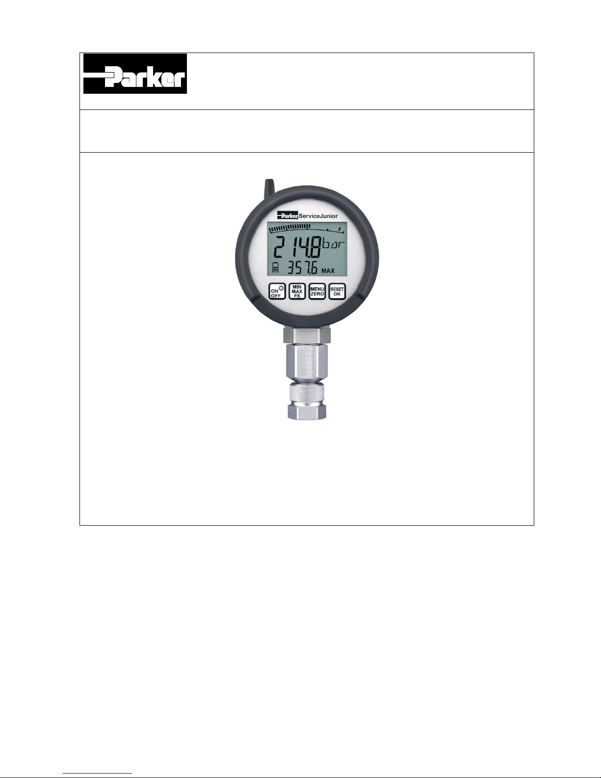
ServiceJunior
wireless
Please read carefully before use!
Page 2

Contents
1
Introduction
................................
................................
................................
................
1
1.1
Notes on safety/production selection
................................
................................
...........
1
1.2
Device versions and range of delivery
................................
................................
.........
1
1.3
Send and receive with wireless radio interface
................................
............................
1
1.4
Scanning rate a
nd memory p
rinciple
................................
................................
............
2
2
Commissioning
................................
................................
................................
..........
3
2.1
Replacing the batteries
................................
................................
................................
3
3
Fun
ctions and keys
................................
................................
................................
....
4
3.1
Display Mode
................................
................................
................................
...............
5
3.2
Menu Functions
................................
................................
................................
...........
5
4
Conn
ection to the hydraulics
................................
................................
...................
75Operating ServiceJunior
wireless
................................
................................
............
8
5.1
Turning on (ON)
................................
................................
................................
...........
8
5.2
Turn off (OFF)
................................
................................
................................
..............
9
5.3
Turn on back light
................................
................................
................................
........
9
5.4
MIN/MAX Display
................................
................................
................................
.........
9
5.5
FS Full Scale Display
................................
................................
................................
...95.6
Erasing the MIN/MAX values
................................
................................
.......................
9
5.7
OFL Display
................................
................................
................................
.................
9
5.8
Zero Point correction (ZERO)
................................
................................
....................
10
5.9
Resetting the zero point correction
................................
................................
............
10
5.10
Aut
omatic Switch Off
................................
................................
...............................
11
5.11
Changing the Unit
................................
................................
................................
...125.12
Filter Settings
................................
................................
................................
..........
13
5.13
Display device address
................................
................................
...........................
13
5.14
Data Memory Function
................................
................................
............................
14
5.15
Set up
REC time
Function
................................
................................
......................
15
5.16
Delete D
ata Memory
................................
................................
...............................
16
5.17
Setup Function REC
AUTO
................................
................................
....................
17
6
Technical Data
................................
................................
................................
..........
18
Page 3
page1of
21
1
Introduction
The
ServiceJunior
wireless
is a digital manometer featuring a MIN/MAX display function.
Full scale (FS) accuracy is ± 0.5% based on the
upper limit of the measurement range.
Dynamic pressure peaks are measured at a scannin
g rate of 10
ms (100 measurement
values/second). The MIN/Max memory is
continuously updated and rewritten.
1.1
Notes on safety/production selection
The correct functioning of the
ServiceJunior
wireless
can only be guaranteed
when the
specifications detailed
in these operation instructions
are adhered to.
In particular, specifications relating to the
permitted upper limit of the measurement range as well as
the
permissible temperature range must be observed.
For repairs or calibration of the measureme
nt instruments,
please contact a
Parker sales branch.
1.2
Device versions and range of delivery
Device versions/range of delivery
Basic setting to unit ‘
b
ar’
Pressure connection, male thread G 1/4
Delivery with adapter
Range
-
1…16 bar/
0…100/0…400/
0…6
00/0…1
,
000 bar
Part No.
SCJNP
-
xxx-01-RC
1.3
Send and receive with wireless radio interface
The
ServiceJunior
wireless
operates with a bidirectional wireless interface. The operating range is
specified to 50 m. In some applications you will have
disturbance
s
based on existing interferences.
Transmitting data’s from the ServiceJunior to the PC data lost will be avoid by sending cryptic data
codes.
In the case of no or less transmission signal received,
please put the PC adapter and/
or the
ServiceJunior
wire
less
into another position. There is no risk to loose data memory content at any
time, while the data
memory needs
to be deleted by the user.
The
ServiceJunior
wireless
operates battery
powered
.
Send and transmit
data
to the PC/Notebook or receive param
eters will consume energy.
If the battery capacity will be consumed totally, no data memory content will be lost.
The data memory content operates independent from given battery capacity.
Serious malfunctions leading to personal injury
or damage
to property can result from
using the chosen product
in applications that do not comply with the specifications
or from disregarding the operating instructions.
In particular,
incorrect mounting of the manometer and the corresponding
adapter ca
n
cause the manometer to be torn
Page 4

page2of
21
1.4
Scanning rate a
nd memory principle
The
ServiceJunior
wireless
i
s running with a fast scanning rate (10 ms) in order to capture all
peaks.
Based on all scanned values, the highest reading will be sorted and saved into the data memory.
The user is able to set up two different memory functions:
REC time
(time based da
ta recording)
The memory interval will be set up automatically by selected recording time (3, 10, 30, 60 min) and
g
iven quantity of data points (5,
000).
According to a recording time of 10 min there is an interval of 120 ms (0.12 s).
Recording
Time
Inte
rval
minmss
Qty of
Readings
Data Memory
3360.0363
MAX
10
120
0.1212MAX
30
360
0.3636MAX
60
720
0.7272MAX
REC AUTO
(Long term pressure peak monitoring with trigger point)
Exceeding the trigger point (tp) data recording will be processed
.
Below the given trigger point (tp) no readings will be saved.
The memory interval (INT) can be set from 100 ms/1/10/100 s.
The scan rate is still 10 ms and can not be changed.
Example:
Memory interval „INT = 10 s“:
Running with a scan rate of 10 ms
and a memory i
n
terval of 10 s out of 1
,
000 readings the highest
(MAX) reading will be sorted and saved into data memory.
Interval
s
Qty of
Readings
Data Memory
0.110MAX
1
100
MAX
10
1.000
MAX
100
10.000
MAX
This procedure enables the user to mo
nitor pressure peaks over a long term period.
Page 5
page3of
21
2
Commissioning
The
ServiceJunior
wireless
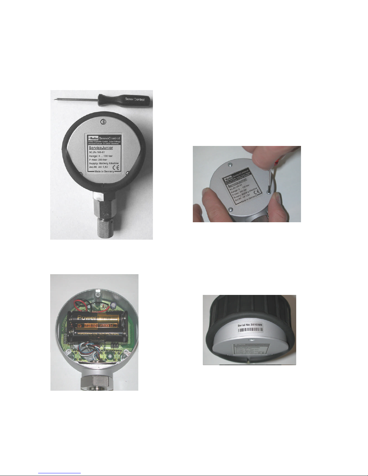
is supplied with batteries fitted. The device is
operational as soon as
it is turned on.
2.1
Replacing the batteries
A battery symbol permanently
displays the
actual
battery status.
Caution!
Turn off
the device before replacing
the
batteries. Open the
battery compartment.
Ins
ert the
new batteries as depicted.
Ensure
correct polarity of the batteries.
Batteries: 2 x 1.5 V (LR6
-
AA)
ServiceJunior
wireless
Page 6
page4of
21
3
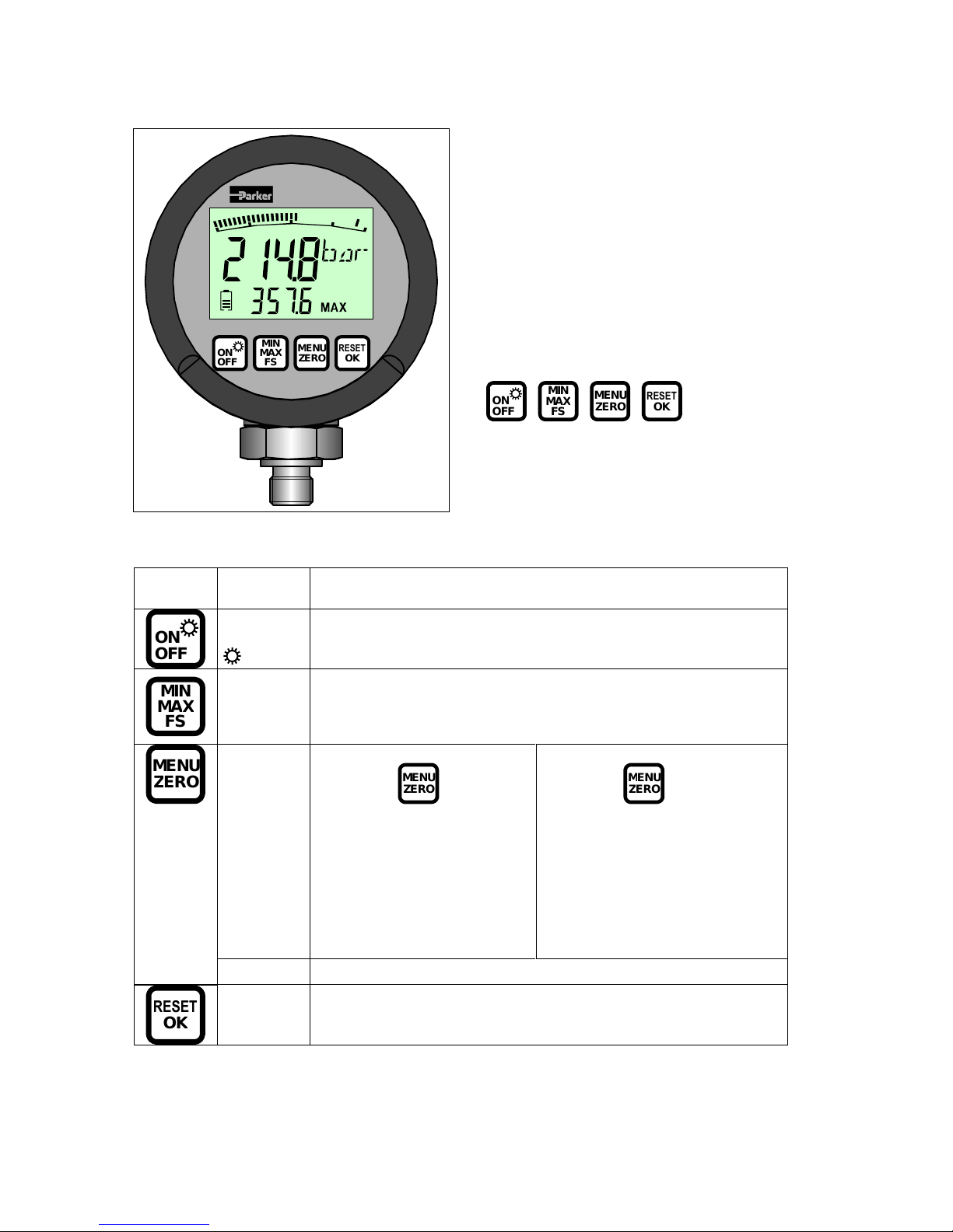
Functions and keys
Key
Function
ONOFF
ON/OFF
Turns the device on/off.
Press 2 s.
Turns on the back light function (stays on for 30 s)
MINMAXF
S
MIN
MAX
FS
Selects display unit: MIN/MAX or FS
Minimum value
Pressure pea
k
Displays the upper limit of the scale (e.g. 400 bar)
MENU
Press 2 s.
Select with
MENUZER
O
1.
Menu functions
automatic switch off
engineering units
Filter settings
Device address/
Software version
Select with
MENUZER
O
2.
REC time function
Time based data logging
Setup data recording
3.
REC Auto function
Long term data logging with
individual memory interval
MENUZER
O
ZERO
Zero point adjustment
RESET
O
K
RESET
OK
Erases MIN and MAX values from the memory
Confirms the MENU functions
ServiceJunior
ONOFFMINMAXFSMENUZERORESETO
K
Display
4 ½ digit LCD with back light function
Displays measurement values
and menu functions
‘Bar Graph’ with peak & hold fun
ction
Actual value display (15 mm)
MIN/MAX or Full Scale (FS) (8 mm)
Battery status
Keys
ONOFFMINMAXFSMENUZERO
RESET
O
K
Page 7

page5of
21
3.1
Display Mode
The actual pressure (ACT) is
indicated in the display mode. The
ACT measured value is displayed in
the corresponding unit. The
MIN, MAX or FS values is indicated in the lower part of the display.
Display
Description
bar-graph
Graphic indication of the actual pressure.
A pressur
e peak is indicated by means of a pixel
(graduation mark).
The indicated value is refreshed at intervals of
50 ms (20 measurements/s).
ACT
Indicates the actual pressure.
The indicated value is refreshed at intervals of
300 ms (3 times/s).
MIN/MAX
Indic
ates the MIN, MAX or FS value according
to setting.
The indicated value is refreshed at intervals of
300 ms (3 times/s).
FS
Full scale range (e.g. 400 bar)
Units
Indicates the chosen unit
Battery
Indicates battery status (5 segments
)
Send or Receive M
ode
REC
REC flashes when recording measurement values
(optional data logging function)
x10
Indicated value (actual indication and MIN/MAX
indication) x10
3.2
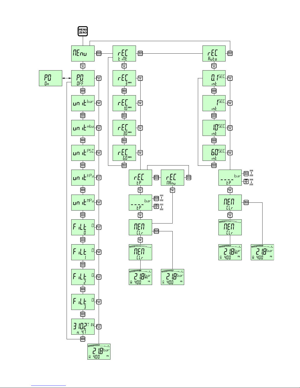
Menu Functions
Following set ups can be done within the MENU Function:
Automatic switch off ena
ble/disabled
Selection of engineering units (bar/mbar/PSI/kPa/Mpa.)
Filter settings
REC time or REC auto function
Delete data memory
By pressing the MENU key (2
s
) the desired function appears.
Skip to next function by pressing MENU again.
Confirmation
by pressing the „OK“ key.
The
ServiceJunior
wireless
returns into the display mode.
Page 8
page6of
21
RESETOKRESETOKRESETOKRESETOKRESETOKRESETOKRESETOKRESETOKRESETOKRESETOKRESETOKRESETOKRESETOKRESETOKRESETOKRESETOKRESETOKRESETOKRESETOKRESETOKRESETOKRESETOKRESETOKRESETOKRESETOKRESETOKRESETOKRESETO
K
MENUZER
O
MENUZEROMENUZEROMENUZEROMENUZEROMENUZEROMENUZEROMENUZEROMENUZEROMENUZEROMENUZEROMENUZEROMENUZEROMENUZEROMENUZEROMENUZEROMENUZEROMENUZEROMENUZEROMENUZEROMENUZEROMENUZEROMENUZEROMENUZEROMENUZEROMENUZEROMENUZEROMENUZEROMENUZER
O
MIN
MAXFS
MIN
MAXFS
o
r
Page 9
page7of
21
4
Connection to the hydraulics
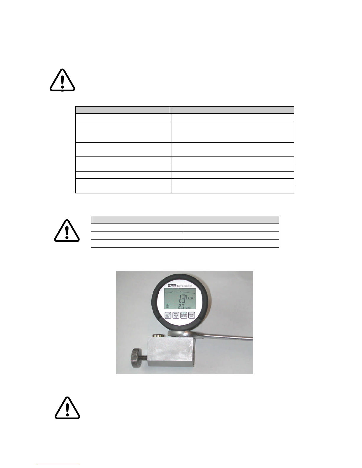
The
ServiceJunior
wireless
is
available with male thread G1/4 (BSPP) or
7/16
-
20 UNF for the
corresponding versions (bar/PSI).
Ple
ase do not do the assembly while the ServiceJunior
wireless
is
pressurized
!
Model
SCJNP
-
xxx-01-RC
Pressure port
¼ BSPP
Adapter (M16x2)
SCA
-
1/4-EMA
-3(hex size 24 = 600 bar)
(hex size 27 = 1.000 bar) pre
-
mounted
Test Hose Adapter
(M16x2) male/male
SCA-
EMA
-
3/3
Other systems
Testpoint M16x1.5
SCA
-
EMA
-
3/4
Testpoint M12,65x1.5
SCA
-
EMA
-
3/2
Testpoint Pin Lock
SCA
-
EMA
-
3/1
Observe specified t
orques when fitting the ServiceJunior
wireless
The hex size of the pressure port is 27 mm
Pressure
conne
ction
Torque
7/16
-
20 UNF
35 Nm
¼ " BSPP
3
5 Nm
When fitting directly, please ensure the
ServiceJunior
wireless
can be rotated
freely.
Safety Instructions for using 1.000 bar operating range:
The delivered adapter SCA
-
1/4-EMA
-
3 (hex size 27) is approved up to nominal
pressure of 1,000 bar.
Please pay attention to built in test points acc. to rated nominal pressure and
specified safety factor.
Page 10
page8of
21
5
Operati
ng
ServiceJunior
wireless
5.1
Turning
on (ON)
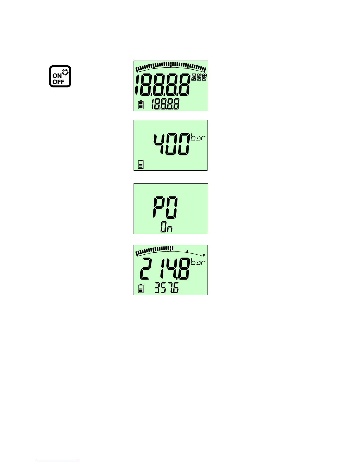
Self test running
Indication of full
-
scale range (FS)
Unit (
bar
) SCJNP
-
xxx-01-RC
MINFSMAXRECx10F
S
Auto Power Off function is active.
Power Off activates automatically
swit
ch off after 5 min.
This function can be altered in
MENU
.
MAX
ONOFF
Press
Display mode.
ACT
value
displayed
MAX
peak
Page 11
page9of
21
5.2
Turn
off (OFF)
ONOFF
Press
once
(
briefly
)
5.3
Turn on b
ack light
ONOFF
Press the
key (2 s)
The back light illumination will be switched off after 30 s.
5.4
MIN/MAX Display
The additional display line can be switched to MIN/MAX or FS format.
The scroll function indicates MIN/MA
X after the other.
To measure pressure peaks the MIN/MAX Function is in use. The MIN/MAX memory saves the
highest (MAX) and the lowest (MIN) reading. Switching off the instrument, the MIN/MAX memory will
be erased.
When running different pressure tests
one after another, the MIN/MAX memory should be deleted
(
RESET
) after every test cycle.
MIN
MAXFS
MIN/MAX and FS
value is indicated in the display
5.5
FS Full Scale Display
Displaying the upper limit of the scale (FS) is designed to increase
readability of the
bar-graph
function.
The upper limit of the measurement range is indicated numerically.
FS is indicated in sequence after MIN and MAX.
MINMAXF
S
FS
value is indicated in the display
5.6
Erasing the
MIN/MAX
values
RESET
O
K
Erases
MIN/MAX
values
5.7
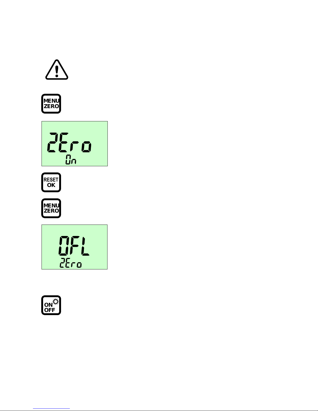
OFL Display
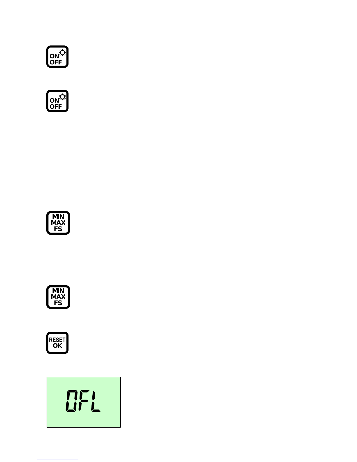
This indicates that the applied pressure
is outside given full scale range.
If the message will remain displayed,
while the
ServiceJunior
wireless
is
pressure less, please consult a Parker
Hannif
in Sales Office.
Page 12
page10of
21
5.8
Zero Poin
t
correction
(ZERO)
The zero point can be corrected manually should undesired deviations
occur when no system
pressure is being applied (atmospheric
pressure).
MENUZER
O
Press ZERO key (
briefly
)
RESET
OKMENUZER
O
5.9
Resetting the zero point correction
ONOFF
This initiates the zero point correction. The
ACT
(actual)
value is indicated in the
display as 0.0 bar.
The correction
remains active until the device is turned off.
The zero point correction sets the current ACT value t
o
zero. In order
exclude erroneous measurements, ensure
no system pressure
is
being applied when carrying out
this function.
OFL/ZEro
is displayed for 3 seconds
if the measured pressure (0
bar) is
greater than 5% of the
measurement range.
Zero point c
orrection cannot be
carried out.
Please ensure that
no system pressure
is being applied.
Turn off the device. Zero point correction is no longer
active when the device is turned off and on again.
Page 13
page11of
21
5.10
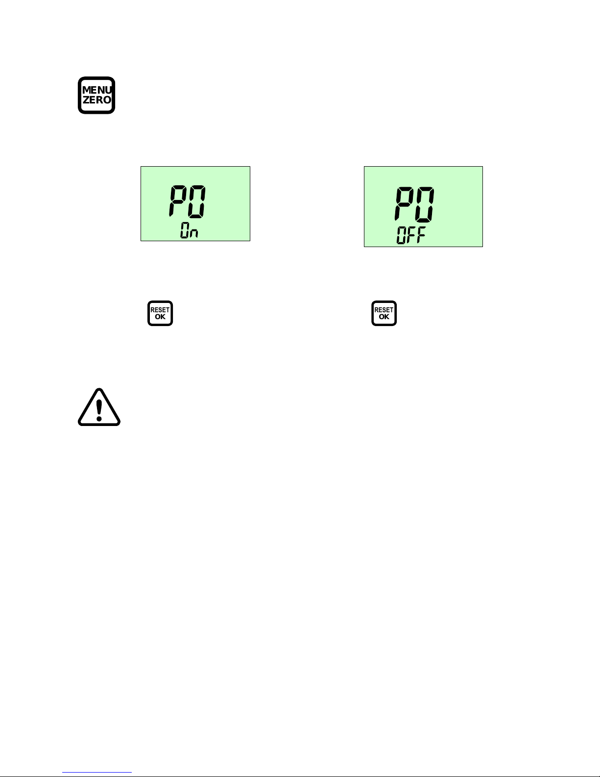
Automatic Switch Off
MENUZER
O
Press for 2 s
According to
the
ServiceJunior
wireless
configuration two different setups are possible.
The settings
Auto Power Off or Continuous operations
remain stored
and are active when the device is turned
off and on again.
Auto
Power O
ffContinuous operation
s
PO On
When
RESET
O
K
is pressed, t
he
Auto Power Off is enabled.
The device will switch off after 5 min.
PO OFF
When
RESET
O
K
is pressed, the device
must be turned off manually.
Page 14
page12of
21
5.11
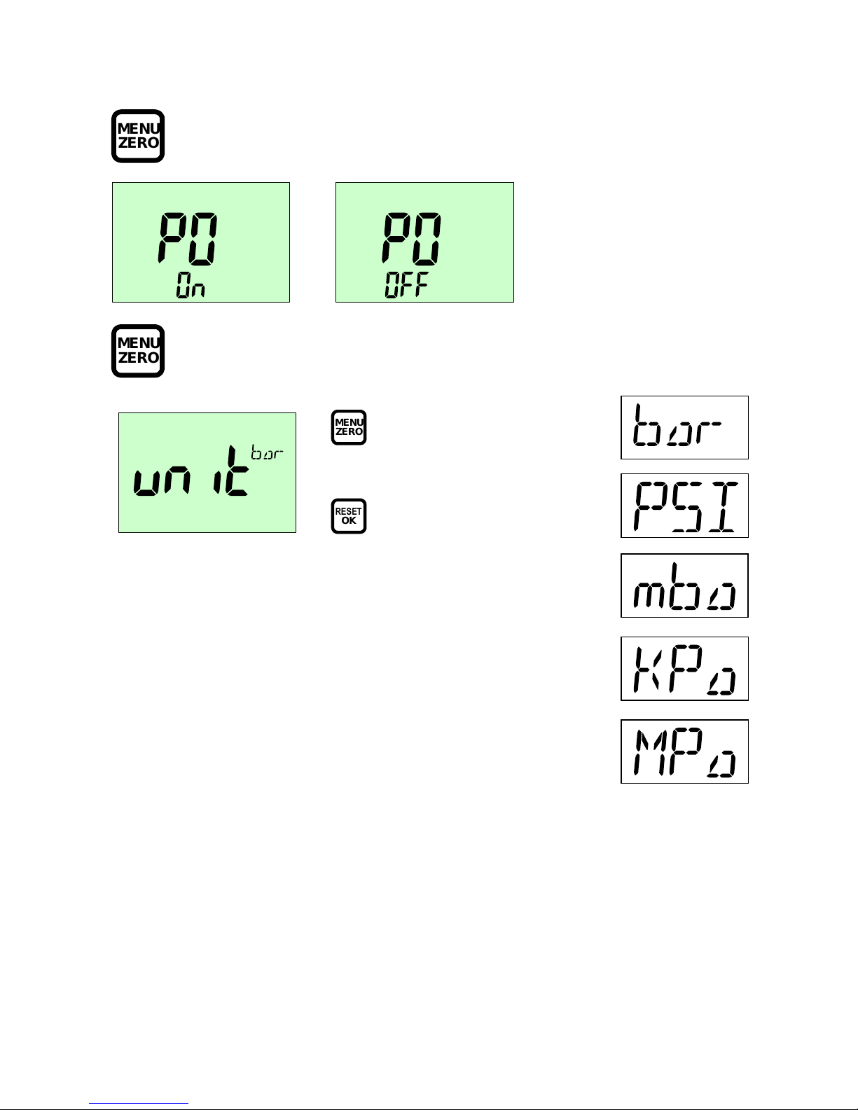
Changing the
Unit
MENUZER
O
Press for 2 s
MENUZER
O
Press to skip
MENUZER
O
Press once (briefly)
The next unit is
indicated.
RESET
O
K
Confirm unit selection
Page 15
page13of
21
5.12
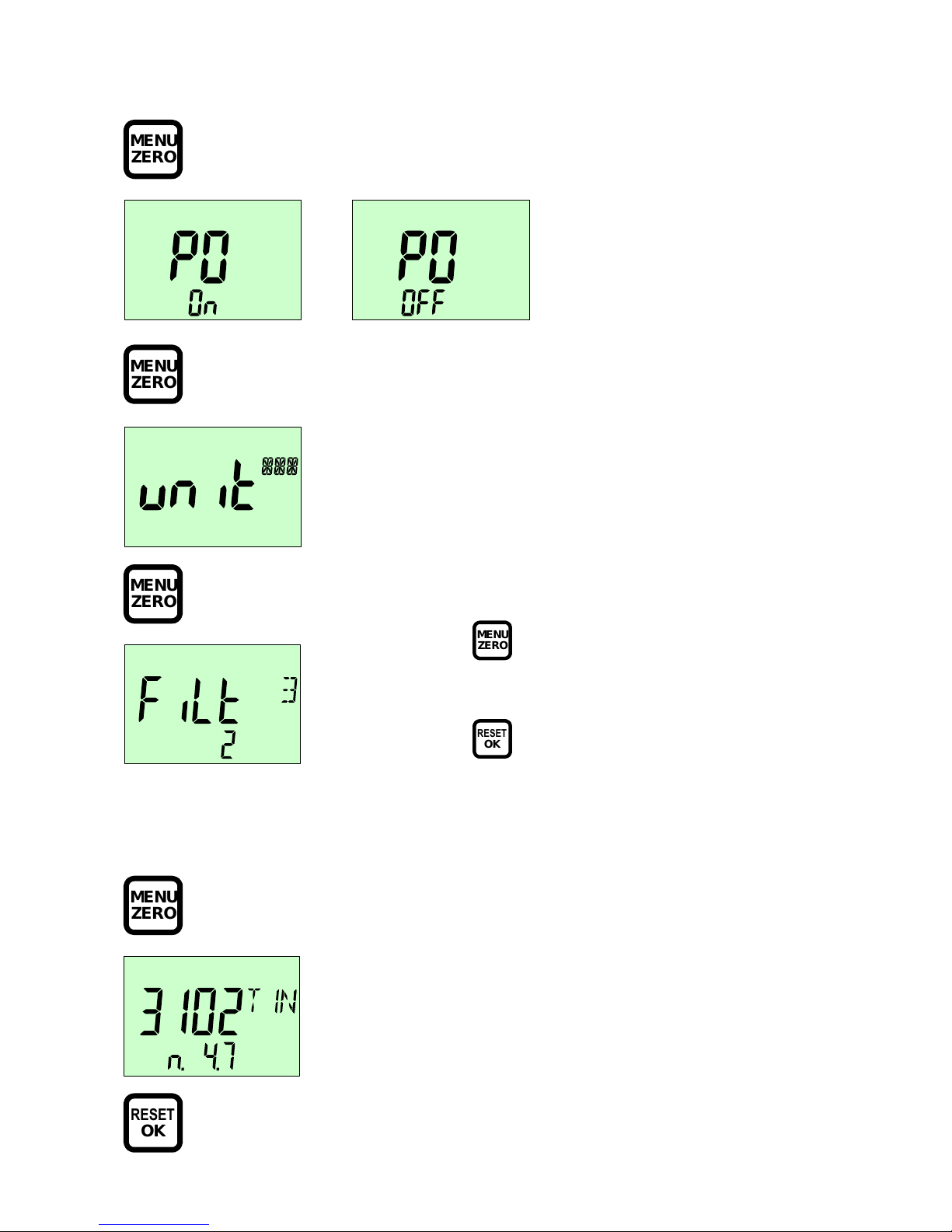
Filter Settings
MEN
U
ZER
O
P
ress 2 s
MENUZER
O
P
ress
MENUZER
O
P
ress
5.13
Display device address
In order to set up the devices manually in the PC Software „JuniorWin“ the device’s address will be
need.
MENUZER
O
P
ress
RESET
O
K
MENUZER
O
Press once (briefly)
Filter selection is indicated.
RESET
O
K
Confirm filter configuration
Display of device address (1. line)
Display of Software Version (2.line)
Page 16
page14of
21
5.14
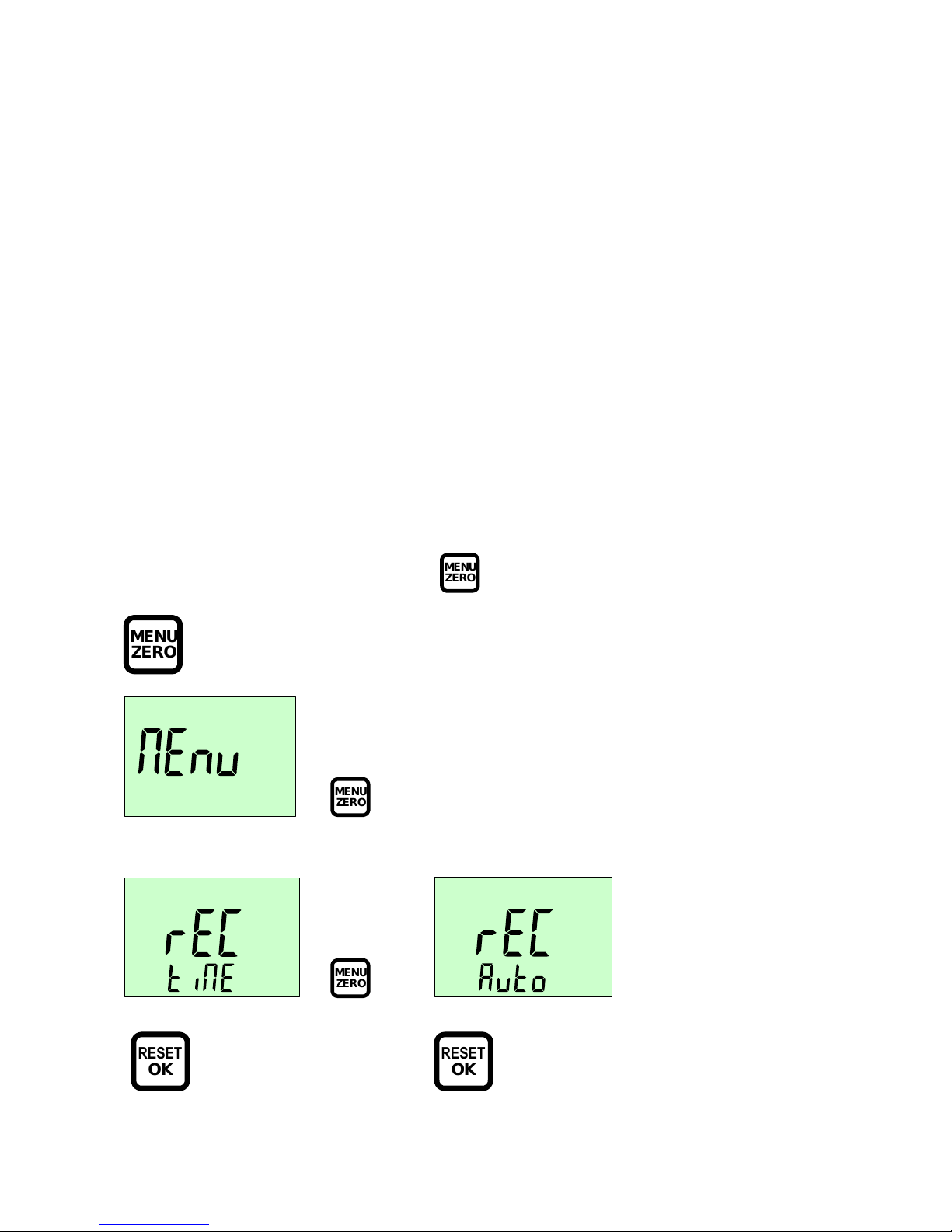
Data Memory Function
Two different data memory functions can be
used:
rEC tiME
or
rEC Auto
.
rEC tiME
time based data recording
can be started manually by
rEC MAnu
oroperated by a given trigger point
rEC tp
D
epending on the recording time the memory interval wil
l be processed automatically
(5,
000 Intervals)
.
Into each memory interval one maximum reading will be saved
.
rEC Auto
pressure peak monitoring
records
readings
above given trigger point
S
etup of individual memory interval will be done by user
.
Only readings
will be saved into data memory
which ar
e above given trigger point.
The data memory can be read out with the wireless PC Adapter and the PC Software „JuniorWin“.
The memory function will be processed with
MENUZER
O
MENUZER
O
P
ress 2 s
MENUZER
O
P
ress
MENUZER
O
RESET
O
K
RESET
O
K
rEC tiME
Function
rEC Auto
Fu
nction
will be set
will be set
Page 17
page15of
21
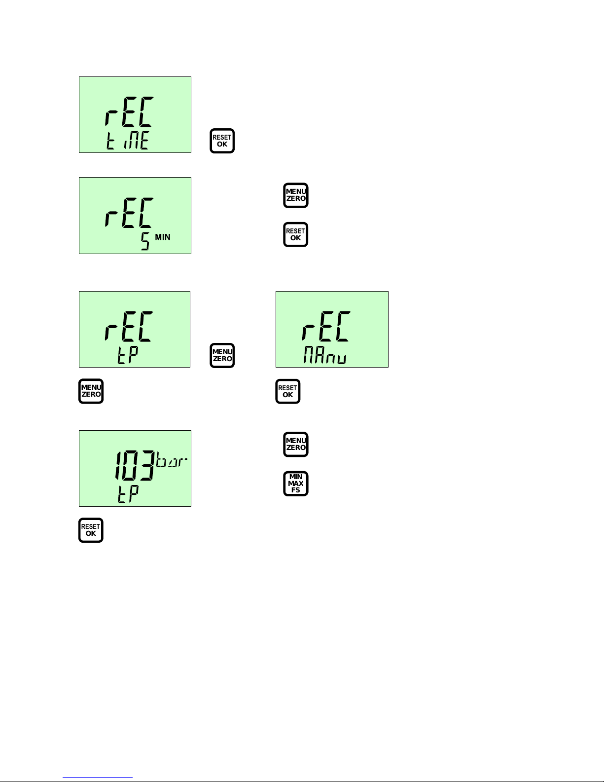
5.15
Set up
REC time
Function
RESET
O
K
confirm
Select Start with Trigger point
rEC tp
ormanually
rEC MAnu
MENUZER
O
MENUZER
O
Setup
RESET
O
K
Start data recording
0…FS (Full
Scale range
)
RESET
O
K
confirm trigger point
MENUZER
O
select upwards
MINMAXF
S
select downwards
MENUZER
O
select
3/10/30/60 min
RESET
O
K
confirm
Page 18
page16of
21
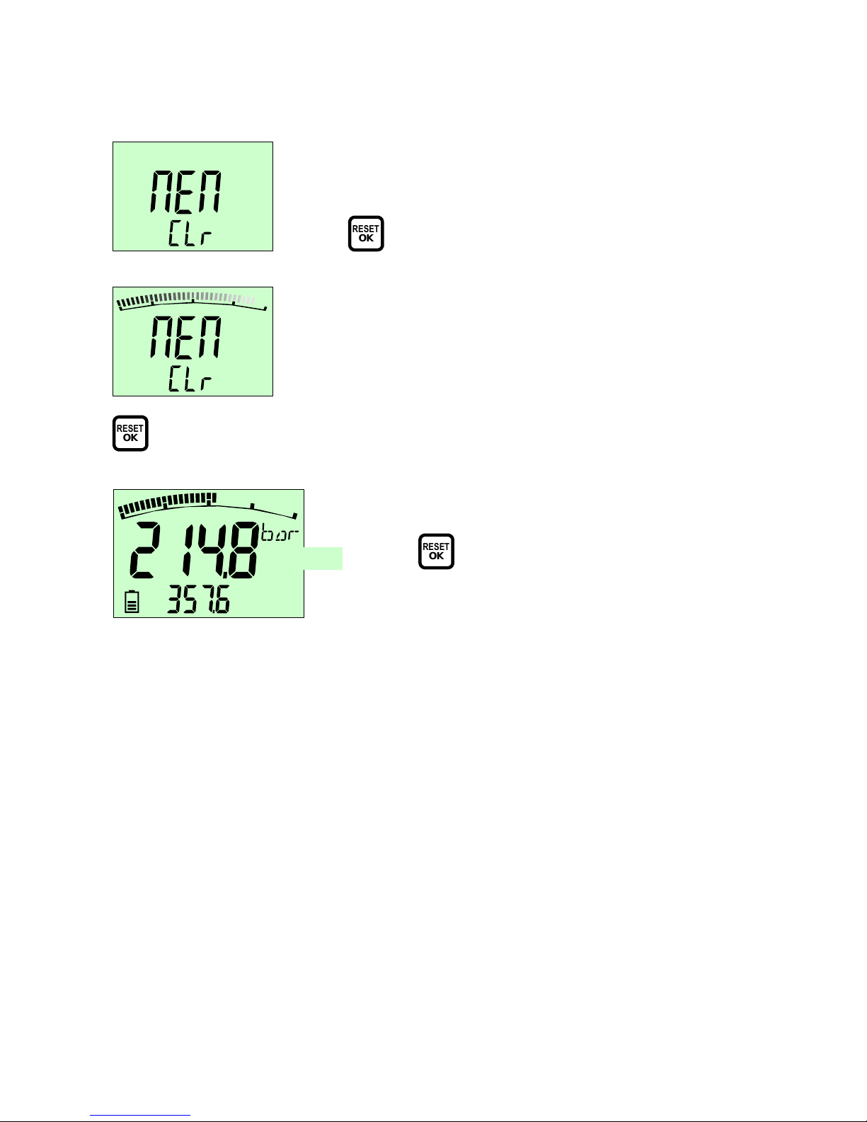
5.16
Delete D
ata M
emory
When the data memory is full it must be deleted before data recording can be started.
RESET
O
K
Delete data memory
Deleting
d
ata memory content
RESET
O
K
Start data recording
with selected trigger point (e.g. 103 bar)
MAX
REC
REC
appears in the display and flashes
RESET
O
K
cancel
data recording
REC
disappears in the display
Page 19
page17of
21
5.17
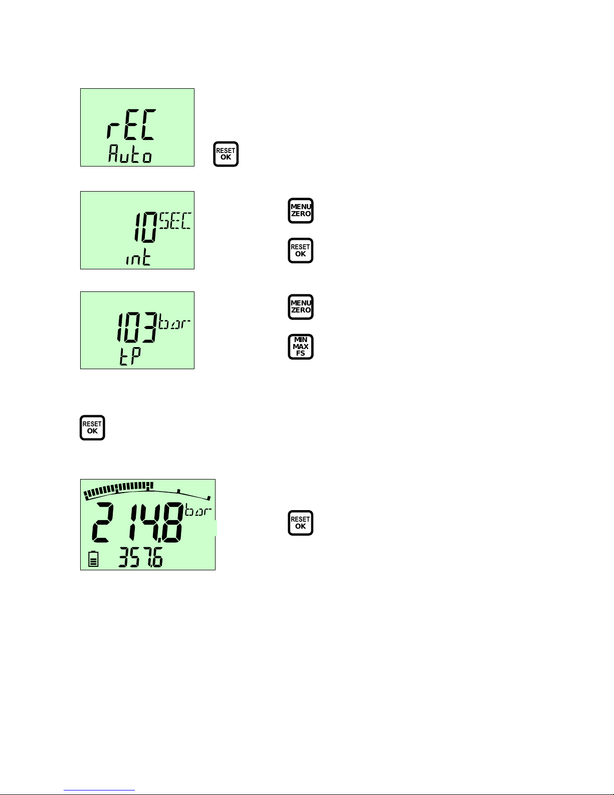
Setup Function REC
AUTO
RESET
O
K
confirm
Deleting data memory se
e
chap
t
er 5.13.
RESET
O
K
Start data recording
with selected trigger point
(e.g. 1
57.7
bar)
MAX
MENUZER
O
Select 0.1/1/10/60 s
RESET
O
K
confirm
REC
MENUZER
O
select upwards
MINMAXF
S
select downwards
REC
appears in the display and flashes
RESET
O
K
cancel data recording
REC
disappears in the display
Page 20
page18of
21
6
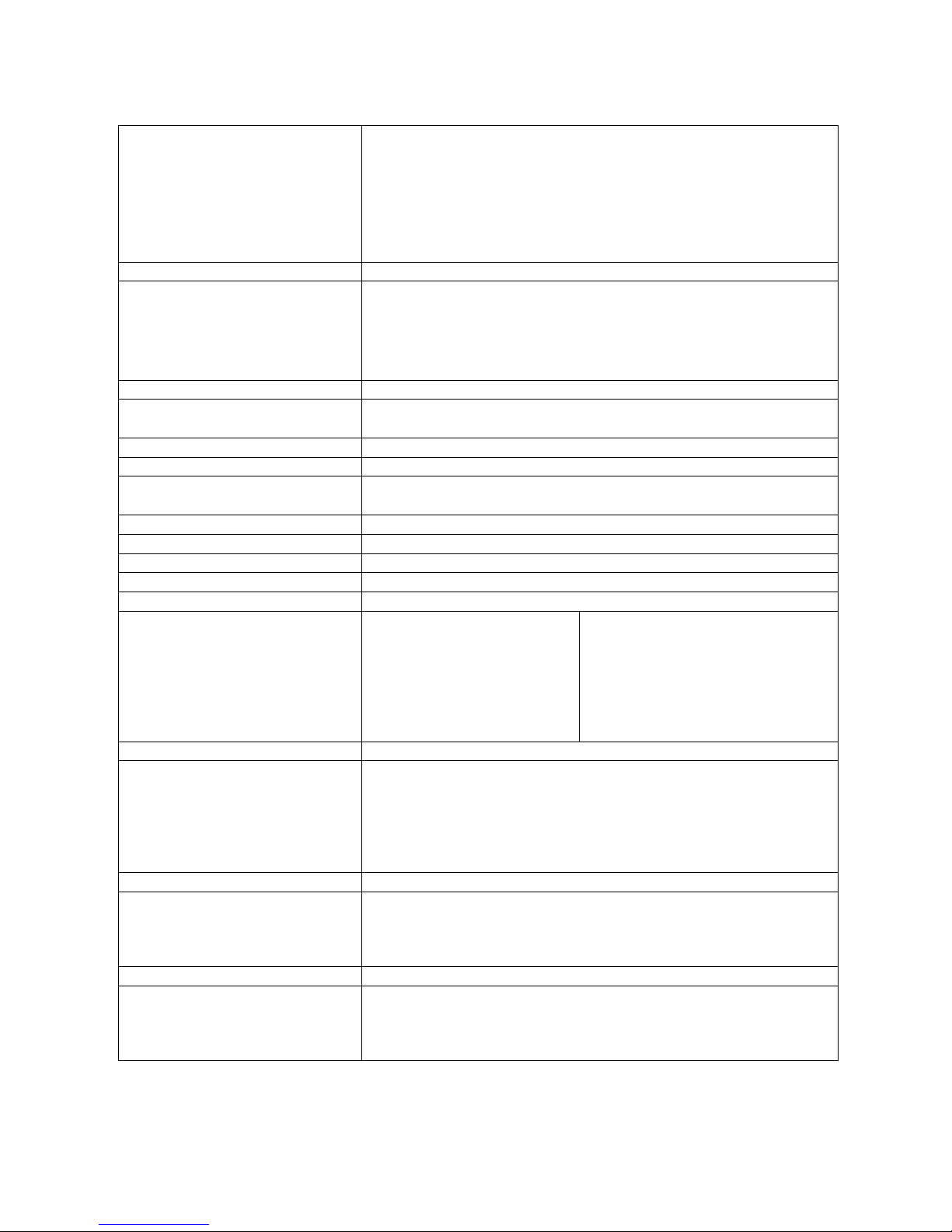
Technical Data
Version
Digital pressure gauge with
ACT
-
MIN
and
MAX Display
bar graph display (33 segments) wit
h peak and hold function
4 ½ digit LC display (15 mm) with back light illumination
Battery powered with low power electronic system
Life time cycle
8
00 h (No back light function)
Pressure port stainless steel 1.4404
¼” BSPP (ISO 1179
-
2) or 7/16
–
20 UNF (
ISO 11926
-
2/3)
Input
Ceramic Sensor cell
-
1…16 bar
Strain Gauge Cell 0…100/400/600/1,000 bar
Scan rate 10 ms
Accuracy
0.25 % FS typ.
0.5 % FS max.
Resolution 12 bit = 4,096 steps
Housing
Ø
=79mm; T = 33 mm
Zinc Die Cast with
Rubber Protection TPE
Weight (g)
540
Sealing
Standard NBR sealed
Viton
®
(FKM); EPDM on request
Parts in contact with media
Stainless Steel 1.4404, NBR, ceramics
Power
Supply
Battery 2 x 1,5 VDC AA (LR6) Alkaline (Mignon)
Ambient conditions
Ambient temperature
Storage temperature
Fluid temperature
Rel. humidity
Protection
Vibration
Shock
-
10…50 °C
-
20…+60°C
-
20…+80°C
< 85%
EN 60529 (IP
54)IEC 60068
-2-65g
IEC 60068
-2-2725g
Function
Units: bar; PSI; Mpa; kPa; mbar
MIN/MAX
-Full
Scale
Battery Status Control
Auto Power Off/On
Zero Function
Reset (Deletes MIN/MAX )
PC Funktion
PC Software "JuniorWin"
Download recorded data's
via wireless PC Interface (2,4 GHz) Range 50 m
Device Setup
Memory Function
5,000 Re
a
dings (MAX
Readings)
Setup of Memory Interval
REC TIME (Time based recording)
REC AUTO (Long Term Recording by Limit Monitoring)
Page 21
page19of
21
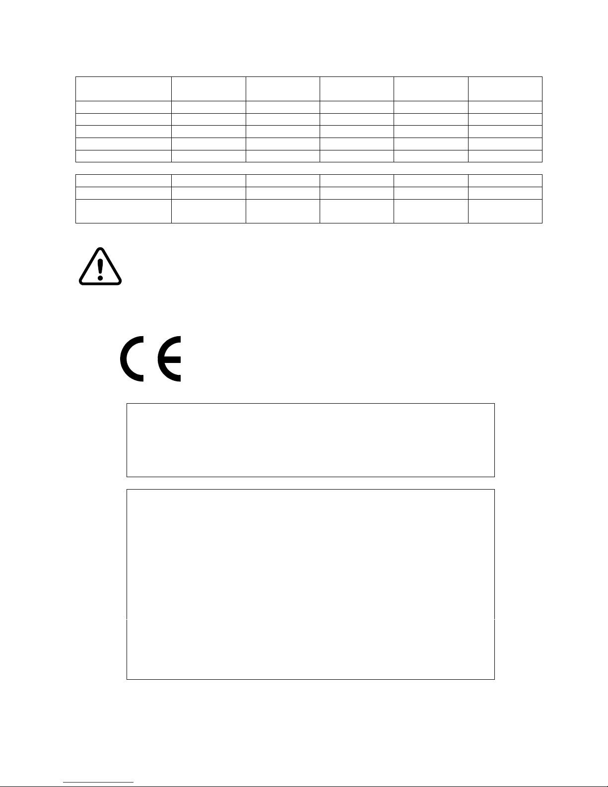
Digital Pressure Gauge ServiceJunior
wireless
Range
bar
Display
bar
Display
PSI
Display
mbar
Display
kPa
Display
MPa
-
1…16
-
1,00...
16,00
-
14,5...200,0
-
999...16000
-
100...1600
-0…100
0...100,0
0...1500
-
0...10000
0...10,00
0…400
0...400,0
0...5800
-
0...4000 (x10)
0...40,00
0…600
0...600,0
0...8700
-
0...6000 (x10)
0...60,00
0…1000
0...1000
0...15000
--0...100,0
R
ange (bar)
-
1…16
0…
100
0…400
0…600
0…1.000
Overload P
max
(bar)
40
200
800
1.200
1.500
Burst Pressure
(bar)
50
800
1.700
2.200
2.500
The
ServiceJunior
wireless
meets the guidelines of the European Community (EU).
It is confirmed that this product is appr
oved acc. to following standards:
This device complies with part 15
of t
he FC
C rules.
Op
erati
on is
subject to the
following two c
onditions:
(1) t
he de
vice may not
c
ause
harmful
interference
,
and (2) this device must accept any interf eren
ce
receiv
ed
, including
interference that may cause undesired operation.
This equipment has been tested and
found to comply with the limits for a
Class
B digital device, pursuant to part 15 of the
FCC Rules. These limits are
designed to provide reasonable
protection against harmful
interference in a
residential installation.
This equipment generates, uses and can radiate radio
frequency energy and, if not installed and used in accordance with the
instructions, may cause harmful interference
to radio communi
cations.
However, there is
no guarantee that interference will not occur
in a particular
installation. If this equipment does cause harmful interference to
radio or
television reception, which can be
determined by turning the equipment off
and
on, the user
is encouraged to try to correct
the interference by one or
more of the following measures:
-
Reorient or relocate the receiving antenna.
-
Increase the separation between the equipment and receiver.
-
Connect the equipment into an outlet on a
circuit diff
erent from that to which
the receiver is connected.
-
Consult the dealer or an experienced radio/TV technician for help.
Technical subject to change
July2009
DIN / EN 61000
-6-2DIN / EN 61000
-6-
3
Burst pressures related to tests without assembled adapters.
Exceeding the maximum ov
erload values (P
max
) may lead to
malfunctions and may even destroy the
ServiceJunior
wireless
.
 Loading...