

Page 1
Operating manual
Temperature switch
UNIT
111
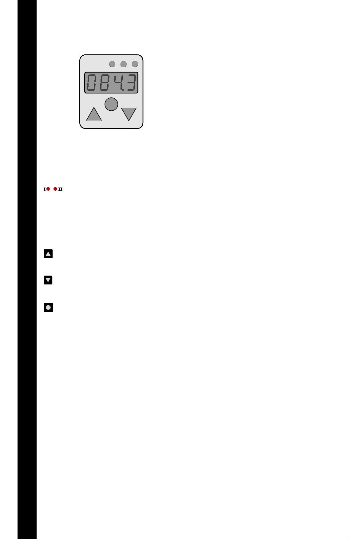
LED‘s
&&&&
4-position
digital display with
variable decimal point
Arrow key up
ENGLISHENGLISH ENGLISH
Arrow key down
Enter / OK
UNIT
Switch status indication
I = switch output 1
II = Switch output 2
(also error output)
Display of systemtemperature
in °C or °F;
display of parameters
Arrow key to look back in menu or
to set a higher parameter
Arrow key to look forward in menu
or to set a smaller parameter
value
Enter key to select a parameter
value or to confirm a parameter
value
Display of the unit
Note
The statements made in this operating manual are intended
for users with specialised knowledge.
It is essential that the user checks the statements about the
chosen product for suitability for the functions required.
Because of the various tasks and working processes in any
system, the user must check and make sure that all the
demands regarding the function and safety of the system
are satisfied by the features of the product.
Subject to alteration
Page 2
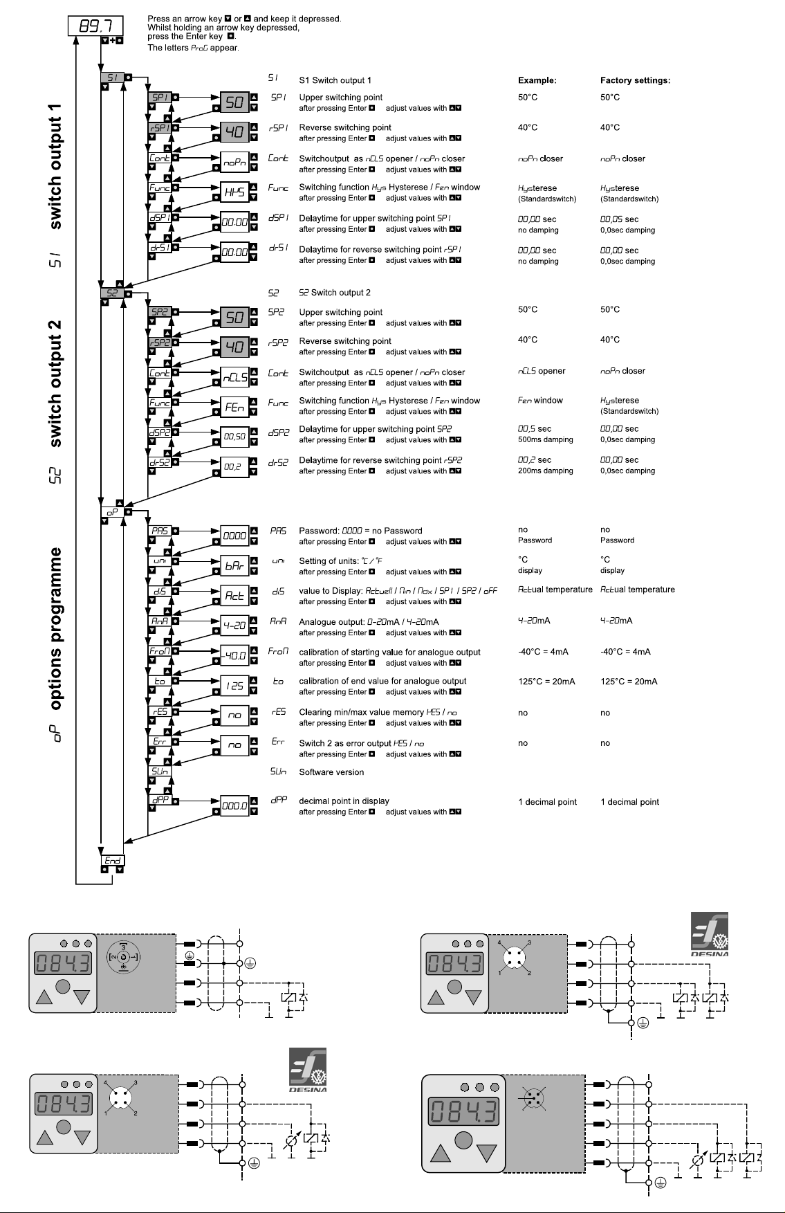
1 output; DIN43650
+Ub
S2 out
S1 out
0V/GND
+Ub
wh
bk
bn
bl
0V/GND
1
2
4
3
UNIT
III
+Ub+Ub
S1 out
S2 out
Analog
out
0V/GND
0V/GND
DESINA
bn
wh
bk
gr
bl
1
2
4
5
3
UNIT
III
43
5
21
III
UNIT
+Ub
S1 out
0V/GND
2 outputs; M12 4-pol.
1
ye
+Ub
3
bn
2
gn
0V/GND
1 output; analog output; M12 4-pol.
UNIT
III
DESINA
S1 out
Analog
0V/GND
+Ub
out
2 outputs; analog output; M12 5-pol.
1
bn
+Ub
bk
wh
bl
0V/GND
4
2
3
Page 3
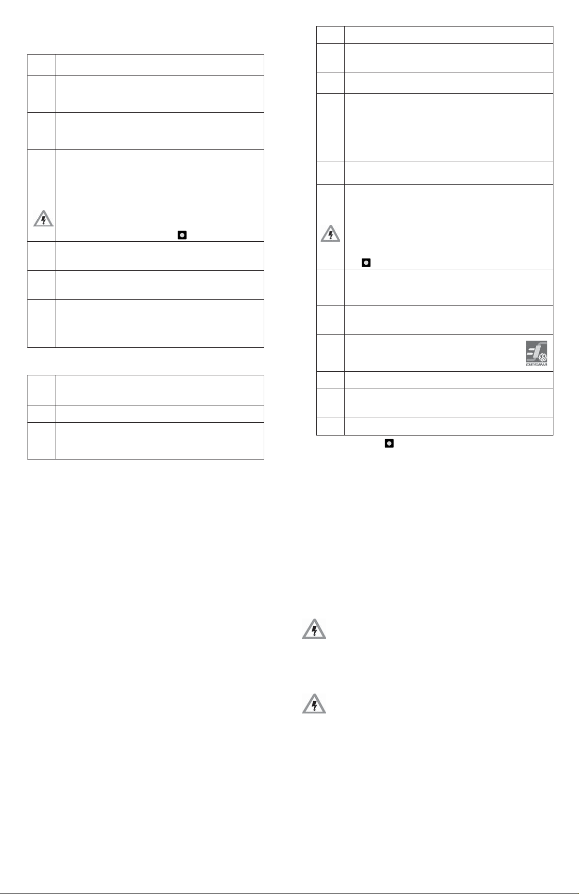
Parameters shown in digital display
Po
emmargorpsnoitpO
SAP
tupnidrowssaP
0000 drowssapon=
drowssapelpmaxE 4321 4321=
inu
:stinufognitteS
C° C°= F° F°=
Sid
yalpsidlatigidehtnonwohseblliwhcihweulaV:yalpsiD
.edomnurni
tcA erutarepmetmetsyslautcA=
niM )shguorterutarepmet(;erutarepmetmetsysmuminiM=
AM )skaeperutarepmet(;erutarepmetmetsysmumixaM=
1PS 1tniophctiwS=
2PS 2tniophctiwS=
FFO noitacidniffo=
AnA
)4tniopees(tuptuoeugolanafognitteS
02-0 Am02-0= 02-4 Am02-4=
MorF
tuptuoeugolanaehtrof)Am4ro0(eulavgnitratsfonoitarbilaC
.)4tniopees(
.C°051otC°05-morfelbatteS
rofelpmaxE AnA = 02-4 :
0000 .Am4sdleiytuptuoeugolanaehtC°0ta=
gnitratsehtfI.eulavdneehtnahtrellamssyawlasieulavgnitratsehT
eblliweulavgnitratsehtneht,eulavdneehtnahtretaergtessieulav
ehT.eulavdneehtfotahtwolebC°051fo%5tesyllacitamotua
ngisgninraw 1ttA retneehthtiwderaelcebnachcihw,raeppalliw
.ngis
ot
tuptuoeugolanaehtrof)Am02(eulavdnefonoitarbilaC
.)4tniopees(
.C°051otpuC°05-morfelbatteS
0510 .Am02sdleiytuptuoeugolanaehtC°051ta=
SEr
yromemeulavmumixamdnamuminimehtgniraelC
SEY wonyromemraelc,sey=
on yromemraelctonod,on=
rrE
)3tniopees(tuptuororrenasa2tuptuohctiwsgnimmargorP
)3tniopees(
SEY sey=
on on=
*)
Enter
Settings for options programme oP
nUS
noisreverawtfosfonoitacidnI
PPd
.tnioplamicedehtfognitteS
0000 tnioplamicedon=
0.000 tnioplamiced1=
dnE
edomgnimmargorpfodnE
2. Safety notes/ choice of product
The proper functioning in accordance with this
operating manual is guaranteed solely when the
technical specifications are adhered to.
This applies especially to keeping to the instrument nominal
pressure and also to the allowable temperature range.
Operating the selected product outside the
specification or disregard for the operating notes
can result in serious misfunctioning, and damage
to people or property due to the sinking or
dropping of suspended loads cannot be ruled out.
The temperature switch should not be exposed
continuously to the sun’s radiation
n The temperatureswitch housing and the front film
may be cleaned using a moistened cleaning cloth:
aggressive cleaning materials should never be
used.
Settings of switch outputs in menu
S1 (S1 = output 1) or S2 (S2 = output 2)
SAP
1S 1tuptuohctiwS=
1S
2S 2tuptuohctiwS=
2S
1PS
1PS )C°04.g.e(eulaverutarepmetsatupni;1tuptuohctiwS=
2PS
2PS )C°06.g.e(eulaverutarepmetsatupni;2tuptuohctiwS=
1PSr
2PSr
1PSr satupni;1tuptuohctiwsfo)1PSr(tniopgnihctiwsesreveR=
2PSr satupni;2tuptuohctiwsfo)2PSr(tniopgnihctiwsesreveR=
tnoc
nPon resolc=
SLCn renepo=
cnuF
tSYH noitcnufsiseretsyH=
nEF noitcnufwodniW=
1PSd
1PSd 1tuptuotniopgnihctiwsemityaled=
1Srd
1Srd 1tuptuotniopgnihctiwsesreveremityaled=
2PSd
2PSd 2tuptuotniopgnihctiwsemityaled=
2Srd 2tuptuotniopgnihctiwsesreveremityaled=
2Srd
eulaverutarepmet
eulaverutarepmet
satuptuohctiwS
morftupni;semityaleD 0 ot 9,99 )3tniopees(.s
)3tniopees(sutatsstisegnahctuptuohctiws
.tniopgnihctiwsehtwolebC°051fo%5.0ngisgninrawehT ttA )noitnetta(
retnEhtiwderaelcebnachcihw,raeppalliw
)3tniopees(:snoitcnufgnihctiwsfonoitceleS
edomgnimmargorpehtotniyrtnE.drowssapaotdetacidedsisihT
deretneneebevahserugiftcerrocehtnehwylnoderucesebnac
)3tniopees(:stuptuohctiwsehtgnimmargorprofuneM
)tuptuororrenasadesugniebsi2SfievitcatonsiuneM(
,erutarepmet/eulavgnitimilreppu:)PS(tniopgnihctiwS
)3tniopees(sutatsstisegnahctuptuohctiwsehthcihwta
hcihwtaerusserp/eulavgnitimilrewol:)PSr(tniopgnihctiwsesreveR
evitcepserstinahtrellamssyawlasitniopgnihctiwsesreverehT
ehtnahtrehgihtessitniopgnihctiwsesreverehtfI.tniopgnihctiws
yllacitamotuateseblliwtniopgnihctiwsesrevereht,tniopgnihctiws
Error display and precautionary hints
1ttA
stniopunemees(
PS,PSr
dna
Morf
)ot,
1rrE
3rrE
1. General instrument description
By choosing the temperature switch you have acquired a
quality product which is outstanding for its high reliability.
The following temperatures in °C or °F can be shown on the
large 4-position digital display: the actual, lowest or highest
memorized pressure and also the set switching points.
…scinortceleeugolananirorrE
.erutarepmetmetsyskcehcesaelP
.sretemarapevitcepserrehtoehtnahtrewolsieulavtesehT
pudehctamsieulavrellamseht,detavitcasi)*retnEnehW
.riaperrofdnesesaelP…evitcefedscinortceletnemurtsnI
.dedeecxeegnargnirusaem/erutarepmetlanimontnemurtsnI
.riaperroftnemurtsniehtdnesesaelp,stsisreprorrefI
The display is easily readable,thanks to the housing which
can be rotated. The self-explanatory menu-driven parameter
set-up is achieved with 3 keys. Unauthorised parameter
changes can be prevented by means of a password.
Two programmable switching outputs, each independent
of the other, and a readily programmable analogue output
are available for connection with electrical controls. Each
switching output has two switching points with which the on
and off switching temperatures can be readily set (variable
hysteresis).
The switching outputs are switched as opener or closer
corresponding to the set switching points, hysteresis or
window functions, and indicated on the status display. An
apparent function error will be signalled on the digital
display and can be further processed in accordance with
Desina. The electronics, which are protected against reverse
polarity, over-voltage and short circuits are in a fully cast
enclosure, and are thereby resistant to moisture and
vibrations.
Page 4

3. Operating modes
- 2 -
Programming mode
In the programming mode the parameters are changed
and stored thereafter continuously. An electrical supply is
not necessary for the retention of stored data (storage in
EEProm).
To ensure trouble-free operation, the temperature
switch remains internally in the run mode. If no key
has been pressed for 30 seconds, the pressure
switch changes back automatically to run mode.
Activation of the programming mode
To exclude the unintentional change of programmed
parameters, the programming mode can be activated only
by the following key combinations:
n Press an arrow key or and keep it depressed.
Whilst holding an arrow key depressed, press the
Enter key .
The letters
ProG appear.
Password protection
To prevent any unauthorised change of parameters, the
programming mode can be protected by an optional password.
n When a password has been programmed in, PAS
appears. With the arrow key
or the password is
entered and confirmed with Enter
. After this the
pressure switch can be programmed.
n If no password has been set up (password= 0000),
the pressure switch can be immediately programmes.
Programming
n Press an arrow key or to scroll through the
menu points.
n Pressing Enter shows the relevant parameters.
n Pressing the arrow keys or changes the
selected parameters. Holding the arrow key
depressed achieves fast and easy input and the
values of the parameters to be set can be changed
faster.
n· A changed value is confirmed with the Enter key
and the next menu point is then displayed.
The temperature switch carries on with its
monitoring functions to the existing parameters
until the respective change is concluded.
Reset
When the supply voltage is switched on the two arrow
keys
are pressed simultaneously.
At this point
rSt appears.
When both arrow keys and are kept depressed
and the Enter key
activated, the pressure switch resets all
the settable parameters back to the factory settings.
The temperature switch has the following operating
modes:
n Run mode (normal working operations)
n Display mode (display of set parameters such as
switching points, opener, closer...)
n Programme mode (setting of parameters such as
switching points, opener, closer...)
n Reset mode (resetting to standard values)
Switching on
When the supply voltage is switched on, the temperature
switch carries out a self-test.
n The display and the switching point indication light up.
n 150°C is displayed.
During this time (2secs.) the outputs are not active.
Run mode
After switching on, the temperature switch is in run mode.
The digital display indicates the actual system temperature
and the two yellow LED´s signal the actual switch status of
the outputs. It carries out its monitoring functions, switches
the switch outputs in accordance with the set parameters
and converts the actual system temperature into an
analogue signal.
Display mode
In the display mode the control parameters can be shown
but cannot be changed.
To ensure trouble-free operation, the temperature
switch remains internally in the run mode. If no key
has been pressed for 30 seconds, the temperature
switch changes back automatically to run mode.
Display mode activation is by the Enter key .
The letters diSP appear.
n A short touch on an arrow key or scrolls
through the menu points.
n A short touch on the Enter key shows the relevant
parameters.
D A password is shown as ----.
- 1 -
Page 5
4. Switching functions
- 4 -
5. Analogue Output
The temperature switch has two standardised output
signals from 0-20mA or 4-20mA. In addition, it is possible
to calibrate the starting and end values.
This is a prerequisite for
n compatibility with existing systems
Examples:
An output signal from 4-20 mA
for -40°C up to 125°C is required.
Resultant setting values for e.g.:
AnA = 4-20 Analogue output 4-20 mA
(see menu point AnA)
FroM = -40 -40°C = 4 mA
(see menu point FroM)
to = 125 125°C = 20 mA
(see menu point to)
6. Installation
Mechanical:
Install and de-install the temperature switch only
when there is no pressure present.
Attach the temperature switch to the appropriate process
connection. Installation should be undertaken only across
flats spanner.
Ensure that the digital display is placed in the best viewing
position by using the rotational housing adjustment.
The housing can be attached
n with self-tapping screws into two blind holes at the
back of the housing
n with clamps
A safety sleeve is required to protect the sensor against
higher pressure or aggressive mediums/substances.
Electrical:
The temperature switch may be installed only by
a qualified electrician in accordance with the
respective national and international regulations.
Protect the temperature switch from electromagnetic
influences and over-voltages.
Optional installation tips which are shown by experience to
reduce the influence of interference:
n Use shorter cables
n Avoid short distances between connecting leads and
power consuming devices and interferencegenerating electrical and electronic equipment.
n Use free running diodes
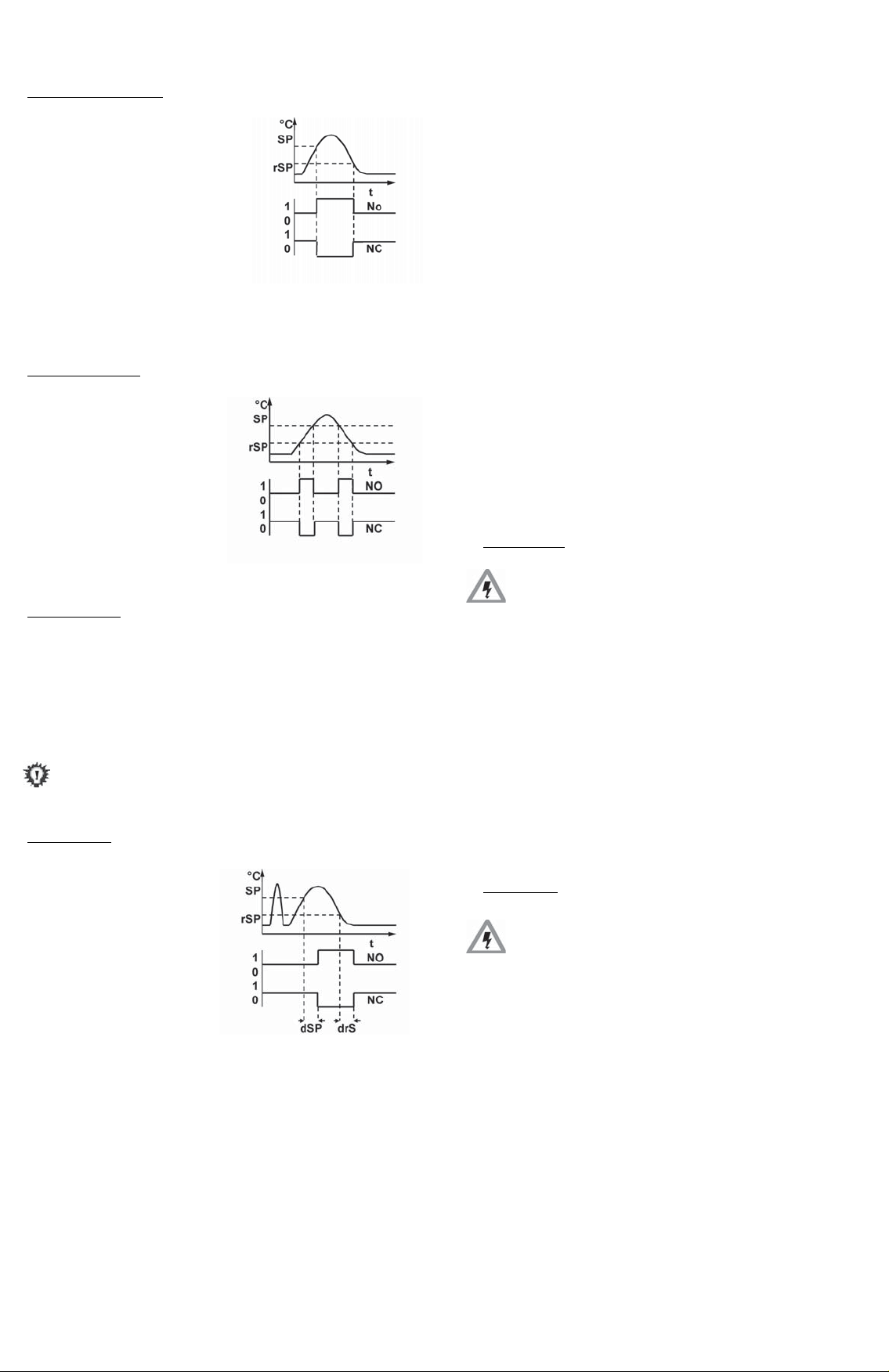
Hysteresis function:
If the system temperature
fluctuates around the nominal
value, the hysteresis keeps the
switch status of the outputs
stable. When the system
temperature is rising, the output
switches when it reaches the
respective switching point (SP); if
the pressure falls again, the
output switches back only if the
reverse switching point (rSP) is reached.
(See menu point
Window function
The window function allows
the monitoring of a defined
range.
If the system temperature
is between the switching point
(SP)and the reverse switching
point (rSP),
the output is activated.
(See menu point FunC,SP,rSP).
Error function
Switch output 2 can be used optionally as an error output
to display temperature switch function errors. As an error
output it is normally closed, and in case of errors (
Err3 ) it is open. At the same time LED II lights up. The
display and the error output remain active until the error is
cleared. (See menu point Err)
It conforms to DESINA when used with
a 4-pole M12x1 connecting plug
Delay times (0 to 99,9 secs.)
The temperature must remain
for at least this time to enable
the switch to operate. The switch
output does not immediately
change its status when it
reaches the switching event,
but only after the delay time has
elapsed. If the switching event
no longer pertains when the
delay time has elapsed, the
switch output does not change.
(See menu points
FunC, SP,rSP)
Err1 ,
dSP and drS)
- 3 -
Page 6
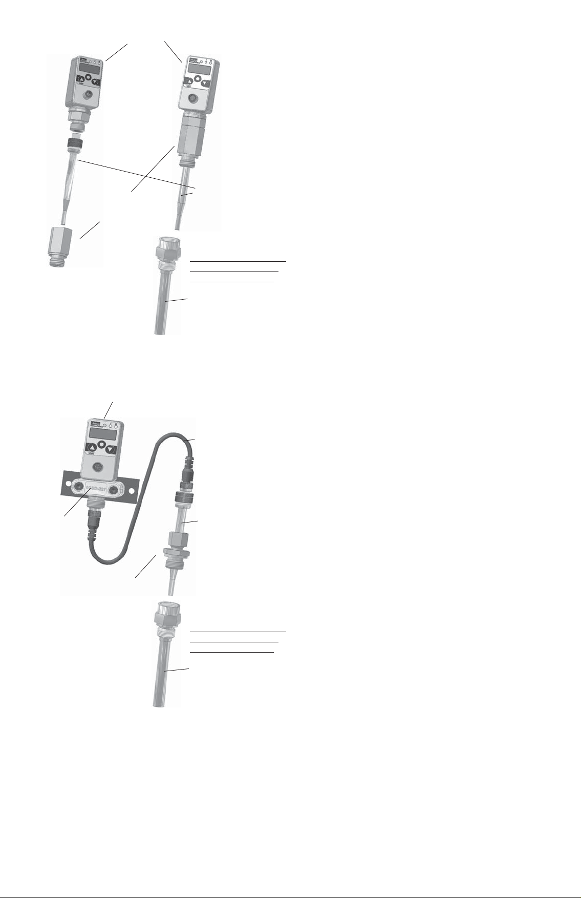
TemperatureController
Connection adapter
SCA-TT-10-SD
SCTSD
Temperature sensor
SCTT-10-XXX-07
In addition against higher
pressure or aggressive
substances/mediums
Safety sleeve
SCA-TT-10-XXX
TemperatureController
Tube clamp
SCSD-S27
BSPP Fitting
SCA-TT-10-1/2
SCTSD
Cable
SCK-410-03-45-45
Temperature sensor
SCTT-10-XXX-07
In addition against higher
pressure or aggressive
substances/mediums
Safety sleeve
SCA-TT-10-XXX
 Loading...