

Page 1

User manual
Refrigeration Dryer
PRD125
PRD150
PRD175
DATE:2012.06.20 -Rev.2
CODE:272896
Page 2

Page 3

1
SPL040 ---060 (60Hz)
English
Index
1. Safety
2. Introduction
3. Installation
4. Commissioning
5. Control
6. Maintenance
7. Troubleshooting
8. Appendix
, There are symbols whose meaning is
given in the paragraph 8.1.
8.1 Legend
8.2 Installation diagram
8.3 Technical data
8.4 Spare parts list
8.5 Exploded drawings
8.6 Dimensional drawings
8.7 Refrigerant circuits
8.8 Wiring diagram
1 Safety
1.1 Importance of the manual
S Keep it for the entire life of the machine.
S Read it before any operation.
S It is subject to changes: for updated information see the ver-
sion on the unit.
1.2 Warning signals
!
Instruction for avoiding danger to persons.
Y
Instruction for avoiding damage to the equipment.
Z
The presence of a skilled or authorized technician is required.
,
There are symb ols whose meaning is given in the para.8.
1.3 Safety instructions
! Always disconnect the appliance from the main power sup-
ply before starting maintenance work.
! The manual is intended for the end---user, only for opera-
tions performable with closed panels: operations requiring opening with tools must be carried out by skilled and qualified personnel.
Y Do not exceed the design limits given on the dataplate.
! Y It is the user’s responsibility to avoid loads different
from the internal static pressure. The unit must be appropriately
protected whenever risks of seismic phenomena exist.
!The safety devices on the compressedair circuit must be pro-
vided for by the user.
Only use the unit for professional work and for its intended pur-
pose.
The user is responsible for analysing the application aspects for
product installation, and following all the applicable industrial
and safety standards and regulations contained in the product
instruction manual or other documentation supplied with the
unit.
Tampering or replacement of any parts by unauthorisedpersonnel and/or improper machine use exonerate the manufacturer
from all responsibility and invalidate the warranty.
The manufacturer declines and present or future liability for
damage to persons, things and the machine, due to negligence of
the operators, non ---compliance with all the instructions given in
this manual, and non---application of current regulations regarding safety of the system.
The manufacturer declines any liability for damage due to alterations and/or changes to the packing.
It is the responsibility of the user to ensure that the specifications
provided for the selection of the unit or components and/or
options are fully comprehensive for the correct or foreseeable
use of the machine itself or its components.
! IMPORTANT: The manufacturer reserves the right to mo-
dify this manual at any time.
For the most comprehensive and updated information, the user
is advised to consult the manual supplied with the unit.
1.4 Residual risks:
The installation, start up, stopping and maintenance of the ma-
chine must be performed in accordance with the information and
instructions given in the technical documentation supplied and
always in such a way to avoid the creation of a hazardous situation. The risks that it has not been possible to eliminate in the
design stage are listed in the following table.
part
affected
residual
risk
manner of
exposure
precautions
heat exchanger
coil
small cuts contact
avoid contact, wear
protective gloves
fan grille and
fan
lesions
insertion of pointed objects through
the grille while the
fan is in operation
do not poke objects
of any type through
the fan grille or
place any objects
on the grille
inside the unit:
compressor and
discharge pipe
burns contact
avoid contact, wear
protective gloves
inside the unit:
metal parts and
electrical wires
intoxication,
electrical
shock, serious
burns
defects in the insulation of the p ower
supply lines upstream of the electrical panel; live
metal parts
adequate electrical
protection of the
power supply line;
ensure metal parts
are properly connected to earth
outside the unit:
area surrounding the unit
intoxication,
serious burns
fire due to sho rt
circuit or overheating of the supp ly
line upstream of
the unit’s electrical
panel
ensure conductor
cross---sectional
areas and the supply line protection
system conform to
applicable regulations
2 Introduction
This manual refers to refrigeration dryers designed to guarantee
high quality in the treatment of compressed air.
2.1 Transport
The packed unit must:
a) remain upright;
b) be protected against atmospheric agents;
c) be protected against impacts.
2.2 Handling
Use a fork ---lift truck suitable for the weight to be lifted, avoiding
any type of impact.
Always disconnect the dryer from the main power sup-
Page 4
SPL040 ---060 (60Hz)
2
English
2.3 Inspection
a) All units are assembled, wired, filled with coolant and oil, and
tested under standard operating conditions in the factory;
b) on receiving the machine check its condition: immediately
notify the transport company in case of any damage;
c) unpack the unit as close as possible to the place of installa-
tion.
2.4 Storage
If several units have to stacked, follow the notes given on the
packing. Keep the unit packed in a clean place protected from
damp and bad weather.
3 Installation
3.1 Procedures
Install the dryer inside, in a clean area protected from direct atmospheric agents (including sunlight).
Y Correctly connect the dryer to the compressed air inlet/out-
let connections.
Y For correct installation, follow the instructions given in par.
8.2 and 8.3.
All dryers must be fitted with adequate pre---filtration near the
dryer air inlet.Seller is excluded any obbligation of compensation
or refund for any direct or indirect damage caused by its absence.
Y Pre---filter element (for 3 micron filtration or better) must
be replaced at least once a year, or sooner as per manufacturer
recommendations.
3.2 Operating space
YLeave adequateclearancearoundthedrier for maintenance
operations.
On the condenser side, leave at least 3.94 inches (10 cm) clearance to ensure correct air flow.
3.3 Tips
To prevent damage to the internal parts of the dryer and air compressor, avoid installations where the surrounding air contains
solid and/or gaseous pollutants (e.g. sulphur, ammonia, chlorine
and installations in marine environments).
Theductingof extractedair is not recommendedfor versions with
axial fans.
3.4 Electrical connection
Use approved cable in conformity with the local laws and regulations (for minimum cable section, see par. 8.3).
Install a differential thermal magnetic circuit breaker with
contact opening distance ² 0.12 inches (3 mm) ahead of the system (IDn = 0.3A) (see the relevant current local regulations).
The nominal current In of the magnetic circuit breaker must be
equal to the FLA with an intervention curve type D.
3.5 Condensate drain connection
The dryer is supplied either with a float drain, a timed drain or an
electronic level sensing drain.
If a timed or electronic unloader is installed, use terminals CN
(R1---S1) (see par. 8.8).
For timed and electronic drains: refer to separate manual suppliedwiththedryerforspecific detailsconcerningthecondensate
drain.
Y Make the connection to the draining system, avoiding con-
nection in a closed circuit shared by other pressurized discharge
lines. Check the correct flow of condensate discharges. Dispose
of all the condensate in conformity with current local environmental regulations.
4 Commissioning
4.1 Preliminary checks
Before commissioning the dryer, make sure:
a) installationwas carried out according that givenin the section
3;
b) the air inlet valves are closed and that there is no air flow
through the dryer;
c) the power supply is correct;
4.2 Starting
a) Start the dryer before the air compressor by means of the
main power switch (QS); the power lamp will illuminate
(green);
b) after at least 5 minutes slowly open the air inlet valve and
subsequently open the air outlet valve: the dryer is now
performing its air drying function.
4.3 Operation
a) Leave the dryer on during the entire period the air compres-
sor is working;
b) the dryer operates in automatic mode,thereforefieldsettings
are not required;
c) in the event of unforeseen excess air flows, by---pass to avoid
overloading the dryer;
4.4 Stop
a) Stop the dryer 2 minutes after the air compressor stops or in
any case after interruption of the air flow;
b) do not allow compressed air to flow through the dryer when
the latter is not running;
c) switch off at the main power switch (QS). The power light
goes out and the compressor stops.
5 Control
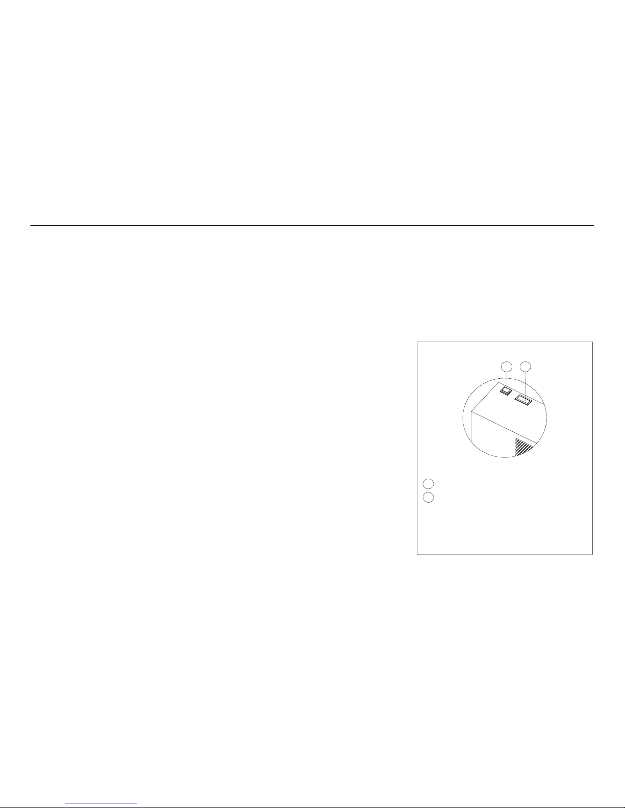
Main power switch
Dewpoint indicator
The dewpoint indicator can show one of three conditions:
blue: dewpoint too low
green: dewpoint ideal
red: dewpoint too high
11
QS
QS
11
Page 5

3
SPL040 ---060 (60Hz)
English
6 Maintenance
a) The machine is designed and built to guarantee continuous
operation;however, the life of its componentsdepends on the
maintenance performed;
b) when requesting assistance or spare parts, identify the ma-
chine (model and serial number) by reading the dataplate located on the unit.
6.1 General instructions
! Before any maintenance, make sure:
S the pneumatic circuit is no longer pressurized;
S the dryer is disconnected from the main power supply.
Y Always use the Manufacturer’s original spare parts: other-
wise the Manufacturer is relieved of all liability regarding machine malfunctioning.
Y In case of refrigerant leakage, contact qualified and author-
ized personnel.
Y The Schrader valve must only be used in case of machine
malfunction:otherwise any damage caused by incorrect refrigerant charging will not be covered by the warranty.
6.2 Refrigerant
Z
Charging: any damage caused by incorrect refrigerant replacement carried out by unauthorized personnel will not be covered
by the warranty.
Y At normal temperature and pressure, the R134a refrigerant
is a colourless gas classified in SAFETY GROUP A1 --- EN378
(group 2 fluid according to Directive PED 97/23/EC);
GWP (Global Warming Potential) = 1300.
! In case of refrigerant leakage, ventilate the room.
6.3 Preventive Maintenance Programme
To guarantee lasting maximum dryer efficiency and reliability:
Maintenance
Activity Description
Maintenance Interval
(standard operating conditions)
Activity
Daily
Weekly
4 Months
12 Months
Check POWER ON indicator is lit.
Check control panel indicators.
Check condensate drain.
Clean condenser fins.
Check electrical absorption.
Depressurize the dryer.
Complete drain maintenance.
Depressurize the dryer.
Repalce pre--- and post ---filter elements.
check service
The following are available (see par. 8.4):
a) service kits
1. compressor kits;
2. fan kits;
3. automatic expansion valve kits;
4. hot gas valve kits;
b) individual spare parts.
6.4 Dismantling
Z
The refrigerant and the lubricating oil contained in the circuit
must be recovered in conformity with current local environmental regulations.
Recycling
Disposal
structural work steel/epoxy---polyester resins
exchanger aluminium
pipes aluminium/copper
drain polyamide
exchanger insulation EPS (sintered polystyrene)
pipe insulation synthetic rubber
compressor steel/copper/aluminium/oil
condenser steel/copper/aluminium
refrigerant R134a
valves brass
electrical cables copper/PVC
Page 6

SPL040 ---060 (60Hz)
4
English
7 Troubleshooting Z
Condenser dirty
Ambient temperature
over 1 22˚F (50˚C)
Compressor
components
perished
Repair or
replace
compressor
Z
Seek external
assistance
Compressor
winding insulation
partially perished
(compressor
too hot)
Heat exchanger
fouled with
debris
Reduce compressed
air quantity or air
temperature
Compressor
noisy
Excessive
current
consumption
High pressure
drop on air side
High refrigerant
discharge
pressure:
HT trip.
Fan pressure/
thermostat
switch (PV)
calibration error
or damaged.
Condenser
dirty
Ice formation
on evaporator
(low
evaporation
pressure)
Clean heat
exchanger (blow
compressed air in
opposite direc-
tion to operating
air flow). Fit/
renew prefilter
By---pass air flow
keeping air inlet
open. Open con-
densate drain
valve manually.
Restart, checking
the calibration of
the expansion
valve or hot gas
valve.
Z
High dew
point
High refrigerant
temperature.
HT trip.
Fan does not work
Excessive thermal load
(compressor head too hot)
Low current consumption
Clean
condenser
Reduce
temperature
Replace fan
Z
Insufficient
refrigerant: repair any
leaks and recharge the
circuit
Z
Clean
condenser
Fan does
not work
Replace fan
Z
Replace
pressure switch
Z
Condenser
dirty
Clean
condenser
Fan does
not work
Replace fan
Z
FAULT
CAUSE REMEDY
No
No
No
No
No
No
No
No
No
No
No
No
No
Yes
Yes
Yes
Yes
Yes
Yes
Yes
Yes
Yes
Yes
Yes
Yes
Yes
Yes
Page 7

5
8 Appendix
8.1 Legend
Meaning
Meaning
ķMC
Compressor
ԤHT
High temperature safety thermostat
ĸ
Refrigerant condenser
ԥ
Expansion capillary
ĹEV1-2
Fan motor
ԦHP
High pressure switch
ĺ
Evaporator
CN
Electronic condensate drain power supply
Ļ
Separator
SK
Overload protector
ļ
Power cable
KA
Starting relay
ĽAEV
Expansion automatic valve
C/Cs
Compressor starting capacitor
ľ
Refrigerant filter
QF
Residual---current automatic circuit breaker
Ŀ HGV
Hot gas valve
QS
Main power switch
ŀ
Air---air exchanger
Cr
Compressor run capacitor
Ԣ
Dewpoint indicator
HL
Power light
ԣPV
Fan pressure switch
A
Cover
Page 8

6
8.2 Installation diagram
1
5
A
4
8 8 8
2
3
6
B
7
8 8
Safety valves for not exceeding dryer design pressure
Hoses for air connections if the system undergoes vibrations
Suitable dampers if the system undergoes pulsations
1 Air compressor
2 Dryer
3 By---pass unit
4 Filter (3 micron filtration or better) near dryer air inlet
5 Tank in position A or in B
6 Outlet filter
7 Oil---Water separator
8 Condensate drain
Page 9

15
SPL040 ---060 (60Hz)
8.3 Technical data / Caractéristiques techniques / Datos técnicos
Weight Refrigerant
MIN.---MAX.
Ambient temperature
Minimum
Compressed
air inlet/outlet
Amb
Compressed
air inlet
Air---side
max. working
F.L.A. [A]
Minimum
section
validated cable
Sound pressure
level
R
134a (Kg)
During transport
and stockage
After
installation
temperature
pressure
for eletrical
connection
level
(lb) (kg)
(oz) (kg)
In
Max
115V±10%
1ph/60Hz
230V±10%
1ph/60Hz
Ø NPT
[dB(A)]
SPL040
115 52 19.4 0.55 13.44 7.3
SPL050
128 58 29.6 0.84
32---122 ˚F
0---50˚C
41---122 ˚F
5---50˚C
149˚F
65˚C
232 PSIg
16 bar
15.35 8.41
3G
AWG
1
6
NPT
(compatible)
1”1/2
55
SPL060
132 60 31.7 0.90
050C550C65C16ba
r
--- 8.34
1611/
2
Calibration values Expansion automatic valve Hot gas valve Fan pressure switch
High temperature
safety thermostat
High pressure switch
7 AEV 9 HGV 12 PV 13 H T 15 HP
SPL040
32 PSIg
2.2 barg
---
ON: 160 PSIg
OFF: 116 PSIg
185˚F
85˚C
---
SPL050---060
---
32 PSIg
2.2 barg
g
ON: 11 bar
OFF: 8 bar
266˚F
130˚C
406 PSIg
28 bar
7
PRD125
PRD175
PRD150
PRD125
PRD150--175
Page 10
8
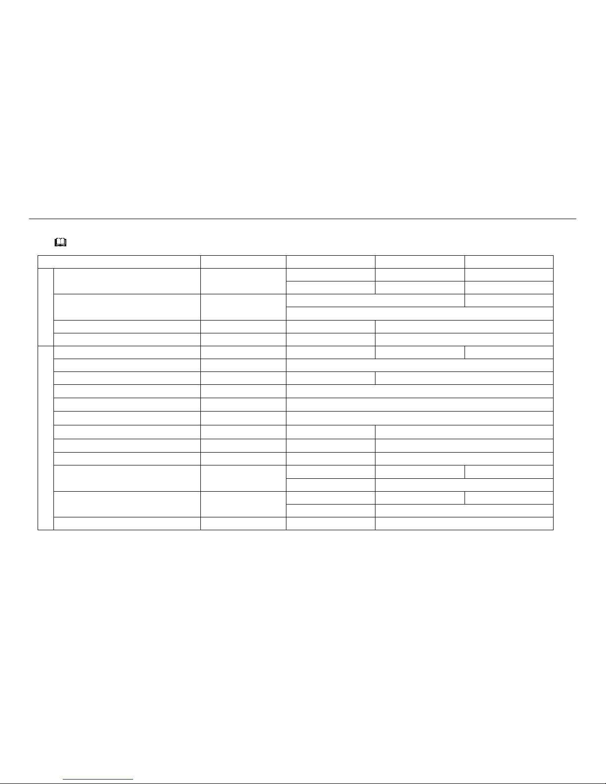
8.4 Spare parts list
(See paragraph 8.5)
PRD125 PRD150 PRD175
a)
Compressor kit
(115V/1Ph/60Hz)
① ⑧
SP-147341 SP-147738
——
(230V/1Ph/60Hz)
SP-147398 SP-147737 SP-147740
Fan kit
(115V/1Ph/60Hz)
③
SP-381616
——
(230V/1Ph/60Hz)
SP-381794
Automatic expansion valve kit
⑦ ⑧
SP-473109
——
Hot gas valve kit
⑧ ⑨
——
SP-474433
b)
Refrigerant condenser
②
SP-114808 SP-114809 SP-114810
Evaporator/Separetor/Air-air heat-exchanger
④ ⑤ ⑩
SP-472143
Power cable
⑥
SP-256347
——
Refrigerant filter
⑧
SP-206218
Dewpoint indicator
⑪
SP-354317
Fan pressure switch
⑫
SP-354110CX
High temperature safety thermostat
⑬
SP-473399 SP-474434
High pressure switch
⑮
——
SP-354160
Main power switch
QS
SP-255132 SP-255042
Power light
(115V/1Ph/60Hz)
HL
——
SP-271011
——
(230V/1Ph/60Hz)
——
SP-255229
Compressor relay
(115V/1Ph/60Hz)
KM
——
SP-255943
——
(230V/1Ph/60Hz)
——
SP-255944
Cover
A
SP-139151 SP-139152
Page 11
17
SPL040 ---060 (60Hz)
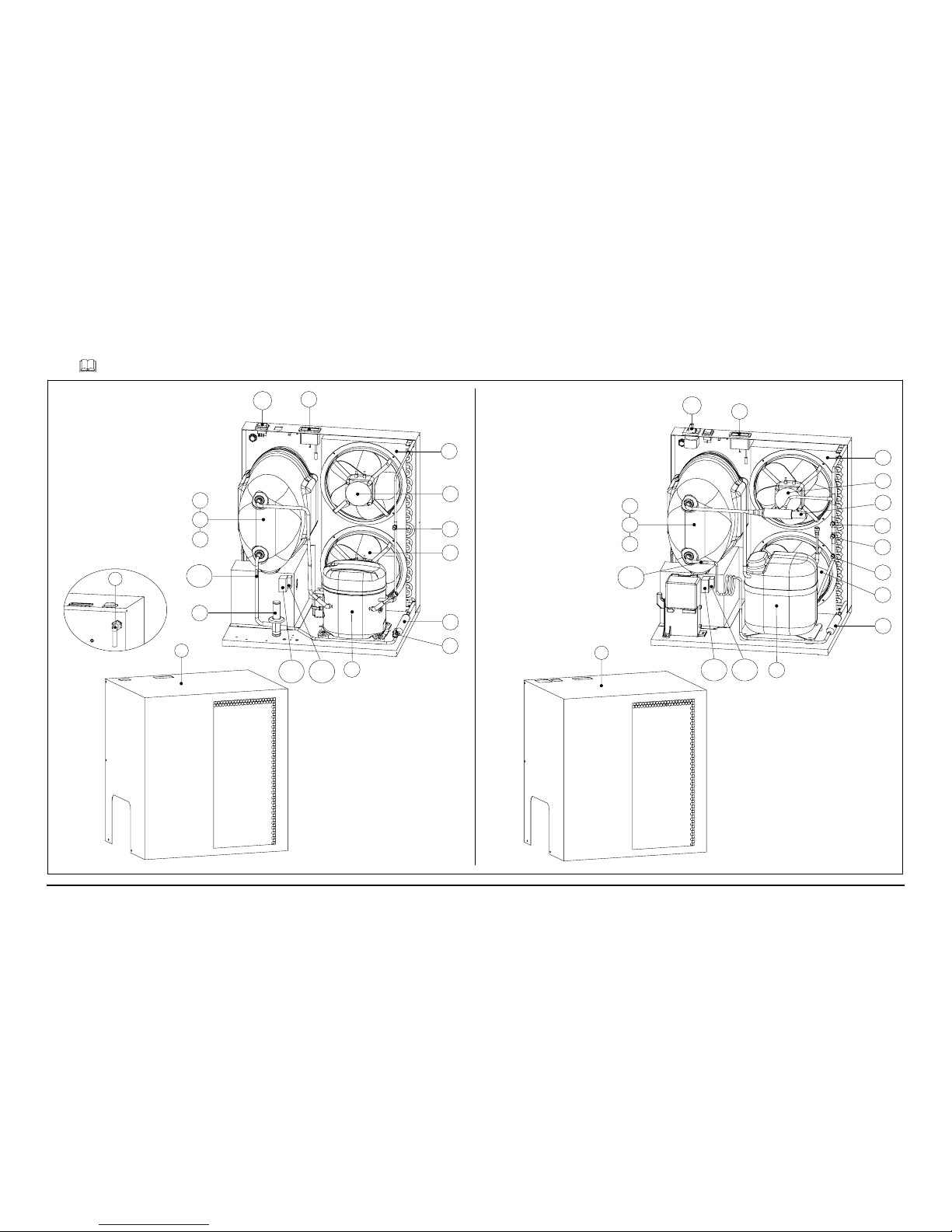
8.5 Exploded drawing / Vues éclatées / Dibujos de vista despiezada
6
A
SPL040
SPL050--060
A
11
2
3
3
12
8
13
5
4
10
7
QS
1
KA1 KT
T01
11
QS
2
3
3
12
8
1
15
9
5
4
10
13
KA1 KT
T01
PRD125
PRD150--175
9
Page 12
SPL040 ---060 (60Hz)
18
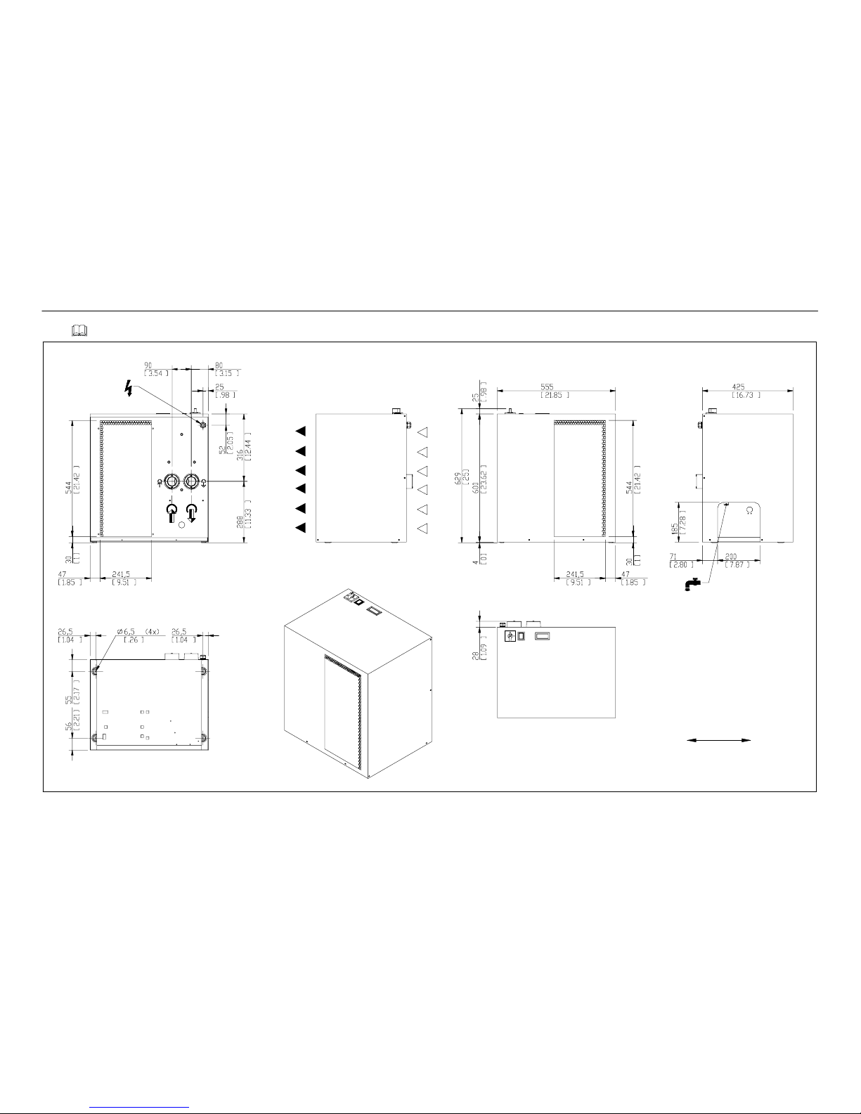
8.6 Dimensional drawing / Cotes / Dibujos de dimensiones
[ inches ]
mm
10
Page 13

19
SPL040 ---060 (60Hz)
8.7 Refrigerant circuit / Circuits de fluide frigorigène / Circuitos de refrigerante
SPL040 SPL050--060
11
PRD125
PRD150--175
Page 14

SPL040 ---060 (60Hz)
20
8.8 Wiring diagram / Schéma électrique / Esquema eléctrico SPL040
12
PRD125
Page 15
21
SPL040 ---060 (60Hz)
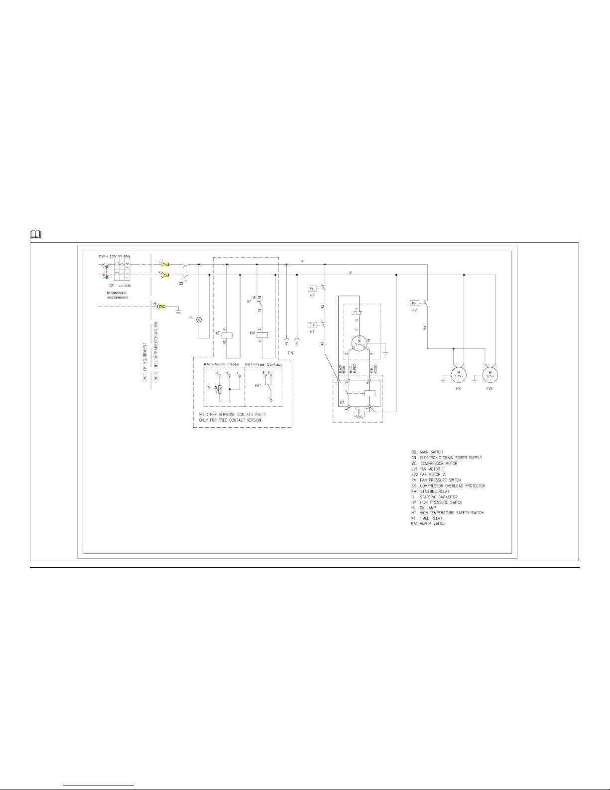
Wiring diagram / Schéma électrique / Esquema eléctrico SPL050
PRD150
13
Page 16

SPL040 ---060 (60Hz)
22
Wiring diagram / Schéma électrique / Esquema eléctrico SPL060
PRD175
14
Page 17

Page 18

Parker Hannifin Corporation
Finite Airtek Filtration Division
4087 Walden Avenue
Lancaster, NY 14086
phone 716 686 6400
www.parker.com/faf
c 2012 Parker Hannifin Corporation. Product names are trademarks
or registered trademarks of their respective companies
 Loading...