

Page 1
Bulletin HY11-3236-M1/UK
Electronic for
Proportional Pressure/
Throttle Valves
Installation Manual
Series PCD 00A-400
Design ³ 19
Parker Hannifin
Manufacturing Germany GmbH & Co. KG
Hydraulic Controls Division Europe
Gutenbergstr. 38
41564 Kaarst, Germany
Tel.: (+49) 181 99 44 43 0
E-mail: [email protected]
Copyright © 2016, Parker Hannifin Corp.
Page 2

2
PCD00A_19 3236-M1 UK.indd CM 10.02.16
Electronic Prop. Pressure/Throttle Valves
Series PCD 00A-400
Installation Manual
Parker Hannifin Corporation
Hydraulics Group
Offer of Sale
Please contact your Parker representation for a detailed ”Offer of Sale”.
FAILURE OR IMPROPER SELECTION OR IMPROPER USE OF THE PRODUCTS DESCRIBED
HEREIN OR RELATED ITEMS CAN CAUSE DEATH, PERSONAL INJURY AND PROPERTY
DAMAGE.
This document and other information from Parker-Hannifin Corporation, its subsidiaries and
authorized distributors provide product or system options for further investigation by users having
technical expertise.
The user, through its own analysis and testing, is solely responsible for making the final selection
of the system and components and assuring that all performance, endurance, maintenance,
safety and warning requirements of the application are met. The user must analyze all aspects
of the application, follow applicable industry standards, and follow the information concerning
the product in the current product catalog and in any other materials provided from Parker or its
subsidiaries or authorized distributors.
To the extent that Parker or its subsidiaries or authorized distributors provide component or
system options based upon data or specifications provided by the user, the user is responsible for
determining that such data and specifications are suitable and sufficient for all applications and
reasonably foreseeable uses of the components or systems.
WARNING — USER RESPONSIBILITY
Page 3
PCD00A_19 3236-M1 UK.indd CM 10.02.16
Electronic Prop. Pressure/Throttle Valves
Series PCD 00A-400
Installation Manual
3
Parker Hannifin Corporation
Hydraulics Group
Diagram
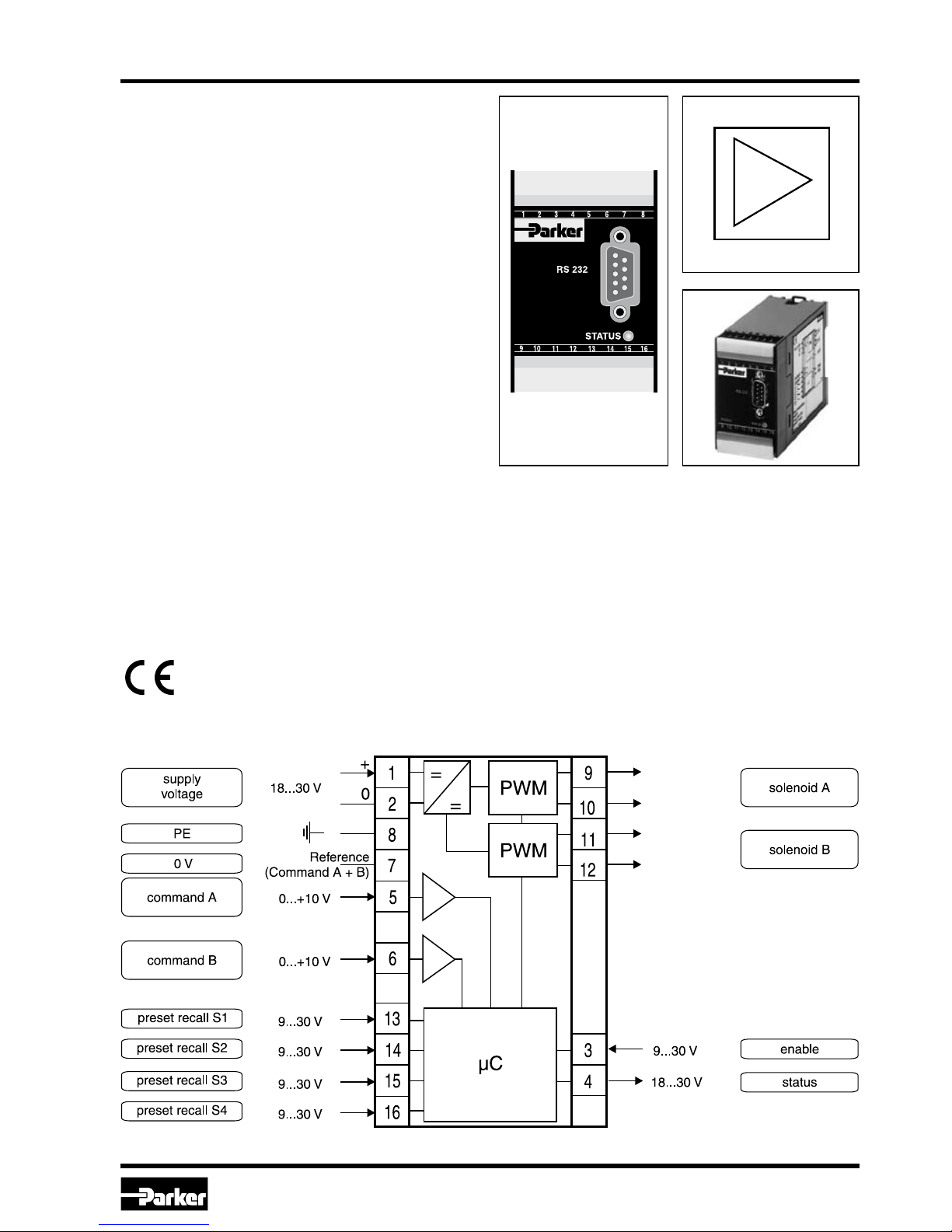
Parker electronic modules series PCD00A-400 for
rail mounting are compact, easy to install and
provide time-saving wiring by disconnectable terminals. The digital design of the circuit results in
good accuracy and optimal adaption for proportional pressure/flow control valves by a comfortable
interface program.
Features
The described electronic unit combines all necessary functions for the optimal operation of two
proportional pressure/flow control valves (series
R*V, RE*E*W, RE06M*W, DUR, PRPM, VBY, VMY,
TDA, TEA). The most important features are:
• Digitalcircuitdesign
• Twoindependentoperableampliers
• Fourparameterizablepresetrecallchannels
• Constantcurrentcontrol
• Twoinputstages0...10V
• Statusoutput
• Twoup/downrampfunctions
• Enableinputforsolenoiddriver
• Statusindicator
• ParameteringbyserialinterfaceRS232C
• Connectionbydisconnectableterminals
• Compatible to the relevant EuropeanEMC
standards
• ComfortablePCusersoftware,freeofcharge:
www.parker.com/euro_hcd
see "Support", or directly at
www.parker.com/propxd.
Page 4
4
PCD00A_19 3236-M1 UK.indd CM 10.02.16
Electronic Prop. Pressure/Throttle Valves
Series PCD 00A-400
Installation Manual
Parker Hannifin Corporation
Hydraulics Group
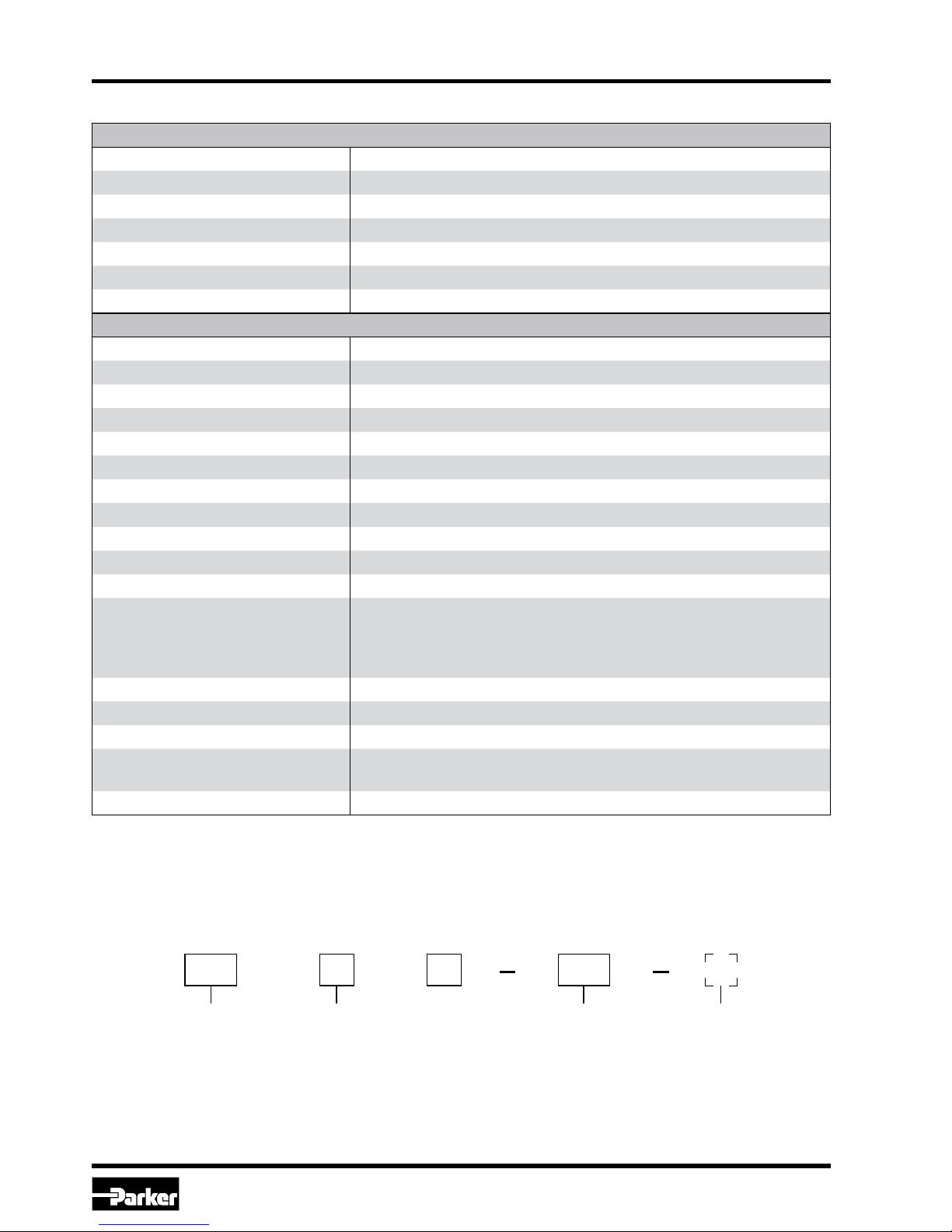
Technical Data
Electronic
module
prop. valve with
one solenoid
Design
series
(not required
for ordering)
Module type
Amplifier,
adjustable
min./max. limits
accel.-/decel.-ramp
2 x 2 internal pro-
grammable
commands
Variable
solenoid
current
Ordering Code
General
Model Module package for snap-on mounting on EN 50022 rail
Package material Polycarbonate
Inflammability class V0 acc. UL 94
Installation position Any
Ambient temperature range [°C] -20...+60
Protection class NEMA 1/IP20 acc. EN 60529
Weight [g] 160
Electrical
Duty ratio [%] 100
Supply voltage [VDC] 18...30, ripple < 5 % eff., surge free *)
Switch-on current typ. [A] 22 for 0.2 mS
Current consumption max. [A] 5.0
Pre-fusing [A] 6.3 A medium lag
Command signal [V] 0...+10, ripple < 0.01 % eff., surge free, Ri = 150 kOhm
Input signal resolution [%] 0,025
Differential input voltage max. [V] 30 for terminals 5 und 6 against PE (terminal 8)
Enable signal [V] 0...4.0: Off / 9.0...30: On / Ri = 30 kOhm
Channel recall signal [V] 0...4.0: Off / 9.0...30: On / Ri = 30 kOhm
Status signal [V] 0...0.5: Off / Us: On / rated max. 15 mA
Adjustment ranges Min
Max
Ramp
Current
[%]
[%]
[s]
[A]
0...50
50...100
0...32.5
0.8/1.3/1.8/2.7/3.5
Interface RS232C, DSub 9p. male for null modem cable
EMC EN 50081-2, EN 50082-2
Connection Screw terminals 0.2...2.5 mm², disconnectable
Cable specification
[AWG]
[AWG]
16 overall braid shield for supply voltage and solenoids
20 overall braid shield for sensor and signal
Cable length [m] 50
*) If solenoids with a nominal voltage of 24 V are connected, the supply voltage has to be raised to 29 V.
00PCD A 400
Page 5
PCD00A_19 3236-M1 UK.indd CM 10.02.16
Electronic Prop. Pressure/Throttle Valves
Series PCD 00A-400
Installation Manual
5
Parker Hannifin Corporation
Hydraulics Group
Commands
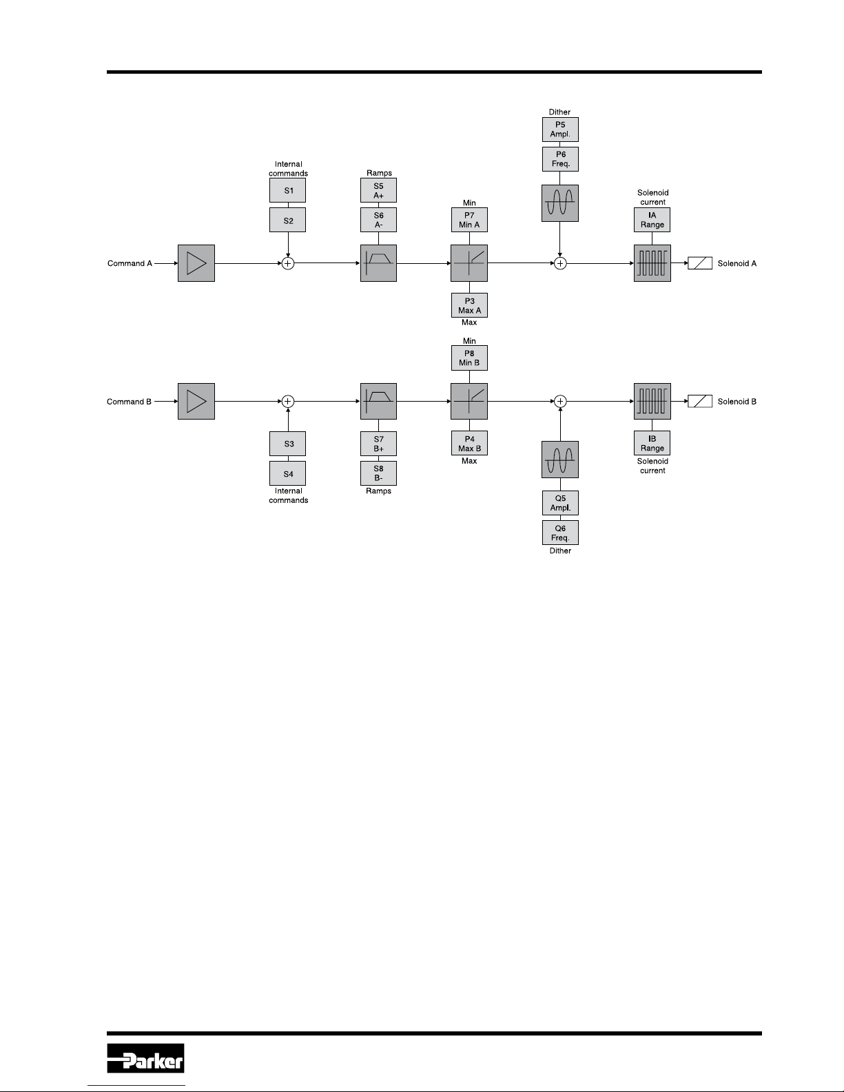
Additionally to the external analogue command
inputs (Pins 5-7 and 6-7), the PCD00A-400-electronic includes, for each channel, two internal
programmable command values S1 to S4, which
can be activated by the switching inputs (Pins 13,
14, 15, 16). S1 (Pin 13) has a higher priority than
Signal Flow Diagram A
S2 (Pin 14) and S3 (Pin 15) has a higher priority
than S4 (Pin 16).
If only one amplifier channel is used, it is possible
to switch all four internal commands to this channel
by setting parameter N=1.
Page 6
6
PCD00A_19 3236-M1 UK.indd CM 10.02.16
Electronic Prop. Pressure/Throttle Valves
Series PCD 00A-400
Installation Manual
Parker Hannifin Corporation
Hydraulics Group
Parameter Range
Default
value
Unit Function
P3 50.0...100.0 100.0 % max. current A-channel
P4 50.0...100.0 100.0 % max. current B-channel
P5 0.0...10.0 0.0 % Dither amplitude A-channel
P6 0...300 0 Hz Dither frequency A-channel
P7 0.0...50.0 0.0 % Min. current A-channel
P8 0.0...50.0 0.0 % Min. current B-channel
Q5 0.0...10.0 0.0 % Dither amplitude B-channel
Q6 0...300 0 Hz Dither frequency B-channel
S1 0.0...+100.0 0.0 % Internal command 1
S2 0.0...+100.0 0.0 % Internal command 2
S3 0.0...+100.0 0.0 % Internal command 3
S4 0.0...+100.0 0.0 % Internal command 4
S5 0...32500 0 ms Ramp UP A-channel
S6 0...32500 0 ms Ramp DOWN A-channel
S7 0...32500 0 ms Ramp UP B-channel
S8 0...32500 0 ms Ramp DOWN B-channel
IA 0, 1, 2, 3, 4 – –
Nominal current A-channel, 0=0.8 A; 1=3.5 A; 2=2.7 A; 3=1.8 A;
4=1.3A
IB 0, 1, 2, 3, 4 – –
Nominal current B-channel, 0=0.8 A; 1=3.5 A; 2=2.7 A; 3=1.8 A;
4=1.3 A
n 1, 2 2 – Allocation of internal command signals
All parameters are saved in an EEPROM and become active directly after supply voltage is switched on.
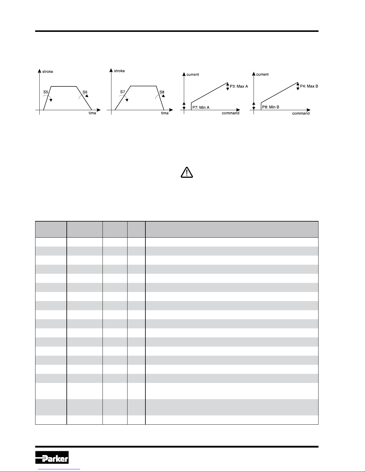
Ramp-function / Min-Max-function
The PCD00A-400-electronic includes two internal
programmable ramps for each channel. Addition-
ally a current step may be programmed (Min) and
/ or the current may be limited (Max) for each
Nominal current adjustment
The nominal current can be adjusted by one parameter separately for each channel (Pin 9, 10,
or 11, 12). The default nominal current is 800 mA.
Parameterization
All parameters can be adjusted via a serial connection (RS232C-null modem) by the computersoftware.
The computer-software shows the parameters in
textform. So they are easy to use.
The connected valves may not operated
before loading an appropriate parameter set
from the PC into the module electronics.
Example of parameter chart
Page 7
PCD00A_19 3236-M1 UK.indd CM 10.02.16
Electronic Prop. Pressure/Throttle Valves
Series PCD 00A-400
Installation Manual
7
Parker Hannifin Corporation
Hydraulics Group
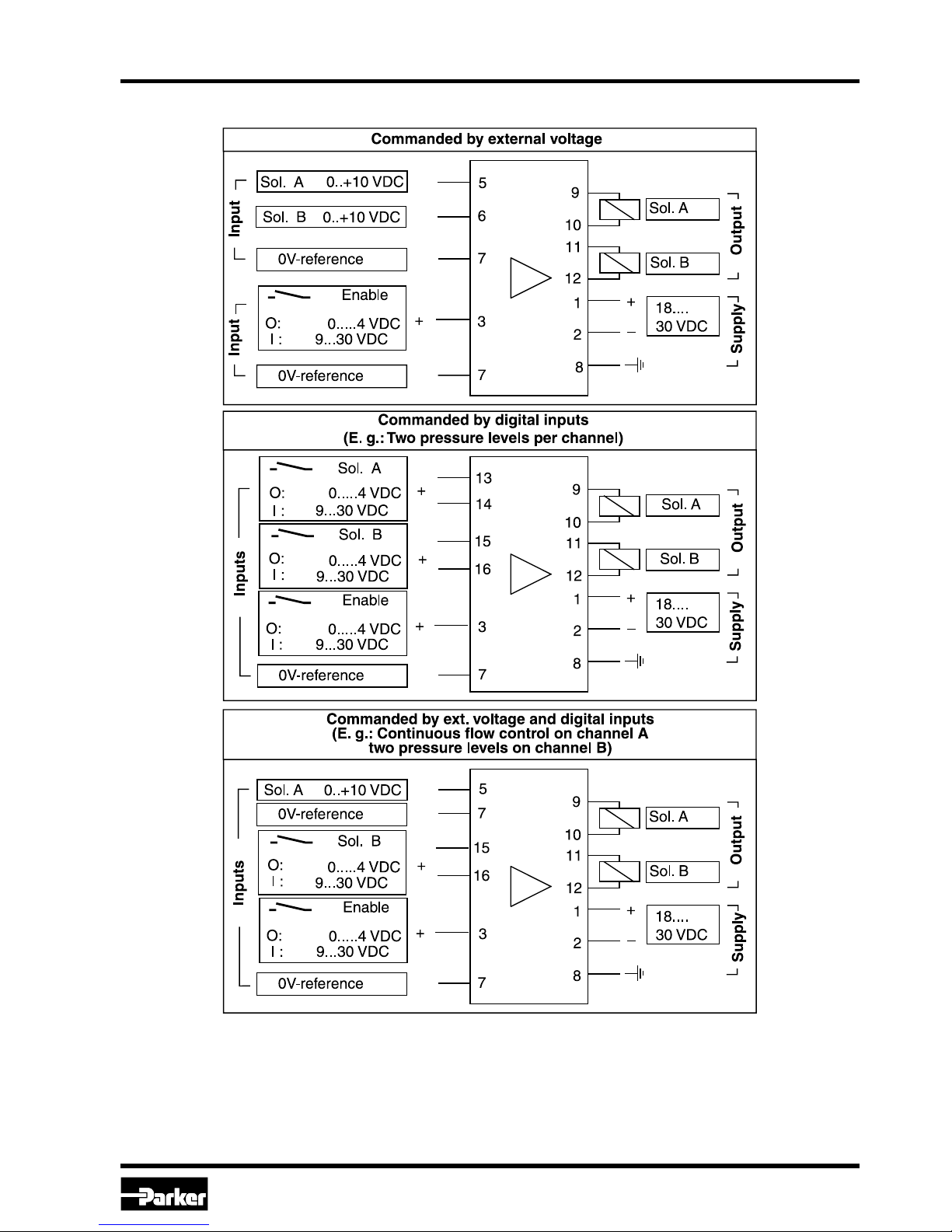
Connection Examples
Certainly combinations and / or modifications of these examples are possible. The priority of the digital
inputs over the analogue inputs has to be kept in mind! Via parameter N=1 all four digital inputs may
be dedicated to channel A.
Page 8
8
PCD00A_19 3236-M1 UK.indd CM 10.02.16
Electronic Prop. Pressure/Throttle Valves
Series PCD 00A-400
Installation Manual
Parker Hannifin Corporation
Hydraulics Group
Enable input and status output
The enable input activates (9...30 VDC) the power
amplifiers or deactivates them (0 VDC). The status
output delivers 18...30 VDC during normal operation.
It switches to 0 VDC in case of an error.
Valve Solenoid
Nominal Current Dither
I
max
A-side (IA) I
max
B-side (IB) Amplitude (P5) Frequency (P6)
TDA
L 1.3 A (4) a. P3=80.7 1.3 A (4) 1.6 21
M 2.7 A (2) 2.7 A (2) 0.8 21
DSA L 1.3 A (4) 1.3 A (4) 1.6 88
VBY/VMY
L 0.8 A (0) 0.8 A (0) 2.4 88
M 2.7 A (2) 2.7 A (2) 2.4 88
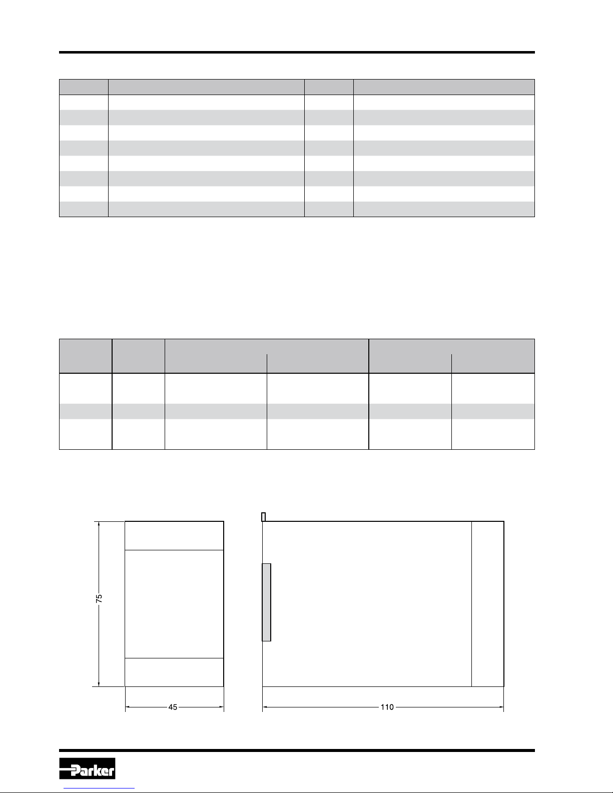
Dimensions
Pin Description Pin Description
1 + supply 18...30 VDC 9 channel A
2 GND supply 0 VDC 10 channel A
3 Enable input 9...30 VDC 11 channel B
4 Status output 0 VDC / 18...30 VDC 12 channel B
5 Cmd. A-channel 0...+10 VDC 13 int. command 1 0 VDC / 18...30 VDC
6 Cmd. B-channel 0...+10 VDC1 4 int. command 2 0 VDC / 18...30 VDC
7 GND cmds./dig.IO 0 VDC 15 int. command 3 0 VDC / 18...30 VDC
8 PE Earth 16 int. command 4 0 VDC / 18...30 VDC
Pinning
Please obey supply voltage (see technical data sheets).
Standard Parameters
Page 9

PCD00A_19 3236-M1 UK.indd CM 10.02.16
Electronic Prop. Pressure/Throttle Valves
Series PCD 00A-400
Installation Manual
9
Parker Hannifin Corporation
Hydraulics Group
Installation guide to electronic modules to provision of electromagnetic compatibility
Power Supply
The utilized power supply has to comply with the
EMC-standards (CE-sign, certificate of conformity).
Relais and solenoids operating from the same
supply circuit as the valve electronics have to be
fitted by surge protection elements.
Wiring Cable
The wires between the installation site of the module
and the peripheral units, as power supply, valve
solenoids, position transducer, command signal
source have to be shielded. The following wire
sizes must be reached: power supply AWG 16,
other connections AWG 20. The capacity should not
exceed a value of approx. 130 pF/m (wire/wire). The
maximum cable length is 50 m. No power current
lines may be placed within the wired shielded cables
to the electronic module. The cable shield has to be
connected to ground at both ends (see also chapter
“Grounding“). Please be aware of ground loops.
Installation
The module has to be mounted within a conductive,
shielded enclosure. Usable is i.e. an EMC-approved
control cabinet. A perfect grounding of the enclosure
is mandatory (see also chapter “Grounding“).
Grounding
The mounting plate of the valve has to be connected to the grounded metal machine frame. The
cable shields must be tied to ground at the control
cabinet. A low-ohmic potential compensation wire
has to be provided between the control cabinet
and the machine frame (cable wire >AWG 7 cross
section) to prevent ground loops.
Page 10

 Loading...