

Page 1
Catalog 0700P-E
P31P / P32P Series
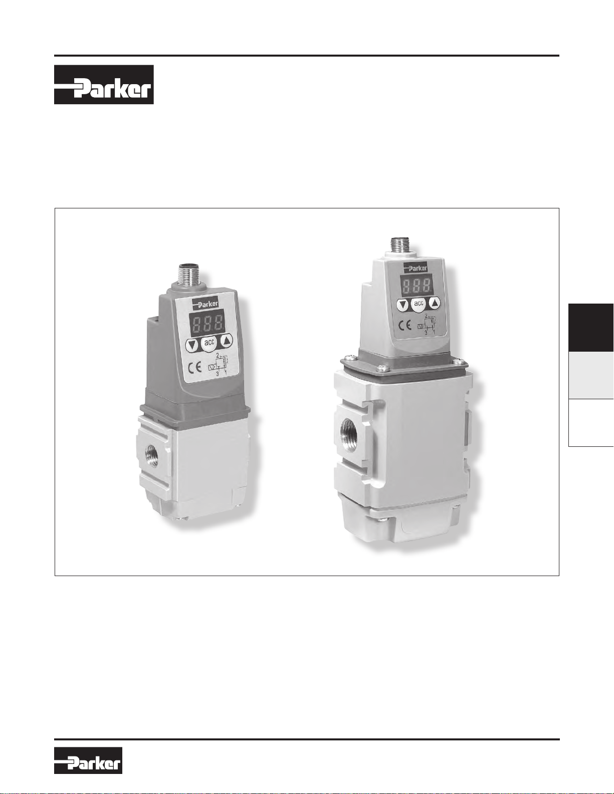
Electronic Proportional Regulators
P31P / P32P Series
Electronic Proportional Regulator
0 to 10 volt, 4 to 20 mA
Proportional Regulator Applications .....................F4-F5
Features & Benefits ...................................................F6
Ordering Information .................................................F7
Technical Information............................................F8-F9
Programming Information .................................F10-F15
Dimensions ..............................................................F16
Troubleshooting .......................................................F17
Glossary ..................................................................F18
F
P31P / P23PPAR15
F3
www.comoso.comwww.comoso.com
Parker Hannifin Corporation
Pneumatic Division
Richland, Michigan
www.parker.com/pneumatics
Page 2
Catalog 0700P-E
Applications
P31P / P32P Series
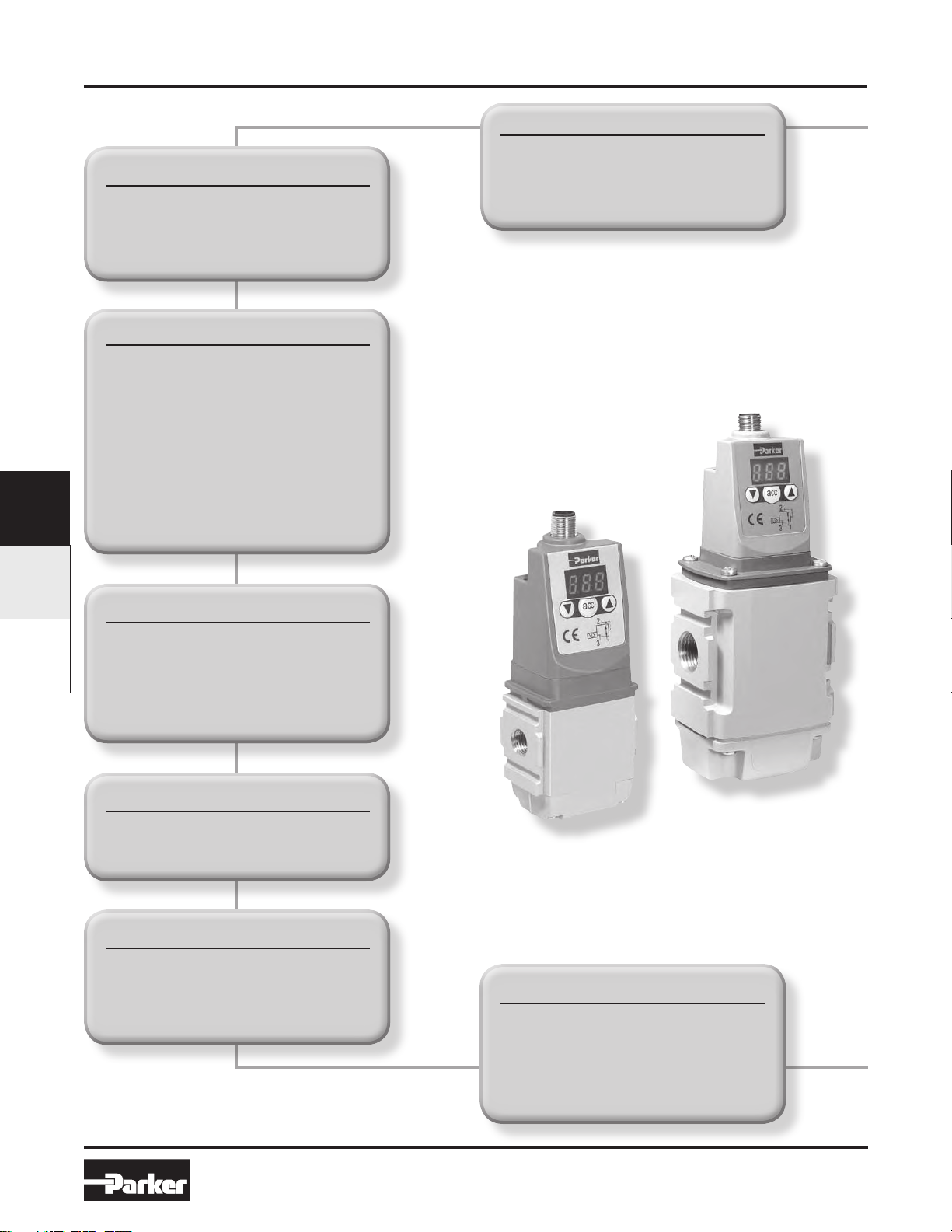
Electronic Proportional Regulators
F
P31P / P32P PAR15
Man-Machine Interface
High Visibility LED Display
Easy to Read Characters
All Controls on the Same Face
Total Flexibility
User Friendly and Easily
Accessible Software Controls
One Basic Unit Suits All
Customer Requirements -
0-10V Control Signal Standard
4-20mA Control Signal Software
Selectable
Modular Mounting
10 bar & 2 bar Version
Energy Saving
Low Watt Power Consumption
No Unnecessary Loss of Air in
Steady State
Special Applications
Clean Line Design
Suitable for Washdown: IP65
Forced Exhaust Option Available
4 Output Signal Versions Available
Compact and Light Weight
40 & 60 mm Body Sizes
Light Weight Aluminum Bodies
Flexible Mounting Options
Stand-alone or Modular Mounting
Foot Bracket Mounting
DIN-Rail Mounting
Outstanding Performance
Very Fast Response Times
Full Flow Exhaust
Excellent Linearity
High Flow
F4
www.comoso.comwww.comoso.com
Parker Hannifin Corporation
Pneumatic Division
Richland, Michigan
www.parker.com/pneumatics
Page 3
Catalog 0700P-E
Applications
P31P / P32P Series
Electronic Proportional Regulators
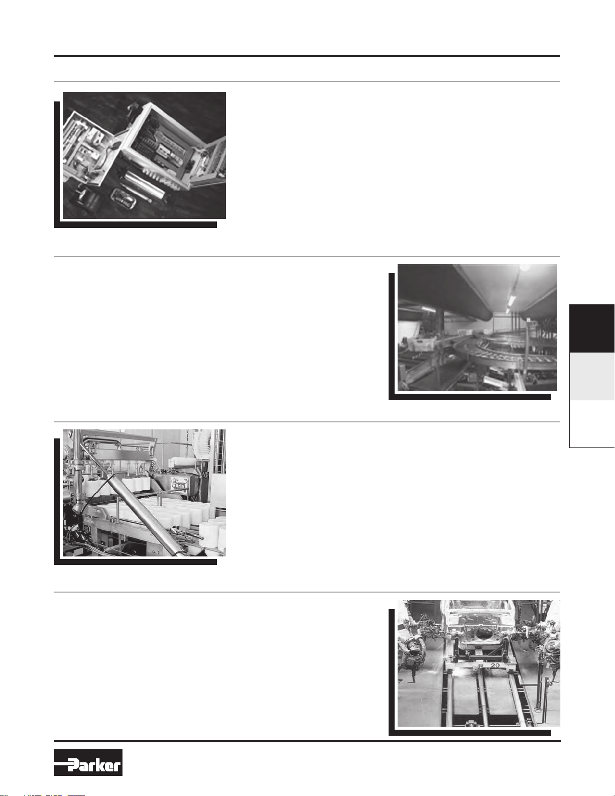
Generic Industries
The new Proportional Regulator is designed to quickly and accurately
adjust and maintain a set output pressure.
The unit will operate regardless of flow, in response to an electronic
control signal. The media can be compressed air or an inert gas.
Applications for this technology are virtually unlimited; from paint spray
control, paper manufacturing and printing to weaving and laser cutting
control; in fact anywhere that requires accurate remote pressure control.
Automation
In the field of general automation, the need to control processes or
movement via electronic signals is of paramount importance. The
Proportional Regulator unit provides the facility to incorporate pressure
control into a fully integrated control system.
Packaging and Food
The Packaging and Food industry provides another ideal area for
application of the Electronic Proportional Regulator, where fine control
of tension on wrapping foils and paper is required. The degree of control
and the ability to manually change parameters makes this unit ideally
suited to the varying requirements of this industry.
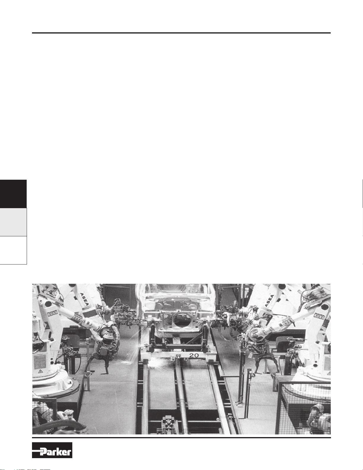
Automotive
Applications for this innovative product in the Automotive industry can
be seen in major manufacturers’ “body-in-white” lines.
The control of clamping and welding forces during panel assembly is
an ideal application, also accurate control in paint dipping and spraying
can be achieved.
F
P31P / P23PPAR15
F5
www.comoso.comwww.comoso.com
Parker Hannifin Corporation
Pneumatic Division
Richland, Michigan
www.parker.com/pneumatics
Page 4
Catalog 0700P-E
Features & Benefits
Why Proportional Technology?
P31P / P32P Series
Electronic Proportional Regulators
The Difference Between Open or
Closed Circuit Control
Standard pressure regulators go a long way towards
meeting customers needs. In most cases these
regulators work well in general pneumatic and
automation applications. However, sometimes the
application calls for more precise pressure control.
The effects of time, cycling, input, back pressure or
pressure and flow variation can all cause inconsistencies
in pneumatic systems. Proportional Regulators are
designed to eliminate those inconsistencies.
Open Control Circuit
In a normal pressure regulated control system, the inlet
pressure (p1) is converted into the output pressure
(p2) by the regulator. The set pressure (set value) is
usually manually set by adjusting the control knob and
in normal circumstances the regulator maintains the
output pressure (actual value).
F
No facility for monitoring the output pressure is
P31P / P32P PAR15
provided and there is consequently no way of checking
that the set value and the actual value are the same.
Also, no account is taken of external influences such as
air consumption by the system, which can drastically
alter the actual value.
Closed Loop Control Circuit
The input signal (Electronic Control Signal) is
converted into the output value (P2 Output Pressure).
This output value is continuously measured and
compared with the input signal. If they are different, the
unit adjusts the output value to correspond to the set
value, to close the loop.
Proportional Pressure Regulators
The Proportional Regulators provide all the advantages
of a closed circuit regulated system. When a set value
is defined via the input signal (e.g. 0-10 V), the pressure
regulator sets the corresponding output pressure (e.g.
0-150 PSI/0-10 bar). At the same time the integrated
pressure sensor measures the actual pressure at the
unit’s outlet (actual value).
If the electronic regulation system finds that the actual
value has deviated from the set value, it immediately
corrects the actual value. This is a continuous process
ensuring fast, accurate pressure regulation.
Typical Application in Automotive Body in
White Welding Pressure Control
F6
www.comoso.comwww.comoso.com
Parker Hannifin Corporation
Pneumatic Division
Richland, Michigan
www.parker.com/pneumatics
Page 5
Catalog 0700P-E
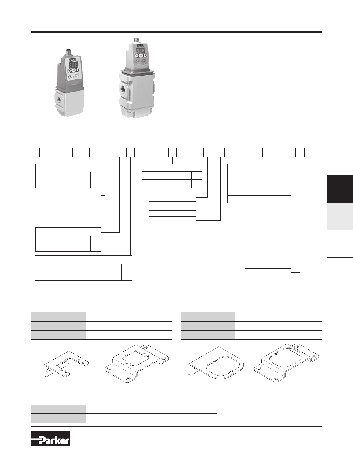
Ordering Information
P31P Series
Bottom exhaust
Ordering Information
P AP 3 1 A 2 1 A
P32P Series
Bottom exhaust
P31P / P32P Series
Electronic Proportional Regulators
Features
• Very fast response times
• Accurate output pressure
• Micro parameter settings
• Selectable I/O parameters
• Quick, full flow exhaust
• LED display indicates output pressure
• No air consumption in steady state
• Multiple mounting options
• Protection to IP65
• P31P flows to 19 dm3/s (40 scfm)
• P32P flows to 57 dm3/s (120 scfm)
Body size
Global Mini (1/4") 1
Global Compact (1/2")
2
Pressure Range
0 - 2 bar (0-29 psig) Z
0 - 10 bar (0-145 psig)
Thread type
BSPP 1
2
BSPT
NPT
9
Port size
Global Mini (1/4") 2
Global Compact (1/2")
4
†
control signal. 4-20 mA
control signal available via
parameter 4 on keypad.
Version
Bottom ported exhaust (NC) A
Bottom ported forced exhaust (NO)*
* When the supply voltage is lost the unit will automatically
exhaust the regulated pressure to 0 bar
(atmospheric pressure)
E
P31P Mounting Brackets
Order Code Description
P3HKA00ML L-Bracket mounting kit
P3HKA00MC Foot bracket mounting kit
Power supply
24 volts 2
Control Signal
0-10 V† V
Factory setting is 0-10 V
P32P Mounting Brackets
Order Code Description
P3KKA00ML L-Bracket mounting kit
P3KKA00MC Foot bracket mounting kit
D
Output Signal
Digital, PNP D
PNP or 0-10V
NPN or 0-10V
4-20mA fixed
D) Digital PNP output only, no analog
output selectable
P) Digital PNP and analogue 0-10V
outputs selectable, by means of
parameter 6. (Factory default 0-10V)
N) Digital NPN and analog 0-10 V
outputs selectable by means of
parameter 6. (Factory default 0-10V)
M) Analog 4-20mA output only.
Note: On all analog outputs the F.S.
value can be adjusted by means of
parameter 8
P
N
M
Input connector
M12 (4 pin) 1
F
P31P / P23PPAR15
L-Bracket Foot BracketL-Bracket Foot Bracket
Cables
Order Code Description
CB-M12-4P-2M 2 mtr. cable with moulded straight M12x1 connector
F7
www.comoso.comwww.comoso.com
Note:
These brackets fit both Proportional
Regulators and Combined Soft Start
& Dump Valves.
Parker Hannifin Corporation
Pneumatic Division
Richland, Michigan
www.parker.com/pneumatics
Page 6
Catalog 0700P-E
VER)
(Revised 03-28-13)
Technical Information
Technical Information
Working media
Compressed air or inert gasses, filtered to Min. 40µ,
lubricated or non-lubricated, dried or un-dried,
pressure dewpoint 3-5°C.
Operating pressure
Max. Operating Pressure
2 bar unit ...............................................3 bar (43.5 PSI)
10 bar unit ........................................10.5 bar (152 PSI)
Min. Operating Pressure ............P2 Pressure + 0.5 bar
Pressure control range
Available in three pressure ranges, 0-2 bar, 0-7 bar or
0-10 bar. Pressure range can be changed through the
software at all times. (parameter 19)
Temperature range
32°F to 122°F (0°C to 50°C)
Weight
P31P = 0.291 kg (0.64 lbs)
P32P = 0.645 kg (1.42 lbs)
F
Air consumption
P31P / P32P PAR15
No consumption in stable regulated situation.
P31P / P32P Series
Electronic Proportional Regulators
Supply voltage
24 VDC +/- 10%
Power consumption
Max. 1.1W with unloaded signal outputs
Control signals
The electronic pressure regulator can be externally
controlled through an analogue control signal of either
0-10V or 4-20mA. (parameter 4).
Output signals
As soon as the output pressure is within the signal
band a signal is given of 24V DC, PNP Ri = 1 kOhm
Outside the signal band this connection is 0V.
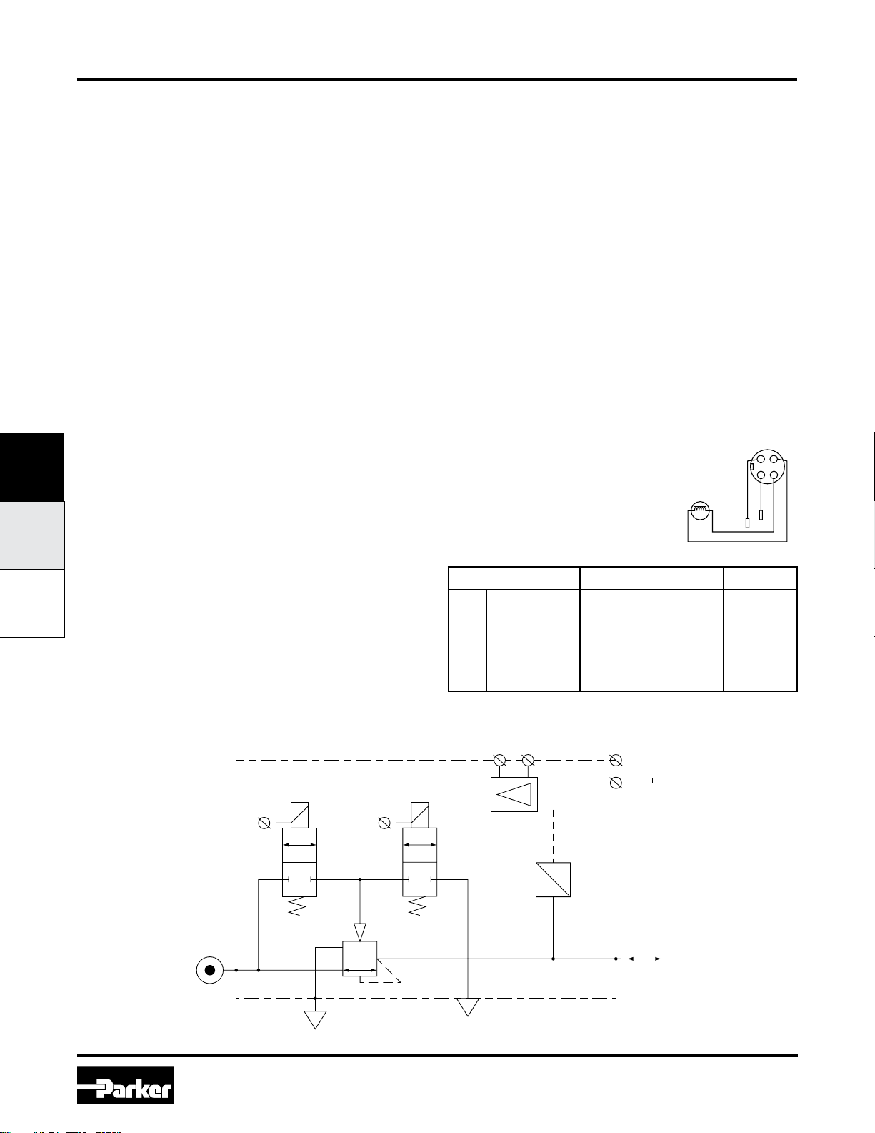
Connections
(In case of output signal (Option D)
Central M12 connector 4-pole
ISO 20401
4-PIN MICRO
(TOP CO
BRN
134
2
WHT
BLUE
BLK
Display
The regulator is provided with a digital display,
indicating the output pressure, either in PSI or bar.
The factory setting is as indicated on the label, can be
changed through the software at all times (parameter
14).
Schematic
1
24 VDC
The electrical connections are as follows:
Pin No. Function Color
1 24 V Supply Brown
0 to 10 V Control Signal Ri = 100k W
2
4 to 20mA Control Signal Ri = 500 W
3 0 V (GND) Supply Blue
4 24 V Alarm Output Signal Black
+
O
Control
Signal
U
P
2
White
3
F8
www.comoso.comwww.comoso.com
Parker Hannifin Corporation
Pneumatic Division
Richland, Michigan
www.parker.com/pneumatics
Page 7

Catalog 0700P-E
Technical Information
P31P / P32P Series
Electronic Proportional Regulators
Technical Information
Dead Band
The dead band is preset at 1.3% of Full Scale*, adjustable via
parameter 13.
Accuracy
Linearity: = < 0.3% of Full Scale.*
Proportional Band
The proportional band is preset at 10% of Full Scale.*
Fail Safe Operation
• If the P31P / P32P unit has an “0” or “A” in the 12th digit of
the model number
– When the supply voltage drops, the electronic control
reverts to the fail safe mode. The last known output
pressure air consumption. The digital display
indicates the last known pressure setting.
– When the supply voltage is reinstated to the correct
level, the valve moves from the fail safe mode and the
output pressure immediately follows the control signal
requirement. The display indicates the actual output
pressure.
– Note: In the event of loss of both power and inlet
pressure the unit will exhaust downstream pressure.
• If the P31P / P32P unit has an “E” in the 12th digit of the
model number
– When the supply voltage drops, the electronic control
reverts to “Forced Exhaust Mode” and will automatically
exhaust the downstream (regulated) pressure.
– When the supply voltage is reinstated to the correct
level the unit will return to normal operation and follows
the control signal requirement. The display indicates
the actual pressure.
• If the unit has been programmed in manual mode (not with
a control signal) the unit will EXHAUST and the regulator
will need to be reset when power is applied.
Full Exhaust
Complete exhaust of the regulator is defined as P2 ≤ 1% Full Scale
* Full Scale (F.S.)
For 2 bar (29 psig) versions this will be 2 barr (29 psig), for the 10
bar (145 psig) version full scale will be 10 bar (145 psig).
Degree of Protection
IP65
EU Conformity
CE: standard
EMC: according to directive 89/336/EEC
The new pressure regulator is in accordance with:
EN 61000-6-1:2001 EN 61000-6-2:2001
EN 61000-6-3:2001 EN 61000-6-4:2001
These standards ensure that this unit meets the highest level of EMC
protection.
Mounting Position
Preferably vertical, with the cable gland on top.
Materials: P31P & P32P
• Magnet Core ............................................................................Steel
• Solenoid Valve Poppet ............................................................. FPM
• Solenoid Valve Housing .........................................Techno Polymer
• Regulator Body (P31P & P32P versions) .......................Aluminium
• Regulator Top Housing ...........................................................Nylon
• Valve Head .................................................................Brass & NBR
• Remaining Seals .....................................................................NBR
Advanced Functionality
Pilot valve protection
When the required output pressure can not be achieved because of
a lack of input pressure the unit will open fully and will display NoP.
Approximately every 10 seconds the unit will retry. The output pressure will then be approximately equal to the inlet pressure. As soon
as the input pressure is back on the required level, the normal control
function follows.
Safety exhaust
Should the control signal fall below 0.1 volts the valve will automatically dump downstream system pressure .
Input protection
The unit has built-in protection against failure and burnout resulting
from incorrect input value, typically:
The 24VDC supply is incorrectly connected to the setpoint input, the
display will show ‘OL’, as an overload indication. The unit will need to
be rewired and when correctly connected will operate normally.
The overload indicator ‘OL’ will also appear should the wrong input
value be applied or the wrong input value be programmed: 4 - 20m
instead of 0 - 10V. To correct this a different set point value should
be input or the unit reprogrammed to correct the set point value
acceptance. (via parameter 4).
Response time P31P P32P
2 to 4 bar 25 msecs 35 msecs
1 to 6 bar 55 msecs 135 msecs
4 to 2 bar 70 msecs 85 msecs
6 to 1 bar 80 msecs 225 msecs
To fill volume of:
3
100cm
- P31P
330cm3 - P32P
connected to the outlet of the regulator.
Settings
The regulator is pre-set at the factory. If required, adjustments can
be made.
Flow Charts
P31P Regulator 1/4” Ports
P32P Regulator 1/2” Ports
Inlet Pressure - 10 bar (145 psig)
10
140
9
120
8
7
100
6
80
5
60
4
3
40
2
Secondary Pressure - bar
Secondary Pressure - (psig)
20
1
0
0
0
Inlet Pressure - 10 bar (145 psig)
10
140
9
120
8
7
100
6
80
5
60
4
3
40
2
Secondary Pressure - bar
Secondary Pressure - (psig)
20
1
0
0
0
0
5 10 15 20 25 30 35
10 20 30 40 50 60 70
20 60
40
80 100 120 140 180160
3
/s
Flow - dm
Flow - (scfm)
60 7010 504020 80 9030 100
3
/s
Flow - dm
Flow - (scfm)
200
F
P31P / P23PPAR15
F9
www.comoso.comwww.comoso.com
Parker Hannifin Corporation
Pneumatic Division
Richland, Michigan
www.parker.com/pneumatics
Page 8
Catalog 0700P-E
or
or
or
or
Programming Information
P31P / P32P Series
Electronic Proportional Regulators
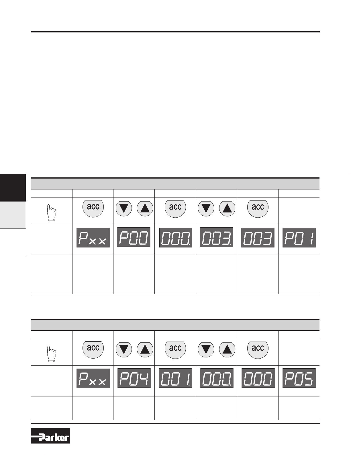
How to Change Parameters
Pressing the Accept key “acc” for more than 3 seconds, will
activate parameter change mode. The user can then select
the parameters by pressing up or down key. (display will
show Pxx). When parameter number is correct, pressing
accept again will enter parameter number.(display will show
parameter value).
Pressing the up or down key will change the parameter
itself. (display will flash indicating parameter editing mode).
Pressing the accept key will accept the new parameter value.
(all digits will flash whilst being accepted).
After releasing all keys , the next parameter number will
be presented on the display. (you may step to the next
parameter). When no key is pressed, after 3 seconds the
display will show the actual output pressure.
Back to Factory Setting
After start up. (Power is on)
Entering this value in parameter 0 will store the calibrated factory data into the working parameters.
(Default calibration data is used)
When the unit is initially powered up allow approximately 10
seconds for the unit to “boot-up” before changing parameter
settings.
Only parameter numbers 0, 4, 6, 8, 9, 14, 18, 19, 20, 12, 13
and 21 are accessible to edit. All other parameters are fixed.
Manual mode:
When keys DOWN and UP are pressed during startup,
(connecting to the 24V power supply) manual mode is
activated. This means that the user is able to in/decrease
the output pressure of the regulator, by pressing the UP or
DOWN key. During this action the display will blink, indicating
that the manual mode is activated. After powering up again,
the unit will revert back to normal mode.
Parameter Number 0 – Reset Back to Factory Settings
F
P31P / P32P PAR15
Step 1 2 3 4 5
Press
3-6 seconds
Until Display
Reads
Flashing Decimal Flashing Decimal Flashing
Edits parameter.
3 = standard
factory settings.
Description
Accesses
changeable
parameters.
Accesses
parameter no. 0.
Displays current
parameter value.
If other than 3,
use Up or Down
Arrow and
accept 3
Set Control Signal
The unit is factory set for 0-10 V control signal. If 4-20 mA control signal is required, change parameter 4.
Accepts and
saves new
parameter
Parameter Number 4 – Set Control Signal in Volts or Milliamps
Step 1 2 3 4 5
Press
setting.
Sequences to
next parameter.
3-6 seconds
Until Display
Reads
Flashing Decimal Flashing Decimal Flashing
Displays current
parameter value.
1 = V
0 = mA
Edits parameter.
Description
Accesses
changeable
parameters.
Accesses
parameter no. 4.
F10
www.comoso.comwww.comoso.com
Accepts and
saves new
parameter
setting.
Parker Hannifin Corporation
Pneumatic Division
Richland, Michigan
www.parker.com/pneumatics
Sequences to
next parameter.
Page 9
Catalog 0700P-E
or
or
or
or
Programming Information
P31P / P32P Series
Electronic Proportional Regulators
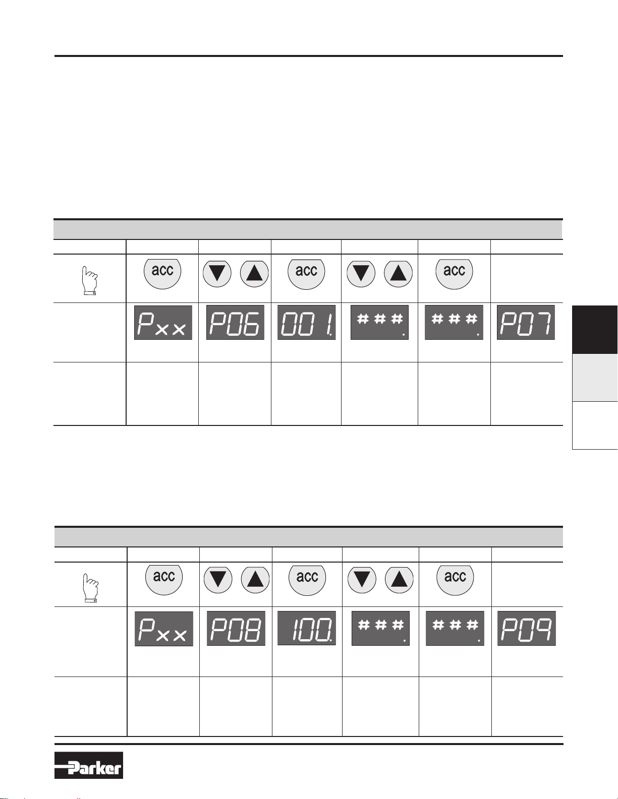
Set Output Signal
Parameter 6 is used to set the type of output signal to your PLC.
This parameter is used as follows:
Output Signal option “0” = Digital Output – PNP
• Factory set at “0” Non Adjustable
Output Signal option “P” = Digital PNP or Analog 1-10V
• Factory set at “1” for Analog Signal
• Convert to Digital PNP by changing parameter to “0” setting
Output Signal option “N” = Digital NPN or Analog 1-10V
• Factory set at “1” Analog Signal
• Convert to Digital NPN by changing parameter to “0”
Output Signal option “M” = Analog 4-20 mA
• Factory set at “2” Non Adjustable
Parameter Number 6 – Set Output Signal
Step 1 2 3 4 5
Press
3-6 seconds
Until Display
Reads
Flashing Decimal
(Value 0, 1 or 2) Flashing
Edits parameter.
0 = digital
(NPN or PNP)
1 = analog 0..10V
2 = analog 4..20 mA
Description
Accesses
changeable
parameters.
Accesses
parameter no. 6.
Flashing Decimal
Displays current
parameter value.
1 = m factory
default for P3H
with analog
options
Accepts and
saves new
parameter
setting.
F
P31P / P23PPAR15
Sequences to
next parameter.
Adjust Span Analog Output Signal
Set value is a % of Full Analog range. As an example for a 0-10V output signal, the original factory setting of 100% will give you an adjustment
of 0-10V. If you reset Parameter 8 to 50%, the new output range would be 0-5V or 50% of the full range.
In the event that the output signal is to low, in a certain application, you can adjust it by increasing Parameter 8 to a maximum value of 130% of
scale.
Note that all values are nominal and that an actual measurement may be required to ensure signal strength.
Parameter Number 8 – Adjust Span Analog Output Signal
Step 1 2 3 4 5
Press
3-6 seconds
Until Display
Reads
Description
Accesses
changeable
parameters.
Accesses
parameter no. 8.
Flashing Decimal
(For 2 bar versions
value = 92)
Displays current
parameter value. Edits parameter.
Flashing Decimal
(Value between
0 and 130) Flashing
Accepts and saves
new parameter
setting and
implements the
new analog signal
span.
Sequences to
next parameter.
F11
www.comoso.comwww.comoso.com
Parker Hannifin Corporation
Pneumatic Division
Richland, Michigan
www.parker.com/pneumatics
Page 10
Catalog 0700P-E
or
or
or
or
Programming Information
P31P / P32P Series
Electronic Proportional Regulators
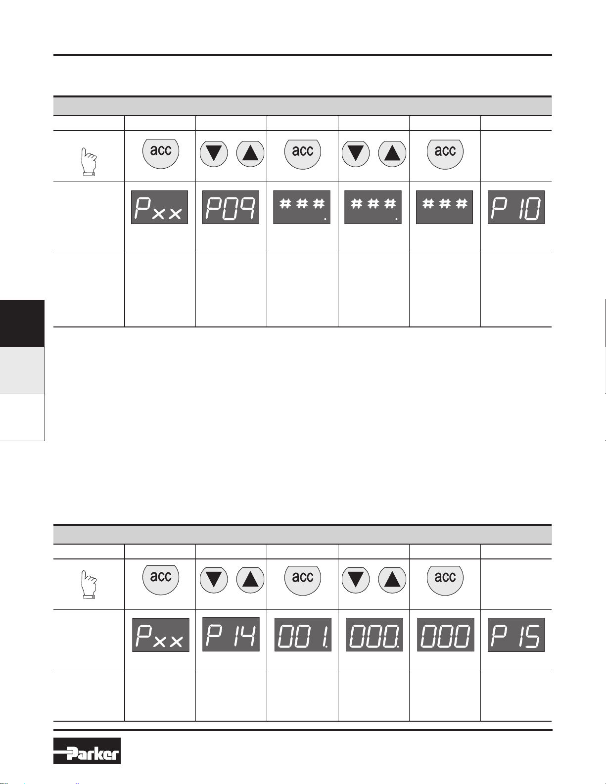
Adjust Digital Display
If necessary, adjustments can be made to the digital display when using an external pressure sensor.
Parameter Number 9 – Adjust Digital Display Value (Pressure Calibration)
Step 1 2 3 4 5
Press
3-6 seconds
Until Display
Reads
Flashing Decimal Flashing Decimal Flashing
Use up or down
arrows and
Description
Accesses
changeable
parameters.
Accesses
parameter no. 9.
Displays current
digital display
accept to adjust
the display
value if using an
external pressure
sensor.
Accepts and
saves new
parameter
setting.
F
Sequences to
next parameter.
P31P / P32P PAR15
Set Pressure Scale
Units with NPT port threads are supplied with a factory set psig pressure scale. Use parameter 14 to change scale to bar.
Parameter Number 14 – Set Pressure Scale in psig or bar
Step 1 2 3 4 5
Press
3-6 seconds
Until Display
Reads
Flashing Decimal Flashing Decimal Flashing
Displays current
Description
Accesses
changeable
parameters.
Accesses
parameter no. 14.
parameter value.
1 = psig
0 = bar
2 = MPA
Edits parameter.
F12
www.comoso.comwww.comoso.com
Accepts and
saves new
parameter
setting.
Parker Hannifin Corporation
Pneumatic Division
Richland, Michigan
www.parker.com/pneumatics
Sequences to
next parameter.
Page 11
Catalog 0700P-E
or
or
or
or
Programming Information
P31P / P32P Series
Electronic Proportional Regulators
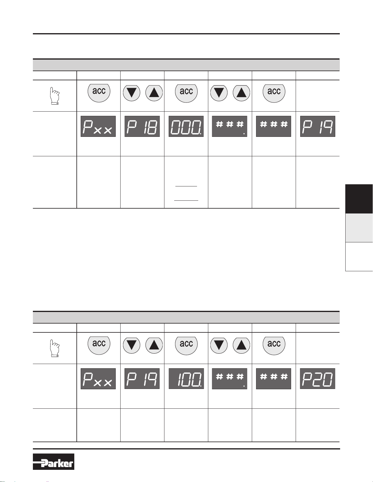
Preset Minimum Pressure
If there is a need for a pre-set Minimum pressure, use parameter 18. (Note: preset pressure is affected by % P19.)
Parameter Number 18 – Set Minimum Preset Pressure
Step 1 2 3 4 5
Press
3-6 seconds
Until Display
Reads
Flashing Decimal
(value between
0 and 200)
Edits parameter.
Flashing
Accepts and
saves new
parameter
setting.
Description
Accesses
changeable
parameters.
Accesses
parameter no. 18.
Flashing Decimal
Displays current
parameter value.
Incremental
value is:
2 bar unit:
x 2 mbar x % P19
10 bar unit:
x 10 mbar x % P19
Sequences to
next parameter.
F
Set Pressure Correction
Pressure correction allows the user to set a Maximum pressure as a percentage of secondary pressure F.S.
Example: If F.S. is 10 bar, set parameter 19 to 50 for Maximum preset pressure of 5 bar.
Pressure correction also affects the Minimum preset pressure in parameter 18.
Example: If F.S. is 10 bar and parameter 18 is set to a value of 100 (1 bar), and parameter 19 is set to 50%, then the actual Minimum preset
pressure seen is 0.5 bar.
Parameter Number 19 – Set Maximum Preset Pressure
Step 1 2 3 4 5
Press
3-6 seconds
Until Display
Reads
Flashing Decimal
(value between
0 and 100)
Flashing
Accepts and
saves new
parameter
setting.
Sequences to
next parameter.
Description
Accesses
changeable
parameters.
Accesses
parameter no. 19.
Flashing Decimal
Displays current
parameter value.
Incremental
value is:
% of F.S. Edits parameter.
P31P / P23PPAR15
F13
www.comoso.comwww.comoso.com
Parker Hannifin Corporation
Pneumatic Division
Richland, Michigan
www.parker.com/pneumatics
Page 12
Catalog 0700P-E
or
or
or
or
Programming Information
P31P / P32P Series
Electronic Proportional Regulators
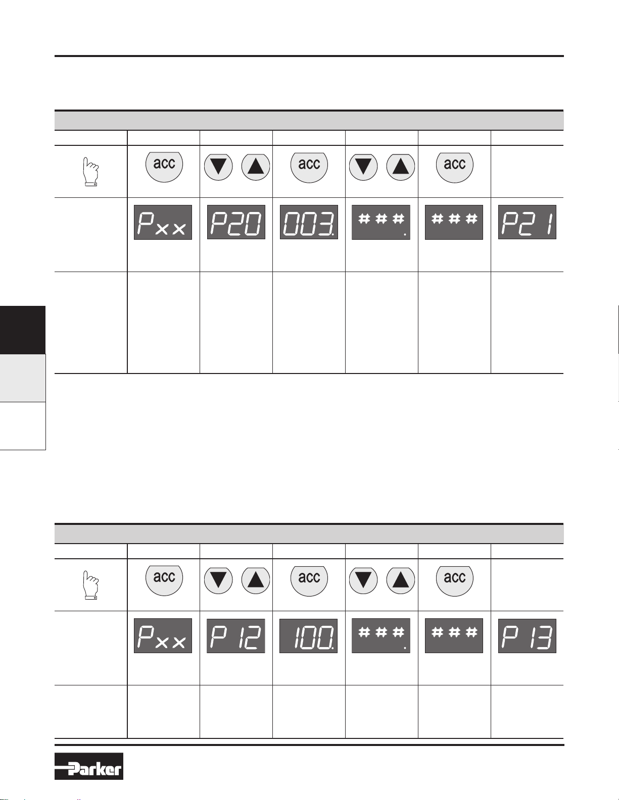
Behavior Control
The regulation speed of the pressure regulator can be modified by means of one parameter. (P 20)
The value in this parameter has a range from 0-5. A higher value indicates slower regulation speed, but will be more stable.
Parameter Number 20 – Set Behavior Control
Step 1 2 3 4 5
Press
3-6 seconds
Until Display
Reads
Flashing Decimal
(value between
0 and 5)
Edits parameter
0 = custom set*
1 = fastest (narrow
proportional band)
2 = fast
3 = normal
4 = slow
5 = slowest
(proportional
band is broad)
F
P31P / P32P PAR15
Description
Accesses
changeable
parameters.
Accesses
parameter no. 20.
Flashing Decimal
Displays current
parameter value.
Flashing
Accepts and
saves new
parameter
setting.
Sequences to
next parameter.
* When the value 0 is entered, you are able to create your own custom settings true parameters 12, 13 and 21.
Fine Settings
Set Proportional Band
Proportional band is used for setting the reaction sensitivity of the regulator. The displayed value is X 10 mbar and has a range between 50
(0.5 bar) and 250 (2.5 bar).
Parameter Number 12 – Set Proportional Band (P20 Must be Set to 0)
Step 1 2 3 4 5
Press
3-6 seconds
Until Display
Reads
Flashing Decimal
(value between
50 and 250)
Edits parameter.
Flashing
Accepts and
saves new
parameter
setting.
Sequences to
next parameter.
Description
Accesses
changeable
parameters.
Accesses
parameter no. 12.
Flashing Decimal
Displays current
parameter value.
Incremental
value is:
x 10 mbar
F14
www.comoso.comwww.comoso.com
Parker Hannifin Corporation
Pneumatic Division
Richland, Michigan
www.parker.com/pneumatics
Page 13
Catalog 0700P-E
or
or
or
or
or
Programming Information
P31P / P32P Series
Electronic Proportional Regulators
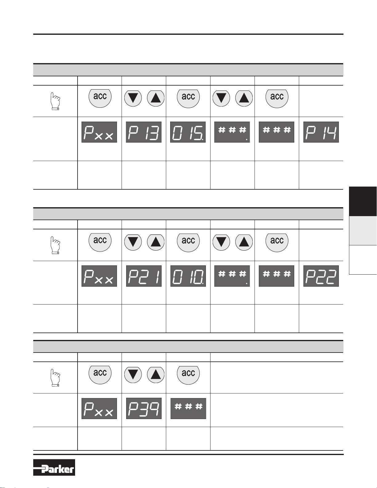
Set Deadband
Deadband is the Minimum limit of accuracy at which the regulator is set for normal operation. The displayed value is X 10 mbar and has a range
between 4 (40 mbar) and 40 (400 mbar).
Parameter Number 13 – Set Deadband (P20 Must be Set to 0)
Step 1 2 3 4 5
Press
3-6 seconds
Until Display
Reads
Flashing Decimal
(value between
4 and 40)
Edits parameter.
Flashing
Accepts and saves
new parameter
setting.
Sequences to next
parameter.
Description
Accesses
changeable
parameters.
Accesses
parameter no. 13.
Flashing Decimal
Displays current
parameter value.
Incremental
value is
x 10 mbar
Proportional Effect
Parameter Number 21 – Set Proportional Effect (P20 Must be Set to 0)
Step 1 2 3 4 5
Press
3-6 seconds
Until Display
Reads
Flashing Decimal
(value between
5 and 100)
Edits parameter.
5 = fastest
regulation
100 = slowest
regulation.
Flashing
Accepts and
saves new
parameter
setting.
Sequences to
next parameter.
Description
Accesses
changeable
parameters.
Accesses
parameter no. 21.
Flashing Decimal
Displays current
parameter value.
Parameter Number 39 – Displays Current Software Version
Step 1 2 3
Press
F
P31P / P23PPAR15
3-6 seconds
Until Display
Reads
Flashing Decimal
Description
Accesses
changeable
parameters.
Accesses
parameter no. 39.
Displays current
parameter value.
XXX = current
software version
F15
www.comoso.comwww.comoso.com
Parker Hannifin Corporation
Pneumatic Division
Richland, Michigan
www.parker.com/pneumatics
Page 14
Catalog 0700P-E
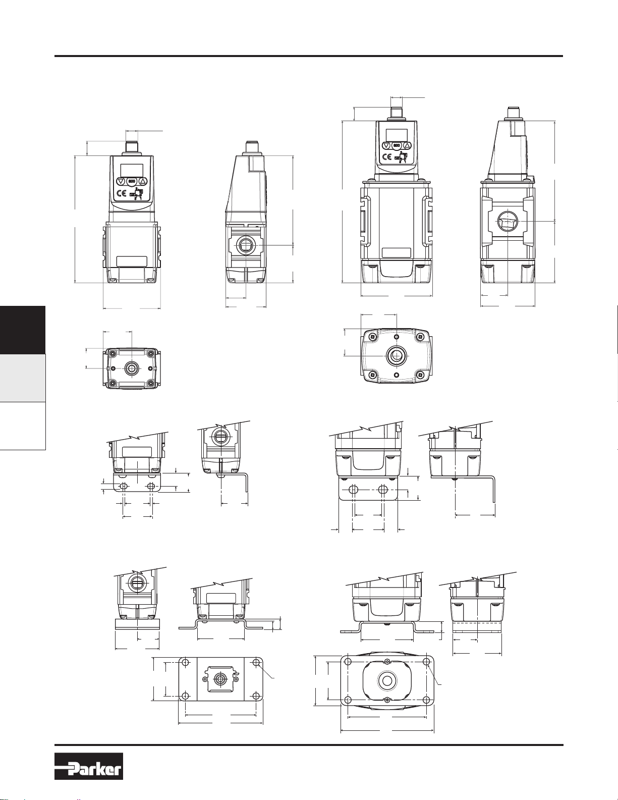
Dimensions
P31P / P32P Series
Electronic Proportional Regulators
P31P Bottom Exhaust Version
4 pin M12
Connector
14.3
(0.56)
126.25
(4.99)
57
(2.25)
28.5
F
P31P / P32P PAR15
(0.79)
(1.12)
20
20
(0.79)
40
(1.58)
89
(3.51)
37.25
(1.47)
P32P Bottom Exhaust Version
4 pin M12
Connector
14.3
(0.56)
175.7
(6.94)
75
(2.96)
37.5
(1.48)
28.6
(1.13)
28.6
(1.13)
57.2
(2.26)
105.3
(4.16)
64.4
(2.54)
7
(0.28)
7
(0.28)
Foot Bracket
L-Bracket L-Bracket
25
30
(1.18)
36
(1.42)
(0.28)
7
(0.98)
15
(0.59)
30
(1.18)
15
(0.59)
30
(1.18)
36
(1.42)
15
(0.59)
15
(0.59)
25
(0.98)
Foot Bracket
12
(0.47)
10
(0.39)
Ø 7
(0.28)
4 holes
52
(2.05)
40
(1.57)
56
(2.20)
12
(0.47)
52
(2.05)
26
(1.02)
52
(2.05)
40
(1.57)
56
(2.20)
Ø 7
(0.28)
4 holes
26
(1.02)
45
(1.77)
(2.05)
52
Dimensions are in mm (Inches)
84
(3.31)
100
(3.94)
F16
www.comoso.comwww.comoso.com
84
(3.31)
100
(3.94)
Parker Hannifin Corporation
Pneumatic Division
Richland, Michigan
www.parker.com/pneumatics
Page 15
Catalog 0700P-E
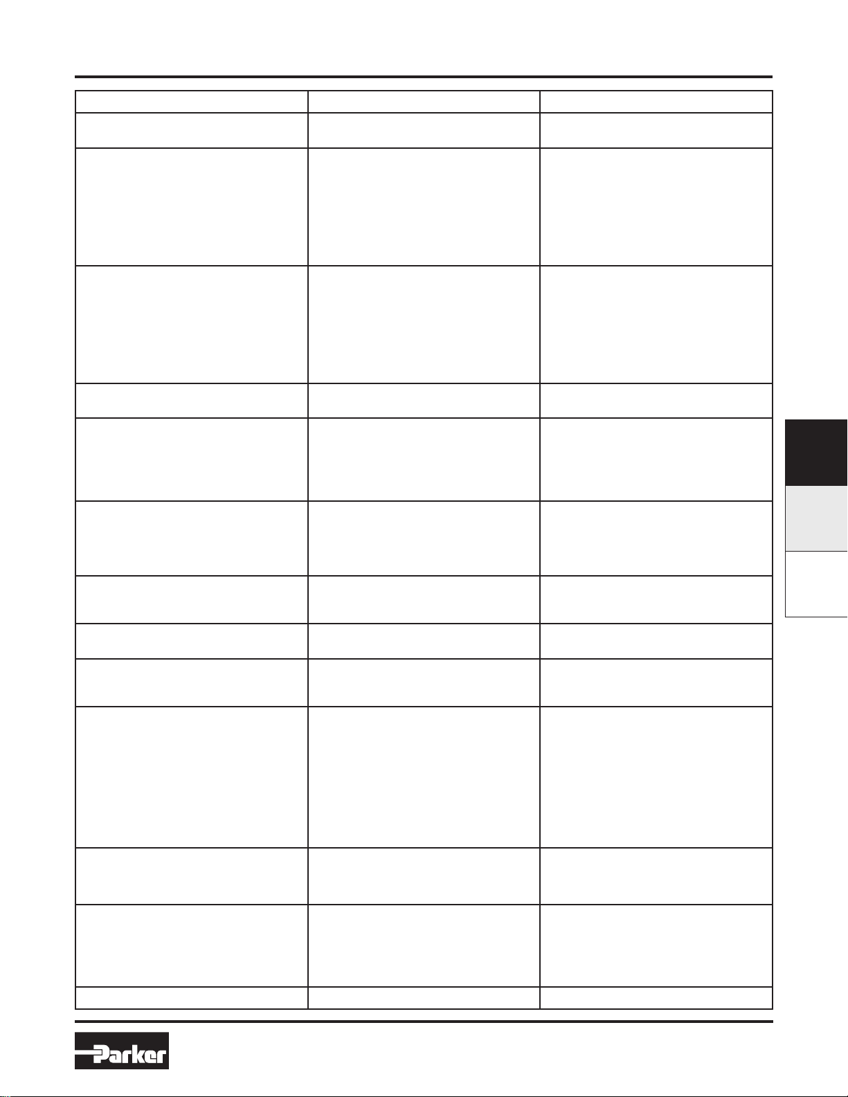
Troubleshooting Guide
P31P / P32P Series
Electronic Proportional Regulators
Problem Possible Reason Solution
Display will not light up No 24 volts power supply Check if the wiring is connected according to
Unit will not, or not correctly respond to
given setpoint
Display shows NoP. Unit detects that required output pressure is
Unit behavior is not considered normal Faulty settings made in the parameters Reset the unit to factory settings by using the
Desired pressure can not be reached Setpoint value to low
Wrong current applied ( I.e. Volt instead of
mA or mA instead of Volt
Setpoint signal is not stable enough Stabilize setpoint signal input
higher than the supplied pressure
No inlet pressure at all Connect port 1 to the supply pressure
the schematic wiring diagram
Change setpoint current or re configure the
setpoint current through the software by
changing parameter 4
Check wiring if the setpoint signal lead is
connected to the right pin within the male
M12 connector ( should be pin 2)
Adjust the inlet pressure to a higher value,
preferably 0,5 bar higher than requested
output pressure
Give lower setpoint value which corresponds
to a output pressure lower than the inlet
pressure
green key function under parameter 0
Increase setpoint value
Pre-set pressure limit has been changed to a
lower max. outlet pressure
Supply pressure is to low Increase supply pressure
Secondary side stays pressurized Setpoint value is higher than 0,1 Volt
Pre-set pressure has been enabled to a
certain pressure
Display shows unrealistic value Display maybe configured in the wrong value
( bar instead of psi)
Unit response time too slow or too quick Volume behind the unit is either too big or
too small
Unit gives too much overshoot Relation between volume and response me
is out of balance
Unit is adjusting/regulating constantly Air leakage in the system behind the unit
Constant changing volume behind the unit
“Deadband “area is set too small
Can not enter software through touchpad Unit is currently working/processing Make sure that the unit is in steady state
Activating time is too short Hold the accept button for at least 3 seconds
Display indicates ‘OL’ Wiring not according to diagram (24 volt con-
nected on the setpoint connection pin)
Wrong setpoint value given in relation to
programmed setpoint value acceptance
Any other problem Please consult factory
F17
www.comoso.comwww.comoso.com
Change max. outlet pressure back to required pressure by changing parameter 19
Lower your setpoint value, preferably to 0
Volts
Reset parameter 18 to 0
Check through parameter 14, if the display
value is set on either psi or bar, if necessary
change it to the required setting
Adjust the regulating speed of the unit
through parameter 20
Adjust response time to a higher value
through parameter 20, to achieve more accurate behavior
Resolve leakage
Unit needs to regulate to keep required pres-
sure at the same level
Try to minimize the volume changes
Enlarge deadband setting through parameter
13 in the software ( parameter 20 has to be
set to 0 before changing parameter 13)
while activating the software
Rewire so that on the setpoint connection pin
will be either 0-10v or 4-20mA
Change over setpoint value to either V or mA
or Reprogram the unit to the correct setpoint
value via parameter 4
Parker Hannifin Corporation
Pneumatic Division
Richland, Michigan
www.parker.com/pneumatics
F
P31P / P23PPAR15
Page 16
Catalog 0700P-E
Glossary
Glossary
Hysteresis – The mechanical limits of accuracy of
the unit. The regulator cannot be adjusted within the
inherent mechanical limits of the design.
Dead Band – The minimum limit of accuracy at which
the regulator is set for normal operation. This band
must be equal to, or exceed, the inherent design limits
of the regulator or the hysteresis band.
Proportional Band – The band used for setting
reaction sensitivity of the regulator. The regulator
senses the excursion from the set pressure and adjusts
response in relation to the degree of excursion beyond
the dead band. This band must exceed the dead band
of the unit.
Proportional Effect – The speed at which the unit
approaches P2 (secondary pressure).
F
P31P / P32P Series
Electronic Proportional Regulators
P31P / P32P PAR15
Sensitivity –
or feedback signal, to cause a change in regulated
output pressure.
Repeatability –
the unit can reproduce an output pressure in relation
to a specific set pressure.
Linearity –
of output pressure vs. the control signal deviates from
a straight line function.
PNP Output –
collector transistor output where the voltage sources
towards 24VDC when activated.
NPN Output –
collector transistor output. The output sinks towards
0VDC when activated.
The smallest change in the control signal,
a measurement of how consistently
A measure of how closely the relationship
Referred to as a “Sourcing” open
Referred to as a “Sinking” open
F18
www.comoso.comwww.comoso.com
Parker Hannifin Corporation
Pneumatic Division
Richland, Michigan
www.parker.com/pneumatics
 Loading...