

Page 1
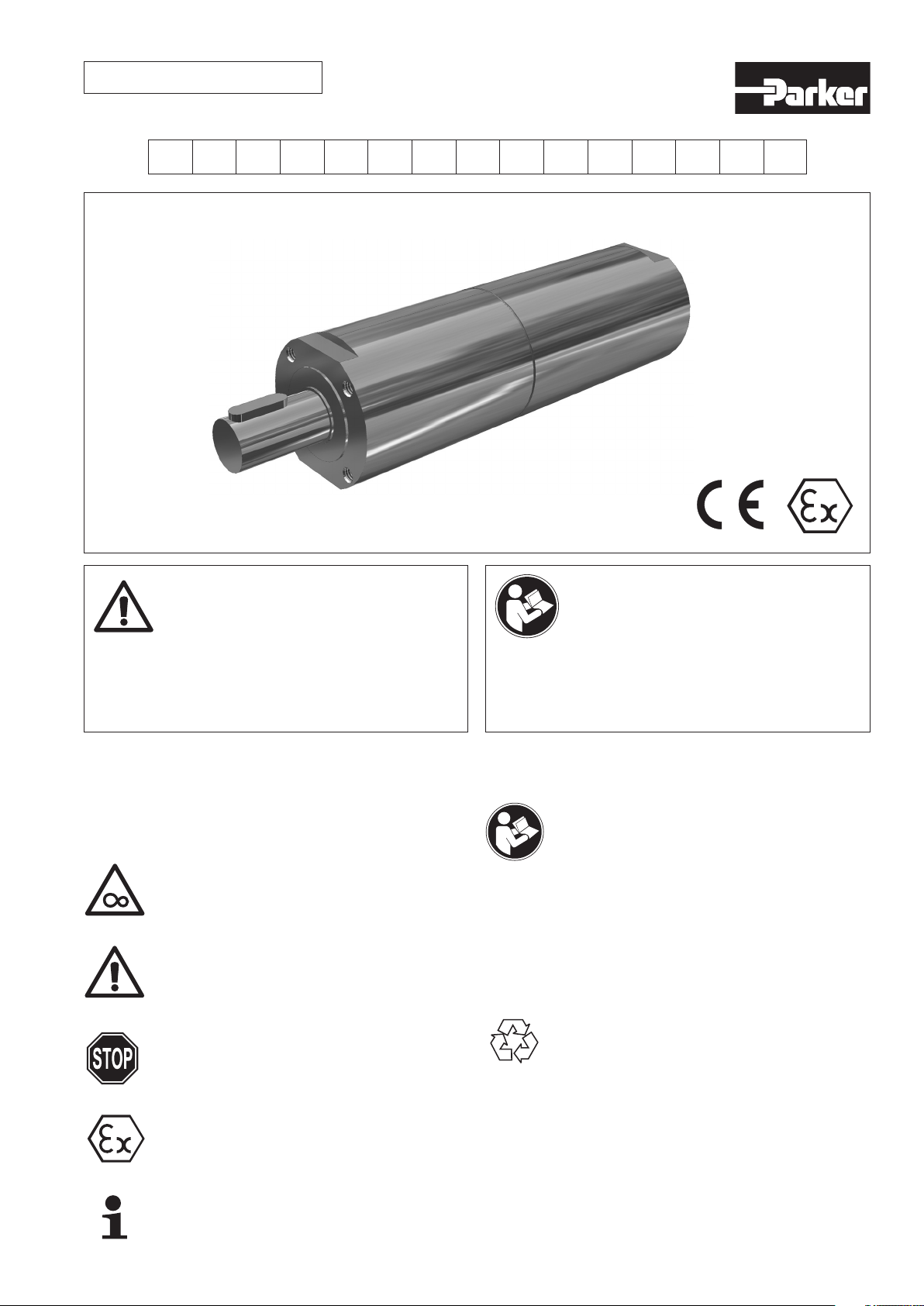
4601503-P1V-S Issue 5
Disconnect air and electrical supplies before
attempting repair or maintenance.
See ISO 4414-1982 for safety requirements covering
the installation and use of pneumatic equipment.
Koppla ifrån luft och elektriska anslutningar innan
reparations-och underhållsarbeten påbörjas.
Se ISO 4414-1982 för säkerhetsbestämmelser
täckande installation och användning av pneumatisk
utrustning.
1. Important Notes
Safety and Warning Signs
The safety and warning instructions contained
should always be followed!
IMMEDIATE DANGER
Possible consequences: death or grave injuries.
DANGEROUS SITUATION
Possible consequences: slight or minor injuries.
DAMAGING DANGER
Possible consequences: damage to drive or the
surrounding area.
Important instructions relating to explosion
protection.
Application tips and other useful information.
NOTICE ALL DOCUMENTATION!
Before beginning work this operating instruction
booklet has to be read through carefully. Always follow
the instructions during operation. Give this operating
instruction booklet to the operator.
Definition
Potentially explosive atmosphere (hereinafter referred to as
“Ex-area”)
= An atmosphere which could become explosive due to
local and operational conditions.
The observance of the operating instructions is the
precondition for an error free operation and the fulfillment
of warranty claims. Therefore, please read the operating
instruction booklet prior to working with the air motor!
The operating instruction booklet contains important tips
for motor service and should therefore be kept in the
vicinity of the motor.
Disposal
Always observe the most current regulations for
disposal.
Especially during installation, repair or maintenance water
damaging agents, such as:
• lubricating greases and oil
• hydraulic fluid
• cooling agents
• solvent-containing cleaning agents may not leak into
the ground or into the sewage system!
Such materials must be stored, transported, contained
and recycled in suitable containers.
Housing parts, tooth rings, shafts, as well as gear parts
should be disposed off as steel scrap.
Page 2
2. Safety Instructions
2.1 General Safety Instructions for Standard
Operation (non-explosive area)
Introduction
Prior to operating the motor, make sure to carefully
read this operating instruction booklet (short OP).
Please pay attention to the additional safety
instructions in the individual chapters of this OP.
The air motor or its load may have hot surfaces, during
and after operation.
Assembly / installation, connection, operation as well as
maintenance and repair work may only be performed by
Parker or qualified persons / technical experts
Injury and damage to property may occur due to
inaccurate installation and operation or
non-designated use of motor.
Dealing with Compressed Air
• Always wear safety goggles.
• Do not move into the stream of compressed air.
• Do not use the motor with other gases or liquids.
• Do not operate the motor at higher pressure than
specified.
Intended Use
This air motor is mainly used to generate a rotating
motion in industrial equipment.
Basically, the air motor is approved for the use in the food
industry. For the particular application the operator must
comply with the valid legal requirements.
The motors’ technical data, as well as
pertinent conditions for its use, can be found in this OP.
Deviations from these requirements are not allowed!
2.2 Owner Obligation
2.4 Warranty and Liability
Unless otherwise specified, our “General Sales and Delivery Conditions”
apply. Warranty and liability claims in regards to persons or equipment
damage are invalid if one or several of the following causes apply:
• Use of the equipment in a non-designated application.
• Improper installation, operation, service or maintenance of the
machine.
• Operation of the machine with either defective or removed safety and
protection devices.
• Non-observance of the requirements stated in the operating
instruction booklet, in regards to transportation, storage, mounting,
installation, operation, maintenance and service of the equipment.
• Structural change or adjustment on the equipment to a
non-designated use.
• Inadequate supervision of wear parts.
• Improper repair, inspection or maintenance.
• Catastrophic cases due to war, acts of God or other events beyond
our control.
2.5 Additional Safety Instructions for Use of Motor
in Explosive Area
Explosive gas or dust atmospheres may cause grave
or fatal injuries when coming in to contact with hot
or movable parts in the air motor.
Assembly / installation, connection, operation as well as
maintenance and repair work may only be performed by
Parker or qualified persons / technical experts and if the
following items are observed:
• read OP
• all warning and alert messages attached to the air motor
• all other or the operation pertinent documentation, such
as project documents, operating instructions and
control diagrams
• all machine specific regulations and requirements
• the most current and valid national/regional regulations
(explosion protection, safety, accident prevention)
The owner is obliged to only let persons operate the equipment, who:
• are familiar with basic work environment safety rules and accident preventing regulations. Also, those persons must have been
instructed in the correct use of the equipment.
• have read and understood all safety and warning notifications in
the operating instruction booklet, as well as all other documentation
pertaining to this equipment.
• check and confirm at regular intervals, that a safety oriented operation
is guaranteed.
Only qualified and authorised personnel are allowed to operate,
maintain and repair this equipment. A malfunction, which impairs
operator safety, must be immediately removed.
2.3 Operator Obligation
Personnel, who are engaged in the operation of the equipment, must
always be committed to:
• observe the basic safety and accident preventing regulations.
• read and observe the safety and warning notifications of this
operating instruction booklet.
Intended Use
This air motor is used to generate a rotating motion in
industrial equipment and it needs to be operated in
accordance with the instructions of the technical
documentation, while observing the information
inscribed on the tag. It corresponds to all valid standards
and regulations and fulfills the requirements per guideline
2014/34/EU (ATEX).
It is not permissible to use this air motor as a
braking motor.
The air motor may not be used underground by mines
or any of their distribution stations, where pit gas and/
or other flammable dusts occur. It may be used in areas
where occasionally explosive atmospheres occur, which
may be a combination of air and gas, or steam and fog of
a flammable fluid or dust/air mixture (Zone 1 and Zone 21).
Air motors without an engraved -Symbol are not
designed for the use in Ex-areas (see chapter 4.4)
3. Delivery Capacity
Check that the shipment is complete and that there have been no
damages in transit.
Quantity Name Order No.
1 Operating Instruction Booklet
1 Pneumatic Air Motor P1V-S...
2
www.parker.com/euro_pneumatic
Page 3
4. Structure
4.4 Nomenclature
4.1 Basic Design Criteria for Air-Operated Gear
Motors
(planetary) gearing air-operated vane motor
4.2 Maximum Allowable Shaft Load on the Drive
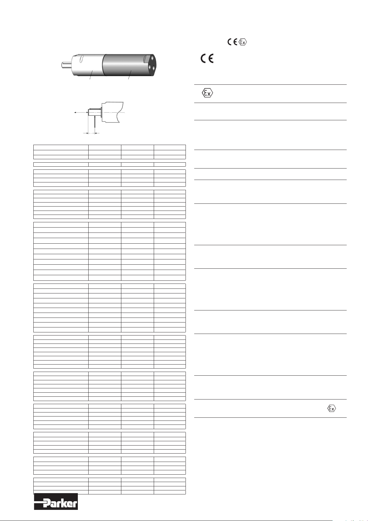
Shaft
F
ax
F
rad
a
Illustration 1 - Axial and radial force on parallel key shaft
Order code Fax [N] Frad [N] a [mm]
P1V-S002A0130 140 180 6
P1V-S002A0095 140 180 6
P1V-S003B0100 140 180 6
P1V-S008A0Q00 200 220 7
P1V-S008A0700 200 220 7
P1V-S008A0190 200 220 7
P1V-S008A0130 200 220 7
P1V-S012A0N00 380 160 9
P1V-S012A0550 380 160 9
P1V-S012A0360 380 160 9
P1V-S012A0140 380 160 9
P1V-S012A0090 380 160 9
P1V-S012A0060 380 160 9
P1V-S012A0010 380 160 9
P1V-S020A0E50 570 720 12
P1V-S020A0460 570 720 12
P1V-S020A0240 570 720 12
P1V-S020A0140 570 720 12
P1V-S020A0070 570 720 12
P1V-S020A0032 570 720 12
P1V-S020A0018 570 720 12
P1V-S020A0005 570 720 12
P1V-S020A0002 570 720 12
P1V-S020A0001 570 720 12
P1V-S020A00005 570 720 12
P1V-S030A0E50 570 1130 14
P1V-S030A0460 570 1130 14
P1V-S030A0240 570 1130 14
P1V-S030A0140 570 1130 14
P1V-S030A0060 790 1070 15
P1V-S030A0034 790 1070 15
P1V-S030A0023 790 1070 15
P1V-S030A0018 790 1070 15
P1V-S030A0010 790 1070 15
P1V-S030A0005 790 1070 15
P1V-S060A0E00 1110 1300 15
P1V-S060A0350 1110 1300 15
P1V-S060A0270 1110 1300 15
P1V-S060A0170 1110 1300 15
P1V-S060A0063 1110 1300 15
P1V-S060A0048 1130 2090 18
P1V-S060A0030 1130 2090 18
P1V-S060A0015 1130 2090 18
P1V-S090A0C00 1110 1300 15
P1V-S090A0350 1110 1300 15
P1V-S090A0270 1110 1300 15
P1V-S090A0170 1110 1300 15
P1V-S090A0063 1110 1300 15
P1V-S090A0048 1130 2090 18
P1V-S090A0030 1130 2090 18
P1V-S120A0900 2330 2260 18
P1V-S120A0250 2330 2260 18
P1V-S120A0110 2330 2260 18
P1V-S120A0070 2330 2700 30
P1V-S120A0032 2330 2700 30
P1V-S120A0020 2330 2700 30
P1V-S028A0017 1500 3500 21
P1V-S028A0008 1500 3500 21
P1V-S028A0005 1500 3500 21
P1V-S028A0003 1500 3500 20
P1V-S028A0002 1500 3500 20
P1V-S057A0015 1500 3500 21
P1V-S057A0011 1500 3500 21
P1V-S057A0007 1500 3500 21
P1V-S057A0004 1500 3500 22.5
P1V-S086A0015 1500 3500 21
P1V-S086A0011 1500 3500 21
P1V-S086A0007 1500 3500 21
P1V-S086A0004 1500 3500 22.5
Fax = axial force
F
= radial force
rad
Example:
II
2
GD
c
IIC
T6
(80°C)
T5
(95°C)
T4
(130°C)
X
II 2 GD c IIC T4 (135oC) X
Communauté Européenne = European Community
This symbol documents the declaration of the
manufacturer that the required EC-guidelines – as stated
in the EC-Declaration of Conformity - are observed and its
provisions are followed.
This air motor is suited for standard use in
Ex-areas.
Design Group: this motor is NOT designed for use in
underground mining.
Design Category: this motor is designed for the use in
areas where occasionally explosive atmospheres may
exist, which consist of gases, steam, combustible fumes
or a combination of dust and air (Zone 1 and Zone 21).
This motor is suited for the use in Ex areas, which are
caused by combustible gases, steams, fumes or dust.
Ignition Protection: structural protection
Explosion Group: This motor is suited for the requirements
per Explosion Group IIC. It also fulfills the requirements of
the Explosion Groups IIB and IIA.
Temperature Class:
T6 = 85°C surface temperature
A motor with a temperature class of T6 may not exceed a
maximum surface temperature of 85°C. Motor should be
tested to ensure that the permissible temperature does not
exceed 80°C; there is a safety margin of 5°C.
This is the maximum permissible surface temperature of
the motor if used in an explosive atmosphere containing
dust.
Temperature Class:
T5 = 100°C surface temperature
A motor with a temperature class of T5 may not exceed a
maximum surface temperature of 100°C. Motor should be
tested to ensure that the permissible temperature does not
exceed 95°C; there is a safety margin of 5°C.
This is the maximum permissible surface temperature of
the motor if used in an explosive atmosphere containing
dust.
Temperature Class:
T4 = 135°C surface temperature
A motor with a temperature class of T4 may not exceed a
maximum surface temperature of 135°C. Motor should be
tested to ensure that the permissible temperature does not
exceed 130°C; there is a safety margin of 5°C.
This is the maximum permissible surface temperature of
the motor if used in an explosive atmosphere containing
dust.
„Observe special requirements“ In the Operating
Instruction Booklet marked with the symbol
3
www.parker.com/euro_pneumatic
Page 4
5. Assembly Instructions
Perform all assembly, installation, maintenance and
repair work outside of the Ex-area.
5.1 Prior to Installation
The air motor should only be installed if:
• the details of the motor tag correspond with the details
of the potentially explosive athmosphere of use (design
group, design category, Ex-area, temperature class,
maximum surface temperature).
• it is undamaged.
• it was verified that no explosive atmospheres, oils,
acids, gases, steams or radiation, occurred during
installation.
5.2 Pre-Installation
Drive shafts and flange areas should always be free from
anticorrosive solvents, dirt or other agents. Solvents
should not be allowed to penetrate the gear seal ring –
this may cause material damage!
To avoid a swelling of the seal rings and damage to
internal parts of the air motor, use only solvents approved
by Parker (such as HAKU 1025-810-1 cold cleaner). Seal
material: NBR/FKM
5.3 Operating Pressure and Temperature Range
Operating Pressure
Maximum operating pressure: 6 bar / 85 PSI
Temperature Range
Ambient temperature at standard operating
(outside Ex-area): -20°C to +110°C
Ambient temperature for use in Ex-area: -20 °C to + 40 °C
Compressed Air Temperature
The temperature of the compressed air used may not
exceed the ambient temperature requirements.
If ambient temperatures are different, please contact
Parker.
5.4 Installation Instructions
Important Notes for Installation of Motor
• Install the motor according to the dimension sheet
(see chapter 5.6).
• The air motor may be installed in any orientation.
• Non-reversible air motors have a right or left rotational
direction (as seen from air inlet in the direction to the
drive.
• Use only mounting brackets having a sufficient size.
• Use only the implemented mounting holes to fixture the
air motor.
• Observe the tightening torques for the mounting screws
(see table 1).
• A maintenance unit should be installed
(see illustration „Diagram“ in chapter 5.7).
• Be especially careful with all rotating parts.
• Do not install a belt pulley, clutch or pinion to the
shaft-end, using ham-mer blows; this will damage
gears, housing and shaft.
• Use an extractor for disassembly.
• Do not exceed the permissible radial and axial forces of
the shaft (see chapter 4.2).
Attachment of the drive element will be simplified if a
lubricant is applied or when heated-up for a moment –
prior to installation (to 80°C to 100°C).
Drive attachments, such as a belt pulley, clutch, etc. have
to be covered by a contact guard.
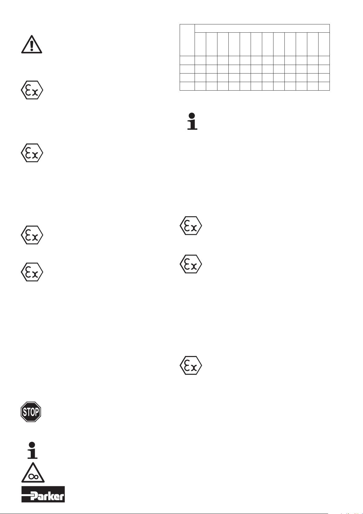
Tightening torque (Nm) for thread ...
Property
Class
M 2.5
M 3
M 4
M 5
M 6
M 8
M 10
M 12
M 14
M 16
M 18
M 20
8.8 0.72 1.28 2.9 5.75 9.9 24 48 83 132 200 275 390
10.9 1.02 1.8 4.1 8.1 14 34 67 117 185 285 390 550
12.9 1.21 2.15 4.95 9.7 16.5 40 81 140 220 340 470 660
70* 0.46 0.82 1.9 3.7 6.4 15.3 31 52 83 126 174 245
* for stainless screws
Table 1 – Tightening torques for mounting screws
Use screws of property class (min.) 8.8 or 70 for stainless
screws in order to mount the air motor onto your machine.
5.5 Additional Instructions for Installation in an
Explosive Hazardous Area
Always follow the safety instructions of chapter 2.5 while installing an air
motor into an Ex-area.
Grounding
The air motor must be grounded, for example by using
• an air-supply line made of metal or
• an electrically conductive hose.
The resistance between motor and ground has to be
measured (requirement: <106 Ω).
Only use drive attachments that correspond to guideline 2014/34/EU. Only use belts in the Ex-area, which
correspond to the guideline 2014/34/EU (among others,
items to watch is the belts electric conductivity and the
correct belt-tension, since either may generate heat due
to slippage).
The explosion-proof air motors correspond to the design
requirements of the design group II, category 2 GD (explosive atmosphere consisting of gas and dust).
Those motors are suited for the installation into Zone 1
and Zone 21.
Temperature Class
The air motors of group II, category 2 GD are suitable for
the temperature class: T6, TS ov T4
Surface Temperature
This corresponds to a maximum surface temperature of:
80, 95 ov 130 °C
Protection Class
All air motors must correspond – for a minimum – with the
standard EN 60529 of the protection class IP 54. They are
designed for the use in dusty or damp environments.
Ambient Conditions
Make sure that the air motor is sufficiently ventilated and
that there is no additional warming source (such as a
clutch).
Open inlet and exhaust ports are not permissible. Those
type of ports have to be closed, using either a sinteredmetal filter (optional equipment) or an airline. If an airline
is installed to any of the open ports (without the use of a
sintered-metal filter), then they have to be guided out of
the Ex-area.
Drive Power and Torque
Do not exceed either the maximum permissible drive
power, or the maximum allowable radial and axial forces.
Braking Mode
The air motors may not be used in a braking mode in
the Ex-area. A braking mode is when the motor is
operated opposite to the turn-direction of the air-supply;
this will have the motor operate as a compressor.
4
www.parker.com/euro_pneumatic
Page 5
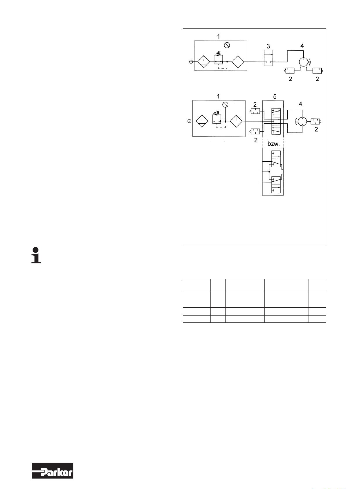
5.6 Dimensions
Please refer to the technical catalogue PDE2554TC
5.7 Installation
Prior to Connection of Motor
Before connecting the air supply line to the motor, clean
the air pipe and the air hose by slightly blowing air into
the pipe/hose. This will remove any dirt particles that are
present in the pipe/hose.
Always wear safety goggles, tightly hold the pipe/
hose and do not move into the air stream.
Remove the covers from the connections.
Turn the air-supply to “OFF”.
Air Supply Line
Make sure, that all air lines have a sufficient cross-section
(see chapter Technical Data) and that there are no throttle
areas, bends or kinks. If the air supply line is longer than
2 meters, the next larger hose I.D. should be installed in
order to avoid a loss of power.
Connection of Motor
For operation in only one turn-direction:
See Diagram, figure a)
Install silencers (optional equipment) into the unused ports.
For reversible operation
(clockwise and anticlockwise direction):
See diagram, figure b)
Connect 2 supply lines to the motor. For position and size
of the air inlet ports, see Dimensional Drawing
(chapter 5.6).
Do not close unused ports with a plug or the like. This may
lead to a loss of the motor’s power or motor standstill. The
exhaust air may be piped away using either an exhaust line
or a silencer as well.
Do not use any Teflon tape on the threads of the pipe.
Operating Pressure
Check and make sure that the flow-pressure at the motor
connection side is 6 bar (85 PSI). A higher air pressure
leads to increased wear and tear (install a pressure
regulator). An air pressure below 6 bar reduces the power
output of the motor.
Lubrication
All motors may be operated either with or without
lubricated air. The best performance is achieved by adding
1 – 2 drops of oil per 1 m³ of air consumption. When
operating with oil-free air, a performance reduction of up
to 20% occurs.
The air supply to the motor has to be filtered (see chapter
5.8).
The maintenance unit, the valves and the silencers have
to be selected according to the air consumption of the
motor, not in accordance to the connection threads. Install
components, which have a measurement that will limit the
pressure drop – when measured from the maintenance
unit to the motor – to less than 0.5 bar (7.25 PSI).
Install a maintenance unit, fill it with oil and adjust oiler as
needed. Fill the oil container of the oiler to the indicated oil
level.
a)
b)
1. Maintenance unit (filter with water separator, pressure regulator
and oiler)
2. Silencer
3. 2/2-way-valve
4. Motor
5. 5/3-way-valve or alternatively 2 x 3/2-way-valve
Illustration 2 - Diagram
5.8 Air Quality
With regard to air quality according to ISO 8573-1 we recommend:
Class Residual Dust Residual Water Residual
Oil
particle max. max. pressure content
size um concentrati concentrati dew-point mg/m
on mg/m3 on mg/m3 °C
Lubricator air -/4/4 25 10 5 +3 5
Oil-free air 6/3/3 5 5 1 -20 1
* Filter grade 8 µm is sufficient for units machines that are operated in
dry run.
3
Lubricants
Use only lubricants approved by the manufacturer.
5
www.parker.com/euro_pneumatic
Page 6
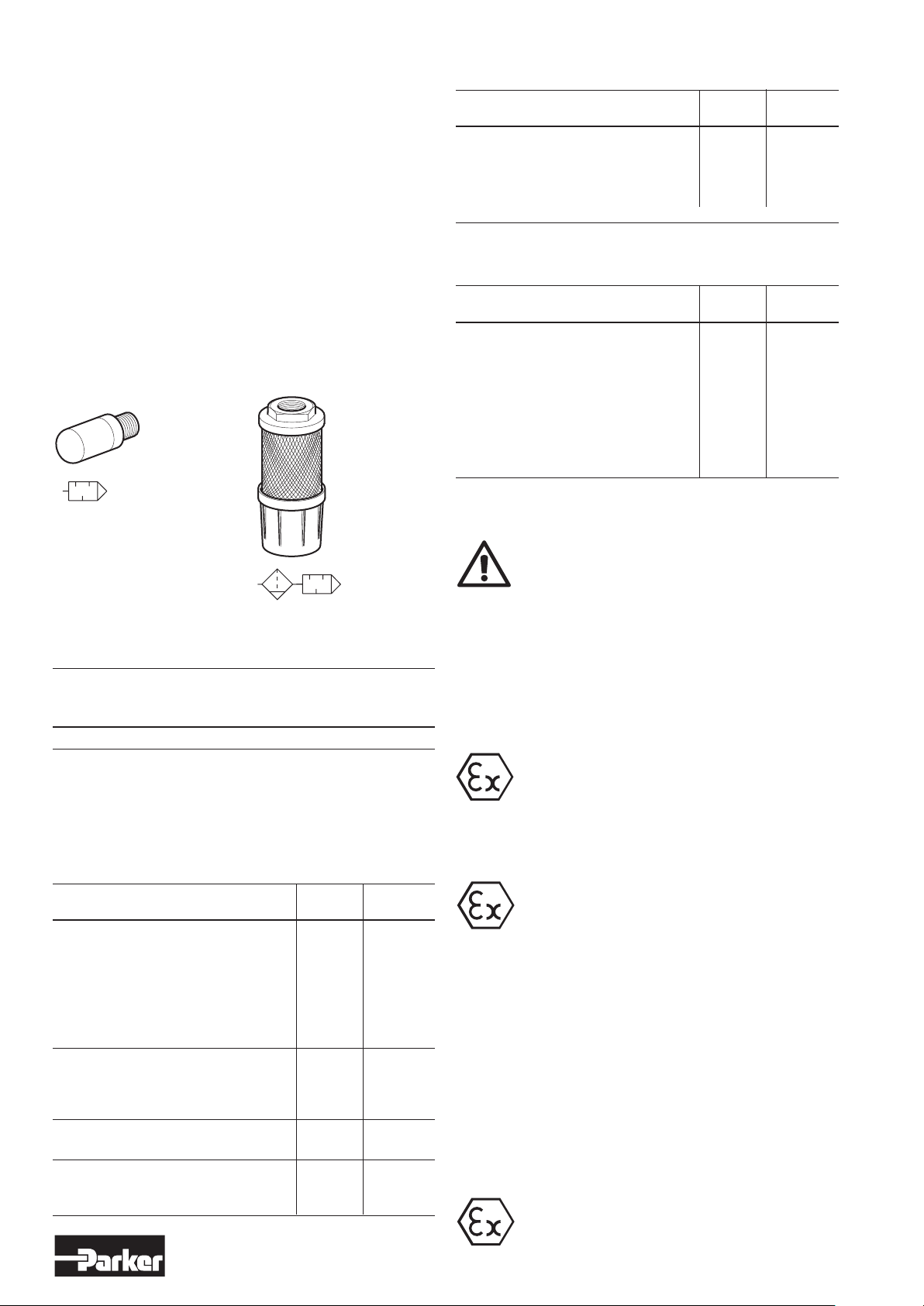
5.9 Silencing
The noise from an air motor consists of both mechanical noise and a
pulsating noise from the air flowing out of the outlet. The installation of
the motor has a considerable effect on mechanical noise. It should be
installed so that no mechanical resonance effects occur. The outlet air
creates a noise level which can amount to 108 dB(A) if the air is allowed
to exhaust freely into the atmosphere. To reduce noise levels, various
types of outlet silencer are used. The most common type screws
directly into the outlet port of the motor. A wide range of silencers are
available. Many are made of sintered brass or sintered plastic. Since the
motor function causes the exhaust air to pulsate, it is a good idea to
allow the air to exhaust into some kind of chamber first, which reduces
the pulsations before they reach the silencer. The best silencing method
is to connect a soft hose to a central silencer allowing the speed of the
air to reduce as much as possible.
NOTE! Remember that if a silencer is too small or is blocked, back
pressure is generated on the outlet side of the motor, which in turn
reduces the motor power.
Outlet silencer
Central silencer
Test prior to use of motor in EX-area Checked Reference
Chapter
Is a formal EC-Declaration of Conformity in
accordance with guideline 2014/34/EU available
5.5
for all components that will be at-tached to
the air motor?
This check list shows all activities, which have to be performed during
the use of the air motor in an Ex-area (according to the guideline
2014/34/EU – previously ATEX 100a).
Test during use of motor in Ex-area Checked Reference
Chapter
After approximately 1.5 hours of operation,
measure the surface temperature.
A temperature increase of over 40K is not 6.3
allowed.
Example:
Tmax = TU + rT = 20°C + 40K = 60°C
If a temperature increase >40K occurs
immediately stop the drive and contact
Parker!
6.2 Motor Operation
Sound levels
Sound levels are measured at free speed with the measuring instrument
positioned 1 m away from the air motor, see the table below
Air Free outlet With outlet Exhaust air removed
motor silencer with pipes to
another room
dB (A) dB (A) dB (A)
Please refer to the technical catalogue PDE2554TC
6. Operation
6.1 Check List
This check list shows all activities, which have to be performed prior
to the use of the air motor in an Ex-area (according to the guideline
2014/34/EU – previously ATEX 100a).
Test prior to use of motor in EX-area Checked Reference
Chapter
Do the following specifications of the tag on
the air motor agree with the required
specifications of the Ex-area: 4.3
• design group 4.4
• design category
• Ex-area
• temperature class
• maximum surface temperature
Has it been confirmed that during the
installation of the air motor there were no 5.1
explosive atmospheres, such as oils, acid,
gas, steam or radiation?
Is the ambient temperature in accordance 5.3
with requirements?
Has it been certified that the air motor is
sufficiently ventilated and that there is no 5.5
additional warming source (such as a clutch)?
I
6.3 Measure Surface Temperature
(if motor is used in an explosive area)
Make sure that all air supply parts are correctly
connected, prior to motor operation.
Do not step into the air stream
Turn the air-supply to “ON”.
If necessary, adjust the air-pressure or the flow-pressure to
achieve the required speed or torque.
Adjust the oiler as described in chapter 5.7 – paragraph
„Lubrication“.
Regularly check the oil-level and if necessary refill the oil
container.
The motor needs to be cleaned on a regular basis to avoid
a dust deposit with a more than 5-mm thickness.
The details of the maximum allowable surface
temperature as shown on the motor tag are based
on measurements under normal environmental and
installation conditions. Small changes to those
conditions (such as a constructed installation area)
will considerably effect the temperature
development!
Measure Surface Temperature
It is very important to measure the surface temperature of
the motor during operation. Measurement can be done
using conventional temperature measuring instruments.
The surface temperature should be taken at the marked
measuring point as specified on the dimensions (see
chapter 5.6).
The maximum allowable surface temperature is reached
after approximately 1.5 hours of operation. This maximum
temperature must not increase more than 40K.
Ambient temperature in the Ex-area: -20°C to +40°C
If the surface temperature exceeds the mandate, the
motor must be stopped immediately.
Please immediately contact Parker!
6
www.parker.com/euro_pneumatic
Page 7
7. Maintenance and Upkeep
8. Disassembly – Assembly
The first maintenance should be performed after 500 operating
hours with non-lubricated air and after 1,000 operating hours
with lubricated air. Thereafter, we recommend adjusting the
maintenance intervals to the general usage and wear condition
of the motor as well as the application area.
Lubrication
If the air motor is sufficiently lubricated, it requires little
maintenance. The air motor should be regularly checked
in regards to excessive noise and/or if the gears show an
increased play.
The planetary gears and the bearings have to be
sufficiently greased (see chapter 8.3 “Assembly”).
After every maintenance session, the planetary gears have
to be cleaned and re-greased.
Clean filter of the maintenance unit and bleed water
condensation. If necessary, replace the filter to protect
the motor against blockage caused by dirt particles in the
supply air.
Regularly check the oil-level in the oiler and refill oiler as
needed.
Lubricants
Use only lubricants approved by the manufacturer.
Bearing Exchange
To assure a continued low surface temperature if motor is
used in an Ex-area, observe the following:
• Replace the bearings in the gearing after 10-Million
rotations.
• Replace the bearings in the motor after 8,000 operating
hours.
Worn Vanes
Our experience has shown that the vanes (in a complete
set) have to be replaced latest after 2,000 operating hours.
This interval may be longer or shorter, depending on the air
quality and application area.
Loss of Power
If the motor does not operate correctly, after being used
for a long time, then the flats of the vanes have been
clogged in the rotor-slots by the oils resin residue. In such
cases, it is necessary to clean the motor.
Seal Rings
The failure of a seal ring causes the grease in the gearing
to prematurely dry out. Replace any brittle or damaged
seal ring immediately.
If the motor is maintained on a regular basis, then the wear
and tear on the movable parts is minimal. The wear mainly
depends on the operating speed, the air pressure and the
lubrication. We recommend sending a failed air motor to
us for repair. We have all the necessary special repair tools
for the disassembly, original spare parts and the trained
repair specialists that can adjust the air motor to the
correct gap play. The gap play determines the motors
power, efficiency and life expectancy.
7.1 Wear Parts
Quantity Description Order code
Please refer to the technical catalogue PDE2554TC
( Ô Spare Part Drawing/s)
Disassembly and assembly of the air motor may
only be performed by Parker or qualified persons /
technical experts.
The air motor may start and cause a hand injury.
Disconnect air motor from the air supply.
After every maintenance session, verify that equipment
runs to the required specifications.
Principally, use only Parker original spare parts. Otherwise,
a reduction of equipment power-output and an increased
maintenance requirement occurs.
If non-Parker parts are installed, then Parker is justified to
avoid any existing warranty and liability obligations.
Only use original Parker service tools in order to avoid
causing damage.
8.1 Service Tools (Optional Equipment)
Name Order code
Fixing device (to clamp the rotor cylinder) On request
8.2 Disassembly
1. Unscrew gear housing from motor housing.
2. Push the motor parts out of the motor housing.
3. Remove support disc and o-ring.
4. Clamp motor on its rotor cylinder into fixing device.
5. Pull off shaft-side bearing cover from rotor.
6. Remove rotor cylinder.
7. Take out the 5 vanes from the rotor.
Basically, replace the vanes.
Exchange only complete sets of vanes.
8. Pull off air-connecting side bearing cover from rotor.
9. Press the two ball bearings from the bearing covers.
8.3 Assembly
Lubrication
• Fill space areas of the planetary gear with 1/3rd of
Parker-grease for the use in the food industry.
• Sufficiently grease the bearings.
• Use only lubricants approved by the manufacturer.
1. Clean rotor.
2. Press the ball bearings into the two bearing covers.
3. Press the shaft-side bearing cover with the ball bearing
on the rotor.
4. Insert 5 new vanes into the rotor.
5. Put the rotor cylinder over the rotor.
After assembly the bearing covers shouldn’t have
any axial gap. The rotor must turn freely.
6. Press air-connecting side bearing cover with ball
bearing on the rotor.
7. Assemble o-ring and support disc.
8. Slide the motor parts (arranged in correct sequence)
into the motor housing.
Bearing needle must engage into the bore of the
motor housing.
9. Tighten motor housing on to gear housing.
7
www.parker.com/euro_pneumatic
Page 8
X
9. Lubrication and service life
The first service is due after approximately 500 hours of operation. After
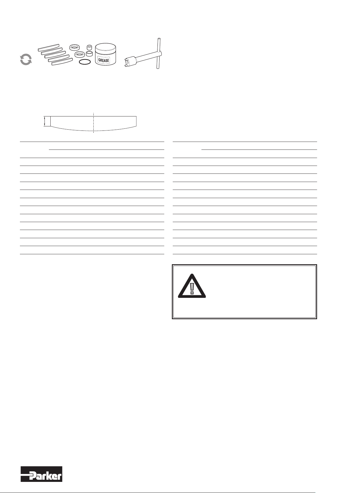
the first service, the service interval is determined by the degree of vane
wear*. The table below shows new dimensions and the minimum
dimensions of worn vanes.
Air motor Dimensions on new vanes X (mm), type of vanes
Standard Z C M
P1V-S002 3.3 - - -
P1V-S003 X - - -
P1V-S008 4.3 - - -
P1V-S012 4.2 4.2 4.2 4.2
P1V-S020 6.5 6.0 6.0 6.0
P1V-S028 X X X X
P1V-S030 6.8 6.2 6.8 6.2
P1V-S057 X X X X
P1V-S060 9.0 9.0 9.0 9.0
P1V-S086 X X X X
P1V-S090 X X X X
P1V-S120 14.7 14.0 14.0 14.0
The following normal service intervals should be applied to in
order to guarantee problem-free operation in air motors working
continuously at load speeds.
Intermittent lubrication-free operation of motors with
standard vanes, option 0
Duty cycle : 70%
Max. duration of intermittent use : 15 minutes
Filtering 40 µm : 750 hours of operation*
Filtering 5 µm : 1,000 hours of operation*
Air motor Dimensions on vanes X (mm), type of vanes
Standard Z C M
P1V-S002 3.0 - - -
P1V-S003 X - - -
P1V-S008 4.0 - - -
P1V-S012 3.3 3.3 3.3 3.3
P1V-S020 5.8 5.3 5.3 5.3
P1V-S028 X X X X
P1V-S030 6.0 5.2 6.0 5.2
P1V-S057 X X X X
P1V-S060 6.0 6.0 6.0 6.0
P1V-S086 X X X X
P1V-S090 X X X X
P1V-S120 14.2 13.5 13.5 13.5
* The specified hours of operation apply when
the motor is running at the speed corresponding
to maximum power (load speed).
This is approximately half free speed.If the motor
operates at higher speeds, the service interval
is shorter.If the motor operates at lower speeds,
the service interval is longer.
Continuous lubricated operation of motors with standard
vanes, option 0
Duty cycle : Continuous
Quantity of oil : 1 drop per m3 of air
Filtering 40 µm : 1,000 hours of operation*
Filtering 5 µm : 2,000 hours of operation*
Note! After 1000 hours of operation, the grease in the planetary
gearbox must be changed
Continuous lubrication-free operation of motors equipped
with vanes, option C
Duty cycle : Continuous
Filtering 40 µm : 750 hours of operation*
Filtering 5 µm : 1,000 hours of operation*
8
www.parker.com/euro_pneumatic
Page 9
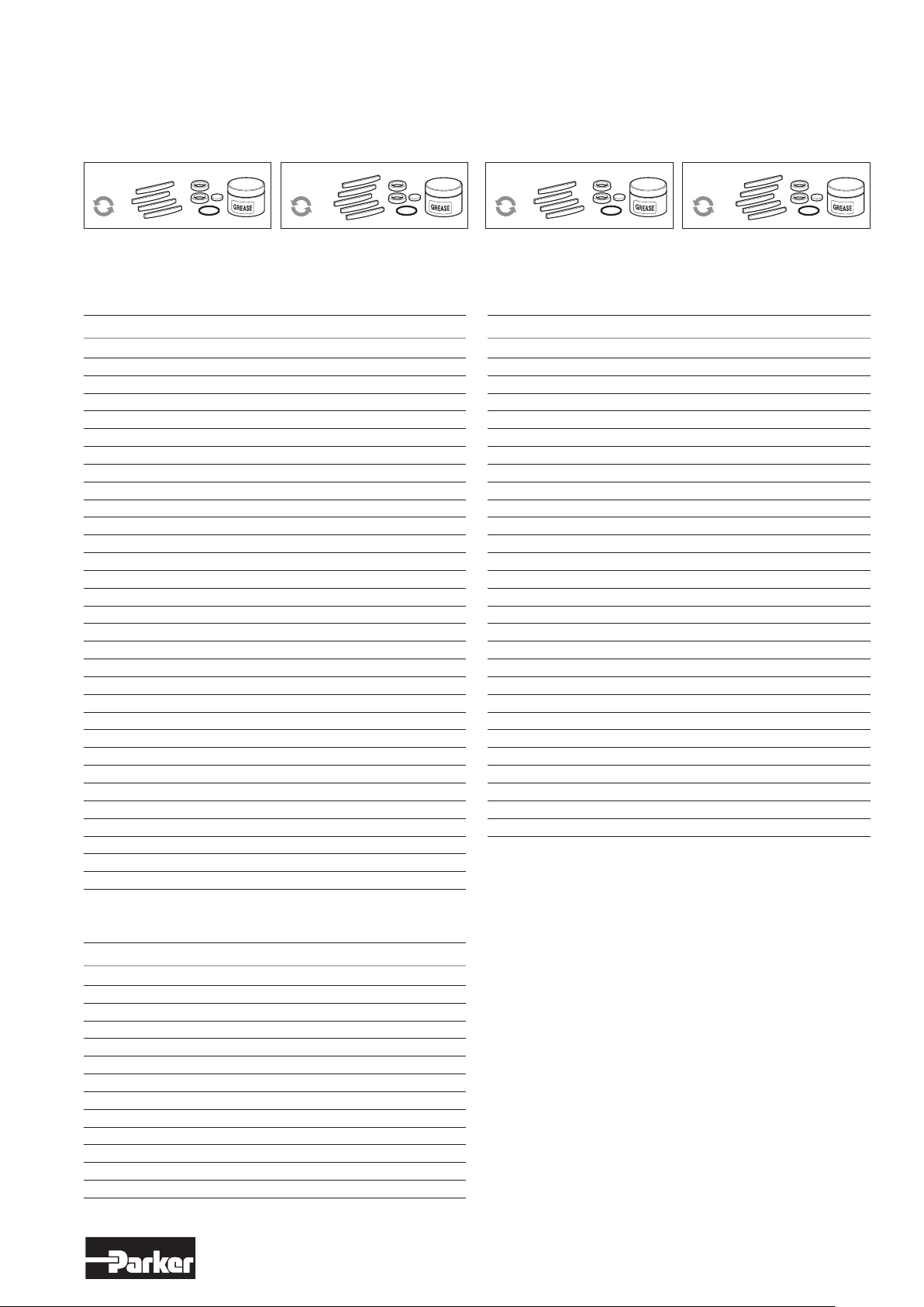
9.1 Service Kits
The following kits are available for the basic motors, consisting
of vanes, (springs), silencers, O-rings, seals and 50 g of grease.
(USDA-H1 approved)
Optional function "0" and "D" Optional function "C" and "E"
Service kits, vanes for intermittent lubrication-free
operation
Service kits, vanes for continuous lubrication-free operation
For motors Order code
P1V-S002A P1V-6/446083A
P1V-S003A P1V-6/446083A
P1V-S008A P1V-6/446084A
P1V-S012A0 / D0 (to serial no 948688) 9121720601
P1V-S012A0 / D0 (from serial no 948689) 9121720636
P1V-S020A• / D• 9121720602
P1V-S030A• / D• 9121720603
P1V-S060A0E00 9121720604
P1V-S060A0400 9121720604
P1V-S060A0350 9121720604
P1V-S060A0270 9121720604
P1V-S060A0170 9121720604
P1V-S060A0072 9121720604
P1V-S060A0063 9121720604
P1V-S060A0048 9121720605
P1V-S060A0030 9121720605
P1V-S060A0015 9121720605
P1V-S060A0010 9121720605
P1V-S090A0C00 P1V-6/444919A
P1V-S090A0350 P1V-6/444919A
P1V-S090A0270 P1V-6/444919A
P1V-S090A0170 P1V-6/444919A
P1V-S090A0063 P1V-6/444919A
P1V-S090A0048 P1V-6/444919B
P1V-S090A0030 P1V-6/444919B
P1V-S120A•800 9121720606
P1V-S120A•270 9121720606
P1V-S120A•110 9121720606
P1V-S120A•078 9121720607
P1V-S120A•032 9121720607
P1V-S120A•012 9121720607
For motors Order code
P1V-S012AC / DC (to serial no 948688) 9121720608
P1V-S012AC / DC (from serial no 948689) 9121720637
P1V-S020A• / D• 9121720609
P1V-S030A• / D• 9121720610
P1V-S060ACE00 9121720611
P1V-S060AC400 9121720611
P1V-S060AC350 9121720611
P1V-S060AC270 9121720611
P1V-S060AC170 9121720611
P1V-S060AC072 9121720611
P1V-S060AC063 9121720611
P1V-S060AC048 9121720612
P1V-S060AC030 9121720612
P1V-S060AC015 9121720612
P1V-S060AC010 9121720612
P1V-S090ACC00 On request
P1V-S090AC350 On request
P1V-S090AC270 On request
P1V-S090AC170 On request
P1V-S090AC063 On request
P1V-S090AC048 On request
P1V-S090AC030 On request
P1V-S120A•800 9121720613
P1V-S120A•270 9121720613
P1V-S120A•110 9121720613
P1V-S120A•078 9121720614
P1V-S120A•032 9121720614
P1V-S120A•012 9121720614
• : 0 or D, C or E
Service kits for high torque motors
For motors Order code
P1V-S028A0017 P1V-6/4447861B
P1V-S028A0008 P1V-6/4447861B
P1V-S028A0005 P1V-6/4447861B
P1V-S028A0003 P1V-6/4447861C
P1V-S028A0002 P1V-6/4447861C
P1V-S057A0015 P1V-6/4447871D
P1V-S057A0011 P1V-6/4447871D
P1V-S057A0007 P1V-6/4447871D
P1V-S057A0004 P1V-6/4447871E
P1V-S086A0015 P1V-6/4449191C
P1V-S086A0011 P1V-6/4449191C
P1V-S086A0007 P1V-6/4449191C
P1V-S086A0004 P1V-6/4449191D
9
www.parker.com/euro_pneumatic
Page 10
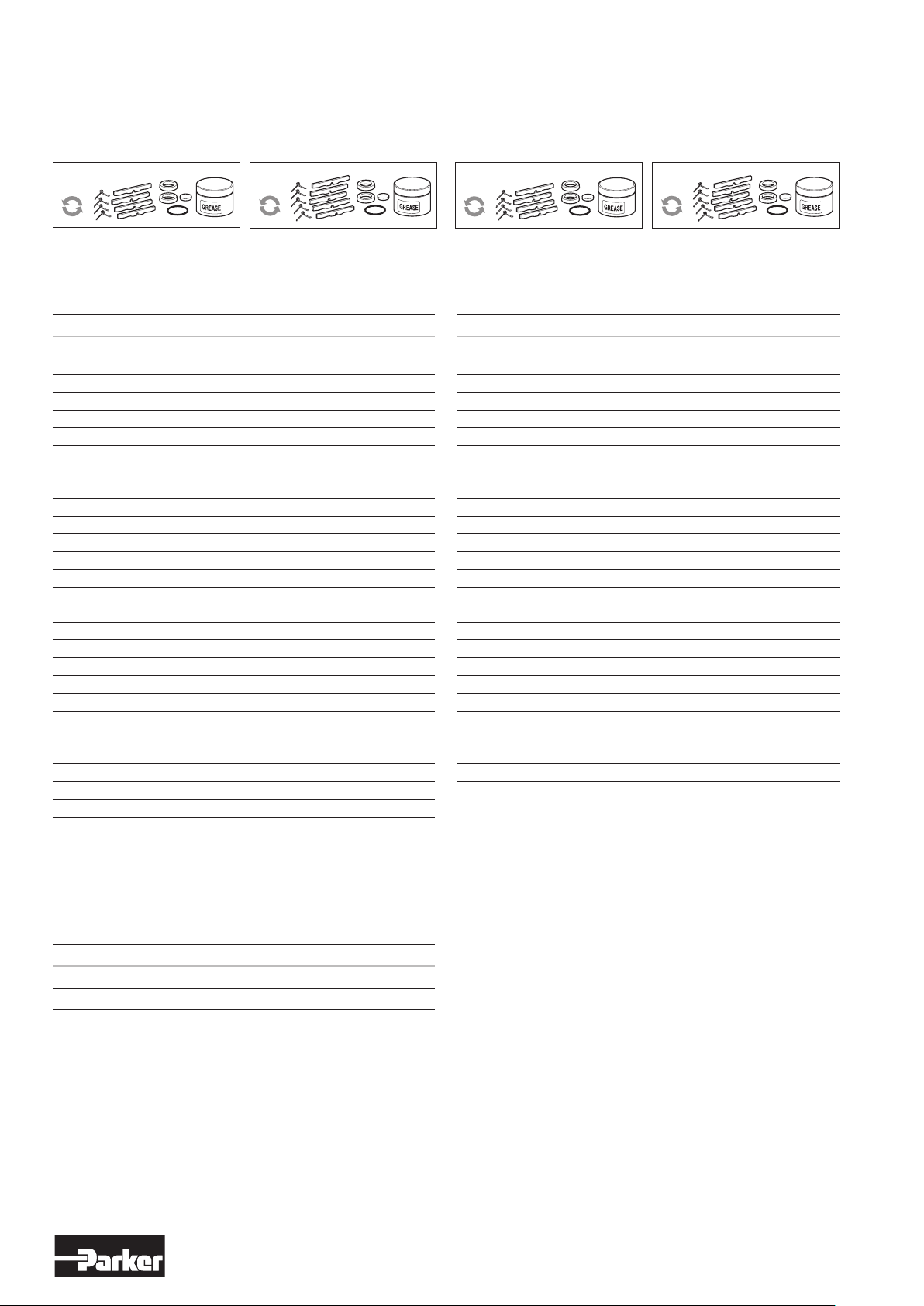
9.1 Service Kits
The following kits are available for the basic motors, consisting
of vanes, (springs), silencers, O-rings, seals and 50 g of grease.
(USDA-H1 approved)
Optional function "Z" and "F" Optional function "M" and "G"
Service kits, spring-loaded vanes for intermittent
lubrication-free operation
Service kits, spring-loaded vanes for continuous
lubrication-free operation
For motors Order code
P1V-S012AZ / DZ (to serial no 948688) 9121720615
P1V-S012AZ / DZ (from serial no 948689) 9121720638
P1V-S020A• / D• 9121720616
P1V-S030A• / D• 9121720617
P1V-S060AZE00 9121720618
P1V-S060AZ400 9121720618
P1V-S060AZ350 9121720618
P1V-S060AZ270 9121720618
P1V-S060AZ170 9121720618
P1V-S060AZ072 9121720618
P1V-S060AZ048 9121720619
P1V-S060AZ072 9121720619
P1V-S060AZ063 9121720619
P1V-S060AZ010 9121720619
P1V-S090AZC00 On request
P1V-S090AZ350 On request
P1V-S090AZ270 On request
P1V-S090AZ170 On request
P1V-S090AZ063 On request
P1V-S090AZ048 On request
P1V-S090AZ030 On request
P1V-S120A•800 9121720620
P1V-S120A•270 9121720620
P1V-S120A•110 9121720620
P1V-S120A•078 9121720621
P1V-S120A•032 9121720621
P1V-S120A•012 9121720621
• : Z or F, M or G
For motors Order code
P1V-S012AM / DM (to serial no 948688) 9121720622
P1V-S012AM / DM (from serial no 948689) 9121720639
P1V-S020A• / D• 9121720623
P1V-S030A• / D• 9121720624
P1V-S060AME00 9121720625
P1V-S060AM400 9121720625
P1V-S060AM270 9121720625
P1V-S060AM170 9121720625
P1V-S060AM072 9121720625
P1V-S060AM048 9121720626
P1V-S060AM030 9121720626
P1V-S060AM010 9121720626
P1V-S090AMC00 On request
P1V-S090AM350 On request
P1V-S090AM270 On request
P1V-S090AM170 On request
P1V-S090AM063 On request
P1V-S090AM048 On request
P1V-S090AM030 On request
P1V-S120A•800 9121720627
P1V-S120A•270 9121720627
P1V-S120A•110 9121720627
P1V-S120A•078 9121720628
P1V-S120A•032 9121720628
P1V-S120A•012 9121720628
Service kits for brake module for motors with brakes
For motors Order code
P1V-S020AD and P1V-S030AD P1V-6/446096A
P1V-S120AD P1V-6/4460961B
Comment: To perform a full service on a brake motor, you will need
a normal service kit as well as a service kit for the brake module.
10
www.parker.com/euro_pneumatic
Page 11

10. Shut Down and Storage
13. EC-Declaration of Incorporation
• Turn the air supply to “OFF”.
• Disconnect the air motor from the air supply.
• Disconnect the air motor from the equipment it is attached to.
• Remove the silencer package (if one is installed).
• Blow clean and dry air (using a low pressure) into the air-inlet
port of the air motor.
• Drip a couple of oil-drops into the inlet port and turn the shaft
by hand to distribute the oil. Recommended oil:
see chapter 7 – “Lubricants”.
• Close all connections.
• The air motor may now be stored until needed again.
11. Technical Data
Please refer to the technical catalogue PDE2554TC
EC-Declaration of Incorporation in accordance with the
EC Machinery Directive 2006/42/EC, Annex IIB
As supplier of the partly completed machine we declare that:
• the essential requirements of the Directive 2006/42/EC and where
applicable the other Directives and Standards listed below apply to
the specified machine.
• the relevant technical documentation is compiled in accordance with
part B of Annex VII.
• the relevant technical documentation in accordance with part B of
Annex VII will be transmitted in response to a reasonable request by
the national authorities in printed form or in electronic form (pdf).
Required documents have been filed - under Directive 2014/34/EU,
Annex VIII - with the following authority:
IBExU, Institut für Sicherheitstechnik GmbH EU reference number
IBExU15ATEXB006 X.
Supplier Parker Hannifin Manufacturing
Germany GmbH & Co. KG
Pneumatic Division Europe
Industriestrasse 8
70794 Filderstadt Germany
12. CE marking
The air motors are supplied as “Components for installation” – the
installer is responsible for ensuring that the motors are installed safely
in the overall system.
Parker Pneumatic guarantees that its products are safe, and as a
supplier of pneumatic equipment we ensure that the equipment is
designed and manufactured in accordance with the applicable EU
directive.
Most of our products are classed as components as defined by various
directives, and although we guarantee that the components satisfy the
fundamental safety requirements of the directives to the extent that they
are our responsibility, they do not usually carry the CE mark.
Nevertheless, most P1V-S motors carry the CE mark because they are
ATEX certified (for use in explosive atmospheres).
The following are the currently applicable directives:
• Machinery Directive(essential health and safety requirements relating
to the design and structure of machines and safety components)
• EMC Directive
• Simple Pressure Vessels Directive
• Low Voltage Directive
• ATEX Directive (ATEX = ATmosphere EXplosive)
11
www.parker.com/euro_pneumatic
Page 12
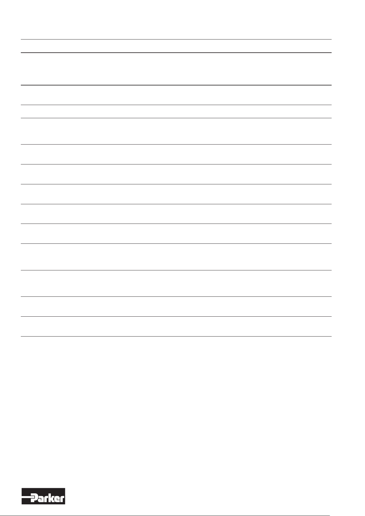
14. Troubleshooting
Fault Cause Corrective Action
Torque Speed Motor Motor Motor operates,
too low too low does is hot but becomes
not slower during
turn operating
Dirt or foreign Check and clean
• • •
objects in motor
• • • Motor is rusty on Check and clean
Incorrect gap play Re-adjust gap play
• • • • • between rotor and of motor
bearing cover
Air pressure is Increase air
• •
too low pressure
No air; shut-off Open shut-off
•
valve is closed valve
Hose diameter Use a hose with a
•
is too small larger diameter
Exhaust air is Check and correct
• •
being throttled
Internal parts Disassemble and
• • • •
are frozen repair motor
Compressor is too Supply larger
• • small; air volume volume
is too low
Air supply is Optimise
• • located too far installation
from the motor
Insufficient Provide the required
• • •
lubrication air quality
Worn vanes or Exchange vanes
• • • •
vanes are jammed
12
www.parker.com/euro_pneumatic
Page 13
Additional safety instructions for installation in explosive atmospheres
Serious, even fatal, damage or injury may be caused by the hot moving parts of the P1V-S motors in the presence of
explosive gas mixtures and concentrations of dust.
All installation, connection, commissioning, servicing and repair
work on P1V-S motors must be carried out by qualified personnel
taking account of the following:
• These instructions.
• Notices on the motor.
• All other planning documents, commissioning instructions
and connection diagrams associated with the application.
• Provisions and requirements specific to the application.
• Applicable national/international regulations (explosion protection, safety and accident prevention).
Real life applications
P1V-S motors are designed to provide rotary movement in
industrial applications, and should only be used in accordance with the instructions in the technical specifications in the
catalogue, and within the operating range indicated on the motor
housing. The motors meet the applicable standards and requirements of the Machinery Directive 2014/34/EU (ATEX)
The motors must not be used as brakes in
explosive atmospheres.
Braking involves driving the motor against the direction of rotation for which the motor is supplied with compressed air. The
motor is then operating as a compressor, and there is a corresponding increase in temperature.
Installation requirements in potentially explosive
atmospheres
• The temperature of the supply air must not exceed the
ambient temperature.
• The P1V-S may be installed in any position.
• An air treatment unit must be attached to the inlet of the
P1V-S air motor.
• In a potentially explosive atmosphere, none of the
motor ports may be blocked because this may cause an
increase in temperature. The air from the port must be taken
to the silencer or, preferably, outside the potentially explosive
area.
• The P1V-S motor must be connected to ground at all
times, through its support, a metallic tube or separate conductor.
• The outlet of the P1V-S motor must not open within a potentially explosive area, but must be passed to the silencer
or, preferably, removed and released outside the potentially
explosive area.
• The P1V-S motor may only drive units that are ATEX certified.
• Ensure that the motor is not exposed to forces greater than
those permitted in accordance with the catalogue.
The motors must not be used underground in mines
susceptible to firedamp and/or combustible dust. The motors
are intended for use in areas in which explosive atmospheres
caused by gases, vapours or mists of combustible liquids, or air/
dust mixtures may be expected to occur during normal use (infrequently)
Checklist
Before using the motors in a potentially explosive atmosphere,
you should check the following:
Do the motor specifications match the classification of the area of
use in accordance with Directive 94/9/EG
(previously ATEX 100a)?
• Equipment group
• Equipment category
• Zone
• Temperature class
• Max. surface temperature
1. When installing the motor, are you certain that there is no
potentially explosive atmosphere, oil, acids, gases, vapours
or radiation?
2. Is the ambient temperature as specified in the technical data
in the catalogue at all times?
3. Are you certain that the P1V-S motor is adequately
ventilated and that no additional heat is added
(for example in the shaft connection)?
4. Are all the driven mechanical components ATEX certified?
Measuring the temperature on the outside of the
P1V-S motor (only when used in potentially explosive
areas)
During the commissioning process, it is essential to measure
temperature increases at the indicated positions on the outside
of the P1V-S motor.
These measurements can be taken using standard
thermometers.
Checking the motor during operation
The motor must be kept clean on the outside, and a layer of dirt
thicker than 5 mm must never be allowed to form.
Strong solvents should not be used for cleaning, because they
can cause the seal (material NBR/FPM) around the drive shaft to
swell, potentially increasing the temperature.
13
www.parker.com/euro_pneumatic
Page 14
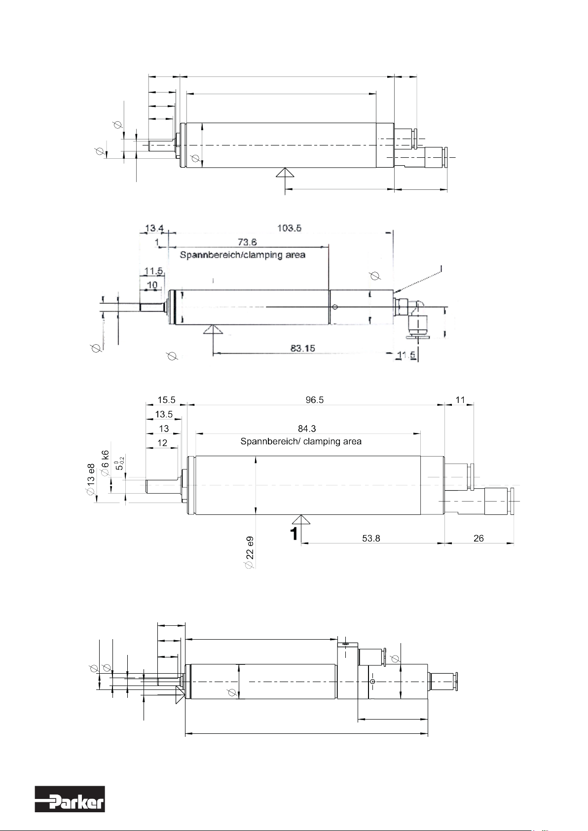
15.5
105.5
11
Motor P1V-S008A0190
Motor P1V-S008A0130
13e8
Motor P1V-S003B0100
1 = measuring point for temperature measurement
4 k6
13.5
13
6k6
12
Spannbereich/ clamping area
93.3
22 e9
-0.2
0
5
1
-0.1
0
3.5
8 e8
1
53.8
26
air outlet
17
15.5
Motor P1V-S008AQ00
Motor P1V-S008A0700
Motor P1V-S002A0130
Motor P1V-S002A0095
4 k6
8 e8
13.5
11.5
10
Spannbereich/clamping area
75
17
3.5
1
6.5
34
119
1 = measuring point for temperature measurement
17 e8
14
www.parker.com/euro_pneumatic
Page 15
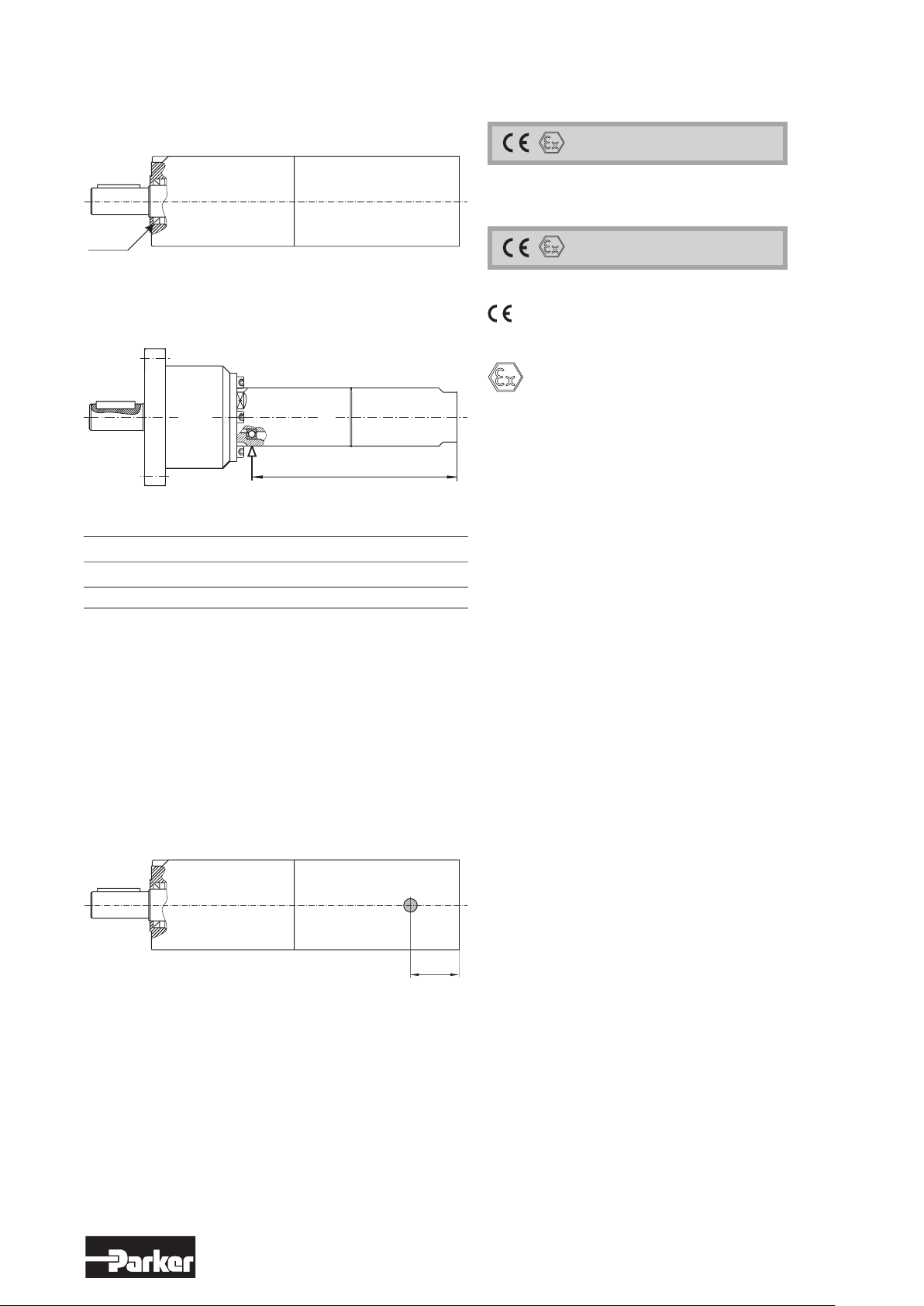
The temperature is measured on the metal surface next to the
45
x
seal around the output shaft on all P1V-S012, P1V-S020,
P1V-S028, P1V-S030, P1V-S057, P1V-S060, P1V-S086 and
P1V-S090 motors.
Marking of products
II2 GD c IIC T6 (80 °C) X
Planetary gearbox
Seal
Motor part
Motors P1V-S030A0023 and P1V-S030A0010
Motor x [mm]
P1V-S030A0023 146
P1V-S030A0010 147,5
The maximum temperature is reached after approximately 1.5
hours of operation, and the difference in temperature between
the motor and the ambient temperature must not exceed 40 °C.
If the temperature difference at the seal of a P1V-S 120 to
900 watts exceeds 40 °C, you should stop the motor
immediately and contact Parker Hannifin.
The following applies to the P1V-S120 series:
The temperature is measured on the metal surface at a point 45
mm from the port end of the motor housing, on all P1V-S120.
Planetary gearbox
Motor part
II2 GD c IIC T5 (95 °C) X
Communatuté Européenne = EU
CE marking shows that as a manufacturer, Parker Han-
nifin meets the guidelines specified by the EU
Ex means that this product is intended for use in a po-
tentially explosive area
II stands for the equipment group (I = mines and II = other
places liable to be endangered)
2GD stands for equipment category
2G means the equipment can be used in zones 1 and
2 where there is a risk involving gas, vapour or mist of
combustible liquids and 2D in zones 21 and 22 where
there is a risk involving dust .
2GD means the equipment can be used in zones
1, 2, 21 and 22.
c Safe design (prEN 13463-5)
IIC Explosion group, P1V-S air motors are tested to the hig-
hest standards in terms of test gases, and can be installed in the presence of all gases without
restriction.
T6 If equipment is in temperature class T6, the maximum
surface temperature must not exceed 85 °C.
(To guarantee this, the product has been tested to
ensure that the maximum is 80 °C. This provides a safety margin of 5 °K.)
T5 If equipment is in temperature class T5, the maximum
surface temperature must not exceed 100 °C. (To guarantee this, the product has been tested to ensure
that the maximum is 95 °C. This provides a safety margin of 5 °K.)
(80 °C) Maximum permitted surface temperature on the motor
in atmospheres containing potentially explosive dust.
X Note special conditions
The maximum temperature is reached after approximately 1.5
hours of operation and the difference in temperature between the
motor and the ambient temperature must not exceed 55 °C.
If the temperature difference at this point on a P1V-S120
exceeds 55 °C, you should stop the motor immediately
and contact Parker Hannifin.
Test certificate number IBExU04ATEXB004 X from
IBExU Institut für Sicherheitstechnik GmbH, D-09599
Freiberg, Germany
15
www.parker.com/euro_pneumatic
Page 16

Parker Worldwide
Europe, Middle East, Africa
AE – United Arab Emirates,
Dubai
Tel: +971 4 8127100
[email protected]
AT – Austria, Wiener Neustadt
Tel: +43 (0)2622 23501-0
[email protected]
AT – Eastern Europe, Wiener
Neustadt
Tel: +43 (0)2622 23501 900
[email protected]
AZ – Azerbaijan, Baku
Tel: +994 50 2233 458
[email protected]
BE/LU – Belgium, Nivelles
Tel: +32 (0)67 280 900
[email protected]
BG – Bulgaria, Soa
Tel: +359 2 980 1344
[email protected]
BY – Belarus, Minsk
Tel: +48 (0)22 573 24 00
[email protected]
CH – Switzerland, Etoy
Tel: +41 (0)21 821 87 00
[email protected]
CZ – Czech Republic, Klecany
Tel: +420 284 083 111
[email protected]
DE – Germany, Kaarst
Tel: +49 (0)2131 4016 0
[email protected]
DK – Denmark, Ballerup
Tel: +45 43 56 04 00
[email protected]
ES – Spain, Madrid
Tel: +34 902 330 001
[email protected]
FI – Finland, Vantaa
Tel: +358 (0)20 753 2500
parker.[email protected]
FR – France, Contamine s/Arve
Tel: +33 (0)4 50 25 80 25
[email protected]
GR – Greece, Athens
Tel: +30 210 933 6450
[email protected]
HU – Hungary, Budaörs
Tel: +36 23 885 470
[email protected]
IE – Ireland, Dublin
Tel: +353 (0)1 466 6370
[email protected]
IT – Italy, Corsico (MI)
Tel: +39 02 45 19 21
[email protected]
KZ – Kazakhstan, Almaty
Tel: +7 7273 561 000
[email protected]
NL – The Netherlands, Oldenzaal
Tel: +31 (0)541 585 000
[email protected]
NO – Norway, Asker
Tel: +47 66 75 34 00
[email protected]
PL – Poland, Warsaw
Tel: +48 (0)22 573 24 00
[email protected]
PT – Portugal, Leca da Palmeira
Tel: +351 22 999 7360
[email protected]
RO – Romania, Bucharest
Tel: +40 21 252 1382
[email protected]
RU – Russia, Moscow
Tel: +7 495 645-2156
[email protected]
SE – Sweden, Spånga
Tel: +46 (0)8 59 79 50 00
[email protected]
SK – Slovakia, Banská Bystrica
Tel: +421 484 162 252
[email protected]
SL – Slovenia, Novo Mesto
Tel: +386 7 337 6650
[email protected]
TR – Turkey, Istanbul
Tel: +90 216 4997081
[email protected]
UA – Ukraine, Kiev
Tel: +48 (0)22 573 24 00
[email protected]
UK – United Kingdom, Warwick
Tel: +44 (0)1926 317 878
[email protected]
ZA – South Africa, Kempton Park
Tel: +27 (0)11 961 0700
[email protected]
North America
CA – Canada, Milton, Ontario
Tel: +1 905 693 3000
US – USA, Cleveland
Tel: +1 216 896 3000
Asia Pacific
AU – Australia, Castle Hill
Tel: +61 (0)2-9634 7777
CN – China, Shanghai
Tel: +86 21 2899 5000
HK – Hong Kong
Tel: +852 2428 8008
IN – India, Mumbai
Tel: +91 22 6513 7081-85
JP – Japan, Tokyo
Tel: +81 (0)3 6408 3901
KR – South Korea, Seoul
Tel: +82 2 559 0400
MY – Malaysia, Shah Alam
Tel: +60 3 7849 0800
NZ – New Zealand, Mt Wellington
Tel: +64 9 574 1744
SG – Singapore
Tel: +65 6887 6300
TH – Thailand, Bangkok
Tel: +662 186 7000
TW – Taiwan, Taipei
Tel: +886 2 2298 8987
South America
AR – Argentina, Buenos Aires
Tel: +54 3327 44 4129
BR – Brazil, Sao Jose dos Campos
Tel: +55 800 727 5374
CL – Chile, Santiago
Tel: +56 2 623 1216
MX – Mexico, Tolu c a
Tel: +52 72 2275 4200
European Product Information Centre
Free ph one: 0 0 800 27 27 5374
(from AT, BE, CH, CZ, D E, DK , EE, ES, FI,
FR, IE , IL, I S, IT, LU, MT, NL, NO, PL, PT, RU,
SE, SK, UK, ZA)
© 2015 Parker Hannin Corporation. All rights reserved.
Parker Hannifin Ltd.
Tachbrook Park Drive
Tachbrook Park,
Warwick, CV34 6TU
United Kingdom
Tel.: +44 (0) 1926 317 878
Fax: +44 (0) 1926 317 855
[email protected]
www.parker.com
4601503-P1V-S - V4 - August 2015
Your local authorized Parker distributor
 Loading...