

Parker P1/PD, P1/PD 018, P1/PD 028, P1/PD 045, P1/PD 100 Service Manual
...
P1/PD Series: B-Mod Service Information
Medium Pressure Axial Piston Pumps
Bulletin HY28-2708-02/SVC/EN
Effective: July 2019 Replaces: March 29, 2019

Bulletin HY28-2708-02/SVC/EN | July 2019
Contents
Medium Pressure Axial Piston Pumps
P1/PD B-mod Service Information
Contents
B-Mod Pump Identication ..................................................................................................................................... 3
B-Mod Controls vs A-mod Controls ........................................................................................................................ 4
General Information ................................................................................................................................................. 5
Typical Characteristics ............................................................................................................................................ 6
Parts Data
018, 028 B-mod Pump Exploded View ................................................................................................................... 7
045 B-mod Pump Exploded View ........................................................................................................................... 8
018, 028, 045 B-mod Pump Parts .......................................................................................................................... 9
060, 075, 085, 100, 140 B-mod Pump Exploded View ......................................................................................... 10
060, 075, 085, 100, 140 B-mod Pump Parts ........................................................................................................ 11
Volume Stop Control ............................................................................................................................................. 12
Thru Drive Couplings and O-rings ......................................................................................................................... 13
C0 B-mod Control Exploded View ........................................................................................................................ 14
L0 B-mod Control Exploded View ......................................................................................................................... 15
L2 B-mod Control Exploded View ......................................................................................................................... 16
AM B-mod Control Exploded View ....................................................................................................................... 17
C0 to L0 B-mod Conversion Guide ....................................................................................................................... 18
C0 to L2 B-mod Conversion Guide ....................................................................................................................... 19
C0 to AM B-mod Conversion Guide ..................................................................................................................... 20
L0 / L2 to C0 B-mod Conversion Guide .............................................................................................................. 21
L0 to L2 B-mod Conversion Guide ....................................................................................................................... 22
L2 to L0 B-mod Conversion Guide ....................................................................................................................... 23
L0 to AM B-mod Conversion Guide ...................................................................................................................... 24
L2 to AM B-mod Conversion Guide ...................................................................................................................... 25
AM to C0 B-mod Conversion Guide ..................................................................................................................... 26
AM to L0 B-mod Conversion Guide ...................................................................................................................... 27
AM to L2 B-mod Conversion Guide ...................................................................................................................... 28
075, 085, 100, 140 Torque Limiter ......................................................................................................................... 29
Electronic Unload Control B-mod Exploded View ................................................................................................ 30
Parts Kits ............................................................................................................................................................... 32
Assembly/Disassembly information
Compensator Procedures ..................................................................................................................................... 33
Pump Service Procedures ..................................................................................................................................... 35
Pump Inspection Procedures ................................................................................................................................ 37
Component Rework Limits .................................................................................................................................... 38
018, 028, 045 Assembly Procedures .................................................................................................................... 39
060, 075, 085, 100, 140 Assembly Procedures .................................................................................................... 43
Assembly Tools ..................................................................................................................................................... 47
Rotation Change ................................................................................................................................................... 51
Test Procedure ...................................................................................................................................................... 53
Test Criteria & Start-up Procedures....................................................................................................................... 55
Trouble Shooting ................................................................................................................................................... 56
Conversions and Formulas ................................................................................................................................... 58
Warning ................................................................................................................................................................. 59
Parker Hannin Corporation
Hydraulic Pump and Power Systems Division
2
Marysville, Ohio USA
Bulletin HY28-2708-02/SVC/EN | July 2019
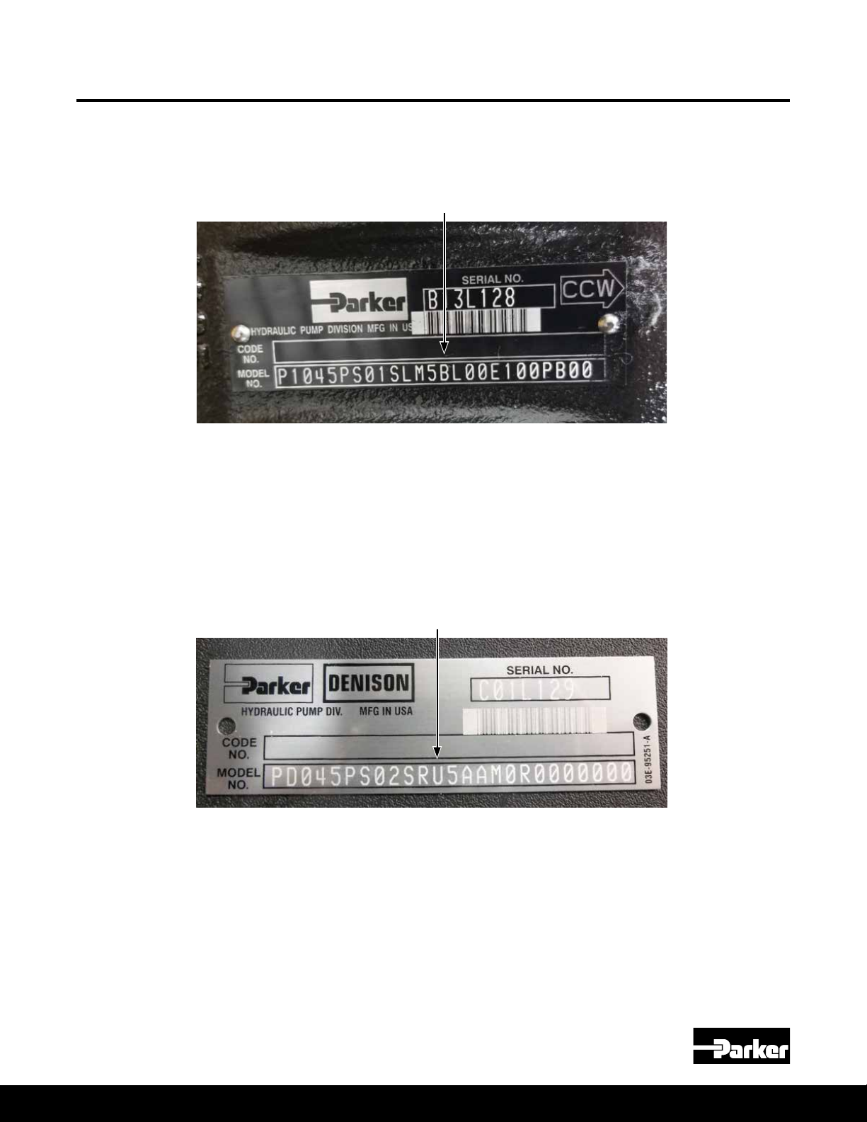
B-Mod Pump Identification
This service manual is to be used for P1/PD Design Series B (B-mod) pumps.
In order to identify which series of pump you have, please refer to the Series
Designation spot in the P1/PD model code as shown below.
The design series is based on the type of control selected. B-mod pumps use
the C, L, and AM controls. All other control types are Design Series A (A-mod).
There are however two exceptions. Both exceptions are on the 45 & 60cc pumps.
One exception is when the load sense (L) or remote compensator (AM) is used
in combination with the torque limiting control (ALT or AMT). The ALT or AMT on
the 45 & 60cc pumps is still the A-mod design series. The other exception is if
the Universal “U” conguration model code option is selected with the 45 or 60cc
pump. On those two displacements, the Universal “U” option is also still an A-mod
design series.
Medium Pressure Axial Piston Pumps
P1/PD B-mod Service Information
Design Series Designation
"U" Universal Designation
For service information on A-mod pumps please refer to
Bulletin HY28-2665-02/SVC/EN. The latest edition can be found at
www.parker.com/HPS.
NOTE: A-mod and B-mod controls are NOT Interchangeable! Adapter block
is required to put a B-mod control on an A-mod or an A-mod control on a
B-mod pump. See Parts Kits page for adapter block part numbers.
Parker Hannin Corporation
Hydraulic Pump and Power Systems Division
Marysville, Ohio USA
3
Bulletin HY28-2708-02/SVC/EN | July 2019
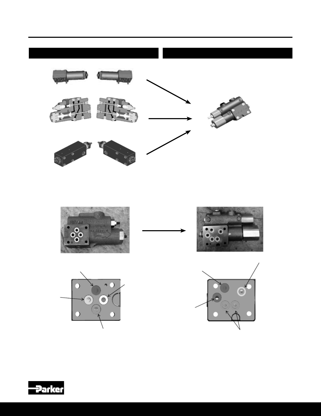
B-Mod Controls vs A-mod Controls
Design Series A Design Series B
Medium Pressure Axial Piston Pumps
P1/PD B-mod Service Information
Pressure Limiter:
C00, C10 (Left)
Pressure sense:
L00, L20 (Left)
Pilot operated
pressure limiter:
AM (Left)
Pressure Limiter:
C00, C10 (Right)
Pressure sense:
L00, L20 (Right)
Pilot operated
pressure limiter:
AM (Right)
"All in one compensator":
C00, (C00 replaces C10) L00,
L20, AM (Left and Right)
Control
or Bias
Tank
Pressure
Tank
Pressure LS
Bias or
Control
Pressure
Pmax
Control
Standard NG6/D03 Pattern Custom Control Pad Pattern
NOTE: Bolt pattern & size remains the same. No change to housing casting required.
Parker Hannin Corporation
Hydraulic Pump and Power Systems Division
4
Marysville, Ohio USA

Bulletin HY28-2708-02/SVC/EN | July 2019
General Information
Medium Pressure Axial Piston Pumps
P1/PD B-mod Service Information
Model Coding Information
Mounting
Side Load Capability
Fluid Connections
System Relief Valves
Recommended Fluids
Viscosity Index
Temperature
Maintenance
Fluid Cleanliness
For model code designation meaning and general model code information please see
P1/PD sales catalog HY28-2665-01/P1/EN.
These pumps are designed to operate in any position. For shaft up, contact factory.
The pump shaft must be in alignment with the shaft of the source driver and should be
checked with a dial indicator. The mating pilot bore and coupling must be concentric.
This concentricity is particularly important if the shaft is rigidly connected to the driven
load without a exible coupling.
Splined: The shafts will accept a maximum misalignment of 0.005 in (0.15mm) total
indicator reading. Angular misalignment at the external and internal spline axis must be
less than ± 0,002 mm per mm of shaft radius, ± 0.002 inches per inch of shaft radius.
The coupling interface must be lubricated. PARKER recommends lithium molydisulde
or similar grease. The internal coupling should be hardened to Rc 27-34 and must conform
to SAE-J498c, class 5 at root side t.
Keyed: High strength heat treated keys must be used. Replacement keys must be hardened
to 27-34 Rc. The key corners must be chamfered 0.032-0.040 in (0.81-1.0 mm) at 45° to
clear radii that exist in the keyway.
The P1/PD series is designed for inline-drive. Side loading on the shaft is not recommended.
If this is unavoidable consult your nearest Parker representative.
Connect inlet and outlet lines to the port block of the pump. The maximum case pressure is
2 bar (30 psi) continuous, 4 bar (60 psi) intermittent. The case pressure must never exceed
inlet pressure by more than .5 bar (7 psi). When connecting case drain line make certain
that drain plumbing passes above highest point of the pump before passing to the reservoir.
The case leakage line must be of sufcient size to prevent back pressure in excess of 2 bar
(30 psi) and returned to the reservoir below the surface of the oil as far from the supply inlet
as possible. All uid lines, whether pipe, tubing, or hose must be adequate size and strength
to assure free ow through the pump. An undersize inlet line will prevent the pump from
operating properly at full rated speed. An undersize outlet line will cause back pressure and
cause heat generation and increased noise. Flexible hose lines are recommended. If rigid
piping is used, the workmanship must be accurate to eliminate strain on the pump port block
or to the uid connections. Sharp bends in the lines must be eliminated wherever possible.
All system piping must be cleaned and ushed before installing pump. Make sure the entire
hydraulic system is free of dirt, lint, scale, or other foreign material.
CAUTION: Do not use galvanized pipe. Galvanized coating can ake off with continued use.
Although the P1/PD series pumps have very fast off-stroke compensator response, system
relief valves are recommended in all cases for safety considerations.
The uid recommended for use in these pumps has a petroleum base and contains agents
which provide oxidation inhibition and anti-rust, anti-foam and de-aerating properties as
described in Parker standard HF-1. Where anti-wear additive uids are specied, see
Parker standard HF-0.
90 V. I. minimum. Higher values extend the range of operating temperature but may reduce
the service life of the uid. Viscosity cannot be lower than 7 cSt.
Determined by the viscosity characteristics of the uid used. Because high temperatures
degrade seals, reduce the service life of the uid and create hazards, uid temperature
should not exceed 230°F (110°C) at the case drain.
The pump is self-lubricating and preventative maintenance is limited to keeping system
uid clean by changing lters frequently. Keep all ttings and screws tight. Do not operate
at pressures and speeds in excess of the recommended limit. If the pump does not
operate properly, check the troubleshooting chart before attempting to overhaul the unit.
Overhauling may be accomplished by referring to the disassembly, rework limits of wear
parts, and assembly procedures as provided in this service manual.
Fluid must be cleaned before and continuously during operation, by lters that maintain a
cleanliness level of ISO 20/18/14. Better cleanliness levels will signicantly extend the life
of the components. As contaminant generation may vary with each application, each must
be analyzed to determine proper ltration to maintain the required cleanliness level.
Parker Hannin Corporation
Hydraulic Pump and Power Systems Division
Marysville, Ohio USA
5
Bulletin HY28-2708-02/SVC/EN | July 2019
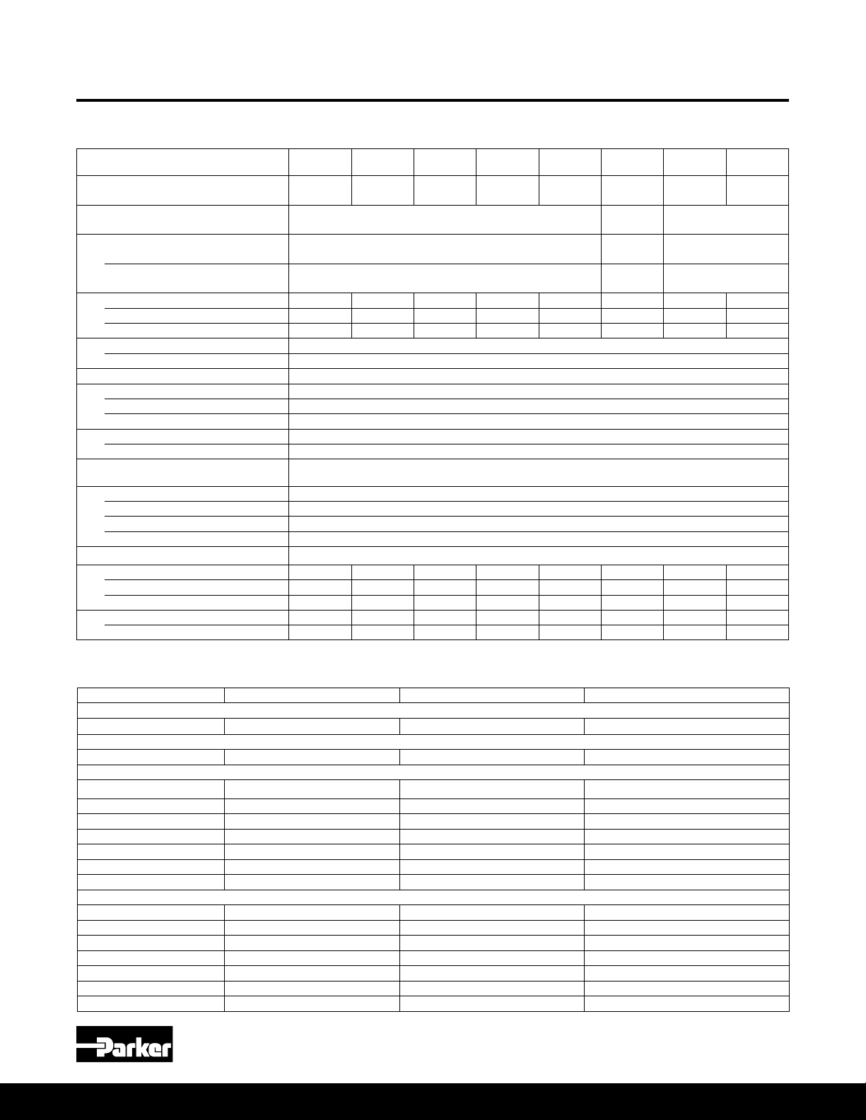
Typical Characteristics
Medium Pressure Axial Piston Pumps
P1/PD B-mod Service Information
Technical Data
/rev
P1/PD
018
3500 3400 3100 2800 2700 2700 2500 2400
°F
2
760 1555 3208 4548 5041 5041 12027 21400
2
793 1618 3268 4687 5207 5207 12402 22343
Model
Maximum Displacement, cm
Outlet Pressure – Continuous
P1 Maximum Speed (1.3 bar abs inlet), rpm
P1 (1.0 bar abs inlet), rpm 3300 3200 2800 2500 2400 2400 2250 2100
P1 (0.8 bar abs inlet), rpm 2900 2900 2400 2200 2100 2100 1900 1800
PD Maximum Speed (1.0 bar abs inlet), rpm
PD (0.8 bar abs inlet), rpm 1800
Minimum Speed, rpm 600
Inlet Pressure – Maximum 11 bar absolute (160 psi)
Case Pressure – Peak, bar 4.0 bar absolute (58 psi) and less than 0.5 bar (7.3 psi) above inlet pressure
Fluid Temperature Range, °C
Fluid Viscosity – Rated, cSt 7 to 160
Optimum Range, cSt 14-50 cSt.
Max. Intermittent, cSt 5000 (for cold starting)
Min. Intermittent, cSt 5
Fluid Contamination – Rated, ISO 20/18/14
Weight – End Port, kg (lb) 13.4 (29.5) 17.7 (39.0) 23 (50) 29 (64) 30 (66) 30 (66) 51 (112) 66 (145)
Side Port, kg (lb) 14.2 (31.3) 18.1 (40.0) 24 (52) 30 (67) 31 (68) 31 (68) 53 (117) 67 (147)
Thru-Drive, kg (lb) 15 (34) 22 (48) 27 (59) 34 (75) 35 (77) 35 (77) 55 (121) 82 (180)
Moment of Inertia kg·mm
Moment of Inertia Thru-Drive kg·mm
*Intermittent pressure is dened as less than 10% of operation time, not exceeding 6 successive seconds.
3
cu.in./rev181.10
Intermittent*
Peak
Rated 1.0 bar absolute (14.5 psi)
Minimum 0.8 bar absolute (11.6 psi)
Rated, bar 2.0 bar absolute (29 psi) and less than 0.5 bar (7.3 psi) above inlet pressure
P1/PD
028
28
1.71
P1/PD
045
45
2.75
280 bar
(4060 psi)
320 bar
(4640 psi)
350 bar
(5075 psi)
P1/PD
060
60
3.66
-40 to +95
-40 to +203
P1/PD
1800
075
75
4.58
P1/PD
085
85
5.19
250 bar
(3600 psi)
300 bar
(4350 psi)
320 bar
(4600 psi)
P1/PD
100
100
6.01
P1/PD
140
140
8.54
280 bar
(4060 psi)
320 bar
(4640 psi)
350 bar
(5075 psi)
Typical Adjustment Ranges and Initial Settings for B-Mod Controls (Unless Customer Specified at Time of Order)
Function Adjustment Range Adjustment Value Recommended or Initial Setting
Pressure compensator settings
C, L, AM Controls 26-280 bar (380-4060 PSI) 55 bar/turn (800 PSI/turn) Default factory setting = 1000 PSI
Load sense differential settings
"L0" and “L2” 10-40 bar (150-580 PSI) 16 bar/turn (230 PSI/turn) 20 bar (290 PSI)
Maximum volume stop
018 100-40% 9% per turn (1.6 cc/turn) 100%
028 100-40% 8.2% per turn (2.3 cc/turn) 100%
045 100-20% 7.5% per turn (3.4 cc/turn) 100%
060 100-30% 6.8% per turn (4.1 cc/turn) 100%
075/085 100-35% 6.2% per turn (4.65 cc/turn) 100%
100 100-50% 5.5% per turn (5.5 cc/turn) 100%
140 100-50% 4.8% per turn (6.72 cc/turn) 100%
Minimum volume stop
018 0-68% 10% per turn (1.8 cc/turn) 0%
028 0-40% 9% per turn (2.6 cc/turn) 0%
045 0-40% 8.2% per turn (3.7 cc/turn) 0%
060 0-50% 4.6% per turn (2.76 cc/turn) 0%
075/085 0-45% 4.3% per turn (3.23 cc/turn) 0%
100 0-45% 3.9% per turn (3.9 cc/turn) 0%
140 0-25% 3.3% per turn (4.62 cc/turn) 0%
Parker Hannin Corporation
Hydraulic Pump and Power Systems Division
6
Marysville, Ohio USA

Bulletin HY28-2708-02/SVC/EN | July 2019
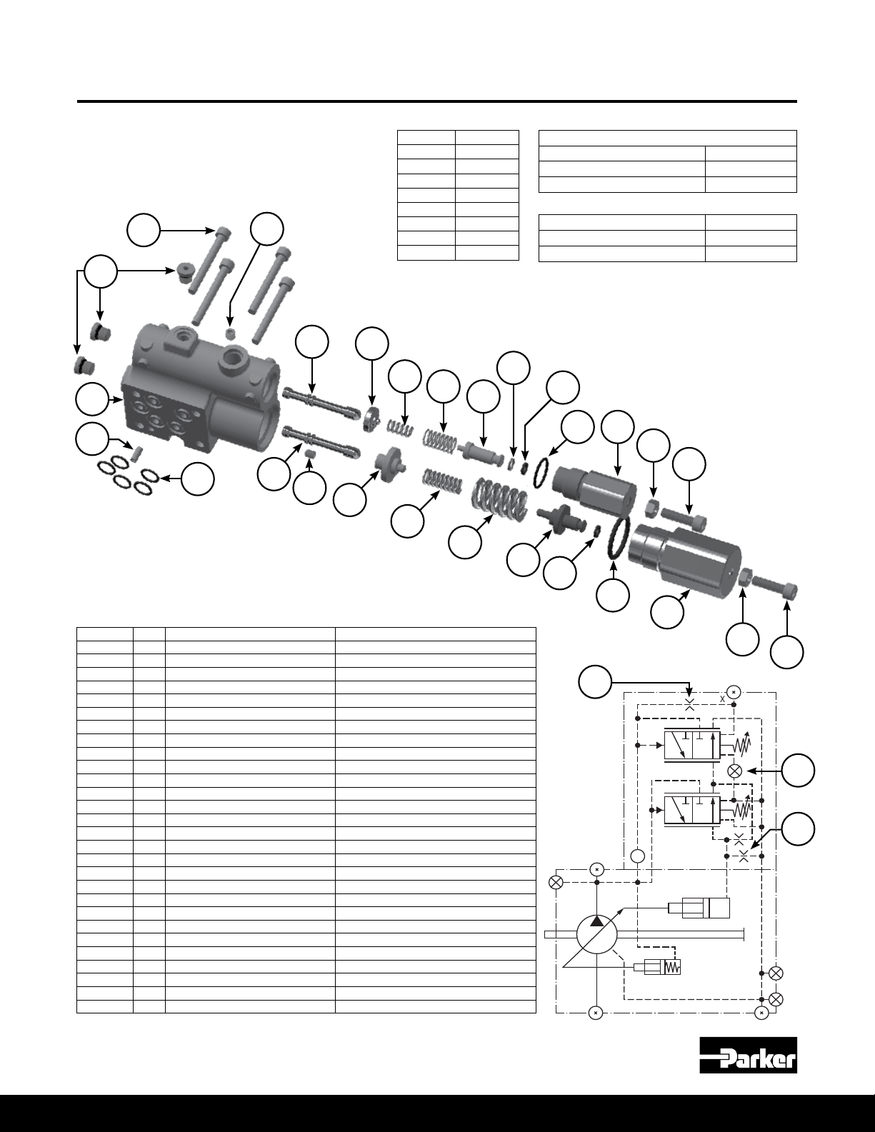
018, 028 B-mod Pump Exploded View
* Clockwise Rotation Shown
5
7
16
8
14
15
Medium Pressure Axial Piston Pumps
P1/PD B-mod Service Information
36
1
2
12
13
11
4
27
20
17
18
19
22
23
9
21
24
25
2930
26
34
36
35
Item
2 52 ft-lbs 52 ft-lbs
3 45 ft-lbs 45 ft-lbs
5 6 ft-lbs 6 ft-lbs
6 25 in-lbs 25 in-lbs
16 12 in-lbs 70 in-lbs
19 45 ft-lbs 45 ft-lbs
30 30 in-lbs 30 in-lbs
34 70 in-lbs 70 in-lbs
36 16 ft-lbs 45 ft-lbs
37 14 ft-lbs 14 ft-lbs
38 70 in-lbs 70 in-lbs
Parker Hannin Corporation
Hydraulic Pump and Power Systems Division
Marysville, Ohio USA
18 28
Torque Torque
28
38
41
37
39
40
7
30
31
32
42
43
46
36
Bulletin HY28-2708-02/SVC/EN | July 2019
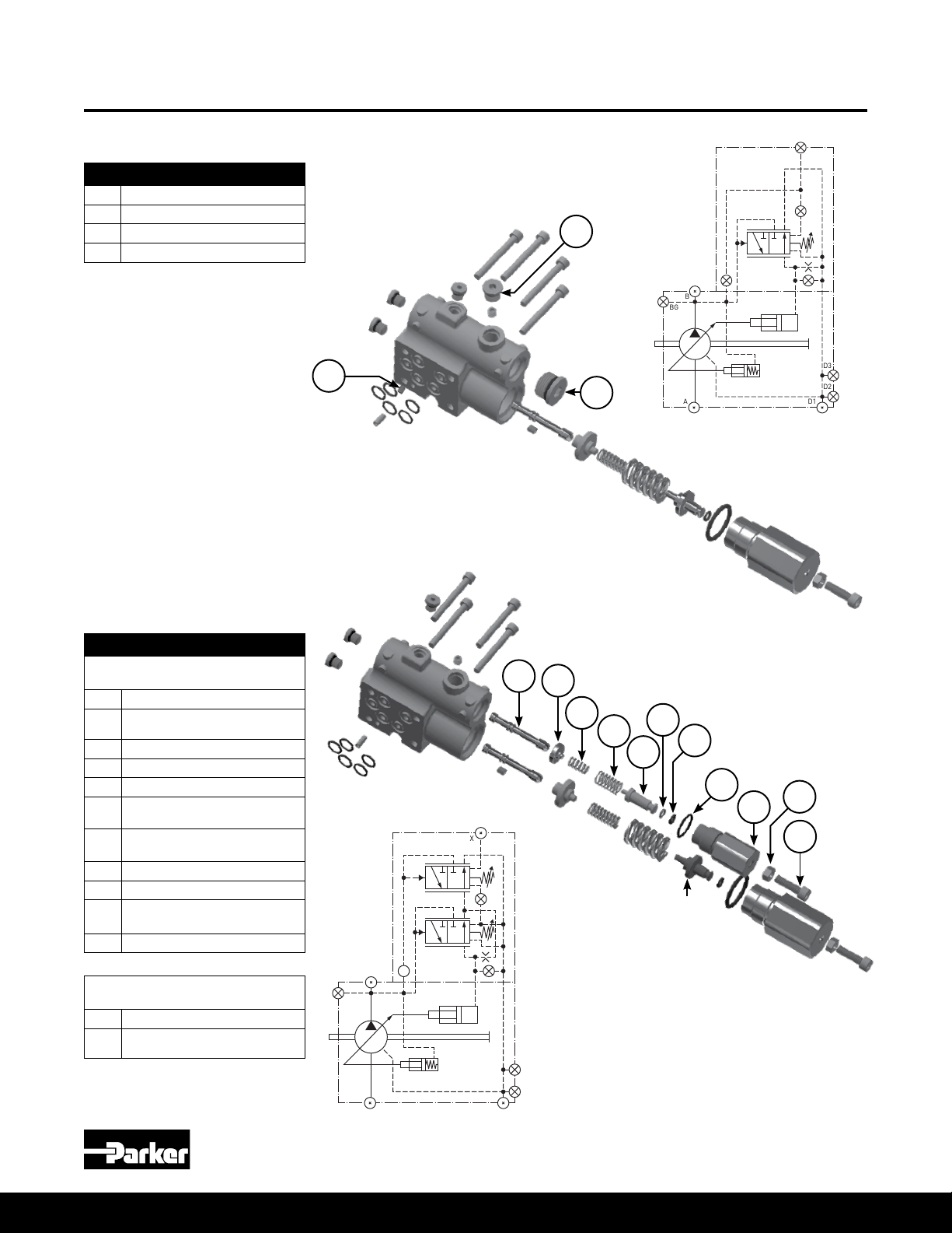
045 B-mod Pump Exploded View
* Clockwise Rotation Shown
7
17
8
10
14
15
9
Medium Pressure Axial Piston Pumps
P1/PD B-mod Service Information
6
3
1
5
2
19
18
16
12
Item
1 63 ft-lbs
2 45 ft-lbs
5 6 ft-lbs
6 25 in-lbs
11 105 ft-lbs
14 105 ft-lbs
16 10 ft-lbs
19 46 ft-lbs
30 30 in-lbs
34 70 in-lbs
36 75 ft-lbs
37 14 ft-lbs
45
Torque
27
13
11
41
40
37
39
10
17
26
4
42
25
36
24
35
23
34
36
30
32
22
31
21
30
20
28
29
Parker Hannin Corporation
Hydraulic Pump and Power Systems Division
8
Marysville, Ohio USA
Bulletin HY28-2708-02/SVC/EN | July 2019
018, 028, 045 Pump Parts
Medium Pressure Axial Piston Pumps
P1/PD B-mod Service Information
Item No Qty 018 Part No 028 Part No 045 Part No Description
1
2* 2 108X8V 108X8V 108X8V Volume stop boss plug & O-ring
3 1 Contact factory for port block ordering information. Port block
4* 1 2050V-7 2160V-7 675-00162-0 Port block O-ring
5* 4 108X2V 108X2V 108X2V Boss plug & O-ring
6 1 226X42 226X42 226X42 M5X6 Control Flow Set Screw
7 1 299X67 324-30014-0 324-30014-0 Port plate pin
8* 3 605-10077-0 605-10077-0 605-10077-0 Control pressure passage o-rings
9*** 1
10* 2 ** ** 695-00912-0 Bias and control rod O-ring
11
12 1 03E-94428-0 03E-94391-0 03E-94354-0 Bias piston
13
14
15 1 03E-94426-0 03E-94389-0 03E-94352-0 Control piston
16 1 226X14 226X56 102x1 Ripple chamber plug (side ported version only)
17 2 299X123 299X123 299X123 Cover dowel pin
18 1 216-10013-0 789814 230-82227-0 Port block bushing
19 1 102X8V 102X8V 108X10V Ripple chamber plug
20 1 256X521 256X525 356-65144-0 Retaining ring, internal
21 1 787635 03E-94387-0 03E-94350-0 Barrel hold down spring
22 2 (1:045) 786996 03E-94388-0 03E-94351-0 Barrel hold down washer
23 1 03E-94717-0 03E-94375-0 03E-94338-0 Barrel
24 3 787000 03E-94386-0 03E-95903-0 Barrel hold down pin
25 1 787002 03E-94385-0 03E-96852-0 Spherical washer
26 1 786994 03E-97011-0 03E-96988-0 Retainer plate
27 9 789641 S2E-18415-0 S2E-18413-0 Piston and shoe assembly
28 1
29 1 S2E-19079-0 S2E-18414-0 S2E-18412-0 Cam
30 2 03E-94359-0 03E-94359-0 03E-94359-0 Bearing retainer screws
31 2 03E-94432-0 03E-94395-0 03E-94358-0 Cam bearing
32 1 230-82515-0 789815 230-82516-0 Cylindrical roller bearing
34 1 226X56 226X56 226X56 M6X6 bias ow set screw
35 1 ** ** ** Housing (not sold separately)
36* 2
37* 1
38* 1 P2-000-3506-08 P2-000-3506-08 ** M6X6 set screw with 0.8mm orice
39* 1 787140 P2-060-3304 620-82125-5 Shaft seal
40 1 256X535 256X544 356-65158-0 Seal retainer
41 1 See separate compensator ordering information Compensator
42 1 256X222 256X222 356-65159-0 External retaining ring (shaft)
43 1 256X544 256X544 ** Internal retaining ring (housing)
* Denotes seal or O-ring is included in the seal kit
Parker Hannin Corporation
Hydraulic Pump and Power Systems Division
Marysville, Ohio USA
4 210x209 210x211 361-12229-0 Socket head cap screws
4 ** 210x209 ** Socket head cap screws (28cc thru drive version only)
03E-94415-0 03E-94969-0 03E-94339-0 Port plate, CW, industrial (PD)
03E-94414-0 03E-94970-0 03E-94340-0 Port plate, CCW, industrial (PD)
03E-94413-0 03E-94969-0 03E-94341-0 Port plate, CW, mobile (P1)
03E-94416-0 03E-94970-0 03E-94342-0 Port plate, CCW, mobile (P1)
03E-94963-0 03E-94376-0 03E-95374-0 Port plate, CW, industrial (PD), ripple chamber
03E-94964-0 03E-94377-0 03E-95080-0 Port plate, CCW, industrial (PD), ripple chamber
03E-94965-0 03E-94378-0 03E-95374-0 Port plate, CW, mobile (P1), ripple chamber
03E-94966-0 03E-94379-0 03E-95375-0 Port plate, CCW, mobile (P1), ripple chamber
1 03E-94427-0 03E-94390-0 03E-94355-0 Bias guide
1 ** ** 03E-95658-0 Bias guide (overcenter option)
1 03E-94430-0 03E-94393-0 03E-94356-0 Bias spring
1 ** ** 03E-95656-0 Bias spring (overcenter option)
1 03E-94427-0 03E-94390-0 03E-94353-0 Control guide
1 ** ** 03E-95657-0 Control guide (overcenter option)
03E-94409-0 03E-97070-0 03E-97070-0 01 shaft option, no thru drive
03E-94411-0 03E-94374-0 03E-94337-0 01 shaft option with thru drive
S2E-19657-0 S2E-19661-0 S2E-19665-0 02 shaft option assembly with key (no thru drive)
S2E-19658-0 S2E-19662-0 S2E-19666-0 02 shaft option assembly (thru drive)
S2E-19659-0 S2E-19663-0 S2E-19667-0 04 shaft option assembly with key (no thru drive)
S2E-19660-0 S2E-19664-0 S2E-19668-0 04 shaft option assembly (thru drive)
03E-94718-0 ** ** 06 shaft option assembly (no thru drive)
03E-96233-0 ** ** 06 shaft option assembly (thru drive)
03E-94804-0 03E-95166-0 03E-94990-0 08 shaft option, (no thru drive)
03E-94762-0 03E-95492-0 03E-95197-0 08 shaft option (thru drive)
108X6V 108X8V 108X10V Case drain plug & O-ring - SAE ORB
788153V 788161V 788161V Case drain plug & O-ring - BSPP
788516-06V 788516-10V 788516-10V Case drain plug & O-ring - ISO
108X4V 108X4V 108X4V BG port plug & O-ring - SAE ORB
789189V 789189V 789189V BG port plug & O-ring - BSPP
788516-04V 788516-04V 788516-04V BG port plug & O-ring - ISO
| *** Contact factory for 045 overcenter "X" port plate part number information
9
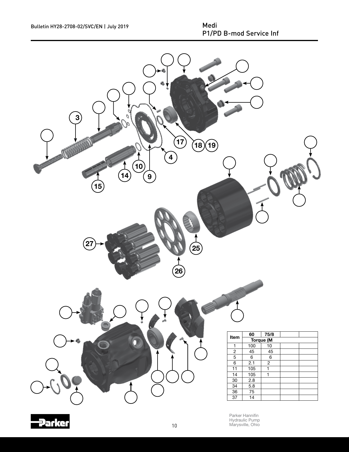
Bulletin HY28-2708-02/SVC/EN | July 2019
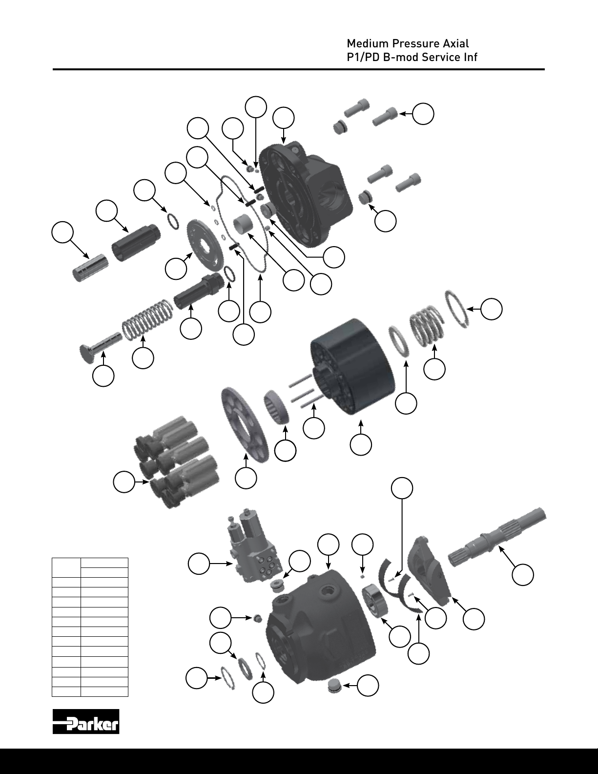
060, 075, 085, 100, 140 B-mod Pump Exploded View
* Counter-clockwise Rotation Shown
36
5
Medium Pressure Axial Piston Pumps
P1/PD B-mod Service Information
16
12
13
27
11
15
10
14
8
7
1
2
10
17
4
18 19
23
22
20
9
21
24
25
40
39
37
41
36
36
35
34
32
33
30
31 30
10
26
29
28
Item
Parker Hannin Corporation
Hydraulic Pump and Power Systems Division
Marysville, Ohio USA
60 75/85 100 140
Torque (Measured in ft-lbs)
1 100 100 170 205
2 45 45 45 45
5 6 6 6 6
6 2.1 2.1 2.1 2.1
11 105 105 136 170
14 105 105 136 170
30 2.8 2.8 2.8 2.8
34 5.8 5.8 5.8 5.8
36 75 85 85 135
37 14 14 14 14
Bulletin HY28-2708-02/SVC/EN | July 2019
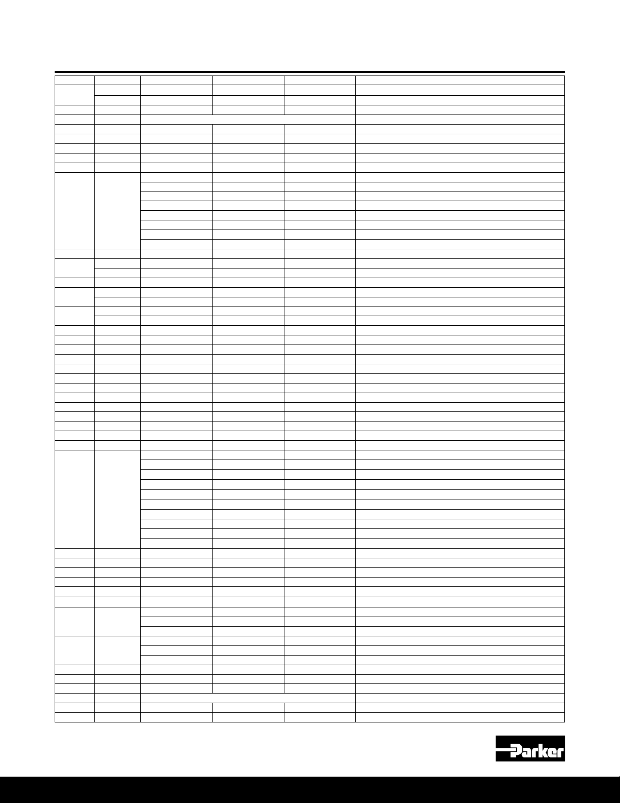
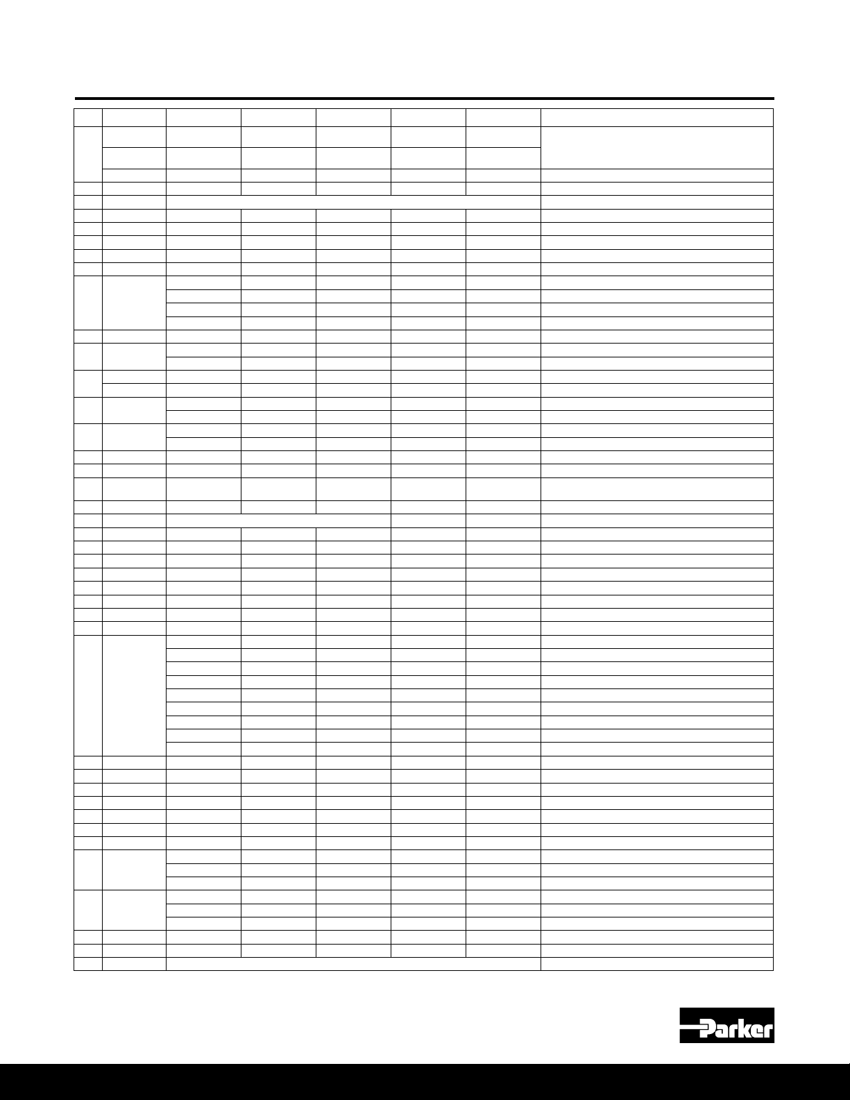
060, 075, 085, 100, 140 Pump Parts
Medium Pressure Axial Piston Pumps
P1/PD B-mod Service Information
Item
No
2* 2 108X8V 108X8V 108X8V 108X8V 108X8V Volume stop boss plug & O-ring
4* 1 675-00164-0 675-00165-0 675-00165-0 675-00169-0 675-00173-0 Port block O-ring
5* 2 108X2V 108X2V 108X2V 108X2V 108X2V Boss plug & O-ring
8* 3 605-10070-0 605-10070-0 605-10070-0 605-10070-0 605-10070-0 Control pressure O-rings
9*** 1
10* 2 695-00912-0 695-00912-0 695-00912-0 695-00914-0 695-00916-0 Bias and control rod O-ring
11 1
12
13 1
14 1
15 1 03E-94051-0 03E-93147-0 03E-93147-0 03E-93797-0 03E-94751-0 Control piston
16* 2 108X4V 108X4V 108X4V 108X4V 108X4V Boss plug & O-ring
17 1 S2E-18591-0K S2E-18591-0K S2E-18591-0K S2E-18640-0K S2E-18527-0K
18 1 230-82237-0 230-82237-0 230-82237-0 230-82244-0 230-82239-0 Tapered roller bearing cup
19 1 INCLUDED IN ITEM 18 230-82518-0
20 1 356-65152-0 356-65144-0 356-65144-0 356-65146-0 356-65147-0 Retaining ring, internal
21 1 03E-94049-0 03E-93145-0 03E-93145-0 03E-93795-0 03E-93959-0 Barrel hold down spring
22 1 03E-94050-0 03E-93146-0 03E-93146-0 03E-93796-0 03E-93244-0 Barrel hold down washer
23 1 03E-94036-0 03E-93129-0 03E-95465-0 03E-95603-0 03E-93242-0 Barrel
24 3 03E-95904-0 03E-95905-0 03E-95905-0 03E-95906-0 03E-95907-0 Barrel hold down pin
25 1 03E-94047-0 03E-93142-0 03E-93142-0 03E-93794-0 03E-93241-0 Spherical washer
26 1 03E-97012-0 03E-93139-0 03E-95501-0 03E-93793-0 03E-93240-0 Retainer plate
27 9 S2E-18296-0 S2E-17003-0 S2E-19330-0 S2E-17912-0 S2E-17323-0 Piston and shoe assembly
28 1
29 1 S2E-18411-0 S2E-17443-0 S2E-17443-0 S2E-17961-0 S2E-17957-0 Cam
30 2 03E-93763-0 03E-93763-0 03E-93763-0 03E-93763-0 03E-93763-0 Bearing retainer screws
31 2 03E-94057-0 03E-93950-0 03E-93950-0 03E-93952-0 03E-93953-0 Cam bearing
32 1 230-82236-0 230-82236-0 230-82236-0 230-82519-0 230-82241-0 Tapered roller bearing cone (and cup 140)
33 1 230-82235-0 230-82235-0 230-82235-0 230-82245-0 ** Tapered roller bearing cup
34 1 226X56 226X56 226X56 226X56 226X56 M6X6 bias ow set screw
35 1 ** ** ** ** ** Housing (not sold separately)
36* 2
37* 1
39* 1 620-82118-5 620-82118-5 620-82118-5 620-82121-5 620-82120-5 Shaft seal
40 1 356-65146-0 356-65146-0 356-65146-0 356-65147-0 356-65148-0 Seal retainer
41 1 See separate compensator ordering information. Compensator
Qty 060 Part No 075 Part No 085 Part No 100 Part No 140 Part No Description
4
(2: 075/085)
0
1
(2: 075/085)
4 361-13250-0 361-13250-0 361-13250-0 361-14290-0 361-15267-0 Socket head cap screws (thru drive version only)
3 1 Contact factory for port block ordering information. Port block
6 1 226X42 226X42 226X42 226X42 226X42 M5X6 control ow set screw
7 1 324-30014-0 324-30014-0 324-30014-0 324-30014-0 324-30014-0 Port plate pin
1 03E-94053-0 03E-93149-0 03E-93149-0 03E-93799-0 03E-94658-0 Bias piston
1 03E-94835-0 03E-93149-0 ** 03E-93799-0 03E-94658-0 Bias piston (overcenter option "X")
361-13250-0 361-13270-0 361-13270-0 361-14290-0 361-15270-0
361-13250-0 361-13250-0 361-13250-0 361-14290-0 361-15270-0
03E-94038-0 03E-93169-0 03E-93169-0 03E-95605-0 03E-93252-0 Port plate, CW, industrial (PD)
03E-94039-0 03E-93170-0 03E-93170-0 03E-95606-0 03E-93253-0 Port plate, CCW, industrial (PD)
03E-94040-0 03E-93171-0 03E-93171-0 03E-95607-0 03E-93254-0 Port plate, CW, mobile (P1)
03E-94041-0 03E-93172-0 03E-93172-0 03E-95608-0 03E-93255-0 Port plate, CCW, mobile (P1)
03E-94054-0 03E-93150-0 03E-93150-0 03E-93800-0 03E-93248-0 Bias guide
03E-94832-0 03E-94498-0 ** 03E-94827-0 03E-94743-0 Bias guide (overcenter option “X”)
03E-94055-0 03E-93151-0 03E-93151-0 03E-93801-0 03E-93963-0 Bias spring
03E-94834-0 03E-94499-0 ** 03E-94829-0 03E-94752-0 Bias spring (overcenter option “X”)
03E-94052-0 03E-93148-0 03E-95471-0 03E-93798-0 03E-97335-0 Control guide
03E-94833-0 03E-94608-0 ** 03E-94828-0 03E-93246-0 Control guide (overcenter option “X”)
INCLUDED IN ITEM 18
03E-94032-0 03E-97070-0 03E-97070-0 03E-93779-0 03E-93227-0 01 shaft, no thru drive
03E-94033-0 03E-94000-0 03E-94000-0 03E-93780-0 03E-93228-0 01 shaft with thru drive
S2E-19669-0 S2E-19673-0 S2E-19673-0 S2E-19677-0 S2E-19681-0 02 shaft assembly with key (no thru drive)
S2E-19670-0 S2E-19674-0 S2E-19674-0 S2E-19678-0 S2E-19682-0 02 shaft assembly (thru drive)
S2E-19671-0 S2E-19675-0 S2E-19675-0 S2E-19679-0 S2E-19683-0 04 shaft assembly with key (no thru drive)
S2E-19672-0 S2E-19676-0 S2E-19676-0 S2E-19680-0 S2E-19684-0 04 shaft assembly (thru drive)
03E-95611-0 ** ** 03E94500-0 ** 06 (100cc) & 09 (60cc) shaft, no thru drive
03E-96177-0 ** ** 03E-94462-0 ** 06 (100cc) & 09 (60cc) shaft, thru drive
03E-96216-0 ** ** ** ** 10 shaft, no thru drive
108X10V 108X12V 108X12V
788175V 788175V 788175V 788175V 447-00038-5 Case drain plug & O-ring - BSPP
788516-10V 788516-12V 788516-12V 788516-12V 788516-16V Case drain plug & O-ring - ISO
108X4V 108X4V 108X4V 108X4V 108X4V BG port plug & O-ring - SAE ORB
789189V 789189V 789189V 789189V 789189V BG port plug & O-ring - BSPP
788516-04V 788516-04V 788516-04V 788516-04V 788516-04V BG port plug & O-ring - ISO
108X12V 108X16V Case drain plug & O-ring - SAE ORB
Socket head cap screws (non-thru drive version)
Bearing shim kit (includes all standard shim
sizes)
Tapered roller bearing cone
* Denotes seal or O-ring is included in the seal kit | *** Contact factory for overcenter "X" port plate part number information
Parker Hannin Corporation
Hydraulic Pump and Power Systems Division
Marysville, Ohio USA
11
Bulletin HY28-2708-02/SVC/EN | July 2019
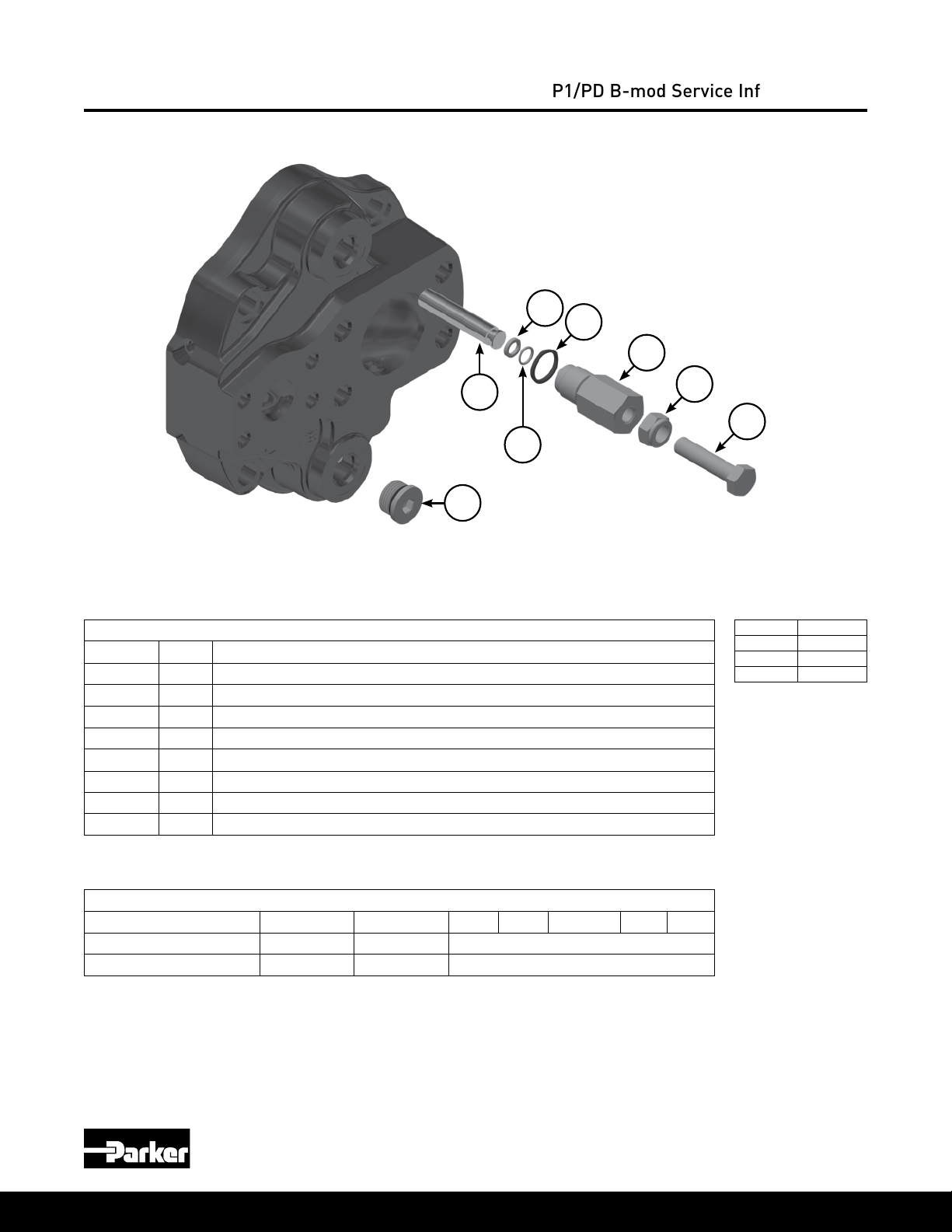
Volume Stop Control
Medium Pressure Axial Piston Pumps
P1/PD B-mod Service Information
59
57
56
60
58
2
NOTE: Picture shows max volume stop location for counter-clockwise rotation and min volume stop
location for clockwise rotation. Plug and stop assembly locations would be switched for opposite rotation.
Volume Stop Parts
Item No Qty Description
2 1 Plug with O-ring (no volume stop)
54 1 Adjusting screw
55 1 Adjusting screw lock nut
56 1 Volume stop plug
57 1 Volume stop plug O-ring
58 1 Backup ring
59 1 Volume stop rod O-ring
60* 1 Volume stop rod
*Min & max rods same for the 45 thru 140, but different on the 18 & 28. See table below for kit part number.
55
54
Item Torque
2 45 ft-lbs
55 18 ft-lbs
56 45 ft-lbs
Volume Stop Kits
Size 018 028 045 060 075/085 100 140
Maximum volume stop kit S2E-19203-5K S2E-19204-5K S2E-19115-5K
Minimum volume stop kit S2E-19608-5K S2E-19609-5K S2E-19115-5K
Parker Hannin Corporation
Hydraulic Pump and Power Systems Division
12
Marysville, Ohio USA
Bulletin HY28-2708-02/SVC/EN | July 2019
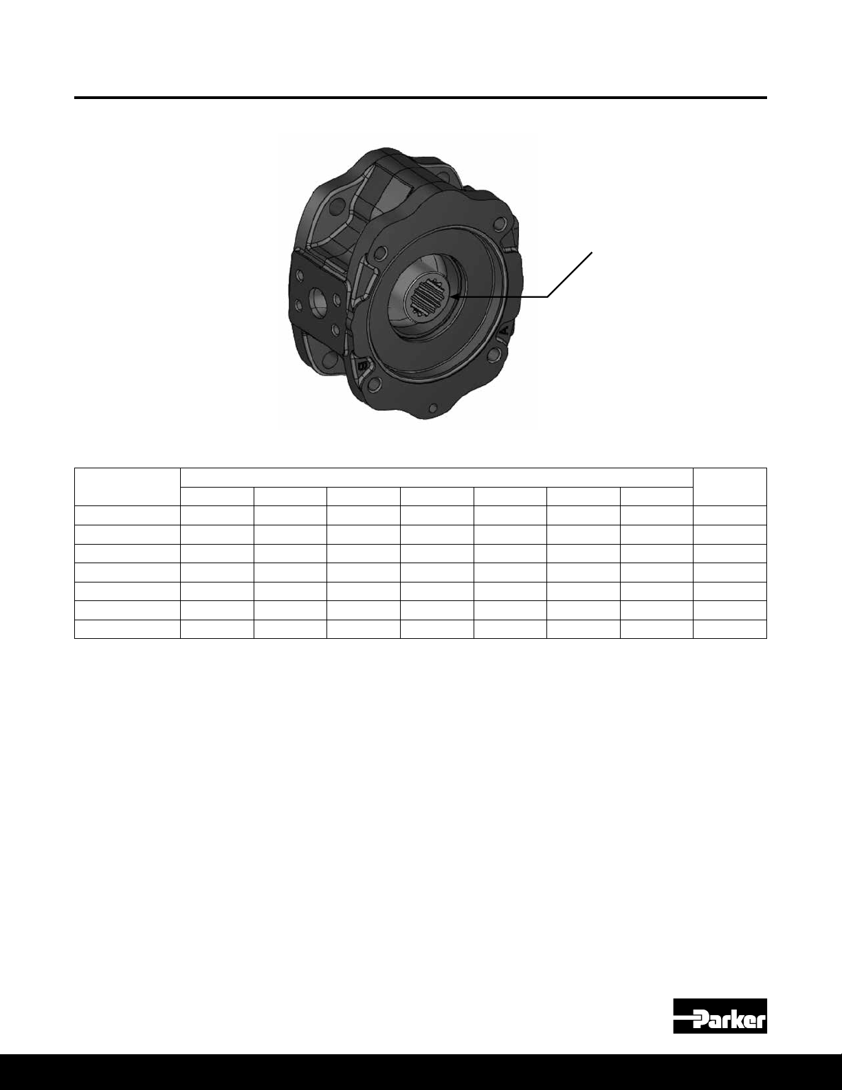
Thru Drive Couplings and O-rings
Medium Pressure Axial Piston Pumps
P1/PD B-mod Service Information
Thru Drive
Pad Coupling
Thru Drive
Pad Coupling
SAE A, 9 Tooth S2E-19538-0 S2E-19364-0 03E-94942-0 03E-93278-0 03E-93278-0 03E-94274-0 03E-93947-0 695-00237-0
SAE A, 11 Tooth S2E-19726-0 S2E-19391-0 03E-94943-0 03E-94724-0 03E-94724-0 03E-94657-0 03E-95706-0 695-00237-0
SAE B, 13 Tooth ** S2E-19365-0 03E-94945-0 03E-93277-0 03E-93277-0 03E-94273-0 03E-93946-0 695-00243-0
SAE BB, 15 Tooth ** S2E-19409-0 03E-94361-0 03E-93279-0 03E-93279-0 03E-94272-0 03E-93945-0 695-00243-0
SAE C, 14 Tooth ** ** ** 03E-93276-0 03E-93276-0 03E-94271-0 03E-93944-0 695-00251-0
SAE CC, 17 Tooth ** ** ** ** ** 03E-94270-0 03E-93943-0 695-00251-0
SAE D&E, 13 Tooth ** ** ** ** ** ** 03E-93942-0 695-00259-0
018 028 045 060 075/085 100 140
Thru Drive Couplings
O-ring
Parker Hannin Corporation
Hydraulic Pump and Power Systems Division
Marysville, Ohio USA
13
Bulletin HY28-2708-02/SVC/EN | July 2019
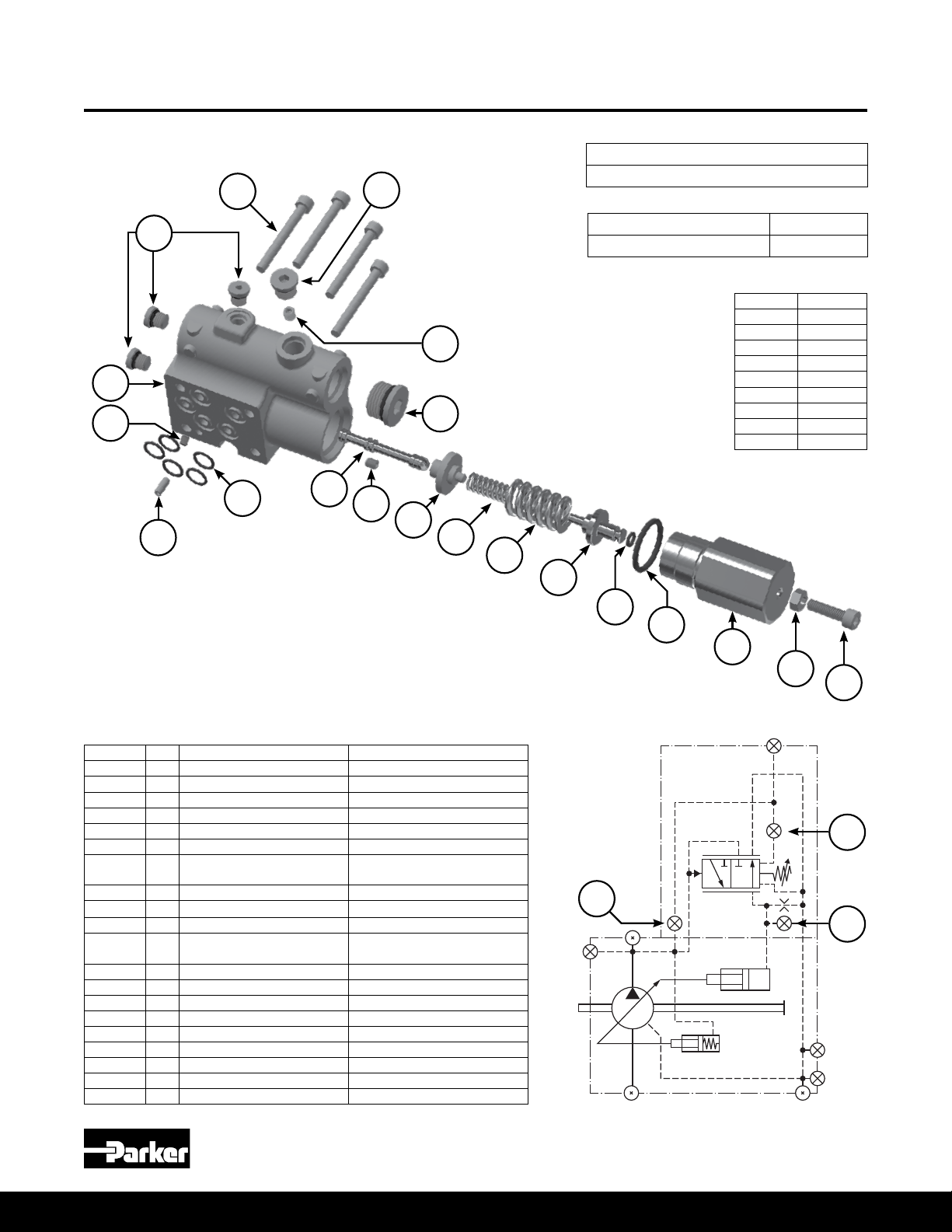
C0 B-mod Control Exploded View
12
Medium Pressure Axial Piston Pumps
P1/PD B-mod Service Information
C0 Controller Assembly Part Number
S2E-20171-5T
18
31
17
13
15
14
Pmax Spool Kit* S2E-20821-5K
Seal Kit (C, L, & AM controls) S2E-20363-5K
* Includes items 1-11, 16 & 17
Item Torque
2 30 in-lbs
16
19
9 85 ft-lbs
10 70 in-lbs
12 45 in-lbs
13 35 in-lbs
16 40 in-lbs
17 12 in-lbs
18 11 ft-lbs
19 50 ft-lbs
1
2
3
4
5
6
7
8
9
10
11
Item Qty Part Number Description
1 1 03E-95926-0 Pmax spool
2 1 226X42 M5 x 6 set screw
3 1 Available in kit only Pmax inner spring guide
4 1 Available in kit only Pmax inner spring
5 1 Available in kit only Pmax outer spring
6 1 Available in kit only Pmax outer spring guide
7* 1 Available in kit only
8* 1 Available in kit only Pmax main O-ring
9 1 03E-95570-0 Pmax outer cap
10 1 340-00063-0 Pmax adjustment lock nut
11 1 361-08275-0
12 4 361-07253-8 M5 x 45 SHCS
13* 3 108X2V SAE Boss Plug & O-ring
14* 5 Available in kit only Compensator teon O-ring
15 1 325-36001-0 Compensator M4 x 10 roll pin
16 1 226X56 M6 x 6 set screw
17 1 226X26 M4 x 5 set screw
18 1 108X4V Boss plug & O-ring - SAE
19 1 108X8V Boss plug & O-ring
31 1 Not sold separately Compensator housing
*Included in C, L, & AM controls seal kit
Pmax outer spring guide
O-ring
Pmax M6x22 adjustment
screw
14
X
16
17
2
B
BG
D3
D2
D1A
Parker Hannin Corporation
Hydraulic Pump and Power Systems Division
Marysville, Ohio USA

Bulletin HY28-2708-02/SVC/EN | July 2019
X
B
BG
D3
D2
D1A
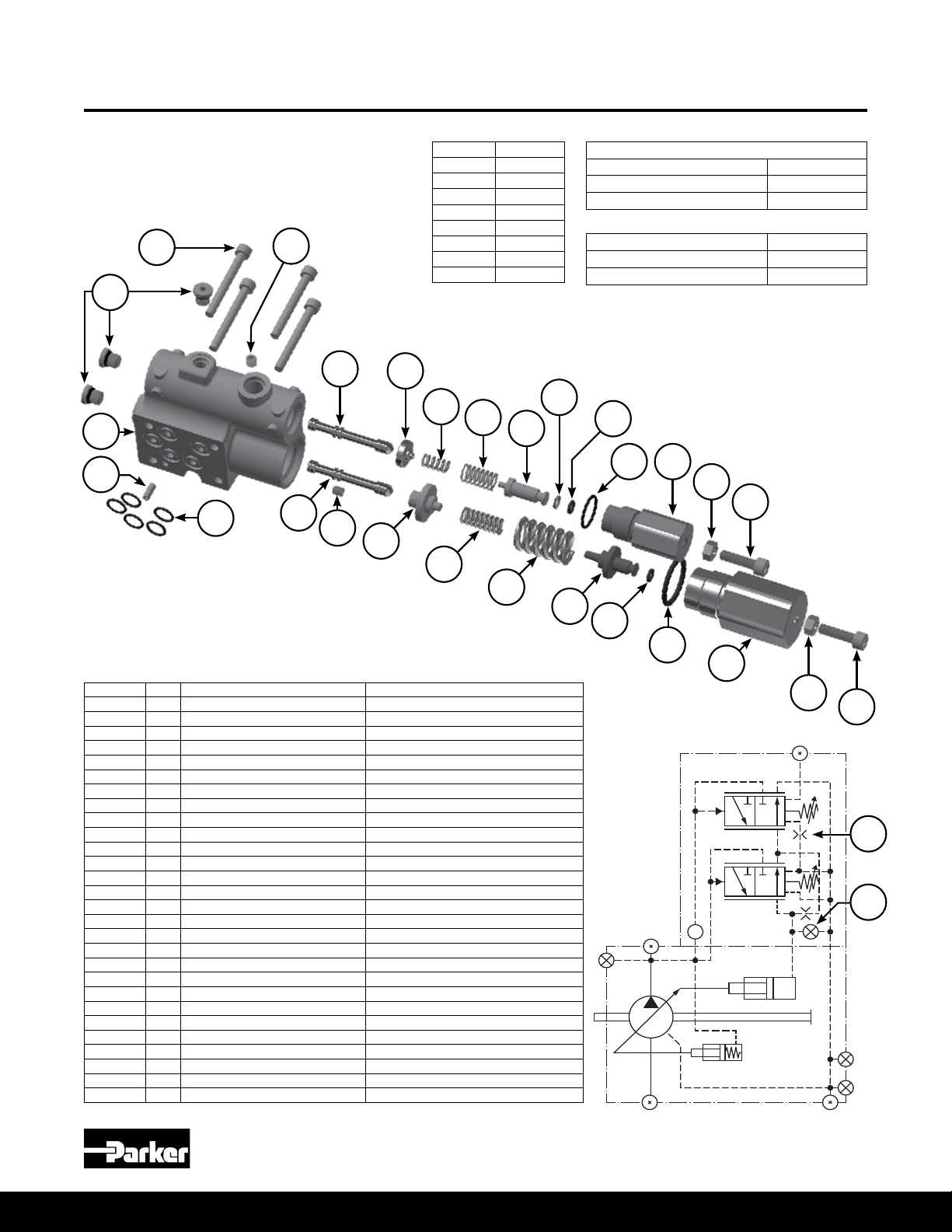
L0 B-mod Control Exploded View
Medium Pressure Axial Piston Pumps
P1/PD B-mod Service Information
13
31
15
12
14
16
Item Torque
2 30 in-lbs
9 85 ft-lbs
10 70 in-lbs
12 45 in-lbs
13 35 in-lbs
16 40 in-lbs
28 50 ft-lbs
29 70 in-lbs
20
21
22
23
25
24
1
2
L0 Controller Assembly Part Numbers
SAE* S2E-19440-5T
Metric* S2E-20186-5T
BSPP* S2E-20189-5T
* Designates load sense port thread type
Pmax Spool Kit** S2E-20821-5K
Load Sense Spool Kit*** S2E-20822-5K
Seal Kit (C, L, & AM controls) S2E-20363-5K
** Includes items 1-11, 16 & 17
*** Includes items 2, 16, 20-30
26
28
27
29
30
3
4
5
6
7
8
9
Item Qty Part Number Description
1 1 03E-95926-0 Pmax spool
2 1 226X42 M5 x 6 set screw
3 1 Available in kit only Pmax inner spring guide
4 1 Available in kit only Pmax inner spring
5 1 Available in kit only Pmax outer spring
6 1 Available in kit only Pmax outer spring guide
7* 1 Available in kit only Pmax outer spring guide O-ring
8* 1 Available in kit only Pmax main O-ring
9 1 03E-95570-0 Pmax outer cap
10 1 340-00063-0 Pmax adjustment lock nut
11 1 361-08275-0 Pmax M6x22 adjustment screw
12 4 361-07253-8 M5 x 45 SHCS
13* 3 108X2V SAE Boss Plug & O-ring
14* 5 Available in kit only Compensator teon O-ring
15 1 325-36001-0 Compensator M4 x 10 roll pin
16 1 226X56 M6 x 6 set screw
20 1 03E-95926-0 Differential spool
21 1 Available in kit only Differential inner spring guide
22 1 Available in kit only Differential inner spring
23 1 Available in kit only Differential outer spring
24 1 Available in kit only Differential outer spring guide
25* 1 Available in kit only Differential inner spring guide O-ring
26* 1 Available in kit only Differential inner spring guide O-ring
27* 1 Available in kit only Differential main O-ring
28 1 03E-95572-0 Differential outer cap
29 1 340-00063-0 Differential adjustment lock nut
30 1 361-08275-0 Differential M6x22 adjustment screw
31 1 Not sold separately Compensator housing
*Included in C, L, & AM controls seal kit
Parker Hannin Corporation
Hydraulic Pump and Power Systems Division
Marysville, Ohio USA
15
10
11
16
2
Bulletin HY28-2708-02/SVC/EN | July 2019
X
B
BG
D3
D2
D1A
L2 B-mod Control Exploded View
Medium Pressure Axial Piston Pumps
P1/PD B-mod Service Information
13
31
15
12
14
16
Item Torque
2 30 in-lbs
9 85 ft-lbs
10 70 in-lbs
12 45 in-lbs
13 35 in-lbs
16 40 in-lbs
28 50 ft-lbs
29 70 in-lbs
20
21
22
23
25
24
1
2
L2 Controller Assembly Part Numbers
SAE* S2E-20196-5T
Metric* S2E-20187-5T
BSPP* S2E-20190-5T
* Designates load sense port thread type
Pmax Spool Kit** S2E-20821-5K
Load Sense Spool Kit*** S2E-20822-5K
Seal Kit (C, L, & AM controls) S2E-20363-5K
** Includes items 1-11, 16 & 17
*** Includes items 2, 16, 20-30
26
28
27
29
30
3
4
5
6
7
8
9
Item Qty Part Number Description
1 1 03E-95926-0 Pmax spool
2 1 226X42 M5 x 6 set screw
3 1 Available in kit only Pmax inner spring guide
4 1 Available in kit only Pmax inner spring
5 1 Available in kit only Pmax outer spring
6 1 Available in kit only Pmax outer spring guide
7* 1 Available in kit only Pmax outer spring guide O-ring
8* 1 Available in kit only Pmax main O-ring
9 1 03E-95570-0 Pmax outer cap
10 1 340-00063-0 Pmax adjustment lock nut
11 1 361-08275-0 Pmax M6x22 adjustment screw
12 4 361-07253-8 M5 x 45 SHCS
13* 3 108X2V SAE Boss Plug & O-ring
14* 5 Available in kit only Compensator teon O-ring
15 1 325-36001-0 Compensator M4 x 10 roll pin
16 1 P2-000-3506-04 M6 x 6 set screw with 0.4mm orice
20 1 03E-95926-0 Differential spool
21 1 Available in kit only Differential inner spring guide
22 1 Available in kit only Differential inner spring
23 1 Available in kit only Differential outer spring
24 1 Available in kit only Differential outer spring guide
25* 1 Available in kit only Differential inner spring guide O-ring
26* 1 Available in kit only Differential inner spring guide O-ring
27* 1 Available in kit only Differential main O-ring
28 1 03E-95572-0 Differential outer cap
29 1 340-00063-0 Differential adjustment lock nut
30 1 361-08275-0 Differential M6x22 adjustment screw
31 1 Not sold separately Compensator housing
*Included in C, L, & AM controls seal kit
Parker Hannin Corporation
Hydraulic Pump and Power Systems Division
16
Marysville, Ohio USA
10
11
16
2
Bulletin HY28-2708-02/SVC/EN | July 2019
X
B
BG
D3
D2
D1A
AM B-mod Control Exploded View
Medium Pressure Axial Piston Pumps
P1/PD B-mod Service Information
13
31
15
12
14
16
Item Torque
2 30 in-lbs
9 85 ft-lbs
10 70 in-lbs
12 45 in-lbs
13 35 in-lbs
16 40 in-lbs
28 50 ft-lbs
29 70 in-lbs
20
21
22
23
25
24
1
2
AM Controller Assembly Part Numbers
SAE* S2E-20172-5T
Metric* S2E-20188-5T
BSPP* S2E-20191-5T
* Designates remote port thread type
Pmax Spool Kit** S2E-20821-5K
AM Spool Kit*** S2E-20823-5K
Seal Kit (C, L, & AM controls) S2E-20363-5K
** Includes items 1-11, 16 & 17
*** Includes items 2, 16, 20-30
26
28
27
29
30
3
4
5
6
7
8
9
Item Qty Part Number Description
1 1 03E-95926-0 Pmax spool
2 1 03E-93269-0 M5 x 6 set screw with 0.8mm orice
3 1 Available in kit only Pmax inner spring guide
4 1 Available in kit only Pmax inner spring
5 1 Available in kit only Pmax outer spring
6 1 Available in kit only Pmax outer spring guide
7* 1 Available in kit only Pmax outer spring guide O-ring
8* 1 Available in kit only Pmax main O-ring
9 1 03E-95570-0 Pmax outer cap
10 1 340-00063-0 Pmax adjustment lock nut
11 1 361-08275-0 Pmax M6x22 adjustment screw
12 4 361-07253-8 M5 x 45 SHCS
13* 3 108X2V SAE Boss Plug & O-ring
14* 5 Available in kit only Compensator teon O-ring
15 1 325-36001-0 Compensator M4 x 10 roll pin
16 1 226X56 M6 x 6 set screw
20 1 03E-95860-0 Differential spool
21 1 Available in kit only Differential inner spring guide
22 1 Available in kit only Differential inner spring
23 1 Available in kit only Differential outer spring
24 1 Available in kit only Differential outer spring guide
25* 1 Available in kit only Differential inner spring guide O-ring
26* 1 Available in kit only Differential inner spring guide O-ring
27* 1 Available in kit only Differential main O-ring
28 1 03E-95572-0 Differential outer cap
29 1 340-00063-0 Differential adjustment lock nut
30 1 361-08275-0 Differential M6x22 adjustment screw
31 1 Not sold separately Compensator housing
*Included in C, L, & AM controls seal kit
Parker Hannin Corporation
Hydraulic Pump and Power Systems Division
Marysville, Ohio USA
17
20
10
11
16
2
Bulletin HY28-2708-02/SVC/EN | July 2019
C0 to L0 B-mod Conversion Guide
Medium Pressure Axial Piston Pumps
P1/PD B-mod Service Information
C0
Remove
Item Description
17 M4 x 5 set screw
18 Boss plug & O-ring - SAE
19 Boss plug & O-ring
17
18
19
X
B
BG
D3
D2
D1A
L0
Add
Kit #1
S2E-20463-5K
Item Description
21 Differential inner spring guide
22 Differential inner spring
23 Differential outer spring
24 Differential outer spring guide
Differential inner spring guide
25
O-ring
Differential inner spring guide
26
O-ring
27 Differential main O-ring
28 Differential outer plug
29 Differential adjustment lock nut
30 Differential adjustment screw
Kit #4
S2E-20466-5K
Item Description
20 Load sense differential spool
20
21
22
23
X
B
BG
D3
D2
D1A
24
25
26
27
28
29
30
18
Parker Hannin Corporation
Hydraulic Pump and Power Systems Division
Marysville, Ohio USA
 Loading...