

Page 1
P1/PD Series: B-Mod Service Information
Medium Pressure Axial Piston Pumps
Bulletin HY28-2708-02/SVC/EN
Effective: July 2019 Replaces: March 29, 2019
Page 2

Bulletin HY28-2708-02/SVC/EN | July 2019
Contents
Medium Pressure Axial Piston Pumps
P1/PD B-mod Service Information
Contents
B-Mod Pump Identication ..................................................................................................................................... 3
B-Mod Controls vs A-mod Controls ........................................................................................................................ 4
General Information ................................................................................................................................................. 5
Typical Characteristics ............................................................................................................................................ 6
Parts Data
018, 028 B-mod Pump Exploded View ................................................................................................................... 7
045 B-mod Pump Exploded View ........................................................................................................................... 8
018, 028, 045 B-mod Pump Parts .......................................................................................................................... 9
060, 075, 085, 100, 140 B-mod Pump Exploded View ......................................................................................... 10
060, 075, 085, 100, 140 B-mod Pump Parts ........................................................................................................ 11
Volume Stop Control ............................................................................................................................................. 12
Thru Drive Couplings and O-rings ......................................................................................................................... 13
C0 B-mod Control Exploded View ........................................................................................................................ 14
L0 B-mod Control Exploded View ......................................................................................................................... 15
L2 B-mod Control Exploded View ......................................................................................................................... 16
AM B-mod Control Exploded View ....................................................................................................................... 17
C0 to L0 B-mod Conversion Guide ....................................................................................................................... 18
C0 to L2 B-mod Conversion Guide ....................................................................................................................... 19
C0 to AM B-mod Conversion Guide ..................................................................................................................... 20
L0 / L2 to C0 B-mod Conversion Guide .............................................................................................................. 21
L0 to L2 B-mod Conversion Guide ....................................................................................................................... 22
L2 to L0 B-mod Conversion Guide ....................................................................................................................... 23
L0 to AM B-mod Conversion Guide ...................................................................................................................... 24
L2 to AM B-mod Conversion Guide ...................................................................................................................... 25
AM to C0 B-mod Conversion Guide ..................................................................................................................... 26
AM to L0 B-mod Conversion Guide ...................................................................................................................... 27
AM to L2 B-mod Conversion Guide ...................................................................................................................... 28
075, 085, 100, 140 Torque Limiter ......................................................................................................................... 29
Electronic Unload Control B-mod Exploded View ................................................................................................ 30
Parts Kits ............................................................................................................................................................... 32
Assembly/Disassembly information
Compensator Procedures ..................................................................................................................................... 33
Pump Service Procedures ..................................................................................................................................... 35
Pump Inspection Procedures ................................................................................................................................ 37
Component Rework Limits .................................................................................................................................... 38
018, 028, 045 Assembly Procedures .................................................................................................................... 39
060, 075, 085, 100, 140 Assembly Procedures .................................................................................................... 43
Assembly Tools ..................................................................................................................................................... 47
Rotation Change ................................................................................................................................................... 51
Test Procedure ...................................................................................................................................................... 53
Test Criteria & Start-up Procedures....................................................................................................................... 55
Trouble Shooting ................................................................................................................................................... 56
Conversions and Formulas ................................................................................................................................... 58
Warning ................................................................................................................................................................. 59
Parker Hannin Corporation
Hydraulic Pump and Power Systems Division
2
Marysville, Ohio USA
Page 3
Bulletin HY28-2708-02/SVC/EN | July 2019
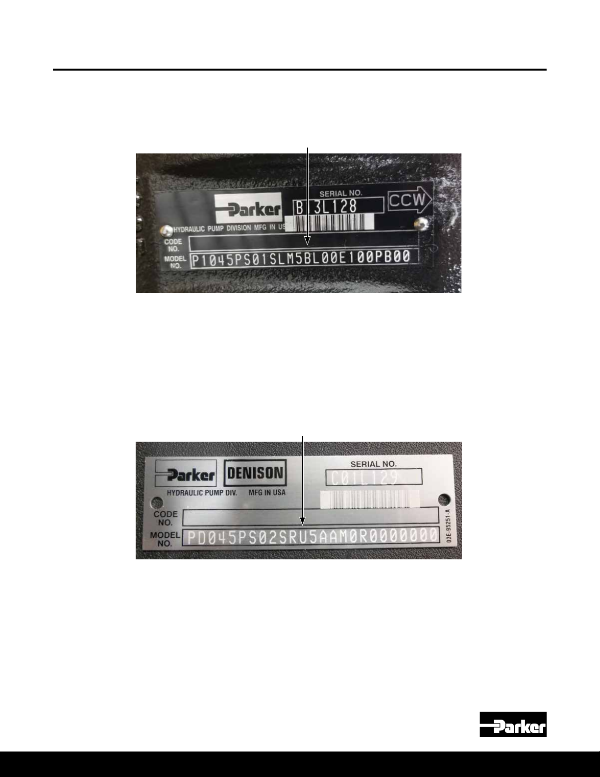
B-Mod Pump Identification
This service manual is to be used for P1/PD Design Series B (B-mod) pumps.
In order to identify which series of pump you have, please refer to the Series
Designation spot in the P1/PD model code as shown below.
The design series is based on the type of control selected. B-mod pumps use
the C, L, and AM controls. All other control types are Design Series A (A-mod).
There are however two exceptions. Both exceptions are on the 45 & 60cc pumps.
One exception is when the load sense (L) or remote compensator (AM) is used
in combination with the torque limiting control (ALT or AMT). The ALT or AMT on
the 45 & 60cc pumps is still the A-mod design series. The other exception is if
the Universal “U” conguration model code option is selected with the 45 or 60cc
pump. On those two displacements, the Universal “U” option is also still an A-mod
design series.
Medium Pressure Axial Piston Pumps
P1/PD B-mod Service Information
Design Series Designation
"U" Universal Designation
For service information on A-mod pumps please refer to
Bulletin HY28-2665-02/SVC/EN. The latest edition can be found at
www.parker.com/HPS.
NOTE: A-mod and B-mod controls are NOT Interchangeable! Adapter block
is required to put a B-mod control on an A-mod or an A-mod control on a
B-mod pump. See Parts Kits page for adapter block part numbers.
Parker Hannin Corporation
Hydraulic Pump and Power Systems Division
Marysville, Ohio USA
3
Page 4
Bulletin HY28-2708-02/SVC/EN | July 2019
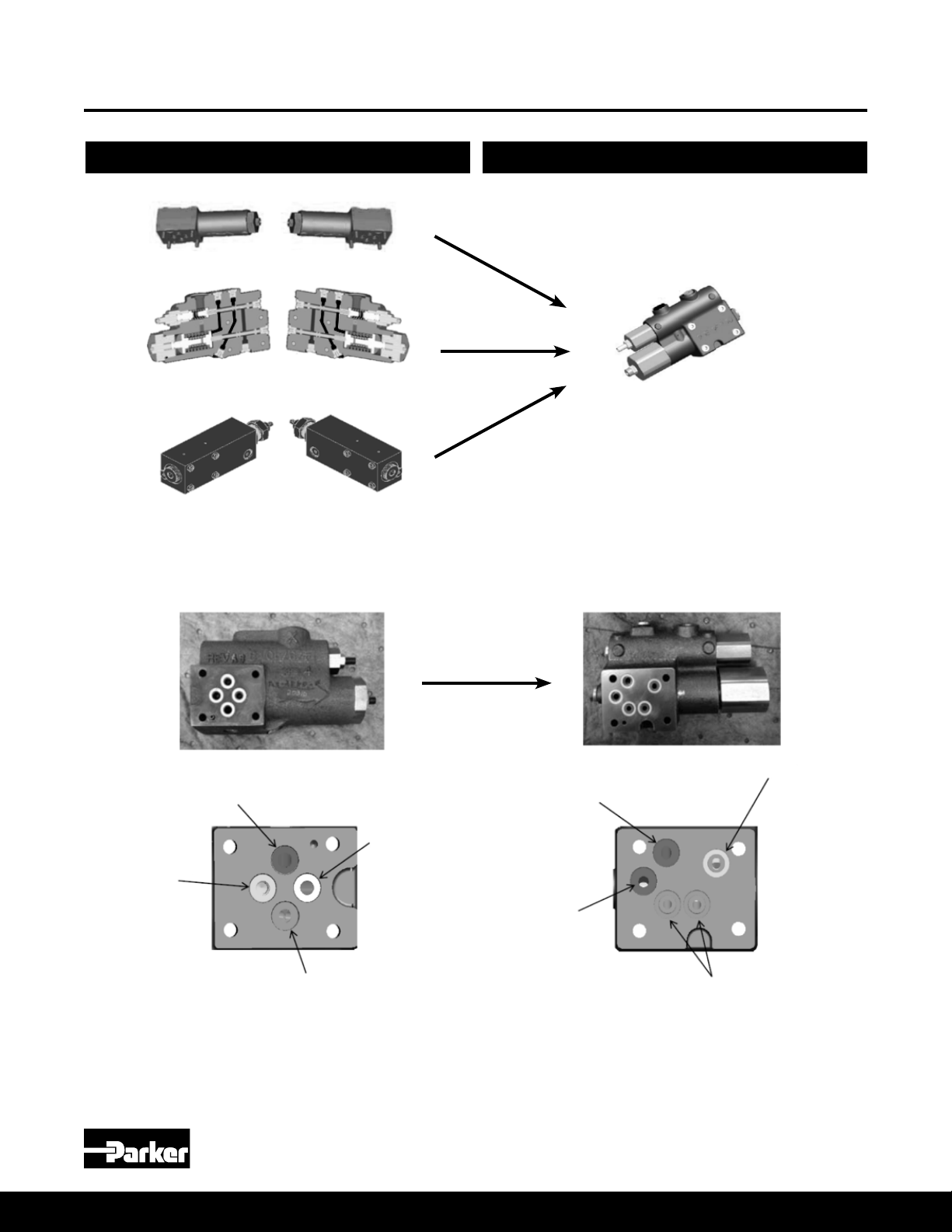
B-Mod Controls vs A-mod Controls
Design Series A Design Series B
Medium Pressure Axial Piston Pumps
P1/PD B-mod Service Information
Pressure Limiter:
C00, C10 (Left)
Pressure sense:
L00, L20 (Left)
Pilot operated
pressure limiter:
AM (Left)
Pressure Limiter:
C00, C10 (Right)
Pressure sense:
L00, L20 (Right)
Pilot operated
pressure limiter:
AM (Right)
"All in one compensator":
C00, (C00 replaces C10) L00,
L20, AM (Left and Right)
Control
or Bias
Tank
Pressure
Tank
Pressure LS
Bias or
Control
Pressure
Pmax
Control
Standard NG6/D03 Pattern Custom Control Pad Pattern
NOTE: Bolt pattern & size remains the same. No change to housing casting required.
Parker Hannin Corporation
Hydraulic Pump and Power Systems Division
4
Marysville, Ohio USA
Page 5

Bulletin HY28-2708-02/SVC/EN | July 2019
General Information
Medium Pressure Axial Piston Pumps
P1/PD B-mod Service Information
Model Coding Information
Mounting
Side Load Capability
Fluid Connections
System Relief Valves
Recommended Fluids
Viscosity Index
Temperature
Maintenance
Fluid Cleanliness
For model code designation meaning and general model code information please see
P1/PD sales catalog HY28-2665-01/P1/EN.
These pumps are designed to operate in any position. For shaft up, contact factory.
The pump shaft must be in alignment with the shaft of the source driver and should be
checked with a dial indicator. The mating pilot bore and coupling must be concentric.
This concentricity is particularly important if the shaft is rigidly connected to the driven
load without a exible coupling.
Splined: The shafts will accept a maximum misalignment of 0.005 in (0.15mm) total
indicator reading. Angular misalignment at the external and internal spline axis must be
less than ± 0,002 mm per mm of shaft radius, ± 0.002 inches per inch of shaft radius.
The coupling interface must be lubricated. PARKER recommends lithium molydisulde
or similar grease. The internal coupling should be hardened to Rc 27-34 and must conform
to SAE-J498c, class 5 at root side t.
Keyed: High strength heat treated keys must be used. Replacement keys must be hardened
to 27-34 Rc. The key corners must be chamfered 0.032-0.040 in (0.81-1.0 mm) at 45° to
clear radii that exist in the keyway.
The P1/PD series is designed for inline-drive. Side loading on the shaft is not recommended.
If this is unavoidable consult your nearest Parker representative.
Connect inlet and outlet lines to the port block of the pump. The maximum case pressure is
2 bar (30 psi) continuous, 4 bar (60 psi) intermittent. The case pressure must never exceed
inlet pressure by more than .5 bar (7 psi). When connecting case drain line make certain
that drain plumbing passes above highest point of the pump before passing to the reservoir.
The case leakage line must be of sufcient size to prevent back pressure in excess of 2 bar
(30 psi) and returned to the reservoir below the surface of the oil as far from the supply inlet
as possible. All uid lines, whether pipe, tubing, or hose must be adequate size and strength
to assure free ow through the pump. An undersize inlet line will prevent the pump from
operating properly at full rated speed. An undersize outlet line will cause back pressure and
cause heat generation and increased noise. Flexible hose lines are recommended. If rigid
piping is used, the workmanship must be accurate to eliminate strain on the pump port block
or to the uid connections. Sharp bends in the lines must be eliminated wherever possible.
All system piping must be cleaned and ushed before installing pump. Make sure the entire
hydraulic system is free of dirt, lint, scale, or other foreign material.
CAUTION: Do not use galvanized pipe. Galvanized coating can ake off with continued use.
Although the P1/PD series pumps have very fast off-stroke compensator response, system
relief valves are recommended in all cases for safety considerations.
The uid recommended for use in these pumps has a petroleum base and contains agents
which provide oxidation inhibition and anti-rust, anti-foam and de-aerating properties as
described in Parker standard HF-1. Where anti-wear additive uids are specied, see
Parker standard HF-0.
90 V. I. minimum. Higher values extend the range of operating temperature but may reduce
the service life of the uid. Viscosity cannot be lower than 7 cSt.
Determined by the viscosity characteristics of the uid used. Because high temperatures
degrade seals, reduce the service life of the uid and create hazards, uid temperature
should not exceed 230°F (110°C) at the case drain.
The pump is self-lubricating and preventative maintenance is limited to keeping system
uid clean by changing lters frequently. Keep all ttings and screws tight. Do not operate
at pressures and speeds in excess of the recommended limit. If the pump does not
operate properly, check the troubleshooting chart before attempting to overhaul the unit.
Overhauling may be accomplished by referring to the disassembly, rework limits of wear
parts, and assembly procedures as provided in this service manual.
Fluid must be cleaned before and continuously during operation, by lters that maintain a
cleanliness level of ISO 20/18/14. Better cleanliness levels will signicantly extend the life
of the components. As contaminant generation may vary with each application, each must
be analyzed to determine proper ltration to maintain the required cleanliness level.
Parker Hannin Corporation
Hydraulic Pump and Power Systems Division
Marysville, Ohio USA
5
Page 6
Bulletin HY28-2708-02/SVC/EN | July 2019
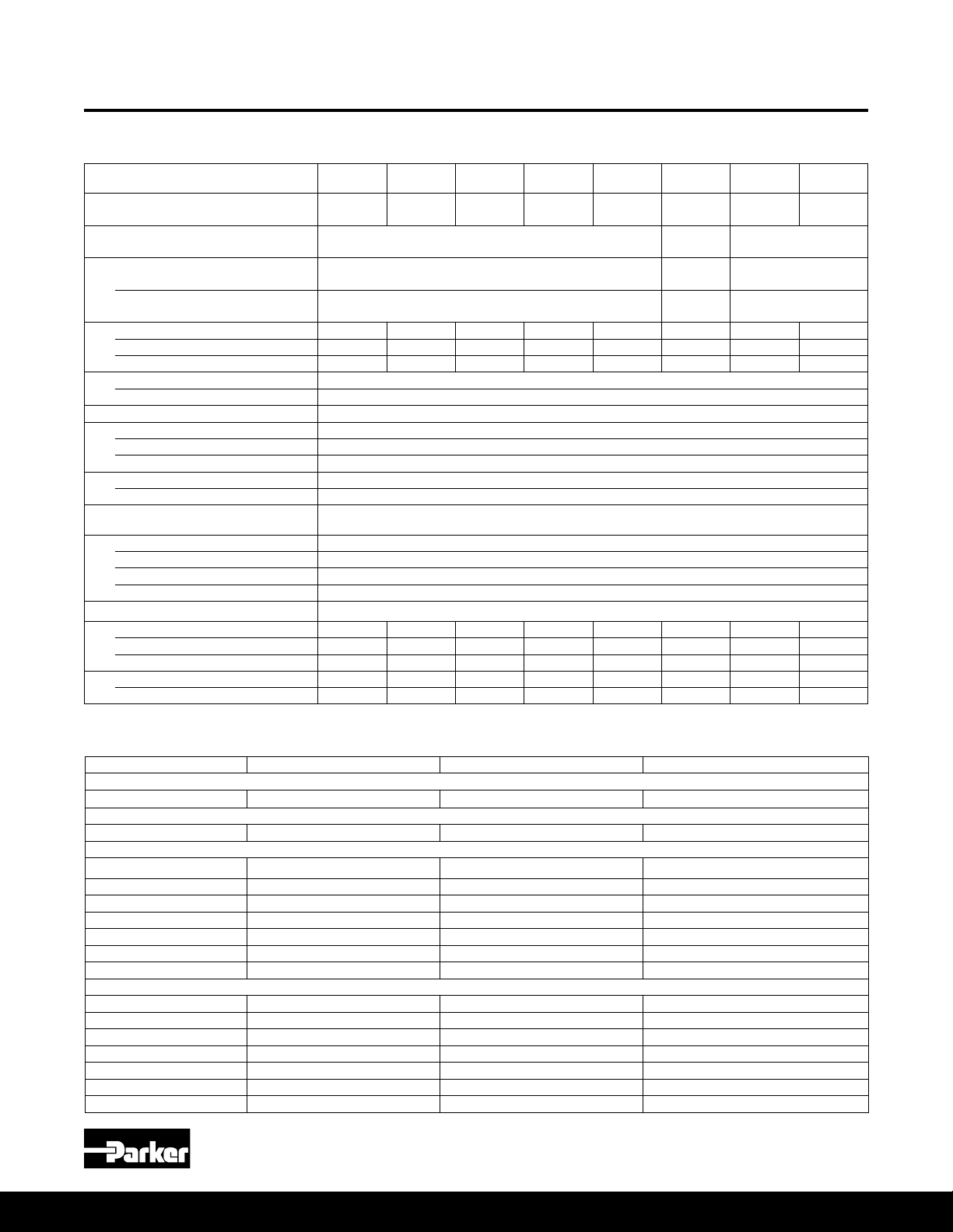
Typical Characteristics
Medium Pressure Axial Piston Pumps
P1/PD B-mod Service Information
Technical Data
/rev
P1/PD
018
3500 3400 3100 2800 2700 2700 2500 2400
°F
2
760 1555 3208 4548 5041 5041 12027 21400
2
793 1618 3268 4687 5207 5207 12402 22343
Model
Maximum Displacement, cm
Outlet Pressure – Continuous
P1 Maximum Speed (1.3 bar abs inlet), rpm
P1 (1.0 bar abs inlet), rpm 3300 3200 2800 2500 2400 2400 2250 2100
P1 (0.8 bar abs inlet), rpm 2900 2900 2400 2200 2100 2100 1900 1800
PD Maximum Speed (1.0 bar abs inlet), rpm
PD (0.8 bar abs inlet), rpm 1800
Minimum Speed, rpm 600
Inlet Pressure – Maximum 11 bar absolute (160 psi)
Case Pressure – Peak, bar 4.0 bar absolute (58 psi) and less than 0.5 bar (7.3 psi) above inlet pressure
Fluid Temperature Range, °C
Fluid Viscosity – Rated, cSt 7 to 160
Optimum Range, cSt 14-50 cSt.
Max. Intermittent, cSt 5000 (for cold starting)
Min. Intermittent, cSt 5
Fluid Contamination – Rated, ISO 20/18/14
Weight – End Port, kg (lb) 13.4 (29.5) 17.7 (39.0) 23 (50) 29 (64) 30 (66) 30 (66) 51 (112) 66 (145)
Side Port, kg (lb) 14.2 (31.3) 18.1 (40.0) 24 (52) 30 (67) 31 (68) 31 (68) 53 (117) 67 (147)
Thru-Drive, kg (lb) 15 (34) 22 (48) 27 (59) 34 (75) 35 (77) 35 (77) 55 (121) 82 (180)
Moment of Inertia kg·mm
Moment of Inertia Thru-Drive kg·mm
*Intermittent pressure is dened as less than 10% of operation time, not exceeding 6 successive seconds.
3
cu.in./rev181.10
Intermittent*
Peak
Rated 1.0 bar absolute (14.5 psi)
Minimum 0.8 bar absolute (11.6 psi)
Rated, bar 2.0 bar absolute (29 psi) and less than 0.5 bar (7.3 psi) above inlet pressure
P1/PD
028
28
1.71
P1/PD
045
45
2.75
280 bar
(4060 psi)
320 bar
(4640 psi)
350 bar
(5075 psi)
P1/PD
060
60
3.66
-40 to +95
-40 to +203
P1/PD
1800
075
75
4.58
P1/PD
085
85
5.19
250 bar
(3600 psi)
300 bar
(4350 psi)
320 bar
(4600 psi)
P1/PD
100
100
6.01
P1/PD
140
140
8.54
280 bar
(4060 psi)
320 bar
(4640 psi)
350 bar
(5075 psi)
Typical Adjustment Ranges and Initial Settings for B-Mod Controls (Unless Customer Specified at Time of Order)
Function Adjustment Range Adjustment Value Recommended or Initial Setting
Pressure compensator settings
C, L, AM Controls 26-280 bar (380-4060 PSI) 55 bar/turn (800 PSI/turn) Default factory setting = 1000 PSI
Load sense differential settings
"L0" and “L2” 10-40 bar (150-580 PSI) 16 bar/turn (230 PSI/turn) 20 bar (290 PSI)
Maximum volume stop
018 100-40% 9% per turn (1.6 cc/turn) 100%
028 100-40% 8.2% per turn (2.3 cc/turn) 100%
045 100-20% 7.5% per turn (3.4 cc/turn) 100%
060 100-30% 6.8% per turn (4.1 cc/turn) 100%
075/085 100-35% 6.2% per turn (4.65 cc/turn) 100%
100 100-50% 5.5% per turn (5.5 cc/turn) 100%
140 100-50% 4.8% per turn (6.72 cc/turn) 100%
Minimum volume stop
018 0-68% 10% per turn (1.8 cc/turn) 0%
028 0-40% 9% per turn (2.6 cc/turn) 0%
045 0-40% 8.2% per turn (3.7 cc/turn) 0%
060 0-50% 4.6% per turn (2.76 cc/turn) 0%
075/085 0-45% 4.3% per turn (3.23 cc/turn) 0%
100 0-45% 3.9% per turn (3.9 cc/turn) 0%
140 0-25% 3.3% per turn (4.62 cc/turn) 0%
Parker Hannin Corporation
Hydraulic Pump and Power Systems Division
6
Marysville, Ohio USA
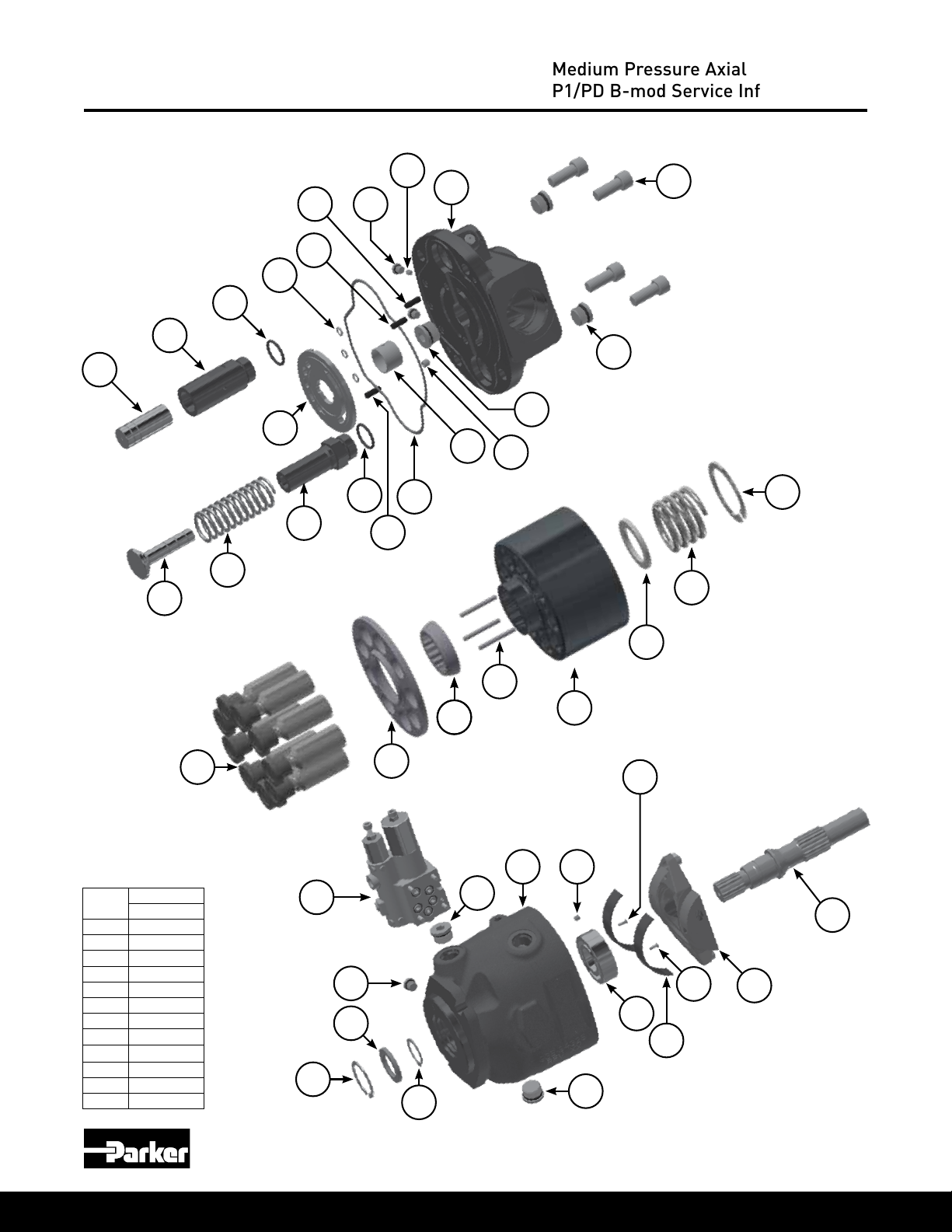
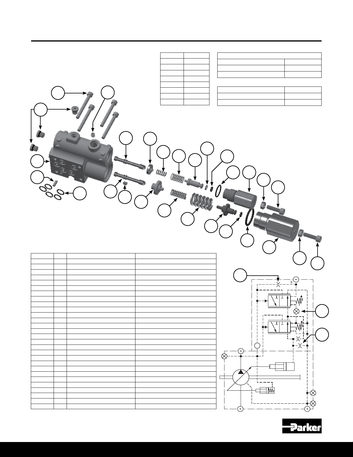
Page 7

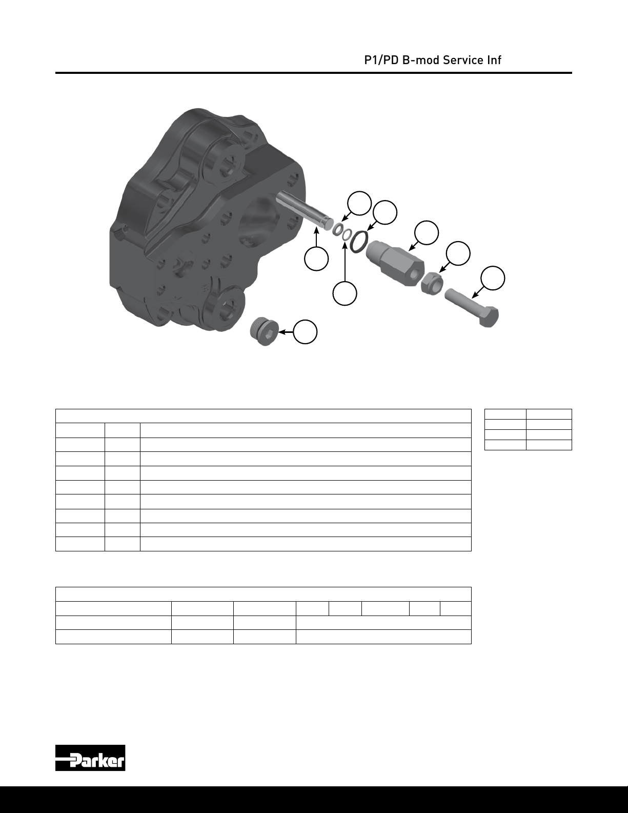
Bulletin HY28-2708-02/SVC/EN | July 2019
018, 028 B-mod Pump Exploded View
* Clockwise Rotation Shown
5
7
16
8
14
15
Medium Pressure Axial Piston Pumps
P1/PD B-mod Service Information
36
1
2
12
13
11
4
27
20
17
18
19
22
23
9
21
24
25
2930
26
34
36
35
Item
2 52 ft-lbs 52 ft-lbs
3 45 ft-lbs 45 ft-lbs
5 6 ft-lbs 6 ft-lbs
6 25 in-lbs 25 in-lbs
16 12 in-lbs 70 in-lbs
19 45 ft-lbs 45 ft-lbs
30 30 in-lbs 30 in-lbs
34 70 in-lbs 70 in-lbs
36 16 ft-lbs 45 ft-lbs
37 14 ft-lbs 14 ft-lbs
38 70 in-lbs 70 in-lbs
Parker Hannin Corporation
Hydraulic Pump and Power Systems Division
Marysville, Ohio USA
18 28
Torque Torque
28
38
41
37
39
40
7
30
31
32
42
43
46
36
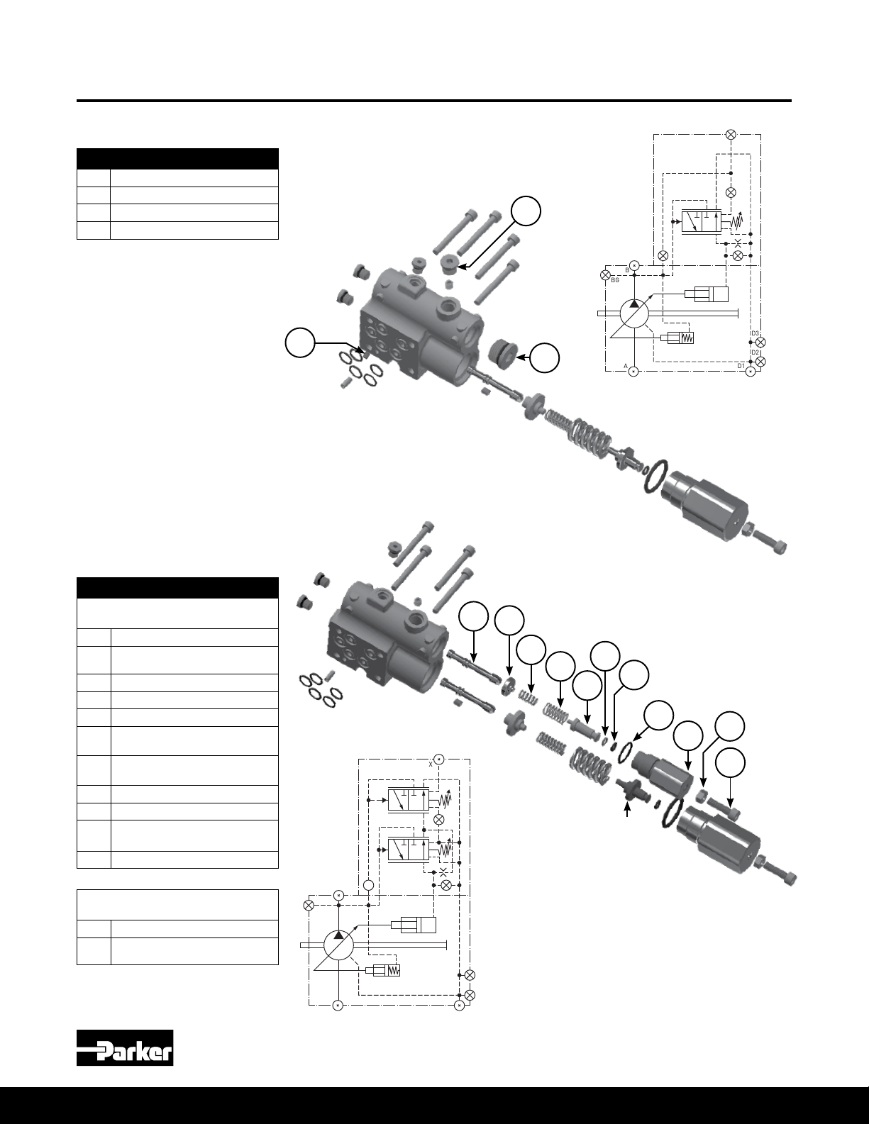
Page 8
Bulletin HY28-2708-02/SVC/EN | July 2019
045 B-mod Pump Exploded View
* Clockwise Rotation Shown
7
17
8
10
14
15
9
Medium Pressure Axial Piston Pumps
P1/PD B-mod Service Information
6
3
1
5
2
19
18
16
12
Item
1 63 ft-lbs
2 45 ft-lbs
5 6 ft-lbs
6 25 in-lbs
11 105 ft-lbs
14 105 ft-lbs
16 10 ft-lbs
19 46 ft-lbs
30 30 in-lbs
34 70 in-lbs
36 75 ft-lbs
37 14 ft-lbs
45
Torque
27
13
11
41
40
37
39
10
17
26
4
42
25
36
24
35
23
34
36
30
32
22
31
21
30
20
28
29
Parker Hannin Corporation
Hydraulic Pump and Power Systems Division
8
Marysville, Ohio USA
Page 9
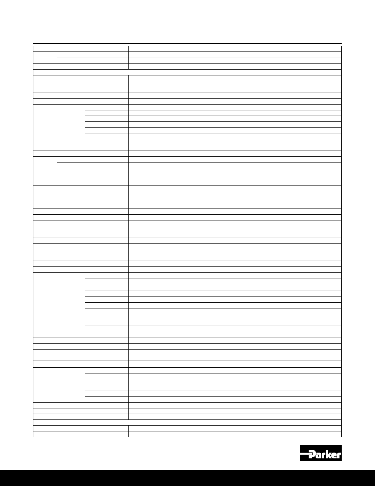
Bulletin HY28-2708-02/SVC/EN | July 2019
018, 028, 045 Pump Parts
Medium Pressure Axial Piston Pumps
P1/PD B-mod Service Information
Item No Qty 018 Part No 028 Part No 045 Part No Description
1
2* 2 108X8V 108X8V 108X8V Volume stop boss plug & O-ring
3 1 Contact factory for port block ordering information. Port block
4* 1 2050V-7 2160V-7 675-00162-0 Port block O-ring
5* 4 108X2V 108X2V 108X2V Boss plug & O-ring
6 1 226X42 226X42 226X42 M5X6 Control Flow Set Screw
7 1 299X67 324-30014-0 324-30014-0 Port plate pin
8* 3 605-10077-0 605-10077-0 605-10077-0 Control pressure passage o-rings
9*** 1
10* 2 ** ** 695-00912-0 Bias and control rod O-ring
11
12 1 03E-94428-0 03E-94391-0 03E-94354-0 Bias piston
13
14
15 1 03E-94426-0 03E-94389-0 03E-94352-0 Control piston
16 1 226X14 226X56 102x1 Ripple chamber plug (side ported version only)
17 2 299X123 299X123 299X123 Cover dowel pin
18 1 216-10013-0 789814 230-82227-0 Port block bushing
19 1 102X8V 102X8V 108X10V Ripple chamber plug
20 1 256X521 256X525 356-65144-0 Retaining ring, internal
21 1 787635 03E-94387-0 03E-94350-0 Barrel hold down spring
22 2 (1:045) 786996 03E-94388-0 03E-94351-0 Barrel hold down washer
23 1 03E-94717-0 03E-94375-0 03E-94338-0 Barrel
24 3 787000 03E-94386-0 03E-95903-0 Barrel hold down pin
25 1 787002 03E-94385-0 03E-96852-0 Spherical washer
26 1 786994 03E-97011-0 03E-96988-0 Retainer plate
27 9 789641 S2E-18415-0 S2E-18413-0 Piston and shoe assembly
28 1
29 1 S2E-19079-0 S2E-18414-0 S2E-18412-0 Cam
30 2 03E-94359-0 03E-94359-0 03E-94359-0 Bearing retainer screws
31 2 03E-94432-0 03E-94395-0 03E-94358-0 Cam bearing
32 1 230-82515-0 789815 230-82516-0 Cylindrical roller bearing
34 1 226X56 226X56 226X56 M6X6 bias ow set screw
35 1 ** ** ** Housing (not sold separately)
36* 2
37* 1
38* 1 P2-000-3506-08 P2-000-3506-08 ** M6X6 set screw with 0.8mm orice
39* 1 787140 P2-060-3304 620-82125-5 Shaft seal
40 1 256X535 256X544 356-65158-0 Seal retainer
41 1 See separate compensator ordering information Compensator
42 1 256X222 256X222 356-65159-0 External retaining ring (shaft)
43 1 256X544 256X544 ** Internal retaining ring (housing)
* Denotes seal or O-ring is included in the seal kit
Parker Hannin Corporation
Hydraulic Pump and Power Systems Division
Marysville, Ohio USA
4 210x209 210x211 361-12229-0 Socket head cap screws
4 ** 210x209 ** Socket head cap screws (28cc thru drive version only)
03E-94415-0 03E-94969-0 03E-94339-0 Port plate, CW, industrial (PD)
03E-94414-0 03E-94970-0 03E-94340-0 Port plate, CCW, industrial (PD)
03E-94413-0 03E-94969-0 03E-94341-0 Port plate, CW, mobile (P1)
03E-94416-0 03E-94970-0 03E-94342-0 Port plate, CCW, mobile (P1)
03E-94963-0 03E-94376-0 03E-95374-0 Port plate, CW, industrial (PD), ripple chamber
03E-94964-0 03E-94377-0 03E-95080-0 Port plate, CCW, industrial (PD), ripple chamber
03E-94965-0 03E-94378-0 03E-95374-0 Port plate, CW, mobile (P1), ripple chamber
03E-94966-0 03E-94379-0 03E-95375-0 Port plate, CCW, mobile (P1), ripple chamber
1 03E-94427-0 03E-94390-0 03E-94355-0 Bias guide
1 ** ** 03E-95658-0 Bias guide (overcenter option)
1 03E-94430-0 03E-94393-0 03E-94356-0 Bias spring
1 ** ** 03E-95656-0 Bias spring (overcenter option)
1 03E-94427-0 03E-94390-0 03E-94353-0 Control guide
1 ** ** 03E-95657-0 Control guide (overcenter option)
03E-94409-0 03E-97070-0 03E-97070-0 01 shaft option, no thru drive
03E-94411-0 03E-94374-0 03E-94337-0 01 shaft option with thru drive
S2E-19657-0 S2E-19661-0 S2E-19665-0 02 shaft option assembly with key (no thru drive)
S2E-19658-0 S2E-19662-0 S2E-19666-0 02 shaft option assembly (thru drive)
S2E-19659-0 S2E-19663-0 S2E-19667-0 04 shaft option assembly with key (no thru drive)
S2E-19660-0 S2E-19664-0 S2E-19668-0 04 shaft option assembly (thru drive)
03E-94718-0 ** ** 06 shaft option assembly (no thru drive)
03E-96233-0 ** ** 06 shaft option assembly (thru drive)
03E-94804-0 03E-95166-0 03E-94990-0 08 shaft option, (no thru drive)
03E-94762-0 03E-95492-0 03E-95197-0 08 shaft option (thru drive)
108X6V 108X8V 108X10V Case drain plug & O-ring - SAE ORB
788153V 788161V 788161V Case drain plug & O-ring - BSPP
788516-06V 788516-10V 788516-10V Case drain plug & O-ring - ISO
108X4V 108X4V 108X4V BG port plug & O-ring - SAE ORB
789189V 789189V 789189V BG port plug & O-ring - BSPP
788516-04V 788516-04V 788516-04V BG port plug & O-ring - ISO
| *** Contact factory for 045 overcenter "X" port plate part number information
9
Page 10
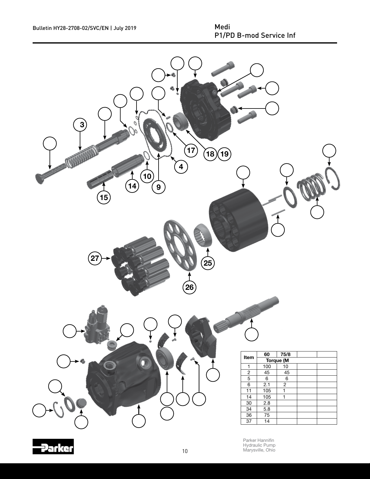
Bulletin HY28-2708-02/SVC/EN | July 2019
060, 075, 085, 100, 140 B-mod Pump Exploded View
* Counter-clockwise Rotation Shown
36
5
Medium Pressure Axial Piston Pumps
P1/PD B-mod Service Information
16
12
13
27
11
15
10
14
8
7
1
2
10
17
4
18 19
23
22
20
9
21
24
25
40
39
37
41
36
36
35
34
32
33
30
31 30
10
26
29
28
Item
Parker Hannin Corporation
Hydraulic Pump and Power Systems Division
Marysville, Ohio USA
60 75/85 100 140
Torque (Measured in ft-lbs)
1 100 100 170 205
2 45 45 45 45
5 6 6 6 6
6 2.1 2.1 2.1 2.1
11 105 105 136 170
14 105 105 136 170
30 2.8 2.8 2.8 2.8
34 5.8 5.8 5.8 5.8
36 75 85 85 135
37 14 14 14 14
Page 11
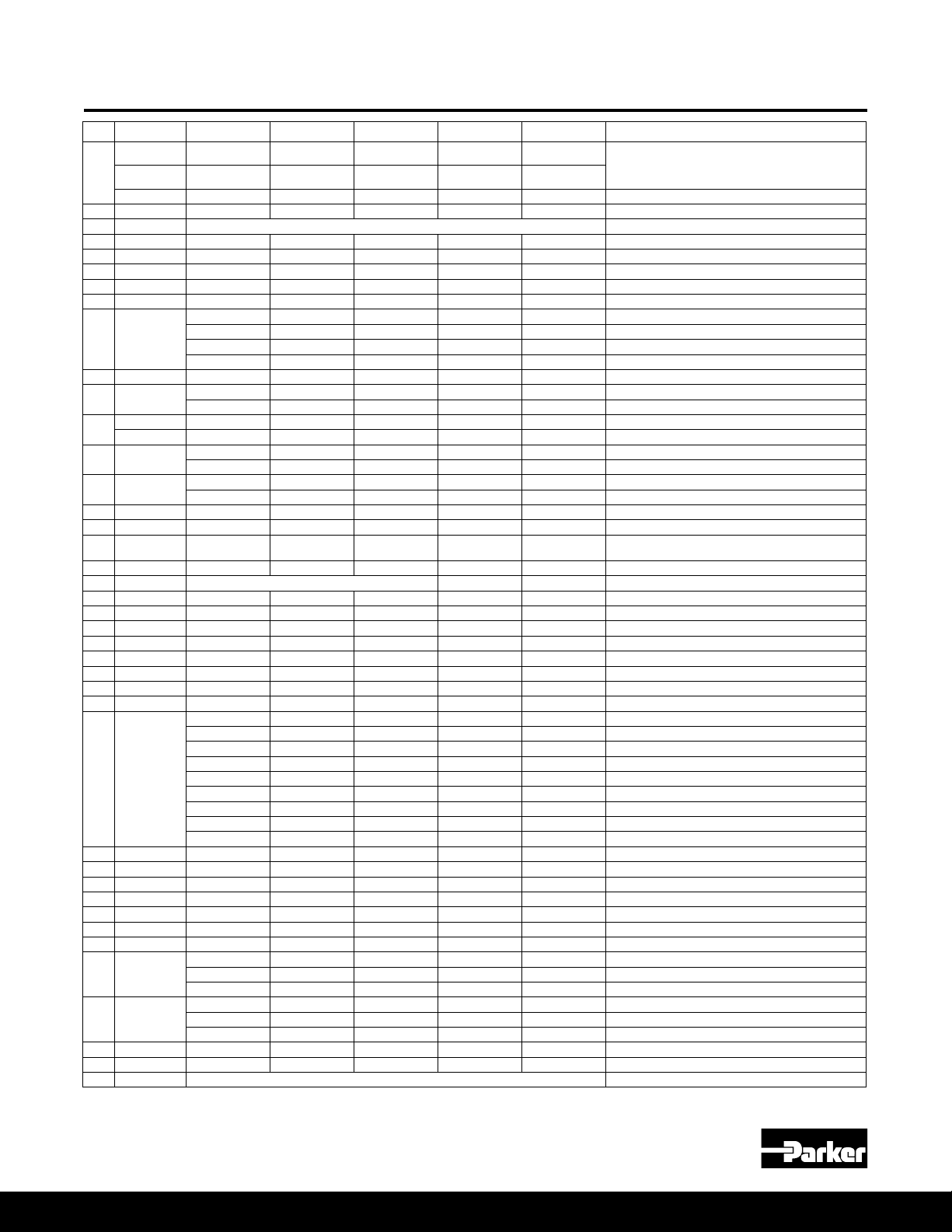
Bulletin HY28-2708-02/SVC/EN | July 2019
060, 075, 085, 100, 140 Pump Parts
Medium Pressure Axial Piston Pumps
P1/PD B-mod Service Information
Item
No
2* 2 108X8V 108X8V 108X8V 108X8V 108X8V Volume stop boss plug & O-ring
4* 1 675-00164-0 675-00165-0 675-00165-0 675-00169-0 675-00173-0 Port block O-ring
5* 2 108X2V 108X2V 108X2V 108X2V 108X2V Boss plug & O-ring
8* 3 605-10070-0 605-10070-0 605-10070-0 605-10070-0 605-10070-0 Control pressure O-rings
9*** 1
10* 2 695-00912-0 695-00912-0 695-00912-0 695-00914-0 695-00916-0 Bias and control rod O-ring
11 1
12
13 1
14 1
15 1 03E-94051-0 03E-93147-0 03E-93147-0 03E-93797-0 03E-94751-0 Control piston
16* 2 108X4V 108X4V 108X4V 108X4V 108X4V Boss plug & O-ring
17 1 S2E-18591-0K S2E-18591-0K S2E-18591-0K S2E-18640-0K S2E-18527-0K
18 1 230-82237-0 230-82237-0 230-82237-0 230-82244-0 230-82239-0 Tapered roller bearing cup
19 1 INCLUDED IN ITEM 18 230-82518-0
20 1 356-65152-0 356-65144-0 356-65144-0 356-65146-0 356-65147-0 Retaining ring, internal
21 1 03E-94049-0 03E-93145-0 03E-93145-0 03E-93795-0 03E-93959-0 Barrel hold down spring
22 1 03E-94050-0 03E-93146-0 03E-93146-0 03E-93796-0 03E-93244-0 Barrel hold down washer
23 1 03E-94036-0 03E-93129-0 03E-95465-0 03E-95603-0 03E-93242-0 Barrel
24 3 03E-95904-0 03E-95905-0 03E-95905-0 03E-95906-0 03E-95907-0 Barrel hold down pin
25 1 03E-94047-0 03E-93142-0 03E-93142-0 03E-93794-0 03E-93241-0 Spherical washer
26 1 03E-97012-0 03E-93139-0 03E-95501-0 03E-93793-0 03E-93240-0 Retainer plate
27 9 S2E-18296-0 S2E-17003-0 S2E-19330-0 S2E-17912-0 S2E-17323-0 Piston and shoe assembly
28 1
29 1 S2E-18411-0 S2E-17443-0 S2E-17443-0 S2E-17961-0 S2E-17957-0 Cam
30 2 03E-93763-0 03E-93763-0 03E-93763-0 03E-93763-0 03E-93763-0 Bearing retainer screws
31 2 03E-94057-0 03E-93950-0 03E-93950-0 03E-93952-0 03E-93953-0 Cam bearing
32 1 230-82236-0 230-82236-0 230-82236-0 230-82519-0 230-82241-0 Tapered roller bearing cone (and cup 140)
33 1 230-82235-0 230-82235-0 230-82235-0 230-82245-0 ** Tapered roller bearing cup
34 1 226X56 226X56 226X56 226X56 226X56 M6X6 bias ow set screw
35 1 ** ** ** ** ** Housing (not sold separately)
36* 2
37* 1
39* 1 620-82118-5 620-82118-5 620-82118-5 620-82121-5 620-82120-5 Shaft seal
40 1 356-65146-0 356-65146-0 356-65146-0 356-65147-0 356-65148-0 Seal retainer
41 1 See separate compensator ordering information. Compensator
Qty 060 Part No 075 Part No 085 Part No 100 Part No 140 Part No Description
4
(2: 075/085)
0
1
(2: 075/085)
4 361-13250-0 361-13250-0 361-13250-0 361-14290-0 361-15267-0 Socket head cap screws (thru drive version only)
3 1 Contact factory for port block ordering information. Port block
6 1 226X42 226X42 226X42 226X42 226X42 M5X6 control ow set screw
7 1 324-30014-0 324-30014-0 324-30014-0 324-30014-0 324-30014-0 Port plate pin
1 03E-94053-0 03E-93149-0 03E-93149-0 03E-93799-0 03E-94658-0 Bias piston
1 03E-94835-0 03E-93149-0 ** 03E-93799-0 03E-94658-0 Bias piston (overcenter option "X")
361-13250-0 361-13270-0 361-13270-0 361-14290-0 361-15270-0
361-13250-0 361-13250-0 361-13250-0 361-14290-0 361-15270-0
03E-94038-0 03E-93169-0 03E-93169-0 03E-95605-0 03E-93252-0 Port plate, CW, industrial (PD)
03E-94039-0 03E-93170-0 03E-93170-0 03E-95606-0 03E-93253-0 Port plate, CCW, industrial (PD)
03E-94040-0 03E-93171-0 03E-93171-0 03E-95607-0 03E-93254-0 Port plate, CW, mobile (P1)
03E-94041-0 03E-93172-0 03E-93172-0 03E-95608-0 03E-93255-0 Port plate, CCW, mobile (P1)
03E-94054-0 03E-93150-0 03E-93150-0 03E-93800-0 03E-93248-0 Bias guide
03E-94832-0 03E-94498-0 ** 03E-94827-0 03E-94743-0 Bias guide (overcenter option “X”)
03E-94055-0 03E-93151-0 03E-93151-0 03E-93801-0 03E-93963-0 Bias spring
03E-94834-0 03E-94499-0 ** 03E-94829-0 03E-94752-0 Bias spring (overcenter option “X”)
03E-94052-0 03E-93148-0 03E-95471-0 03E-93798-0 03E-97335-0 Control guide
03E-94833-0 03E-94608-0 ** 03E-94828-0 03E-93246-0 Control guide (overcenter option “X”)
INCLUDED IN ITEM 18
03E-94032-0 03E-97070-0 03E-97070-0 03E-93779-0 03E-93227-0 01 shaft, no thru drive
03E-94033-0 03E-94000-0 03E-94000-0 03E-93780-0 03E-93228-0 01 shaft with thru drive
S2E-19669-0 S2E-19673-0 S2E-19673-0 S2E-19677-0 S2E-19681-0 02 shaft assembly with key (no thru drive)
S2E-19670-0 S2E-19674-0 S2E-19674-0 S2E-19678-0 S2E-19682-0 02 shaft assembly (thru drive)
S2E-19671-0 S2E-19675-0 S2E-19675-0 S2E-19679-0 S2E-19683-0 04 shaft assembly with key (no thru drive)
S2E-19672-0 S2E-19676-0 S2E-19676-0 S2E-19680-0 S2E-19684-0 04 shaft assembly (thru drive)
03E-95611-0 ** ** 03E94500-0 ** 06 (100cc) & 09 (60cc) shaft, no thru drive
03E-96177-0 ** ** 03E-94462-0 ** 06 (100cc) & 09 (60cc) shaft, thru drive
03E-96216-0 ** ** ** ** 10 shaft, no thru drive
108X10V 108X12V 108X12V
788175V 788175V 788175V 788175V 447-00038-5 Case drain plug & O-ring - BSPP
788516-10V 788516-12V 788516-12V 788516-12V 788516-16V Case drain plug & O-ring - ISO
108X4V 108X4V 108X4V 108X4V 108X4V BG port plug & O-ring - SAE ORB
789189V 789189V 789189V 789189V 789189V BG port plug & O-ring - BSPP
788516-04V 788516-04V 788516-04V 788516-04V 788516-04V BG port plug & O-ring - ISO
108X12V 108X16V Case drain plug & O-ring - SAE ORB
Socket head cap screws (non-thru drive version)
Bearing shim kit (includes all standard shim
sizes)
Tapered roller bearing cone
* Denotes seal or O-ring is included in the seal kit | *** Contact factory for overcenter "X" port plate part number information
Parker Hannin Corporation
Hydraulic Pump and Power Systems Division
Marysville, Ohio USA
11
Page 12
Bulletin HY28-2708-02/SVC/EN | July 2019
Volume Stop Control
Medium Pressure Axial Piston Pumps
P1/PD B-mod Service Information
59
57
56
60
58
2
NOTE: Picture shows max volume stop location for counter-clockwise rotation and min volume stop
location for clockwise rotation. Plug and stop assembly locations would be switched for opposite rotation.
Volume Stop Parts
Item No Qty Description
2 1 Plug with O-ring (no volume stop)
54 1 Adjusting screw
55 1 Adjusting screw lock nut
56 1 Volume stop plug
57 1 Volume stop plug O-ring
58 1 Backup ring
59 1 Volume stop rod O-ring
60* 1 Volume stop rod
*Min & max rods same for the 45 thru 140, but different on the 18 & 28. See table below for kit part number.
55
54
Item Torque
2 45 ft-lbs
55 18 ft-lbs
56 45 ft-lbs
Volume Stop Kits
Size 018 028 045 060 075/085 100 140
Maximum volume stop kit S2E-19203-5K S2E-19204-5K S2E-19115-5K
Minimum volume stop kit S2E-19608-5K S2E-19609-5K S2E-19115-5K
Parker Hannin Corporation
Hydraulic Pump and Power Systems Division
12
Marysville, Ohio USA
Page 13
Bulletin HY28-2708-02/SVC/EN | July 2019
Thru Drive Couplings and O-rings
Medium Pressure Axial Piston Pumps
P1/PD B-mod Service Information
Thru Drive
Pad Coupling
Thru Drive
Pad Coupling
SAE A, 9 Tooth S2E-19538-0 S2E-19364-0 03E-94942-0 03E-93278-0 03E-93278-0 03E-94274-0 03E-93947-0 695-00237-0
SAE A, 11 Tooth S2E-19726-0 S2E-19391-0 03E-94943-0 03E-94724-0 03E-94724-0 03E-94657-0 03E-95706-0 695-00237-0
SAE B, 13 Tooth ** S2E-19365-0 03E-94945-0 03E-93277-0 03E-93277-0 03E-94273-0 03E-93946-0 695-00243-0
SAE BB, 15 Tooth ** S2E-19409-0 03E-94361-0 03E-93279-0 03E-93279-0 03E-94272-0 03E-93945-0 695-00243-0
SAE C, 14 Tooth ** ** ** 03E-93276-0 03E-93276-0 03E-94271-0 03E-93944-0 695-00251-0
SAE CC, 17 Tooth ** ** ** ** ** 03E-94270-0 03E-93943-0 695-00251-0
SAE D&E, 13 Tooth ** ** ** ** ** ** 03E-93942-0 695-00259-0
018 028 045 060 075/085 100 140
Thru Drive Couplings
O-ring
Parker Hannin Corporation
Hydraulic Pump and Power Systems Division
Marysville, Ohio USA
13
Page 14
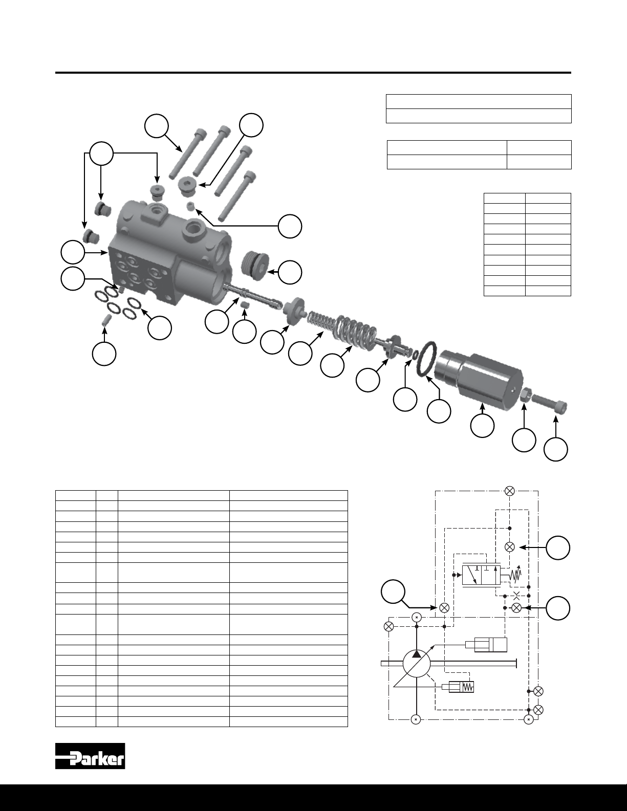
Bulletin HY28-2708-02/SVC/EN | July 2019
C0 B-mod Control Exploded View
12
Medium Pressure Axial Piston Pumps
P1/PD B-mod Service Information
C0 Controller Assembly Part Number
S2E-20171-5T
18
31
17
13
15
14
Pmax Spool Kit* S2E-20821-5K
Seal Kit (C, L, & AM controls) S2E-20363-5K
* Includes items 1-11, 16 & 17
Item Torque
2 30 in-lbs
16
19
9 85 ft-lbs
10 70 in-lbs
12 45 in-lbs
13 35 in-lbs
16 40 in-lbs
17 12 in-lbs
18 11 ft-lbs
19 50 ft-lbs
1
2
3
4
5
6
7
8
9
10
11
Item Qty Part Number Description
1 1 03E-95926-0 Pmax spool
2 1 226X42 M5 x 6 set screw
3 1 Available in kit only Pmax inner spring guide
4 1 Available in kit only Pmax inner spring
5 1 Available in kit only Pmax outer spring
6 1 Available in kit only Pmax outer spring guide
7* 1 Available in kit only
8* 1 Available in kit only Pmax main O-ring
9 1 03E-95570-0 Pmax outer cap
10 1 340-00063-0 Pmax adjustment lock nut
11 1 361-08275-0
12 4 361-07253-8 M5 x 45 SHCS
13* 3 108X2V SAE Boss Plug & O-ring
14* 5 Available in kit only Compensator teon O-ring
15 1 325-36001-0 Compensator M4 x 10 roll pin
16 1 226X56 M6 x 6 set screw
17 1 226X26 M4 x 5 set screw
18 1 108X4V Boss plug & O-ring - SAE
19 1 108X8V Boss plug & O-ring
31 1 Not sold separately Compensator housing
*Included in C, L, & AM controls seal kit
Pmax outer spring guide
O-ring
Pmax M6x22 adjustment
screw
14
X
16
17
2
B
BG
D3
D2
D1A
Parker Hannin Corporation
Hydraulic Pump and Power Systems Division
Marysville, Ohio USA
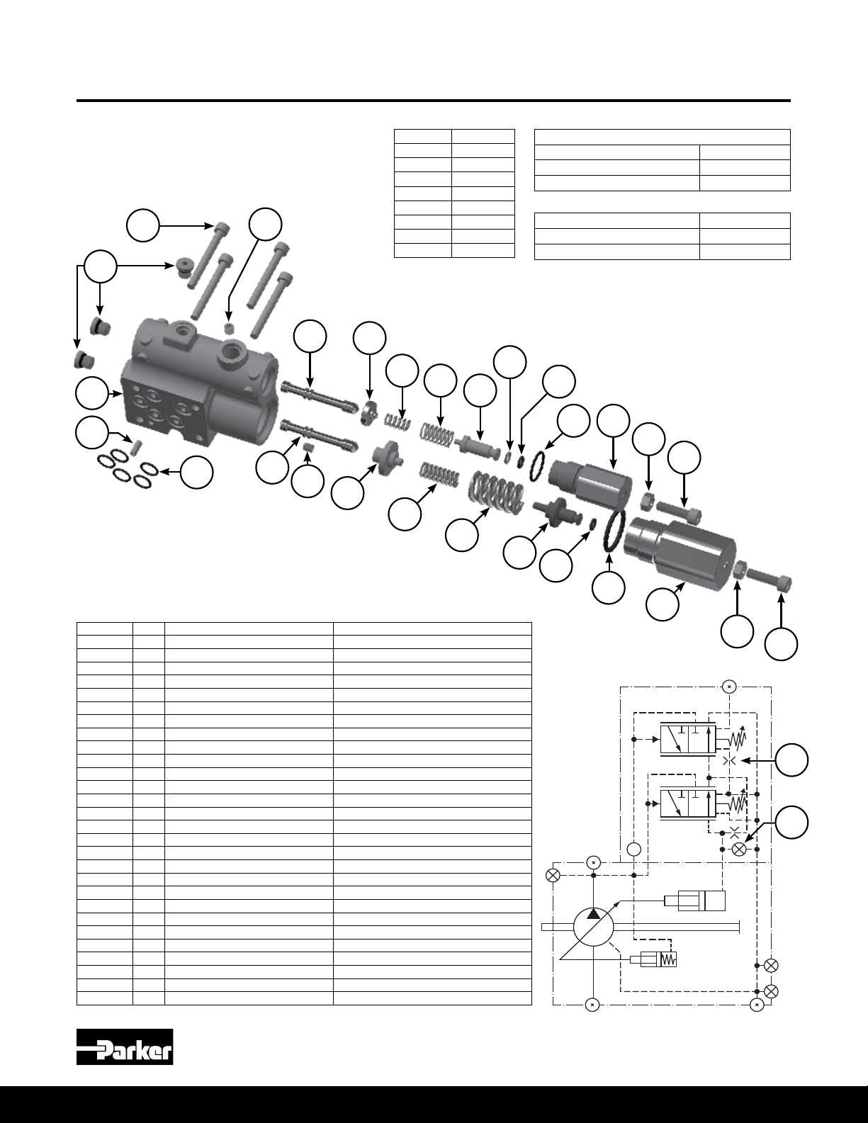
Page 15

Bulletin HY28-2708-02/SVC/EN | July 2019
X
B
BG
D3
D2
D1A
L0 B-mod Control Exploded View
Medium Pressure Axial Piston Pumps
P1/PD B-mod Service Information
13
31
15
12
14
16
Item Torque
2 30 in-lbs
9 85 ft-lbs
10 70 in-lbs
12 45 in-lbs
13 35 in-lbs
16 40 in-lbs
28 50 ft-lbs
29 70 in-lbs
20
21
22
23
25
24
1
2
L0 Controller Assembly Part Numbers
SAE* S2E-19440-5T
Metric* S2E-20186-5T
BSPP* S2E-20189-5T
* Designates load sense port thread type
Pmax Spool Kit** S2E-20821-5K
Load Sense Spool Kit*** S2E-20822-5K
Seal Kit (C, L, & AM controls) S2E-20363-5K
** Includes items 1-11, 16 & 17
*** Includes items 2, 16, 20-30
26
28
27
29
30
3
4
5
6
7
8
9
Item Qty Part Number Description
1 1 03E-95926-0 Pmax spool
2 1 226X42 M5 x 6 set screw
3 1 Available in kit only Pmax inner spring guide
4 1 Available in kit only Pmax inner spring
5 1 Available in kit only Pmax outer spring
6 1 Available in kit only Pmax outer spring guide
7* 1 Available in kit only Pmax outer spring guide O-ring
8* 1 Available in kit only Pmax main O-ring
9 1 03E-95570-0 Pmax outer cap
10 1 340-00063-0 Pmax adjustment lock nut
11 1 361-08275-0 Pmax M6x22 adjustment screw
12 4 361-07253-8 M5 x 45 SHCS
13* 3 108X2V SAE Boss Plug & O-ring
14* 5 Available in kit only Compensator teon O-ring
15 1 325-36001-0 Compensator M4 x 10 roll pin
16 1 226X56 M6 x 6 set screw
20 1 03E-95926-0 Differential spool
21 1 Available in kit only Differential inner spring guide
22 1 Available in kit only Differential inner spring
23 1 Available in kit only Differential outer spring
24 1 Available in kit only Differential outer spring guide
25* 1 Available in kit only Differential inner spring guide O-ring
26* 1 Available in kit only Differential inner spring guide O-ring
27* 1 Available in kit only Differential main O-ring
28 1 03E-95572-0 Differential outer cap
29 1 340-00063-0 Differential adjustment lock nut
30 1 361-08275-0 Differential M6x22 adjustment screw
31 1 Not sold separately Compensator housing
*Included in C, L, & AM controls seal kit
Parker Hannin Corporation
Hydraulic Pump and Power Systems Division
Marysville, Ohio USA
15
10
11
16
2
Page 16
Bulletin HY28-2708-02/SVC/EN | July 2019
X
B
BG
D3
D2
D1A
L2 B-mod Control Exploded View
Medium Pressure Axial Piston Pumps
P1/PD B-mod Service Information
13
31
15
12
14
16
Item Torque
2 30 in-lbs
9 85 ft-lbs
10 70 in-lbs
12 45 in-lbs
13 35 in-lbs
16 40 in-lbs
28 50 ft-lbs
29 70 in-lbs
20
21
22
23
25
24
1
2
L2 Controller Assembly Part Numbers
SAE* S2E-20196-5T
Metric* S2E-20187-5T
BSPP* S2E-20190-5T
* Designates load sense port thread type
Pmax Spool Kit** S2E-20821-5K
Load Sense Spool Kit*** S2E-20822-5K
Seal Kit (C, L, & AM controls) S2E-20363-5K
** Includes items 1-11, 16 & 17
*** Includes items 2, 16, 20-30
26
28
27
29
30
3
4
5
6
7
8
9
Item Qty Part Number Description
1 1 03E-95926-0 Pmax spool
2 1 226X42 M5 x 6 set screw
3 1 Available in kit only Pmax inner spring guide
4 1 Available in kit only Pmax inner spring
5 1 Available in kit only Pmax outer spring
6 1 Available in kit only Pmax outer spring guide
7* 1 Available in kit only Pmax outer spring guide O-ring
8* 1 Available in kit only Pmax main O-ring
9 1 03E-95570-0 Pmax outer cap
10 1 340-00063-0 Pmax adjustment lock nut
11 1 361-08275-0 Pmax M6x22 adjustment screw
12 4 361-07253-8 M5 x 45 SHCS
13* 3 108X2V SAE Boss Plug & O-ring
14* 5 Available in kit only Compensator teon O-ring
15 1 325-36001-0 Compensator M4 x 10 roll pin
16 1 P2-000-3506-04 M6 x 6 set screw with 0.4mm orice
20 1 03E-95926-0 Differential spool
21 1 Available in kit only Differential inner spring guide
22 1 Available in kit only Differential inner spring
23 1 Available in kit only Differential outer spring
24 1 Available in kit only Differential outer spring guide
25* 1 Available in kit only Differential inner spring guide O-ring
26* 1 Available in kit only Differential inner spring guide O-ring
27* 1 Available in kit only Differential main O-ring
28 1 03E-95572-0 Differential outer cap
29 1 340-00063-0 Differential adjustment lock nut
30 1 361-08275-0 Differential M6x22 adjustment screw
31 1 Not sold separately Compensator housing
*Included in C, L, & AM controls seal kit
Parker Hannin Corporation
Hydraulic Pump and Power Systems Division
16
Marysville, Ohio USA
10
11
16
2
Page 17
Bulletin HY28-2708-02/SVC/EN | July 2019
X
B
BG
D3
D2
D1A
AM B-mod Control Exploded View
Medium Pressure Axial Piston Pumps
P1/PD B-mod Service Information
13
31
15
12
14
16
Item Torque
2 30 in-lbs
9 85 ft-lbs
10 70 in-lbs
12 45 in-lbs
13 35 in-lbs
16 40 in-lbs
28 50 ft-lbs
29 70 in-lbs
20
21
22
23
25
24
1
2
AM Controller Assembly Part Numbers
SAE* S2E-20172-5T
Metric* S2E-20188-5T
BSPP* S2E-20191-5T
* Designates remote port thread type
Pmax Spool Kit** S2E-20821-5K
AM Spool Kit*** S2E-20823-5K
Seal Kit (C, L, & AM controls) S2E-20363-5K
** Includes items 1-11, 16 & 17
*** Includes items 2, 16, 20-30
26
28
27
29
30
3
4
5
6
7
8
9
Item Qty Part Number Description
1 1 03E-95926-0 Pmax spool
2 1 03E-93269-0 M5 x 6 set screw with 0.8mm orice
3 1 Available in kit only Pmax inner spring guide
4 1 Available in kit only Pmax inner spring
5 1 Available in kit only Pmax outer spring
6 1 Available in kit only Pmax outer spring guide
7* 1 Available in kit only Pmax outer spring guide O-ring
8* 1 Available in kit only Pmax main O-ring
9 1 03E-95570-0 Pmax outer cap
10 1 340-00063-0 Pmax adjustment lock nut
11 1 361-08275-0 Pmax M6x22 adjustment screw
12 4 361-07253-8 M5 x 45 SHCS
13* 3 108X2V SAE Boss Plug & O-ring
14* 5 Available in kit only Compensator teon O-ring
15 1 325-36001-0 Compensator M4 x 10 roll pin
16 1 226X56 M6 x 6 set screw
20 1 03E-95860-0 Differential spool
21 1 Available in kit only Differential inner spring guide
22 1 Available in kit only Differential inner spring
23 1 Available in kit only Differential outer spring
24 1 Available in kit only Differential outer spring guide
25* 1 Available in kit only Differential inner spring guide O-ring
26* 1 Available in kit only Differential inner spring guide O-ring
27* 1 Available in kit only Differential main O-ring
28 1 03E-95572-0 Differential outer cap
29 1 340-00063-0 Differential adjustment lock nut
30 1 361-08275-0 Differential M6x22 adjustment screw
31 1 Not sold separately Compensator housing
*Included in C, L, & AM controls seal kit
Parker Hannin Corporation
Hydraulic Pump and Power Systems Division
Marysville, Ohio USA
17
20
10
11
16
2
Page 18
Bulletin HY28-2708-02/SVC/EN | July 2019
C0 to L0 B-mod Conversion Guide
Medium Pressure Axial Piston Pumps
P1/PD B-mod Service Information
C0
Remove
Item Description
17 M4 x 5 set screw
18 Boss plug & O-ring - SAE
19 Boss plug & O-ring
17
18
19
X
B
BG
D3
D2
D1A
L0
Add
Kit #1
S2E-20463-5K
Item Description
21 Differential inner spring guide
22 Differential inner spring
23 Differential outer spring
24 Differential outer spring guide
Differential inner spring guide
25
O-ring
Differential inner spring guide
26
O-ring
27 Differential main O-ring
28 Differential outer plug
29 Differential adjustment lock nut
30 Differential adjustment screw
Kit #4
S2E-20466-5K
Item Description
20 Load sense differential spool
20
21
22
23
X
B
BG
D3
D2
D1A
24
25
26
27
28
29
30
18
Parker Hannin Corporation
Hydraulic Pump and Power Systems Division
Marysville, Ohio USA
Page 19

Bulletin HY28-2708-02/SVC/EN | July 2019
C0 to L2 B-mod Conversion Guide
Medium Pressure Axial Piston Pumps
P1/PD B-mod Service Information
C0
Remove
Item Description
16 M6 x 6 set screw
17 M4 x 5 set screw
18 Boss plug & O-ring SAE
19 Boss plug & O-ring
17
16
18
19
16
X
B
BG
D3
D2
D1A
L2
Add
Kit #1
S2E-20463-5K
Item Description
21 Differential inner spring guide
22 Differential inner spring
23 Differential outer spring
24 Differential outer spring guide
Differential inner spring guide
25
O-ring
Differential inner spring guide
26
O-ring
27 Differential main O-ring
28 Differential outer plug
29 Differential adjustment lock nut
30 Differential adjustment screw
Kit #4
S2E-20466-5K
Item Description
M6 x 6 set screw with 0.4mm
16
orice
20 Load sense differential spool
20
21
22
23
X
B
BG
D3
D2
D1A
24
25
26
27
28
29
30
Parker Hannin Corporation
Hydraulic Pump and Power Systems Division
Marysville, Ohio USA
19
Page 20

Bulletin HY28-2708-02/SVC/EN | July 2019
C0 to AM B-mod Conversion Guide
Medium Pressure Axial Piston Pumps
P1/PD B-mod Service Information
C0
Remove
Item Description
2 M5 x 6 set screw
17 M4 x 5 set screw
18 Boss plug & O-ring SAE
19 Boss plug & O-ring
17
X
18
B
BG
D3
19
D2
D1A
2
AM
Add
Kit #1
S2E-20463-5K
Item Description
21 Differential inner spring guide
22 Differential inner spring
23 Differential outer spring
24 Differential outer spring guide
Differential inner spring guide
25
O-ring
Differential inner spring guide
26
O-ring
27 Differential main O-ring
28 Differential outer plug
29 Differential adjustment lock nut
Kit #2
S2E-20464-0K
Item Description
M5 x 6 set screw with 0.8mm
2
orice
20 AM remote differential spool
20
21
22
23
2
X
B
BG
D3
D2
D1A
24
25
26
27
28
29
30
20
Parker Hannin Corporation
Hydraulic Pump and Power Systems Division
Marysville, Ohio USA
Page 21

Bulletin HY28-2708-02/SVC/EN | July 2019
L0 or L2 to C0 B-mod Conversion Guide
Medium Pressure Axial Piston Pumps
P1/PD B-mod Service Information
L0/l2
Remove
Item Description
L0 & L2 load sense differential
20
spool
21 Differential inner spring guide
22 Differential inner spring
23 Differential outer spring
24 Differential outer spring guide
Differential inner spring guide
25
O-ring
Differential inner spring guide
26
O-ring
27 Differential main O-ring
28 Differential outer plug
29 Differential adjustment lock nut
30 Differential adjustment screw
20
21
22
18
23
24
25
26
X
B
BG
D3
D2
D1A
L0 Schematic
27
28
29
30
C0
Add
Kit #3
S2E-20465-5K
Item Description
17 M4 x 5 set screw
18* Boss plug & O-ring
19 Boss plug & O-ring
*Choose SAE, Metric, or BSPP boss
plug based on the load sense port
type. All three come in Kit #3.
17
19
X
B
BG
D3
D2
D1A
Parker Hannin Corporation
Hydraulic Pump and Power Systems Division
Marysville, Ohio USA
21
Page 22

Bulletin HY28-2708-02/SVC/EN | July 2019
L0 to L2 B-mod Conversion Guide
Medium Pressure Axial Piston Pumps
P1/PD B-mod Service Information
L0
Remove
Item Description
16 M6 x 6 set screw
16
16
X
B
BG
D3
D2
D1A
L2
Add
Kit #4
S2E-20466-5K
Item Description
M6 x 6 set screw with 0.4mm
16
orice
X
B
BG
D3
D2
D1A
22
Parker Hannin Corporation
Hydraulic Pump and Power Systems Division
Marysville, Ohio USA
Page 23

Bulletin HY28-2708-02/SVC/EN | July 2019
L2 to L0 B-mod Conversion Guide
Medium Pressure Axial Piston Pumps
P1/PD B-mod Service Information
L2
Remove
Item Description
M6 x 6 set screw with 0.4mm
16
orice
16
16
X
B
BG
D3
D2
D1A
L0
Add
Kit #2
S2E-20464-0K
Item Description
16 M6 x 6 set screw
X
B
BG
D3
D2
D1A
Parker Hannin Corporation
Hydraulic Pump and Power Systems Division
Marysville, Ohio USA
23
Page 24

Bulletin HY28-2708-02/SVC/EN | July 2019
L0 to AM B-mod Conversion Guide
Medium Pressure Axial Piston Pumps
P1/PD B-mod Service Information
L0
Remove
Item Description
2 M5 x 6 set screw
20 Load sense differential spool
X
B
BG
20
D3
D2
D1A
2
AM
Add
Kit #2
S2E-20464-0K
Item Description
M5 x 6 set screw with 0.8mm
2
orice
20 AM remote differential spool
20
2
X
B
BG
D3
D2
D1A
24
Parker Hannin Corporation
Hydraulic Pump and Power Systems Division
Marysville, Ohio USA
Page 25

Bulletin HY28-2708-02/SVC/EN | July 2019
L2 to AM B-mod Conversion Guide
Medium Pressure Axial Piston Pumps
P1/PD B-mod Service Information
L2
Remove
Item Description
2 M5 x 6 set screw
M6 x 6 set screw with 0.4mm
16
orice
20 Load sense differential spool
16
2
16
20
X
B
BG
D3
D2
D1A
AM
Add
Kit #2
S2E-20464-0K
Item Description
M5 x 6 set screw with 0.8mm
2
orice
16 M6 x 6 set screw
20 AM remote differential spool
20
2
X
B
BG
D3
D2
D1A
Parker Hannin Corporation
Hydraulic Pump and Power Systems Division
Marysville, Ohio USA
25
Page 26

Bulletin HY28-2708-02/SVC/EN | July 2019
AM to C0 B-mod Conversion Guide
Medium Pressure Axial Piston Pumps
P1/PD B-mod Service Information
AM
Remove
Item Description
M5 x 6 set screw with 0.8mm
2
orice
L0 & L2 load sense differential
20
spool
21 Differential inner spring guide
22 Differential inner spring
23 Differential outer spring
24 Differential outer spring guide
Differential inner spring guide
25
O-ring
Differential inner spring guide
26
O-ring
27 Differential main O-ring
28 Differential outer plug
29 Differential adjustment lock nut
30 Differential adjustment screw
X
B
BG
D3
20
21
22
23
2
24
25
26
27
28
29
D2
D1A
30
18
C0
Add
Kit #3
S2E-20465-5K
Item Description
2 M5 x 6 set screw
17 M4 x 5 set screw
18* Boss plug & O-ring
19 Boss plug & O-ring
*Choose SAE, Metric, or BSPP boss
plug based on the load sense port
type. All three come in Kit #3.
17
19
2
X
B
BG
D3
D2
D1A
26
Parker Hannin Corporation
Hydraulic Pump and Power Systems Division
Marysville, Ohio USA
Page 27

Bulletin HY28-2708-02/SVC/EN | July 2019
AM to L0 B-mod Conversion Guide
Medium Pressure Axial Piston Pumps
P1/PD B-mod Service Information
AM
Remove
Item Description
M5 x 6 set screw with 0.8mm
2
orice
20 AM remote differential spool
X
B
BG
20
D3
D2
D1A
2
L0
Add
Kit #4
S2E-20466-5K
Item Description
2 M5 x 6 set screw
20 Load sense differential spool
20
2
X
B
BG
D3
D2
D1A
Parker Hannin Corporation
Hydraulic Pump and Power Systems Division
Marysville, Ohio USA
27
Page 28

Bulletin HY28-2708-02/SVC/EN | July 2019
AM to L2 B-mod Conversion Guide
Medium Pressure Axial Piston Pumps
P1/PD B-mod Service Information
AM
Remove
Item Description
M5 x 6 set screw with 0.8mm
2
orice
16 M6 x 6 set screw
20 AM remote differential spool
L2
16
2
16
20
X
B
BG
D3
D2
D1A
Add
Kit #4
S2E-20466-5K
Item Description
2 M5 x 6 set screw
M6 x 6 set screw with 0.4mm
16
orice
20 Load sense differential spool
20
2
X
B
BG
D3
D2
D1A
28
Parker Hannin Corporation
Hydraulic Pump and Power Systems Division
Marysville, Ohio USA
Page 29

Bulletin HY28-2708-02/SVC/EN | July 2019
075, 085, 100, 140 Torque Limiter
B-mod Torque Limiter Control Kits 075/085 100 140
Torque Limiter Kit for L0, AM Controls - CCW Rotation S2E-20297-5 S2E-20215-5 S2E-20252-5
Torque Limiter Kit for L0, AM Controls - CW Rotation S2E-20296-5 S2E-20290-5 S2E-20243-5
Torque Limiter Kits include cartridge assembly, tubing and ttings.
Medium Pressure Axial Piston Pumps
P1/PD B-mod Service Information
Item Qty Description
61* 1 Torque limiter port SAE -6 boss plug & O-ring
62* 1 Torque limiter body O-ring - ARP 906
63 1 Torque limiter body
64 1 Jam nut 13/16-16UN
65 1 Torque limiter cam pin
66 1 Torque limiter sleeve
67 1 Compression spring
68* 1 Adjustment screw O-ring - ARP 111
69 1 Torque limiter screw
70 1 Torque limiter spring
71 1 Torque limiter guide
72 1 Torque limiter spool
73 1 Torque limiter spool retaining ring
74 1 Torque limiter adjustment nut
75 2 Retaining rings
76* 2 O-ring - ARP 904
77 1 SAE 10-24 set screw with .032" orice
78 1 SAE -4 tee with 10-24 ORF thread
79 1 Torque limiter tubing assembly
80 1 SAE -4 str thd elbow tting with 37 deg are
Parts available only in kits listed at top of page
* Included in B-mod pump seal kits
41
AMT Schematic
Item Torque
61 29 ft lbs
63 29 ft lbs
64 29 ft lbs
77 23 in lbs
78 12 ft lbs
79 25 ft lbs
80 12 ft lbs
35
Turn CCW to increase
79
torque setting and
CW to decrease
torque setting
73
78
71
76
77
Parker Hannin Corporation
Hydraulic Pump and Power Systems Division
Marysville, Ohio USA
75
72
74
70
69
68
8076
67
66
29
65
64
63
62
61
For counter-clockwise
rotation, the torque limiter kit
is inserted in this SAE-6 port
* Clockwise Rotation Shown
Page 30

Bulletin HY28-2708-02/SVC/EN | July 2019
Electronic Unload Control B-mod Exploded View
9
8
7
21
10
Medium Pressure Axial Piston Pumps
P1/PD B-mod Service Information
Control Assembly
Part Numbers
C03 S2E-20764-5T
C06 S2E-20765-5T
L03 SAE S2E-20756-5T
L03 BSPP S2E-20757-5T
L03 Metric S2E-20758-5T
L06 SAE S2E-20759-5T
L06 BSPP S2E-20760-5T
L06 Metric S2E-20761-5T
29
22
30
24
2
4
1
3
C0* Pressure Compensator Control
with Unloading Valve
25
26
27
2
6
5
11
12
13
23
28
19
20
14
15
16
17
18
L0* Load Sense Control
with Unloading Valve
6
19
Item
Torque
5 11 ft lbs
6 40 in lbs
8 6 ft lbs
9 22 ft lbs
10 5 ft lbs
18 85 ft lbs
20 70 in lbs
28 50 ft lbs
29 50 ft lbs
20
30
Parker Hannin Corporation
Hydraulic Pump and Power Systems Division
Marysville, Ohio USA
Page 31

Bulletin HY28-2708-02/SVC/EN | July 2019
Electronic Unload Control B-mod Exploded View
B-Mod Unload Control Assembly Part Numbers
Item No Qty C0* Part No L0* Part No Description
1 5 605-10070-0 605-10070-0 Teon O-ring - ARP 012
2 2 325-36002-0 325-36002-0 Locator Pin - M3x10
3 1 S2E-20325-0 S2E-20325-0 Adapter Block Assembly
4 4 605-10069-0 605-10069-0 Teon O-ring - ARP 011
5 1 108X4V 108X4V Boss plug & O-ring
6 1 ** 226X56 Load Sense Isolation Set screw - M6x6
7 1 03E-95186-0 03E-95186-0 Control Housing
8 1 108X4V ** Load Sense port plug - SAE #4
9 1
10 4 361-07313-8 361-07313-8 Socket head cap Screws - M5x75
11 1 03E-93156-0 03E-93156-0 Pmax spool
12 1 Available in kit only Available in kit only Pmax inner spring guide
13 1 Available in kit only Available in kit only Pmax outer spring
14 1 Available in kit only Available in kit only Pmax inner spring
15 1 Available in kit only Available in kit only Pmax outer spring guide
16 1 675-00009-0 675-00009-0 Pmax outer spring guide O-ring - ARP 009
17 1 695-00912-0 695-00912-0 Pmax plug O-ring - ARP 912
18 1 03E-93173-0 03E-93173-0 Pmax cap
19 2 311-50003-0 311-50003-0 Adjustment screw - M6x25
20 2 340-00056-0 340-00056-0 Adjustment lock nut - M6
21 1 03E-93157-0 03E-93157-0 Differential spool
22 1 Available in kit only Available in kit only Differential spring inner guide
23 1 Available in kit only Available in kit only Differential spring
24 1 Available in kit only Available in kit only Differential spring outer guide
25 1 675-00009-0 675-00009-0 O-ring - ARP 009
26 1 618-15022-0 618-15022-0 Back-up ring - ARP 009
27 1 695-00906-0 695-00906-0 Differential plug O-ring - ARP 906
28 1 03E-93174-0 03E-93174-0 Differential cap
29 1 517-00172-5 517-00172-5 Cartridge valve body
30
1 517-00186-5 517-00186-5 Unload 12VDC cartridge valve coil
1 517-00174-5 517-00174-5 Unload 24VDC cartridge valve coil
** 492-15528-0 Load Sense port adapter tting (Metric) - SAE #4 to M12x1
** 492-15527-0 Load Sense adapter tting (BSPP) - SAE #4 to "1/4 BSPP
Medium Pressure Axial Piston Pumps
P1/PD B-mod Service Information
Unload Control Service Kit* S2E-20824-5K
Seal Kit S2E-20825-5K
*Includes items 6 and 11-28
Parker Hannin Corporation
Hydraulic Pump and Power Systems Division
Marysville, Ohio USA
B-Mod Unload Control Kits
31
Page 32

Bulletin HY28-2708-02/SVC/EN | July 2019
Parts Kits
Medium Pressure Axial Piston Pumps
P1/PD B-mod Service Information
Rotating Group
Kits
CW Mobile P1 S2E-18710-0K S2E-19119-0K S2E-19067-0K S2E-18698-0K S2E-18032-0K S2E-18485-0K S2E-18489-0K
CW Mobile P1
w/ Ripple Chamber
CCW Mobile P1 S2E-18711-0K S2E-19120-0K S2E-19068-0K S2E-18699-0K S2E-18033-0K S2E-18486-0K S2E-18490-0K
CCW Mobile P1
w/ Ripple Chamber
CW Industrial PD S2E-18712-0K S2E-19121-0K S2E-19069-0K S2E-18700-0K S2E-18483-0K S2E-18487-0K S2E-18491-0K
CW Industrial PD
w/ Ripple Chamber
CCW Industrial PD S2E-18713-0K S2E-19122-0K S2E-19070-0K S2E-18701-0K S2E-18484-0K S2E-18488-0k S2E-18492-0K
CCW Industrial PD
w/ Ripple Chamber
Rotating Group Kit includes barrel s/a, pistons, retainer, washer, pins and port plate.
B-mod Seal Kits
Note: Seal kits contain all the seals required for any pump conguration including controls.
018 028 045 060 075/085 100 140
S2E-19205-0K S2E-19209-0K S2E-19235-0K ** ** ** **
S2E-19206-0K S2E-19210-0K S2E-19236-0K ** ** ** **
S2E-19207-0K S2E-19211-0K S2E-19126-0K ** ** ** **
S2E-19208-0K S2E-19212-0K S2E-19127-0K ** ** ** **
018 028 045 060 075/085 100 140
S2E-20278-5K S2E-20279-5K S2E-20280-5K S2E-20281-5K S2E-20282-5K S2E-20283-5K S2E-20284-5K
B-mod Control Conversion Kits and Contents
Kit #1
S2E-20463-5K
Item Description
21 Differential inner spring guide
22 Differential inner spring
23 Differential outer spring
24 Differential outer spring guide
25 Differential inner spring guide O-ring
26 Differential inner spring guide O-ring
27 Differential main O-ring
28 Differential outer plug
29 Differential adjustment lock nut
30 Differential adjustment screw
B-mod control on A-mod CW Pump S2E-20301-5
B-mod control on A-mod CCW Pump S2E-20302-5
A-mod control on B-mod Pump (CW or CCW) S2E-20325-5
Kit #2
S2E-20464-0K
Item Description
2 M5 x 6 set screw with 0.8mm orice
16 M6 x 6 set screw
20 AM remote differential spool
Kit #4
S2E-20466-5K
Item Description
2 M5 x 6 set screw
16 M6 x 6 set screw with 0.4mm orice
20 L0 & L2 load sense differential spool
Control Adapter Block Assemblies
Kit #3
S2E-20465-5K
Item Description
2 M5 x 6 set screw
16 M5 x 6 set screw
17 M4 x 5 set screw
18 Boss plug & O-ring - SAE
18 Boss plug & O-ring - Metric
18 Boss plug & O-ring - BSPP
19 Boss plug & O-ring
32
Parker Hannin Corporation
Hydraulic Pump and Power Systems Division
Marysville, Ohio USA
Page 33

Bulletin HY28-2708-02/SVC/EN | July 2019
Compensator Procedures
Medium Pressure Axial Piston Pumps
P1/PD B-mod Service Information
Compensator Disassembly
(C, L & AM B-mod control options)
NOTES:
Access plugs on end of compensator spool bores are hardened plugs.
Do not interchange with other plugs in the control.
For rotation change, the complete compensator assembly will need to
be replaced.
The Pmax spool and inner spring are NOT interchangeable with the load sense or
remote differential spools and springs.
The differential compensator spool and springs are not interchangeable with the main
pressure compensator spool and inner spring. Also, the “L” differential spool is not
interchangeable with the “AM” differential spool.
Compensator Disassembly:
1. Measure and record the extension of the two (only one for “C” control) pressure
adjusting screws.
2. Carefully remove the main compensator (Pmax) spring cap (#9) with outer spring
guide (#6). For “L” and “AM” controls, the Pmax spring cap is the larger of the
two caps. Remove the two springs (#4 & 5). Remove the inner spring guide (#3)
and the Pmax spool (#1) from the compensator housing.
3. For the “L” and “AM” controls, carefully remove the differential compensator
spring cap (#28) with the outer spring guide (#24). The load sense spring cap is
the smaller of the two caps, and the one closer to the top of the controller body.
Remove the inner spring guide (#21) and differential compensator spool (#20) from
the housing.
4. To disassemble the Pmax cap (#9) and outer spring guide (#6) assembly, thread
a long M6 screw through the hole of the Pmax cap to push the outer spring
guide out of the cap.
5. To disassemble the differential cap (#28) and outer spring guide (#24) assembly,
thread a long M6 screw threw the hole of the differential cap to push the outer
spring guide out of the cap.
6. Remove all O-ring boss access plugs (#13 & 18).
7. Remove all internal set screws and plugs (#2, 15, & 16).
Compensator Inspection
Parker Hannin Corporation
Hydraulic Pump and Power Systems Division
Marysville, Ohio USA
NOTE: The compensator is supplied as an assembly. Some individual parts may only
be available in kits. See the controls section of this manual for details.
1. Inspect the main compensator (Pmax) spool (#1) and the differential spool (#20)
for scratches, damage, or contamination particles.
2. Inspect the springs for proper free extension length (see chart).
3. Inspect the spool bores for scratches, damage, or contamination. Apply a light
oil lm on the spool(s) and check their t in the appropriate bore. The spool
should t snugly in the bore and not have any radial play.
4. Inspect orices for any contamination particles that may be blocking the orice.
Item No Component Description
4 Pmax Inner Spring 28.85 0.66
5 Pmax Outer Spring 35 0.66
22 Differential Inner Spring 14.9 0.66
23 Differential Outer Spring 21 0.66
Reference item numbers on page 13-16.
Table 1 - P1/PD B-Mod C, L, & AM Compensator Free Spring Length
Free Length
[mm]
Tolerance Ref. ±
[mm]
33
Page 34

Bulletin HY28-2708-02/SVC/EN | July 2019
Compensator Procedures
Medium Pressure Axial Piston Pumps
P1/PD B-mod Service Information
Compensator Assembly
Carefully clean and dry all parts prior
to assembly. Use caution to ensure
that spools and other parts are not
damaged during the cleaning process.
Use clean oil to lubricate seals and
spools for easier assembly.
1. Remove and discard all O-rings. Install new O-rings on SAE boss plugs (#13),
and install SAE boss plugs (#13) into their respective cavities.
2. Apply a light lm of oil to the main compensator (Pmax) spool outer spring guide
O-ring (#7), and install it on the Pmax spool outer spring guide (#6).
3. Apply a light oil lm to the Pmax outer cap O-ring (#8), and install it on the
Pmax outer cap (#9).
4. Apply petroleum jelly to the Pmax outer spring guide (#6) and push it into Pmax
outer cap (#9).
NOTE: Make sure the orientation of the guide matches the orientation in the control
assembly exploded view section.
5. If possible, turn the compensator housing so that the spool bores face upward.
Install set screw (#2) and Pmax spool (#1). Next, place Pmax inner spring guide
(#3) inside the Pmax spool bore on top of the Pmax spool (#1). Make sure
the orientation of the guide matches the orientation in the control assembly
exploded view section. Place the Pmax outer spring (#5) on top of the inner
spring guide (#3) in the spool bore. Place the Pmax inner spring (#4) inside the
outer spring (#5) so that it sits on top of the inner spring guide (#3).
6. Thread the Pmax outer cap assembly from steps 2-4 into the Pmax spool bore.
As the assembly is threaded in the bore, the outer spring (#5) should seat itself
on the outer spring guide (#6).
7. Install the Pmax adjustment screw (#11) and lock nut (#10) into the Pmax outer
cap (#9).
8. Install the “X” port set screw/orice (#16) into the “X” port located on top of the
compensator.
9. For “C” compensators install the SAE boss plug (#18) in the “X” port on top of
the compensator, and set screw plug (#17) into the control port on the bottom of
the compensator. Install boss plug (#19) in the differential spool bore.
Steps 10-15 apply to the “L” or “AM” compensators.
10. Apply a light lm of oil to the differential outer spring guide O-rings (#25 &
26) and install them on the differential outer spring guide (#24).
11. Apply a light lm of oil to the differential cap O-ring (#27) and install it on
the differential cap (#28).
12. Apply petroleum jelly to the differential outer spring guide (#24) and push it
into the differential cap (#27).
NOTE: Make sure the orientation of the guide matches the orientation in the
control assembly exploded view section.
13. With compensator housing upright, if possible, so that the bore faces
upward, insert the differential spool (#20) into the spool bore. Next, place
the differential inner spring guide (#21) on top of the differential spool (#20)
inside the spool bore. Make sure the orientation of the guide matches the
orientation in the control assembly exploded view section. Then place the
differential outer spring (#23) on top of the differential inner spring guide
(#21). Then place the differential inner spring (#22) inside the differential
outer spring (#22) so that it sits on the differential inner spring guide (#21).
14. Thread the differential cap assembly from step 12 into the differential spool
bore. As the assembly is threaded in the bore, the outer spring (#23) should
seat itself on the outer spring guide (#24).
15. Install the differential adjustment screw (#30) and lock nut (#29) into the
differential outer cap (#28).
16. Install the ve O-rings (#14) on compensator ports on the compensator.
17. Using bolts (#12), bolt down compensator assembly onto pump housing.
Make sure locating pin (#15) is properly aligned to locating pin hole on the
compensator mounting pad on the pump housing.
Parker Hannin Corporation
Hydraulic Pump and Power Systems Division
34
Marysville, Ohio USA
Page 35

Bulletin HY28-2708-02/SVC/EN | July 2019
Pump Service Procedures
Medium Pressure Axial Piston Pumps
P1/PD B-mod Service Information
Pump Disassembly Notes
Pump Disassembly Procedure
A. Pump disassembly for inspection should be limited to the
following cases:
a.) Malfunction or oil leakage resulting from damage or wear
and tear.
b.) Troubleshooting steps/actions listed towards the end of the
manual do not solve the problem.
B. For rotation change or shaft conversion, disassembly should be done only as
far as necessary to complete the conversion.
C. Disassembly and reassembly should be performed in a clean environment.
After disassembly, the internal parts should be coated with a lm of clean oil
and protected from dirt and moisture. Care must be taken to avoid dropping,
damaging, or contaminating the machined parts and control valve.
D. It is usually not necessary to replace spring (20) tted in cylinder barrel.
Do not replace the spring unless absolutely necessary.
CAUTION: Spring assemblies in the pump are normally set under high
compression and bodily injury may occur if caution is not taken
during disassembly.
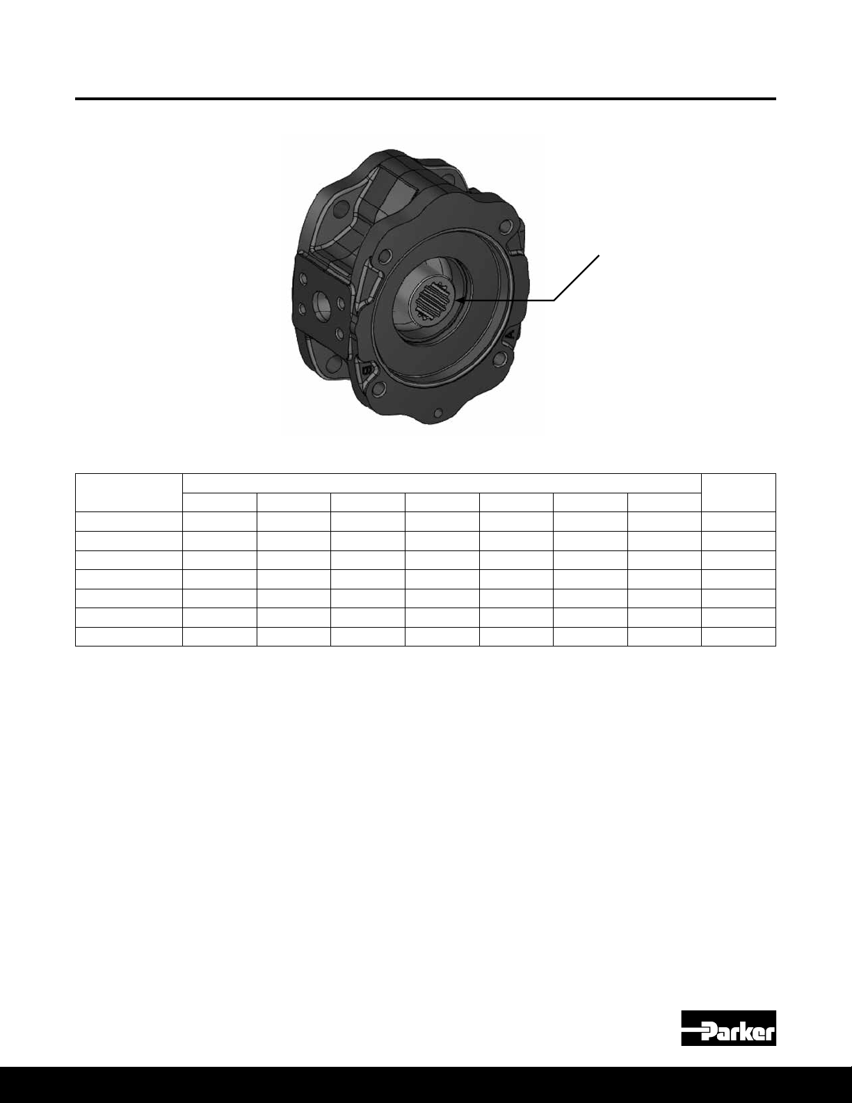
1. Identify the pump from the information on the data tag. See Figure 1.
2. Drain uid from housing. Fluid drained from pump should be disposed of properly.
3. Mount pump in xture to prevent movement while removing the main housing
bolts (#1).
4. Remove the four bolts holding the compensator assembly to the pump housing.
Additional uid may drain out of the passages when the compensator is removed.
For compensator disassembly instructions, see Compensator Disassembly
Procedures section.
5. Remove the four bolts (#1) attaching the port block to the main housing.
6. Carefully remove the port block (#3) assembly. Except for the 18 & 28cc pump,
the control piston guide (#14) and bias guide (#11) are threaded with Loctite into
the block (#3). Use caution to avoid dropping the port plate (#9). Note the location
of the bias spring (#13) and piston (#12) assembly and the control piston (#15)
assembly. The control piston (#15), bias piston (#12), and bias spring (#13) may
remain in the pump when the port block is removed. Remove these items from
inside the pump if they remained in the pump when the port block was removed.
Remove and discard the white Teon O-rings (#8) on the port block. These seals
should be replaced every time the pump is disassembled.
NOTE: For rotation change, do not disassemble further. See Rotation
Change Procedure.
7. For the 60-140cc pumps, remove the tapered roller bearing cone (#18) and
shims (#17).
Parker Hannin Corporation
Hydraulic Pump and Power Systems Division
Marysville, Ohio USA
Figure 1 Pump Data Tag
35
Page 36

Bulletin HY28-2708-02/SVC/EN | July 2019
Pump Service Procedures
Medium Pressure Axial Piston Pumps
P1/PD B-mod Service Information
Pump Disassembly Procedure
(Continued)
8. Position the pump horizontally and remove the rotating group. Avoid
separating the pistons (#27) from the barrel (#23) if possible. This will assist
in identifying damage between an individual piston and barrel bore during
component inspection.
NOTE: If completing a seal change or complete overhaul on a 45cc pump or
larger, turn the housing over and remove the seal retainer snap ring (#40) and
shaft seal (#39) from the housing before moving to step 9.
NOTE: For shaft change only on 45cc pumps or larger, no further
disassembly is required. Proceed to Step 7 of the assembly procedure.
9. Remove the cam (#29) from the housing by tilting it and carefully extracting it
from the pump housing. See Figure 2.
Large Pocket
Pressure Control
Side of Pump
Figure 2
10. For sizes 60-140cc remove the front tapered roller bearing cone (#32). If there
is excessive wear or damage, remove the tapered roller bearing cup (#33)
from the bottom of the housing.
11. Remove the cam bearing screws (#30) and two cam bearings (#31).
12. Remove the housing snap ring (#43) and shaft bearing assembly (#32).
13. If completing a seal change or complete overhaul, turn the housing over
and remove the seal retainer snap ring (#40) and shaft seal (#39) from the
housing. For a 45cc pump or larger, this step was already completed as part
of step 8.
14. If there is excessive wear on the port block bearing (#18) (bushing for sizes
18, 28 & 45), remove the bearing or bushing from the port block (#3).
36
Parker Hannin Corporation
Hydraulic Pump and Power Systems Division
Marysville, Ohio USA
Page 37

Bulletin HY28-2708-02/SVC/EN | July 2019
Pump Inspection Procedures
Medium Pressure Axial Piston Pumps
P1/PD B-mod Service Information
Pump Inspection Procedures
1. Carefully clean and dry all parts prior to inspection.
2. Examine piston diameters for scratches or gouges. If any piston is severely
damaged, note which piston bore it came out of. Extra attention should be
given to that bore in Step 4.
3. Check end play of piston shoe assembly. Check bottom surface of the shoes
for damage or excessive scratching. The shoe surface should be square and
at. Measure the depth of the pocket of the shoe. Shoes may be lapped as a
set if the pocket depth is within the allowable limits. Conrm pocket depth after
lapping to ensure it is still within the limits.
4. Examine the bores in the cylinder barrel (#23) for scratches or gouges. If
there are any scratches or gouges, the barrel needs to be replaced. Examine
the barrel running face for scratches or gouges.
5. Examine the port plate (#9) for scratches, gouges, pitting, material removal
or discoloration. It can be lapped lightly if the face is only lightly scratched;
otherwise, it should be replaced. Refer to the chart for lapping limits.
6. Examine the retainer plate (#26) in the area of contact with the piston shoes.
Any marks beyond light polishing indicate that replacement is necessary.
Check the surface of the spherical area of the retainer plate and the spherical
guide washer (#25). Inspect the back surface of the spherical guide washer
where the load pins (#24) make contact. If there are excessive or uneven
indentations, the spherical guide washer (#24) needs replaced.
7. Examine the top and bottom surfaces of the cam (#29). If scratches or
gouges appear to penetrate the surface treatment, then the cam (#29) should
be replaced.
8. Inspect the cam bearings (#31). They cannot be reworked and should be
replaced if worn through the Teon surface coating.
9. Both the bias piston (#12) and the control piston (#15) should move freely in
their respective guides. The pistons and bores should be free of scratches or
gouges. If not, they need to be replaced.
10. The seal area of the drive shaft (#28) should be smooth and be free of marks
from seal wear. For the larger pumps with tapered roller bearings, the bearing
surfaces should not have any indication of the bearing cone (#32) spinning
on the shaft. Keyed shafts should be inspected for signs of brinelling and
damage to the key area. If replacing the keyed shaft, then the key should be
replaced as well. Spline shafts may have a contact wear pattern, but should
not show excessive wear on the spline area.
11. Spin the shaft bearing (#32). It should not have any signs of roller
spalling, brinelling, or discoloration. It should rotate freely without binding
or rough feel.
Parker Hannin Corporation
Hydraulic Pump and Power Systems Division
Marysville, Ohio USA
37
Page 38

Bulletin HY28-2708-02/SVC/EN | July 2019
Component Rework Limits
Item No 9 13 21 23 27
Medium Pressure Axial Piston Pumps
P1/PD B-mod Service Information
Component Port Plate Bias spring
018 2.97mm
028 3.98mm
045 4.98mm
060 4.98mm 112.0mm 58.5 mm 03E-94036-0
075/085 5.98mm
100 6.48mm
140 6.48mm
Minimum
allowable
thickness after
Tolerances
lapping
0.8 mm minimum
allowable surface
nish
03E-94430-0
78.3 mm
03E-94393-0
87.5 mm
03E-94356-0
116.4 mm
03E-93151-0
5.57 in
(141.5 mm)
03E-93801-0
6.87 in
(174.6 mm)
03E-93963-0
8.36 in
(212.3 mm)
Free Height:
± 0.020 in
(± 0.51mm)
Barrel hold down
spring
787635
41.4 mm
03E-94387-0
39.5 mm
03E-94350-0
48.3 mm
03E-93145-0
2.50 in
(63.7 mm)
03E-93795-0
2.84 in
(72.2 mm)
03E-93959-0
2.70 in
(68.6 mm)
Free Height:
+/- 0.2mm
Barrel Part
03E-94717-0
03E-94375-0
03E-94338-0
03E-93129-0
03E-93783-0
03E-93242-0
Max material
to be removed
by lapping
is 0.0002 in
(0.0051mm)
Number
Piston and shoe assembly
Sold in sets only
789519
Max end play 0.10 mm
Min shoe ange
Thickness 2.97 mm
S2E-18415-0
Max end play 0.07 mm
Min shoe ange
Thickness 3.98 mm
S2E-184130-0
Max end play 0.10 mm
Min shoe ange
Thickness 4.98 mm
03E-94036-0
Max end play
0.004 in (0.10 mm)
Min Shoe Flange
Thickness
0.233 in (5.91 mm)
S2E-17003-0
Max End Play
0.004 in (0.10 mm)
Min Shoe Flange
Thickness
0.233 in (5.91 mm)
S2E-17912-0
Max End Play
0.005 in (0.13 mm)
Min Shoe Flange
Thickness
0.252 in (6.41 mm)
S2E-17323-0
Max end play
0.005 in (0.13 mm)
Min shoe ange
Thickness
0.252 in (6.41 mm)
End play between piston and shoe should
not exceed values shown.
Total material allowed to be removed
from shoe face when lapping is 0.003 in
(0.076mm)
Table 2 - Component Rework Information
38
Parker Hannin Corporation
Hydraulic Pump and Power Systems Division
Marysville, Ohio USA
Page 39

Bulletin HY28-2708-02/SVC/EN | July 2019
three measurements.
pump.
three pins to slots in barrel spline. Petroleum jelly can be used to hold pins in
place while installing remaining parts. (Figure 4) Place barrel on fixture with
pin side down. Install backup washer and hold down spring. Compress
spring in press and install snap ring. Caution: Make sure snap ring is
properly seated in groove prior to removing barrel from press.
018, 028, 045 Assembly Procedures
Medium Pressure Axial Piston Pumps
P1/PD B-mod Service Information
Pump Assembly Procedures
Any seals removed during disassembly, including the shaft seal, should be
replaced. For major overhauls, all plugs should be removed and their O-rings
replaced.
Assembly should be performed in a clean work environment.
Do not use bearing grease during installation. Grease does not dissolve in
hydraulic oil and may plug orices or lters in the system. Clean petroleum jelly
is preferred to lubricate O-rings and seals and to adhere parts for assembly.
NOTE: For uids other than petroleum based hydraulic oil, ensure that the
petroleum jelly is compatible with the uid. If not compatible, another product
should be used instead.
1. Make sure new parts are clean, or if re-using parts, make sure they are
thoroughly cleaned.
2. Inspect all bearing surfaces and seal areas to ensure that they are free from
nicks, dings, scratches, or rust.
3. For the 45cc pump, skip step 3. For the 18 and 28cc pumps, turn the housing
over. Use installation tool T1 and press the shaft seal (#39) in the seal bore.
Install the snap ring (#40) into the groove in the housing seal bore.
4. Install the cylindrical shaft bearing (#32) onto the pump shaft (#28). It is a slip
t for the 18 and 28cc pumps. For the 45cc pump, use tool T2 to install the
shaft bearing onto the pump shaft.
5. Install the external retaining ring (#42) to secure the bearing in place on the
shaft. For the 45cc pump, use tool T3 to install the shaft seal (#39) over the
shaft. Tool T3 will help protect the shaft seal from being damaged by the
splines during shaft installation. For all three sizes, insert the shaft assembly
into the pump housing with the bearing sliding into the bearing diameter in
the housing. Be sure not to cut or damage the shaft seal while installing the
shaft. For the 28cc pump, tool T3 can be used to protect the shaft seal from
damage from the splines of the shaft. For the 18 and 28cc pumps, install the
internal retaining ring (#43) into the housing. For the 45cc pump, install the
shaft seal snap ring (#40) into the groove in the housing seal bore.
6. If the barrel hold down spring (#21) was removed during the disassembly
process, place the barrel (#23) on xture with piston bores down. Install the
back-up washer (#22), hold down spring (#21), and second back-up washer
(#22). On the 45cc pump and larger, there is only one back-up washer (#22).
Compress the spring in a press and install the snap ring (#20). Next, rotate
the barrel assembly so that the piston bores face up. Slide tool T6 up through
the center of the barrel from the bottom side. Place the three barrel pins (#24)
into the three slots in the barrel spline as shown in Figure 3. In lieu of tool
T6, petroleum jelly can be used to hold the pins in place while installing the
remaining parts.
Parker Hannin Corporation
Hydraulic Pump and Power Systems Division
Marysville, Ohio USA
CAUTION: Make sure the snap ring (#20) is properly seated in its groove prior to
removing the barrel assembly from the press.
Figure 3
39
Page 40

Bulletin HY28-2708-02/SVC/EN | July 2019
13. Apply a light film of oil into the piston bores. Lightly lubricate the spherical
surface of the guide ball. Install the nine pistons into the bores in the hold
down plate. Install the spherical guide ball into the hold down plate. While
holding the guide ball against the hold down plate, install the pistons into the
barrel.
14. Install the locating pin on the port block face.
15. Apply Loctite Primer Grade T to guide threads and allow to dry. Install
unlubricated o-rings on the control guide and bias guide. Apply Loctite 271to
guide threads. For left hand rotation the bias guide is installed nearest to the
dowel pin (figure 5A.) For right hand rotation the control guide is installed
nearest to the dowel pin (figure 5B.) Torque the control and bias guides as
Figure 5A
Port Block with Left
Hand Configuration
Figure 5B
Port Block with Right
Hand Configuration
specified in Chart 3.
Locating Pin
Bias Piston
Guide
Control Piston
Guide
018, 028, 045 Assembly Procedures
Medium Pressure Axial Piston Pumps
P1/PD B-mod Service Information
Pump Assembly Procedures
(Continued)
7. Apply a light oil lm into the piston bores of the barrel (#23). Lightly lubricate
the spherical surface of the spherical retaining plate washer (#25). Install the
nine pistons (#27) into the bores in the retaining plate (#26). Assemble the
spherical retaining plate washer into the retaining plate. While holding the
spherical washer against the retaining plate, slide the pistons into the barrel.
8. Install the two port block locating/dowel pins (#17) and the one port plate
locating pin (#7) into their respective locations on the port block (#3) face.
9. Install the port block control ow set screw (#6) in the proper location
depending on pump rotation. For proper location, see Figure 11 in the
rotation change section. The set screw should be installed in the passage
on the same side of the port block as the control piston.
10. For the 45cc pump, install unlubricated O-rings (#10) onto the control piston
guide (#14) and bias guide (#11). Next, apply Loctite Primer SF 194500 or
similar to the control piston guide and bias guide threads and allow it to
dry. The primer usually dries in about three minutes. Next, apply Loctite 263
to the guide threads. For CCW rotation, install the bias guide (#11) nearest
to the locating pin (#17). See Figure 5A. For CW rotation, install the control
piston guide (#14) nearest to the locating pin (#17). See Figure 5B. Torque the
guides to 105 ft lbs. For the 18 and 28cc pumps, press the guides into the
port block.
NOTE: Torquing needs to be done in less than two minutes; otherwise, the
Loctite will set too soon and the guides will not be able to be fully torqued.
045 Picture
11. Apply a light oil lm to the control piston (#15), and install it into the control
guide (#14) bore. Apply a light oil lm to the bias piston (#12). Install the bias
spring (#13) over the bias guide (#11) bore, and then slide the bias piston into
the bias guide bore.
12. For side ported non thru drive pumps, install the ripple chamber set screw
(#16) and plug (#19) and torque per the torque table values. For CW units, the
set screw is installed nearest to the locating pin. For CCW units, the set screw
is installed furthest from the locating pin. See Figure 6. Pumps that are end
ported or have a thru drive do not have a ripple chamber.
Figure 5A
Port Block with Left
Hand Conguration
40
Figure 5B
Port Block with Right
Hand Conguration
Parker Hannin Corporation
Hydraulic Pump and Power Systems Division
Marysville, Ohio USA
Page 41

Bulletin HY28-2708-02/SVC/EN | July 2019
Note Slot Length
and Quantity
Industrial Port Plates
Mobile Port Plates
CCW Port Plates CW Port Plates Back Surface
Locating Pin Slot
018, 028, 045 Assembly Procedures
Medium Pressure Axial Piston Pumps
P1/PD B-mod Service Information
Pump Assembly Procedures
(Continued)
Table 3
Pump Housing bolt torque
018 52 ft lbWs (70 Nm)
028 52 ft lbs (70 Nm)
045 63 ft lbs (85 Nm)
Ripple chamber set screw
location - CCW
Ripple chamber set screw
location - CW
Dowel Pin
Figure 6 - Port Block Assembly with Ripple Chamber
13. Install the port block bushing (#18) into the port block face using tool T5.
14. Apply a light layer of petroleum jelly to the back surface of the port plate (#9).
Install it on the port block (#3), lining up the slot on the port plate with the port
plate locating pin (#7). See Figure 7.
15. Install the large O-ring (#4) into the groove on the port block (#3). Install the
three Teon O-rings (#8) on the pressure communication ports on the port
block.
16. Install the control ow housing set screw (#34) into the proper passage. For
proper location, see Figure 12 in the rotation change section.
17. Place the cam bearings (#31) in the cradle area of the housing. Apply two
drops of Loctite 243 (use sparingly) to the cam bearing screw (#30) threads
and install the screws to hold the cam bearings in place. Torque the screws
Parker Hannin Corporation
Hydraulic Pump and Power Systems Division
Marysville, Ohio USA
per the torque table on page 7.
Figure 7
41
Page 42

Bulletin HY28-2708-02/SVC/EN | July 2019
018, 028, 045 Assembly Procedures
Pump Assembly Procedures
(Continued)
NOTE: Make sure the Loctite does not get in the orice hole in the cam
18. Place thin lm of clean oil on the cam bearing (#31) surfaces. Install the cam
NOTE: The large pocket on the bottom surface of the cam must be on the
19. Position the pump horizontally and install the rotating group into the pump
20. Carefully install the assembled port block (#3) on the pump housing. Press the
21. On the 18 & 28cc units, install the M6x6 set screw with orice (#38) into the
22. Install any boss plugs (#2, 5, 36 & 37) that were removed during disassembly.
23. Install ve O-ring seals and assembled compensator (#41) on the side of the
Medium Pressure Axial Piston Pumps
P1/PD B-mod Service Information
Figure 8 - Cam Bearings
bearing screws.
(#29) in the housing. For the 45cc pump, the cam must be tilted to permit
entry into the housing. See Figure 2.
same side as the three pressure communication holes on the main housing.
Cam assembly is not affected by pump rotation direction.
housing over the pump shaft (#28) and against the cam (#29) with tool T6 in
place in the center of the barrel (#23). Remove tool T6 as the barrel is slid
onto the shaft. This ensures all three barrel pins (#24) are held in place as the
rotating group is installed on the shaft.
port block to compress the bias spring (#13) and install the four housing bolts
(#1). Tighten the bolts in a cross pattern to ensure that the port block does
not get cocked on the housing. When the port block is seated on the housing,
torque the bolts in a cross pattern per the values in the Table 3.
BG port in the housing (#35) if it was removed during disassembly.
pump housing. Tighten the compensator bolts hand tight, and then torque the
bolts per the values in the torque table on page 13.
42
Parker Hannin Corporation
Hydraulic Pump and Power Systems Division
Marysville, Ohio USA
Page 43

Bulletin HY28-2708-02/SVC/EN | July 2019
060, 075, 085, 100, 140 Assembly Procedures
Medium Pressure Axial Piston Pumps
P1/PD B-mod Service Information
Pump Assembly Procedures
Any seals that were removed during disassembly, including the shaft seal, should be
replaced. For major overhauls, all plugs should be removed and their O-rings replaced.
Assembly should be performed in a clean work environment.
Do not use bearing grease during installation. Grease does not dissolve in hydraulic
oil and may plug orices or lters in the system. Clean petroleum jelly is preferred to
lubricate O-rings and seals and to adhere parts for assembly.
NOTE: For uids other than petroleum based hydraulic oil, insure that the petroleum
jelly is compatible with the uid. If not compatible, another product should be used
instead.
1. Make sure new parts are clean, or if re-using parts, make sure they are
thoroughly cleaned.
2. Inspect all bearing surfaces and seal areas to ensure that they are free from
nicks, dings, scratches, or rust.
3. Use tool T7 to press the front shaft bearing cup (#33) into the bottom of
the housing. Make sure the cup is seated rmly against the bottom of the
housing.
4. Turn housing over and use tool T1 to press the shaft seal (#39) into the seal
bore of the housing. Install the snap ring (#40) into the groove in the seal
bore.
5. Use tool T8 to press the rear shaft bearing cup (#18) into the port block (#3).
Insure that the cup is seated rmly against the bottom of the casting. Install
the front shaft bearing cone (#32) and shaft (#28) into the housing. Tool T3
can be used to help protect the shaft seal from damage from the splines
when installing the shaft. Install the rear shaft bearing cone (#19) on the shaft.
6. Mount the port block (#3) onto the housing (#35) using the four socket head
cap screws (#1), and tighten to 20 ft-lbs +/- 1 ft-lb.
7. Position the pump so the shaft end is up and lay a parallel bar on the pump
mounting ange pilot. Press down on the shaft and rotate the shaft 3-5
times then measure the height of the shaft end to the parallel bar using dial
calipers or a dial indicator. Grasp the shaft and pull it up and rotate the shaft
3-5 times. Measure the height of the shaft end to the parallel bar. See Figure
9. Subtract the larger number from the smaller to get the gap differential.
Repeat this step three times, and calculate the average gap differential of the
three measurements.
NOTE: If the shaft slips or falls, this step must be repeated to get an accurate
measurement.
8. Based on the average gap differential, use the shim chart to determine the
correct shim (#17) to install in the pump.
9. Verify the correct shim (#17) was selected by rebuilding the pump with the
shaft bearings, shaft, and selected shim. Install the shaft bearing cone (#32).
Next, insert the shaft (#28) into the housing (#35) through the cone. Place the
shim over the shaft, and then install the port block bearing cone (#19) over
the shaft. Finally, install the port block (#3) onto the housing and pull on the
shaft to check for any shaft end play or excessive movement.
10. Remove the port block (#3) from the housing. Then remove the port block
bearing cone (#19) and shim (#17) and continue with the rest of the assembly.
Parker Hannin Corporation
Hydraulic Pump and Power Systems Division
Marysville, Ohio USA
43
Page 44

Bulletin HY28-2708-02/SVC/EN | July 2019
Axial movement
060, 075, 085, 100, 140 Assembly Procedures
Pump Assembly Procedures
(Continued)
Medium Pressure Axial Piston Pumps
P1/PD B-mod Service Information
Figure 9
Measured Differential
Minimum Maximum 060/075/085 100 140
3.07 mm (.121 in) 3.12 mm (.123 in) 3.04 mm (.1196 in) 03E-95262-0 03E-95268-0 03E-95265-0
3.15 mm (.124 in) 3.22 mm (.126 in) 3.12 mm (.1228 in) 03E-95263-0 03E-95269-0 03E-95266-0
3.23 mm (.127 in) 3.29 mm (.129 in) 3.20 mm (.1259 in) 03E-95264-0 03E-95270-0 03E-95267-0
3.30 mm (.130 in) 3.36 mm (.132in) 3.28 mm (.1291 in) 03E-93180-0 03E-94148-0 03E-93260-0
3.37 mm (.133 in) 3.44 mm (.135 in) 3.36 mm (.1323 in) 03E-93566-0 03E-94149-0 03E-93970-0
3.45 mm (.136 in) 3.51mm (.138 in) 3.44 mm (.1354in) 03E-93567-0 03E-94150-0 03E-93971-0
3.52 mm (.139in) 3.62 mm (.142 in) 3.52 mm (.1386 in) 03E-93568-0 03E-94151-0 03E-93972-0
3.63 mm (.143 in) 3.70 mm (.145 in) 3.60 mm (.1417 in) 03E-93569-0 03E-94152-0 03E-93973-0
3.71 mm (.146 in) 3.77 mm (.148 in) 3.68 mm (.1449 in) 03E-93570-0 03E-94153-0 03E-93974-0
3.78 mm (.149 in) 3.85 mm (.151 in) 3.76 mm (.1480 in) 03E-93571-0 03E-94154-0 03E-93975-0
3.86 mm (.152 in) 3.92 mm (.154 in) 3.84 mm (.1512 in) 03E-93572-0 03E-94155-0 03E-93976-0
3.93 mm (.155 in) 4.00 mm (.157 in) 3.92 mm (.1539 in) 03E-93573-0 03E-94156-0 03E-93977-0
4.01 mm (.158 in) 4.10 mm (.161 in) 4.00 mm (.1575 in) 03E-93574-0 03E-94157-0 03E-93978-0
4.11 mm (.162 in) 4.18 mm (.164 in) 4.08 mm (.1606 in) 03E-93575-0 03E-94158-0 03E-93979-0
4.19 mm (.165 in) 4.25 mm (.167 in) 4.16 mm (.1638 in) 03E-93576-0 03E-93864-0 03E-93980-0
Shim
Thickness
Shim Kits: S2E-18591-0K S2E-18640-0K S2E-18527-0K
Displacement
Table 4 - Shim Thickness Selection
44
Parker Hannin Corporation
Hydraulic Pump and Power Systems Division
Marysville, Ohio USA
Page 45

Bulletin HY28-2708-02/SVC/EN | July 2019
13. Apply a light film of oil into the piston bores. Lightly lubricate the spherical
surface of the guide ball. Install the nine pistons into the bores in the hold
down plate. Install the spherical guide ball into the hold down plate. While
holding the guide ball against the hold down plate, install the pistons into the
barrel.
14. Install the locating pin on the port block face.
15. Apply Loctite Primer Grade T to guide threads and allow to dry. Install
unlubricated o-rings on the control guide and bias guide. Apply Loctite 271to
guide threads. For left hand rotation the bias guide is installed nearest to the
dowel pin (figure 5A.) For right hand rotation the control guide is installed
nearest to the dowel pin (figure 5B.) Torque the control and bias guides as
Figure 5A
Port Block with Left
Hand Configuration
Figure 5B
Port Block with Right
Hand Configuration
specified in Chart 3.
Locating Pin
Bias Piston
Guide
Control Piston
Guide
060, 075, 085, 100, 140 Assembly Procedures
Medium Pressure Axial Piston Pumps
P1/PD B-mod Service Information
Pump Assembly Procedures
(Continued)
Table 5
Pump
060
075 /085
100
140
Control and Bias Guide
Torque
105 ± 5 ft-lbs
(142 ± 6.5 Nm)
105 ± 5 ft-lbs
(142 ± 6.5 Nm)
136 ± 6 ft-lbs
(184 ± 8 Nm)
170 ± 6 ft-lbs
(203 ± 8 Nm)
11. If the barrel hold down spring (#21) was removed, place the barrel (#23) on
xture with pin side down and install the back-up washer (#22) and hold
down spring. Compress the spring in a press and install the snap ring (#20).
Next, rotate the barrel assembly so that the piston bores face up. Place the
three barrel pins (#24) into the three slots in the barrel spline as shown in
Figure 3. Petroleum jelly can be used to hold the pins in place while installing
the remaining parts.
CAUTION: Make sure the snap ring (#20) is properly seated in the groove
prior to removing the barrel (#23) from the press.
12. Apply a light oil lm into the piston bores of the barrel (#23). Lightly lubricate
the spherical surface of the spherical retaining plate washer (#25). Install
the nine piston bores down (#27) into the bores in the retaining plate (#26).
Assemble the spherical retaining plate washer into the retaining plate.
While holding the spherical washer against the retaining plate, slide the
pistons into the barrel.
13. Install the port block locating/dowel pin (#7) into the port block (#3) face.
14. Install the port block control ow set screw (#6) in the proper location
depending on pump rotation. For proper location, see Figure 11 in the
rotation change section. The set screw should be installed in the passage
on the same side of the port block as the control piston.
15. Install unlubricated O-rings (#10) onto the control piston guide (#14) and
bias guide (#11). Apply Loctite Primer SF 194500 to the control piston guide
and bias guide threads and allow it to dry. This usually take about three
minutes. Apply Loctite 263 to the guide threads. For CW rotation, install the
control piston guide (#14) nearest to the locating pin. See Figure 10A.
For CCW rotation, install the bias guide (#11) nearest to the locating pin (#7).
See Figure 10B. Torque the guides per the values specied in the Table 4.
16. Apply a light oil lm to the control piston (#15), and install it into the control
Port Block with Left
Hand Conguration
guide (#14) bore. Apply a light oil lm to the bias piston (#12). Install the bias
spring (#13) over the bias guide (#11) bore, and then slide the bias piston into
the bias guide bore.
17. Install the control ow housing set screw (#34) into the proper passage.
For proper location, see Figure 12 in the rotation change section.
18. Apply a light layer of petroleum jelly to the back surface of the port plate (#9)
and place it on the port block (#3), lining up the slot on the port plate with the
locating pin (#7). See Figure 7.
Parker Hannin Corporation
Hydraulic Pump and Power Systems Division
Marysville, Ohio USA
Figure 10A
45
Figure 10B
Port Block with Right
Hand Conguration
Page 46

Bulletin HY28-2708-02/SVC/EN | July 2019
060, 075, 085, 100, 140 Assembly Procedures
Medium Pressure Axial Piston Pumps
P1/PD B-mod Service Information
Pump Assembly Procedures
(Continued)
Table 6
Pump Housing Bolt Torque
060
075 / 085
100
140
100 ± 4 ft-lbs
(135.6 ± 5 Nm)
100 ± 4 ft-lbs
(135.6 ± 5 Nm)
170 ± 5 ft-lbs
(229 ± 7 Nm)
205 ± 5 ft-lbs
(278 ± 7 Nm)
19. Install the large O-ring (#4) into the groove on the port block (#3). Install the
three Teon O-rings (#8) on the pressure communication ports on the port
block.
20. Place the cam bearings (#31) in the cradle area of the housing. The chamfer
on the back of the bearing must face the outer wall of the housing. Use
Loctite Primer Grade “T” or other suitable primer on the cam bearing screws
(#30) and mating housing threads. Allow the primer to dry. This usually take
ten minutes. Apply Loctite 243 (use sparingly) to the cam bearing screw
threads and install the screws to hold the cam bearings in place. Torque the
screws per torque table values on page 9.
21. Place thin lm of clean oil on the cam bearing (#31) surfaces. Install the cam
(#29) in the housing. The cam must be tilted to permit entry into the housing.
See Figure 2.
NOTE: The large pocket on the bottom surface of the cam must be on the
same side as the three pressure communication holes on the main housing.
Cam assembly is not affected by pump rotation direction.
22. Position the pump horizontally and install the rotating group into the pump
housing over the pump shaft (#28) and against the cam (#29).
23. Place the bearing shim (#17) and port block bearing cone (#19) on around
the drive shaft (#28).
24. Carefully install the assembled port block (#3) on the pump housing. Press
the port block to compress the bias spring (#13) and install the four housing
bolts (#1). Tighten the bolts in a cross pattern to ensure that the port block
does not get cocked on the housing. When the port block is seated on the
housing, torque the bolts in a cross pattern per the values in Table 6.
25. Install any boss plugs (#2, 5, 16, 36 & 37) that were removed during
disassembly.
26. Install the ve O-ring seals and assembled compensator (#41) on the side
of the pump housing. Tighten the compensator bolts hand tight, and then
torque bolts per torque table on page 13.
46
Parker Hannin Corporation
Hydraulic Pump and Power Systems Division
Marysville, Ohio USA
Page 47

Bulletin HY28-2708-02/SVC/EN | July 2019
T2 Front Bearing P1/PD45 Installation Tool
Assembly Tools
Medium Pressure Axial Piston Pumps
P1/PD B-mod Service Information
T1 Seal Installation Tool
A
DIA
DIA
18.5 mm
(0.728 in)
D
8.0 mm
(0.3150 in)
B
DIA
C
U-CUT
133 mm
(5.250 in)
3.0 mm RADIUS
(.12 in)
1.5 mm x 45˚ TYP.
(.06 in X 45˚ )
31.2 mm
(1.250 in)
DIA.
Pump Model Part No A B C D
018 2.250 in 1.62 in 1.18 in 0.406 in
028 2.250 in 2.00 in 1.375 in 0.447 in
060 / 075 / 085 213-0-004194 2.750 in (69.9 mm) 1.980 in (50.3 mm) 1.375 in (34.9 mm) 0.800 in (20.3 mm)
100 213-0-004208 2.50 in (63.5 mm) 2.230 in (56.6 mm) 1.703 in (43.3 mm) 0.550 in (14.0 mm)
140 213-0-004199 3.375 in (85.7 mm) 2.780 in (70.6 mm) 2.10 in (53.4 mm) 0.750 in (19.1 mm)
T2 Front Bearing
Installation Tool (45 only)
89.75 mm
(3.53 in)
29.92 mm
(1.178 in)
Parker Hannin Corporation
Hydraulic Pump and Power Systems Division
Marysville, Ohio USA
0 mm0.02
7 in
25.40 mm
(1.00 in)
)87.0(
177.80 mm
(7.00 in)
50.80 mm
(2.00 in)
47
Page 48

Bulletin HY28-2708-02/SVC/EN | July 2019
Assembly Tools
Medium Pressure Axial Piston Pumps
P1/PD B-mod Service Information
T3 Seal Guard
E
DIA.
(+/- 0.002 in)
+/- 0.05mm
BLEND RADIUS
& POLISH O.D.
C
D
A
B
30˚
F
DIA BORE
+0.05 / -0.00mm
(+0.002 / - 0.000 in)
Pump Model Part Number A B C D E F
018
(“01”, “02”, “04”
Shafts)
018
(“06” Shaft)
028 / 045
( “01”, “02”, “04”
Shafts)
018 / 028 / 045
(“08” Shaft)
060 / 075 / 085 213-0-004195
100 SAE 213-0-004206
100 ISO 213-0-004207
140 SAE 213-0-004200
140 ISO 213-0-004201
3.00 in
(76.20 mm)
3.00 in
(76.20 mm)
3.00 in
(76.20 mm)
3.00 in
(76.20 mm)
4.25 in
(108 mm)
4.25 in
(108 mm)
4.50 in
(114 mm)
4.25 in
(108 mm)
4.50 in
(114 mm)
2.00 in
(50.80 mm)
2.00 in
(50.80 mm)
2.00 in
(50.80 mm)
2.00 in
(50.80 mm)
2.25 in
(57.1 mm)
2.78 in
(70.6 mm)
3.00 in
(76.2 mm)
2.78 in
(70.6 mm)
3.00 in
(76.2 mm)
0.75 in
(19.05 mm)
0.75 in
(19.05 mm)
0.75 in
(19.05 mm)
0.75 in
(19.05 mm)
1.00 in
(25.4 mm)
1.00 in
(25.4 mm)
0.88 in
(22.4 mm)
1.00 in
(25.4 mm)
0.88 in
(22.4 mm)
15°
15°
15°
15°
10°
10°
15°
10°
15°
1.135 in
(28.82 mm)
1.135 in
(28.82 mm)
1.50 in
(38.10 mm)
1.135 in
(28.82 mm)
1.373 in
(34.90 mm)
1.703 in
(43.26 mm)
1.703 in
(43.26 mm)
2.088 in
(53.04 mm)
2.088 in
(53.04 mm)
0.805 in
(20.45 mm)
0.66 in
(16.76 mm)
1.024 in
(26.00 mm)
0.885 in
(22.50 mm)
0.885 in
(31.75 mm)
1.5 in
(38.1 mm)
1.577 in
(40.06 mm)
1.751 in
(44.48 mm)
1.970 in
(50.04 mm)
T5 Rear Bushing Installation Tool
(18 thru 45)
38 mm
(1.5 in)
29 mm
(1.14 in)
38 mm
(1.5 in)
B
A
102 mm
(4.0 in)
25 mm
(1.0 in)
Pump Size A B
13 mm
(.5 in)
48
018
028
045
0.146 in
(3.71 mm)
0.157 in
(4.00 mm)
0.157 in
(4.00 mm)
0.772 in
(19.9 mm)
0.85 in
(21.6 mm)
0.95 in
(24.1 mm)
Parker Hannin Corporation
Hydraulic Pump and Power Systems Division
Marysville, Ohio USA
Page 49

Bulletin HY28-2708-02/SVC/EN | July 2019
133 mm
A
(.06 in, X 45˚)
Assembly Tools
T6 Barrel Pin Tool
Pump Size A B C D E
018
028
045
0.795 in
(20.2 mm)
0.902 in
(22.9 mm)
1.059 in
(26.9 mm)
2.84 in
(72.0 mm)
2.95 in
(75.0 mm)
3.35 in
(85.0 mm)
0.756 in
(19.2 mm)
0.862 in
(21.9 mm)
1.020 in
(25.9 mm)
Medium Pressure Axial Piston Pumps
P1/PD B-mod Service Information
2.32 in
(59.0 mm)
2.44 in
(62.0 mm)
2.84 in
(72.0 mm)
1.18 in
(30.0 mm)
1.18 in
(30.0 mm)
1.30 in
(33.0 mm)
T7 Front Bearing Cup Tool (60 thru 140)
DIA
A
DIA
B
Pump Model Part No A B C
060 / 075 / 085 213-0-004192
100 213-0-004204
140 213-0-004197
(0.250 in)
C
6.4 mm
25.4 mm
(1.000 in)
(5.250 in)
3.0 mm RADIUS
(0.12 in)
1.5 mm x 45˚ TYP.
2.812 in
(71.4 mm)
3.623 in
(92.1 mm)
3.687 in
(93.7 mm)
2.60 in
(66.0 mm)
3.390 in
(86.1 mm)
3.515 in
(89.3 mm)
12°
15°
15°
31.2 mm DI
(1.250 in)
Parker Hannin Corporation
Hydraulic Pump and Power Systems Division
Marysville, Ohio USA
49
Page 50

Bulletin HY28-2708-02/SVC/EN | July 2019
133 mm
A.
(.06 X 45 ˚)
DI
Assembly Tools
T8 Rear Bearing Cup Tool (60 thru 140)
6.4 mm
(0.250 in)
25.4 mm
(1.000 in)
Medium Pressure Axial Piston Pumps
P1/PD B-mod Service Information
(5.250 in)
3.0 mm RADIUS
(0.12 in)
A
A
B
DIA
C
1.5 mm x 45 ˚TYP.
Pump Model Part No A B C
060 / 075 / 085 213-0-004193
100 213-0-004205
140 213-0-004198
2.120 in
(53.8 mm)
2.562 in
(65.1 mm)
2.80 in
(71.1 mm)
1.918 in
(48.7 mm)
2.335 in
(59.3 mm)
2.562 in
(65.1 mm)
31.2 mm DI
(1.250 in)
12°
15°
15°
50
Parker Hannin Corporation
Hydraulic Pump and Power Systems Division
Marysville, Ohio USA
Page 51

Bulletin HY28-2708-02/SVC/EN | July 2019
Rotation Change
Medium Pressure Axial Piston Pumps
P1/PD B-mod Service Information
Rotation Change Procedure
A. The B-mod C, L, or AM compensator is the same for both clockwise and
counterclockwise rotation. The compensator position remains unchanged.
B. The port block is bi-rotational, so a new port block is not needed unless the
existing port block is damaged during the rotation change. Therefore, the inlet
and outlet port locations remain the same.
C. For the 45cc and larger pumps, the bias guide (#11) and control guide (#14)
are located into the port block (#3), so they may be difcult to remove without
damaging the guides or port block, so you may want to have extra guides or
port block on hand.
1. Follow the disassembly instructions to the point at which the port plate (#9)
can be accessed. The port plate is rotation dependent and will need to be
changed. See part number tables and select the correct port plate. Use Figure
7 to verify that you have the correct rotation port plate. For the 18, 28, & 45cc
units that are side ported with no thru drive, make sure you select the appropriate ripple chamber port plate because those units will have a ripple chamber in the port block as designated by the “R” in the model code description.
2. Next, the port block control ow set screw (#6) needs to be swapped to the
other passage way as shown in Figure 11. Remove the two boss plugs (#5)
and remove the set screw and install in the other passage. Secure the set
screw with Locktite 243 or equal and torque to 25 in-lbs. Then re-install the
two plugs and torque them to 6 ft-lbs.
CCW set screw location
Parker Hannin Corporation
Hydraulic Pump and Power Systems Division
Marysville, Ohio USA
CW set screw location
Figure 11 – Port Block Control Flow Plug Location
3. For 18, 28, 45cc units with ripple chambers, the rippler chamber set screw
(#16) will need to be relocated to the opposite side as show in Figure 6 in the
18, 28, & 45cc assembly procedures. There will only be ripple chambers on
side ported units that do not have a thru drive. Torque the ripple chamber set
screw per the torque values in the torque table on page 6 or 7.
51
Page 52

Bulletin HY28-2708-02/SVC/EN | July 2019
Rotation Change
Medium Pressure Axial Piston Pumps
P1/PD B-mod Service Information
Rotation Change Procedure
(Continued)
4. Next, the housing control ow set screw (#34) will need to be relocated to
the other control ow passage as shown in Figure 12. Torque the set screw
to 70 in-lbs.
CW set screw locationCW set screw locationCCW set screw location
Figure 12 – Housing Control Flow Plug Location
5. For the 18 & 28cc pump, the control guide (#14) and bias guide (#11) are the
same, so only the locations of the control piston (#15) and bias piston (#12)
and spring (#13) need to be swapped.
6. For the 45cc units and larger, the bias guide (#11) and control guide (#14)
are different, so remove the guides, control and bias pistons, and bias spring
and swap their locations by following Steps 14-15 of the 60-140cc assembly
procedures.
NOTE: The guides are located into the port block, so it may be difcult to
remove them without damaging the port block or the guides themselves.
7. Now the pump can be reassembled per the Assembly Procedures section.
8. Test the pump per the Test Procedure section.
52
Parker Hannin Corporation
Hydraulic Pump and Power Systems Division
Marysville, Ohio USA
Page 53

Bulletin HY28-2708-02/SVC/EN | July 2019
Test Procedure
Medium Pressure Axial Piston Pumps
P1/PD B-mod Service Information
Pump Test Procedure
Test criteria based on hydraulic oil ISO 32 per Parker HF-0 uid specications.
Operating speed: Do not exceed catalog ratings.
Maximum Case pressure: 2 bar (29 psi) absolute or 0.5 bar (7.5 psi) above inlet
pressure.
Minimum inlet pressure: 0.8 bar (11.6 psi) absolute.
Oil temperatures: 120 F +/- 10 F (50 C +/- 5C).
NOTE: Ensure that hydraulic system does not overheat during this test procedure.
1. Mount pump on test xture. Ensure that shaft alignment is within tolerance.
2. Fill pump case with clean oil. Connect uppermost case drain port to reservoir
with no restrictions in between. Insure other case drain ports are properly
plugged and torqued.
3. Connect inlet and outlet lines. Insure that lines are lled with oil. Refer to
the hydraulic schematic test circuit diagrams. For pumps with “L” controls,
connect a suitable pilot line from the “X” port on the pump control to the
outlet pressure line downstream of the non-compensating ow valve (#4), and
install a pressure gauge (#5) in the circuit that will read the pressure in that
pilot line as shown in Circuit #1. For pumps with “AM” controls, connect a
suitable pilot line from the “X” port on the control to a remote pressure relief
valve (#14), and install a pressure gauge (#13) in that line as shown in Circuit
#2.
CAUTION: Make sure a main system safety relief (#7) is installed in the
system between the pump outlet and ow control valve (#4).
4. Conrm direction of rotation for the pump and drive is correct.
5. Reduce the main compensator (Pmax) setting to minimum by turning the
Pmax adjustment screw counter-clockwise until the spring force is not felt.
For pumps with the “L” or “AM” controls, turn the differential adjustment
clockwise until it bottoms out and lock it into position.
6. Set the maximum volume stop (if applicable) to full displacement. If there is a
minimum volume stop back that adjustment all the way out so that the pump
can fully compensate.
7. Start the prime mover and if possible, gradually increase pump speed to 1800
rpm +/- 30 rpm with no load (no pressure on the system load relief valve #6).
8. While under no load, screw in the Pmax adjusting screw until it bottoms out.
9. Break in the pump at the time and pressures listed on the next page. Adjust
the load-relief valve to the pressure listed for the times indicated. After
break-in, loosen the Pmax adjustment screw lock nut and reduce the Pmax
setting to the desired setting by turning the Pmax adjustment screw counterclockwise until the pump pressure gauge reads the desired setting, and then
tighten the lock nut. Next, adjust the system load relief valve to below the
Pmax setting to cause the pump to come on stroke and then back above the
Pmax setting to cause the pump to compensate. Repeat this at least three
times to verify the pump compensates on and off stroke properly.
10. Use steps 10-12 for load sense pumps (“L” control option). Adjust the ow
control valve and load relief valve such that the pump is compensated and the
load pressure gauges reads at least 300-500 psi.
11. Turn the differential screw counter-clockwise until the pump compensates and
the difference between the load pressure gauge and pump outlet pressure
equals the desired differential setting. Tighten the differential screw lock nut to
lock the differential setting in place. The standard factory differential setting is
20 bar (290 psi). The minimum allowable setting is 10 bar (145 psi).
Parker Hannin Corporation
Hydraulic Pump and Power Systems Division
Marysville, Ohio USA
53
Page 54

Bulletin HY28-2708-02/SVC/EN | July 2019
Test Procedure
Medium Pressure Axial Piston Pumps
P1/PD B-mod Service Information
Pump Test Procedure
(Continued)
Test Circuit
1. Test pump
2. Test stand prime mover
3. Pump pressure gauge
4. Non-compensating ow control
5. Load pressure gauge
6. Load relief valve
7. Safety bypass relief valve
8. Main ow meter
9. Case drain pressure gauge
10. Case drain ow meter
11. Filter assembly with bypass
12. Cooler assembly with bypass
13. Remote port gauge
14. Reservoir
NOTE: Items 4 and 5 are required for
load sense pump test. Remote relief
valve and remote pressure gauge not
shown for testing "AM" control option.
12. To determine the pump stand-by pressure, reduce the load relief setting to
zero and conrm there is no pressure in the load sense line. The pump outlet
pressure will be the stand-by pressure.
13. Use steps 13-15 for remote compensator pumps (“AM” control option). Close
the load relief valve to deadhead the pump and adjust the remote relief valve
so that the remote port gauge reads at least 300-500psi, and the difference
between the remote and outlet port gauges is greater than the desired
differential pressure setting.
14. Turn the differential screw counter-clockwise so that the difference between
the remote port pressure and the pump outlet pressure equals the desired
differential pressure. Tighten the differential screw lock nut to lock the
differential setting in place. The standard factory differential setting is 20 bar
(290 psi). The minimum allowable setting is 10 bar (145 psi).
15. To determine the pump stand-by pressure, reduce the remote relief setting to
zero and conrm there is little to no pressure in the remote line. There may be
a little pressure depending on the minimum pressure drop across the remote
relief valve. The pump outlet pressure will be the stand-by pressure.
NOTE: For low Pmax settings (around 1000 psi or less), the differential
pressure for the “L” and “AM” controls may not be adjustable. In this case,
raise the Pmax setting to at least 1500 psi and repeat the pressure differential
adjustment steps.
Time 60 seconds 60 seconds 60 seconds
Pressure 62-69 bar
900-1000 psi
200-207 bar
2900-3000 psi
269-276 bar
3900-4000 psi
3
2
5
EM
9
6
4
1
7
“X”
10
Circuit 1 - Load Sense Test Circuit Diagram
4
7
8
11
3
2
1
8
11
EM
12
14
9
Circuit 2 - Remote Compensator Test Circuit Diagram
54
10
Parker Hannin Corporation
Hydraulic Pump and Power Systems Division
Marysville, Ohio USA
13
12
14
Page 55

Bulletin HY28-2708-02/SVC/EN | July 2019
Test Criteria & Start-up Procedures
P1/PD Performance Test Pass/Fail Specifications
Condition 018 028 045 060 075 085 100 140
Test Speed (rpm) 1800 (For All)
Minimum outlet ow (L/min) at minimum pressure (500 psi) 30.7 46.9 77.2 102 129 148 170 239
Maximum case leakage (L/min) when compensated at 280 bar 5.7 7.6 11 13 15 16 20 23
Maximum input torque (Nm) when compensated at 280 bar 40 40 48 39 58 62 68 91
Minimum outlet ow (L/min) at 260 bar with compensator setting at
280 bar
Allowable load sense ow (L/min) variation from 50 to 260 bar 21.2 30.2 45.5 77 105 105 101 101
Medium Pressure Axial Piston Pumps
P1/PD B-mod Service Information
28.4 44.7 72.7 100 123 143 166 233
Startup Procedure for
New Installations
• Read and understand the installation and start-up manual
HY28-2709-02/P1/EN.
• Identify components and their function.
• Visually inspect components and lines for possible damage.
• Ensure that all necessary ports are properly connected.
• Check reservoir for cleanliness. Drain and clean as required.
• Check uid level and ll as required with ltered uid to a minimum
ISO cleanliness level of 20/18/14.
• Fill pump case with clean oil prior to starting.
• If pump is mounted vertically with the shaft up, bleed the air out the D1
drain port located near the mounting ange.
• Check alignment of drive.
• Check oil cooler and activate it, if included in circuit. Check uid temperature.
• Reduce pressure settings of compensator and relief valve. Make sure accurate
pressure readings can be made at appropriate places.
• If solenoids in system, check for actuation.
• Jog the pump drive. Check for proper shaft rotation. Make sure pump lls
properly.
• Start the pump drive.
• Bleed system of air. Recheck uid level.
• Cycle unloaded machine at low pressure and observe actuation
(at low speed, if possible).
• Increase pressure settings gradually in steps. Check for leaks in all lines
especially in pump and motor inlet lines.
• Make correct pressure adjustments.
• Gradually increase speed. Be alert for trouble as indicated by changes in
sounds, system shocks, and air in uid.
• Equipment is operational.
Parker Hannin Corporation
Hydraulic Pump and Power Systems Division
Marysville, Ohio USA
55
Page 56

Bulletin HY28-2708-02/SVC/EN | July 2019
Trouble Shooting
Component problems and circuit problems are often interrelated. An improper circuit may operate with apparent success but
will cause failure of a particular component within it. The component failure can be the effect, not the cause of the problem.
This general guide is offered to help in locating and eliminating the cause of problems by studying their effects.
Effect of Trouble Possible Cause Fault Which Needs Remedy
Leak in inlet line
Low uid level
Turbulent uid
Noisy pump
Erosion on barrel ports
and port plate
Pressure shocks
Compensator
instability
Air in uid
Cavitation in
rotating group
Misaligned shaft
Mechanical fault in pump
Air in uid See noisy pump above
Cavitation See noisy pump above
Cogging load Mechanical considerations
Worn relief valve Needed repairs
Worn compensator Replace
Slow response in check
valves
Excessive
decompression
energy rates
Barrel blow-off Rotating group worn, excessive case pressure
Line capacitance (line
volume, line stretch, accumulator effects)
Return lines above uid level
Gas leak from accumulator
Excessive pressure drop in the inlet line from a pressurized reservoir
Inlet line strainer acting as air trap
Fluid too cold
Fluid too viscous
Fluid too heavy
Shaft speed too high
Inlet line too small
Inlet strainer too small
Inlet strainer too dirty
Operating altitude too high
Inlet pressure too low
Faulty installation
Distortion in mounting
Axial interference
Faulty coupling
Excessive overhung loads
Piston and shoe looseness or failure
Bearing failure
Incorrect port plate rotation
Eroded or worn parts in the displacement control
Replace or relocate
Improve decompression control
Change line size or lengths
Add or remove hose
Add orice in load sense line
Increase load sense differential pressure
Medium Pressure Axial Piston Pumps
P1/PD B-mod Service Information
Outlet port check valve Relocate check valve further from outlet port
Parker Hannin Corporation
Hydraulic Pump and Power Systems Division
56
Marysville, Ohio USA
Page 57

Bulletin HY28-2708-02/SVC/EN | July 2019
Trouble Shooting
Effect of Trouble Possible Cause Fault Which Needs Remedy
Reduce pressure settings
Reduce speeds
Improper lter maintenance
Filters too coarse
Introduction of dirty uid to system
Reservoir openings
Improper reservoir breather
Improper line replacement
Fluid too thin or thick for operating temperature range
Breakdown of uid with time/temperature/heating effects
Incorrect additives in new uid
Destruction of additive effectiveness with chemical aging
Incorrect parts
Incorrect procedures, dimensions, nishes
Condensation
Faulty breather/strainer
Heat exchanger leakage
Faulty clean-up practice
Water in makeup uid
Recheck case drain ow and repair as required
Fluid too thin
Improper assembly, port timing
Set too low (compared to load or to compensator)
Instability caused by back pressure, worn parts
Set too high (compared to relief)
Worn parts
Select smaller pump displacement
Water turned off or too little ow
Water too hot
Fan clogged or restricted
Efciency reduced by mud or scale deposits
Intermittent hydraulic uid ow
Too little uid
Improper bafes
Insulating air blanket that prevents heat rejection
Heat pickup from adjacent equipment
High wear in pump
Heating of uid
Excessive loads
Contaminant particles
in uid
Improper uid
Improper repair
Unwanted water in uid
Excessive pump leakage
Relief valve
Compensator
Pump too large for
uid needs
Heat exchanger
Reservoir
Medium Pressure Axial Piston Pumps
P1/PD B-mod Service Information
Parker Hannin Corporation
Hydraulic Pump and Power Systems Division
Marysville, Ohio USA
57
Page 58

Bulletin HY28-2708-02/SVC/EN | July 2019
Conversions and Formulas
CONVERSION FACTORS
DEFINITION & UNIT
Displacement in3/rev x 16.387 = cm3/rev cm3/rev x 0.06102 = in3/rev
Flow gpm x 3.78 = L/min L/min x 0.2642 = gpm
Power hp x 0.7457 = kW kW x 1.341 = hp
Torque lb-ft x 1.3567 = Nm Nm x 0.7376 = lb-ft
Pressure lbs/in2 (psi) x 0.06895 = bar bar x 14.50 = lbs/in2 (psi)
lbs/in2 (psi) x 6.895 = kPa kPa x 0.1450 = lbs/in2 (psi)
Weight lb x 0.4536 = kg kg x 2.205 = lbs
Force lb x 4.448 = N N x 0.2248 = lbs
Volume in3 x 16.387 = cm3 cm3 x 0.06102 = in
Area in2 x 6.452 = cm2 cm2 x 0.1550 = in
Length in x 25.4 = mm mm x 0.03937 = in
Temperature degree F-32 = °C 1.8 x C+32 = °F
1.8
Viscosity cSt x 1.0 = mm2/sec mm2/sec x 1.0 = cSt
SSU = cSt x 4.25 + 14 20 cSt = 99 SSU
Medium Pressure Axial Piston Pumps
P1/PD B-mod Service Information
3
2
FLUID POWER FORMULAS
Pump input torque lbs. in. pressure(psi) x displacement (in3/rev)
2� x mech. eff.
Pump input power hp rpm x (in3/rev) x (psi)
395934 x overall eff.
Pump output ow U.S. gpm rpm x (in3/rev) x volumetric eff.
231
Fluid motor speed rpm 231 x ow rate(U.S. gpm) x volumetric eff.
displacement (in3/rev)
Fluid motor torque lbs. in. pressure(psi) x displacement (in3/rev) x mech. eff.
2�
Fluid motor power hp rpm x (in3/rev) x (psi) x overall eff.
395934
(Metric)
Pump input torque Nm pressure(bar) x displacement (cm3/rev)
20� x mech. eff.
Pump input power kW rpm x (cm3/rev) x (bar)
600000 x overall eff.
Pump output ow Lpm rpm x (cm3/rev) x volumetric eff.
1000
Fluid motor speed rpm(min-1 ) (tr/mn) 1000 x ow rate (Lpm) x volumetric eff.
displacement (cm3/rev)
Fluid motor torque Nm pressure(bar) x displacement (cm3/rev) x mech. eff.
20�
Fluid motor power kW rpm x (cm3/rev) x (bar) x overall eff.
600000
58
Parker Hannin Corporation
Hydraulic Pump and Power Systems Division
Marysville, Ohio USA
Page 59

Bulletin HY28-2708-02/SVC/EN | July 2019
Content Changes and Warning
Content Changes
July 2019
- 085 pressure ratings correction
- Miscellaneous part number corrections
- AMT schematic correction
- Amended the differential setting test procedure
Medium Pressure Axial Piston Pumps
P1/PD B-mod Service Information
Warning and Disclaimer
The product information, specications, and descriptions contained in this publication have been compiled
for the use and convenience of our customers from information furnished by the manufacturer; and we can
not, and do not, accept any responsibility for the accuracy or correctness of any description, calculation,
specication, or information contained herein. No such description, calculation, specication, or information
regarding the products being sold has been made part of the basis of the bargain, nor has same created or
amounted to an express warranty that the products would conform thereto. We are selling the goods and
merchandise illustrated and described on this publication on an “as is” basis, and disclaim any implied warranty,
including any warranty of merchantability or warranty of tness for any particular purpose whatsoever, with
respect to the goods and merchandise sold. All manufacturer warranties shall be passed on to our customers,
but we shall not be responsible for special, indirect, incidental, or consequential damages resulting from the
use of any of the products or information contained or described on this publication. Further, we reserve the
right to revise or otherwise make product improvements at any time without notication.
WARNING - USER RESPONSIBILITY
FAILURE OR IMPROPER SELECTION OR IMPROPER USE OF THE PRODUCTS DESCRIBED HEREIN OR RELATED ITEMS CAN CAUSE DEATH,
PERSONAL INJURY AND PROPERTY DAMAGE.
This document and other information from Parker-Hannifin Corporation, its subsidiaries and authorized distributors provide product or system options for further investigation
by users having technical expertise.
The user, through its own analysis and testing, is solely responsible for making the final selection of the system and components and assuring that all performance, endurance,
maintenance, safety and warning requirements of the application are met. The user must analyze all aspects of the application, follow applicable industry standards, and follow
the information concerning the product in the current product catalog and in any other materials provided from Parker or its subsidiaries or authorized distributors.
To the extent that Parker or its subsidiaries or authorized distributors provide component or system options based upon data or specifications provided by the user, the user is
responsible for determining that such data and specifications are suitable and sufficient for all applications and reasonably foreseeable uses of the components or systems.
OFFER OF SALE
The items described in this document are hereby offered for sale by Parker-Hannifin Corporation, its subsidiaries or its authorized distributor. This offer and its accepteance
are governed by the provisions stated in the detailed "Offer of Sale" elsewhere in this document.
Parker Hannin Corporation
Hydraulic Pump and Power Systems Division
Marysville, Ohio USA
59
Page 60

© 2019 Parker Hannin Corporation, all rights reserved
Bulletin HY28-2708-02/SVC/EN
Parker Hannin Corporation
Hydraulic Pump and Power Systems Division
14249 Industrial Pkwy
Marysville, OH 43040 USA
phone 937 644 4435
fax 937 642 3639
www.parker.com/hps
Effective: 07-19
 Loading...