

Parker HMRS08, HMRS11, HMRS18, HMRS15, HMRS24 Assembly And Operating Instructions Manual
...
Modular Electric
HMR Linear Drives
Assembly and Operating Instructions

Modular Electric HMR Linear Drives
Warranty
These operating instructions are subject to changes including changes in technical details with respect to the
information and gures contained herein.
Parker-Hannin GmbH grants no quality or durability guarantees nor any guarantees as to the suitability for specic
purposes. Such guarantees must be expressly agreed upon in writing.
Public statements, recommendations or advertising do not in any way represent quality specications.
The operator's warranty rights require that the operator immediately report any defects and precisely describe said
defects in the complaint. Parker-Hannin GmbH is not responsible under any circumstances for damage to the
product itself or any consequential damage caused by the product resulting from improper handling of the product.
If Parker-Hannin GmbH is responsible for a defect, Parker-Hannin GmbH shall be authorized, at its discretion, to
undertake improvements or deliver replacements.
In compliance with ISO 9000, all HMR products are equipped with a type plate that is connected to an HMR unit. The
type plate must not be removed or damaged under any circumstances.
Parker-Hannin GmbH shall not be held liable, regardless of any legal basis, except for cases of intent or gross
negligence; injuries to life, body or health; or defects of malicious nondisclosure or whose absence was expressly
guaranteed in writing. Furthermore, if there is compulsory liability under the Product Liability legislation for personal
injury and property damage to privately used objects, in the event of negligent breach of signicant contractual
obligations, Parker-Hannin GmbH shall also be liable for cases of ordinary negligence; however, this is limited to
damages that are contractually typical and foreseeable.
Further claims are hereby excluded.
Failure to adhere to these operating instructions or the relevant statutory provisions as well as any other information
from the supplier shall invalidate the warranty.
In particular, we are not responsible for failures caused by modications made by the customer or other parties. In
such cases, the normal repair costs will be calculated. These costs will likewise be calculated for a check of the unit if
no fault can be determined on the unit.
This regulation also applies during the warranty period.
No claims exist as to the availability of previous versions or to the retrotting capacity of the units delivered to adapt
them to the respectively current model version.
Copyright
The copyright to these operating instructions shall remain with Parker-Hannin GmbH.
Copyright 2014©.
These operating instructions may not be reproduced or copied, either in full or in part, utilized for the purposes of
competition without authorization, or distributed to third parties. Noncompliance could have legal consequences.
Product Monitoring
Our goal is to provide safe, state-of-the-art products. Therefore, we monitor our products on a continuous basis, even
after delivery. Please notify us immediately of any recurring malfunctions or problems with the HMR.
Language of the Operating Instructions
For our international customers, these assembly and operating instructions are translated into various languages.
The German version is the original.
Other languages are a translation of the original operating instructions.
This operating manual is the translation of the original German version.
Responsible: Dr.Axel Froeschle, R&D dept.
2

EN
Section Page
Contents
1 Foreword to the Operating Instructions 4
2 Safety 4
3 Product Information 5
3.1 Scope of Application 5
3.2 Type Plate 5
4 Application, Proper Use 6
4.1 Prerequisite for Product Usage 6
4.2 Conversions and Modications 6
4.3 Spare Parts and Accessories 6
5 Transportation and Storage 7
5.1 Transportation 7
5.2 Storage 7
6 Brief Description and Function 8
6.1 General 8
6.2 Setup and Mode of Action 8
6.3 Prole versions and Carrier 8
6.4 Prole versions 11
6.5 Guide System 11
6.6 Carriage 11
6.7 Noise Emission 11
7 Assembly 12
7.1 Important Information 12
7.2 Installation of Linear Drive 13
7.3 Attaching the Payload 16
7.4 Cover for IP54 17
7.5 Position Detection with Magnetic Switches 21
7.6 Impact Protection 25
7.7 Motor and Gearbox Mounting 26
8 Commissioning 30
8.1 First Commissioning 30
8.2 Operation 30
9 Maintenance and Repair 31
9.1 Customer Service 31
9.2 General Cleaning 31
9.3 Lubrication Intervals 31
9.4 Checking the Play of the Guide System 32
9.5 Checking the Bearing Play 32
9.6 Checking the Play in the Ball Screw Drive and Nut 32
9.7 Check and adjust belt tensioning 33
9.8 Checking the Cover Function 34
9.9 Replacing the Carriage 35
9.10 Replacing the Carriage 39
10 Decommissioning 44
10.1 Disassembly of a Machine or System 44
10.2 Disposal 44
11 Retrot Kits 45
11.1 IP54 Cover 45
11.2 Position Detection internal and external 46
12 Spare Part / Wearing Part Kits 47
12.1 Outer Band Package 47
12.2 Outer Band 47
12.3 Drive Type Ball Screw 48
12.4 Carriage Belt Drive 49
12.5 Carriage Ball Screw Drive 50
12.6 Carriage Belt Drive 51
12.7 Drive Shafts Belt 52
12.8 Belt Tensioning Block 53
12.9 Impact protection 54
13 Declaration of Incorporation 55
3
Modular Electric HMR Linear Drives
1 Foreword to the Operating Instructions
The operating instructions contain important information and assist in preventing hazards, repair costs and downtimes;
they also increase the reliability and service life of the HMR.
Everyone that works with the HMR must read and adhere to the operating instructions, e.g.:
• Operation, including setup, fault elimination in the work sequence, handling and disposal of hazardous substances
(operating materials and auxiliary materials)
• Maintenance (cleaning, maintenance, inspection, repair)
The information in these operating instructions, particularly the safety section, must be observed.
2 Safety
In addition to the operating instructions and the regulations regarding accident prevention and environmental
protection that are applicable and mandatory in the country of use and at the site of use, the recognized technical
regulations for safe and professional working must also be observed.
Explanation of symbols and notes
► This symbol is used as a handling prompt.
The symbol describes assembly steps, for example.
Notes that are identied with the following symbols assist in preventing risks to life and limb. Distribute this information
to all users.
Example of Symbols Explanation
Warns of personal injury that already
exists at the moment of the warning
Warns of personal injury if there is improper
handling or failure to comply with
Warns of potential personal injury
of which workers should be aware
Warns of property damage
Warns of potential worsening of results
DANGER
WARNING
instructions
CAUTION
ATTENTION
or malfunctions.
NOTE
and/or provides tips.
Operator’s obligation
The following are the obligations of the operator:
• Adherence to Machinery Directive 2006/42/EC.
• Adherence to the valid, national regulations on occupational safety.
• Proper use of the HMR.
• Adherence to the regulations in these operating instructions.
Operators
Operators for the overall system must ensure that the HMR is only operated by authorized and qualied personnel.
Authorized personnel include trained specialists from the operator, from the manufacturer (Parker-Hannin GmbH)
and from an approved service partner.
Working in a safety-conscious manner
Check at reasonable intervals that personnel are working in a safety-conscious manner and adhering to the operating
instructions.
4
3 Product Information
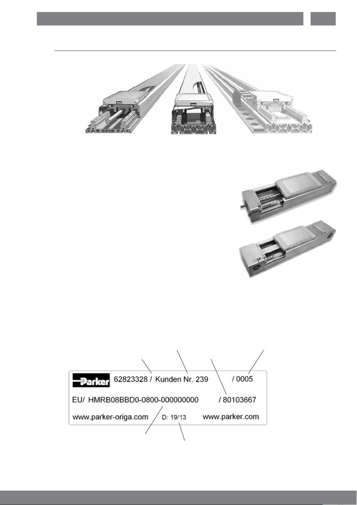
Designs
Ball screw drive Belt drive Linear motor
3.1 Scope of Application
The description in these operating instructions relates to the products.
3.1.1 Ball Screw Drive
Linear drive with ball screw drive and parallel guide
HMRS08
HMRS11
HMRS15
HMRS18
HMRS24
EN
3.1.2 Belt Drive
Linear drive with toothed belt and parallel guide
HMRB08
HMRB11
HMRB15
HMRB18
HMRB24
3.2 Type Plate
The type plate is located on the HMR end cap drive end. A second plate has been enclosed.
Customer
Customer order number
Production order
Serial order number
Product key
Calendar week of production
5

Modular Electric HMR Linear Drives
4 Application, Proper Use
The operational safety of the HMR is only ensured with proper use.
Proper use of the HMR only includes the following:
• Moving loads
• Positioning masses
• Exerting force
The HMR is driven with rotating or linear motors.
The catalog data and the conditions specied in the order conrmation must be taken into account. Please note the
limits from the technical data and the corresponding characteristic curves as per the catalog information.
The values apply to continuous operation. With intermittent operation, the combination of speed and load may
accommodate higher values for short periods. However, the individual maximum values indicated must not be
exceeded.
If the HMR is used in any other manner, this does not constitute proper use.
Obvious misuse
Any use to transport persons or applications of any manner in the private sector (consumers) is not authorized. This
may result in personal injury and damage to property. We shall accept no liability for any injury or damage resulting
herefrom. The user shall bear sole responsibility and risk.
The following are not authorized:
• Unauthorized modications to the HMR
• Processes that affect the safety of the HMR
Note all of the information attached to the HMR.
Keep this information in a fully legible condition.
In addition, note the manufacturer’s information regarding lubricants, solvents and cleaning agents.
4.1 Prerequisite for Product Usage
The installation must always be carried out such that:
• The HMR is installed without delay
• All connections and control components are accessible
• The type plate with the product name remains legible
• The ambient conditions are maintained corresponding to design delivered (IP20 or IP54)
The operator must secure any hazardous sources that may result during installation in machines and
systems between Parker-Hannin products and customer equipment, according to CE conformity.
4.2 Conversions and Modications
HMR linear drives may not be modied with respect to the design or safety-related features without the written
approval of Parker-Hannin GmbH. Any unauthorized modication in this respect will exclude any liability on the part
of Parker-Hannin GmbH.
If special attachments are to be used, the assembly regulations of the manufacturer must be observed.
The following also apply:
• Relevant accident prevention regulations
• Generally recognized safety rules
• EU directives
• Country-specic provisions.
4.3 Spare Parts and Accessories
Original spare parts and accessories authorized by the manufacturer are intended to protect your safety. The use of
other parts could change the properties of the HMR.
We shall accept no liability for any resulting consequences.
6

5 Transportation and Storage
5.1 Transportation
The electric HMR linear drives are extremely precise products. Impacts could damage the mechanical system of the
drive, resulting in a negative inuence on functionality.
To prevent damage during transportation, place the units in appropriate protective packaging.
WARNING
Lifted or suspended loads can tip over
or crash down.
This could result in severe injuries or damage to property.
► Never walk under suspended loads.
► Transport loads as close to the oor as possible.
► Securely fasten the load for transportation and note the center
of gravity.
CAUTION
Heavy parts can slip during handling!
This could result in severe injuries or damage to property.
► Hold parts or units securely.
► Wear safety gloves.
► Use tools and supports.
EN
ATTENTION
The prole may bend or snap!
► Support the drive prole appropriately during transportation and
handling (e.g. with a bar).
Transport packed or unpacked HMR units using a crane or forklift
• In storage and handling static deection of the actuator should not exceed
0.1% of total length.
• Larger deformations could result in a reduced service life, increased wear,
and increased friction. These must therefore be avoided!
• Attach ropes as shown/use fork as shown.
NOTE
Notify the shipping company and Parker-Hannin GmbH or the
delivery company immediately, in writing, of any transportation
damage or missing parts.
5.2 Storage
The storage location must be:
• Dry, free of dust and vibrations
• On a at surface.
Deection of the HMR must be avoided!
• Support the drive prole appropriately during transportation and handling.
7
Modular Electric HMR Linear Drives
6 Brief Description and Function
6.1 General
The HMR catalog contains extensive information on the following:
• Dimensions, space requirements
• Load-carrying capacity, forces and torques
• Weights and further technical data
The electric linear drives from the HMR series may only be operated within the permissible specications.
We reserve the right to make technical changes.
6.2 Setup and Mode of Action
The electric HMR linear drives are used for the linear moving and positioning of an external payload. A combination of
multiple linear drives allows the spatially oriented movements to be achieved. When the linear drive and the payload
are in motion, a force is exerted in the direction of movement.
• A payload is fastened at the pre-existing threaded holes on the carriage.
• The carriage is connected to a Drive Type (screw, toothed belt) and is moved by this Drive Type.
• The carriage is mounted on a linear guide system in a movable manner; the linear guide system is fastened to the
prole version.
• The prole version is fastened directly onto a substructure.
• The “reinforced” prole can also be used as a self-supporting structure. In doing so, attention must be paid to the
permissible loads.
• A cover can be constructed on the linear drive to reduce the penetration and discharge of dirt or abrasion.
• Lubrication can be carried out during service as needed via external lubricating nipples.
• A position signal can occur through magnetic switches mounted on the inside or outside, which are switched by a
magnetic package on the carriage.
• A displacement signal of the linearly moving carriage can be achieved by means of an installed displacement
measuring system.
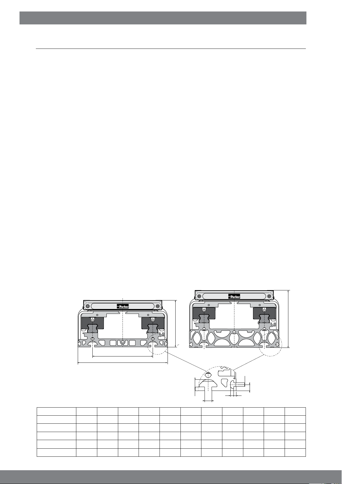
6.3 Prole versions and Carrier
A carriage is moved and force exerted through a rotational movement at the drive shaft.
• Temperature range: -20°C to +80°C
• Installation position: Any
• Humidity: Non-condensing.
Dimensions
“Basic” prole
M
K
Dimensions in mm
Dimension table – Prole versions
Series
HMRx08
HMRx11
HMRx15
HMRx18
HMRx24
K LB LR M MA MB MC N NA NB NC
85 60.0 71.0 50 5.2 4.5 2.5 4.5 3.4 3.0
110 69.5 89.5 70 5.2 4.5 2.8 4.5 3.4 3.0
150 90.0 114.0 96 6.2 6.8 3.0 6.5 5.2 4.6
180 111.5 134.5 116 8.0 7.8 4.5 8.5 5.2 4.5
240 125.0 153.0 161 10.0 10.2 5.3 8.5 5.2 4.5 3.5
LB
“Reinforced” prole
T-slot mounting
MB
MC
MA
NB
LR
NA
N
NC
2.5
2.5
3.5
3.5
8
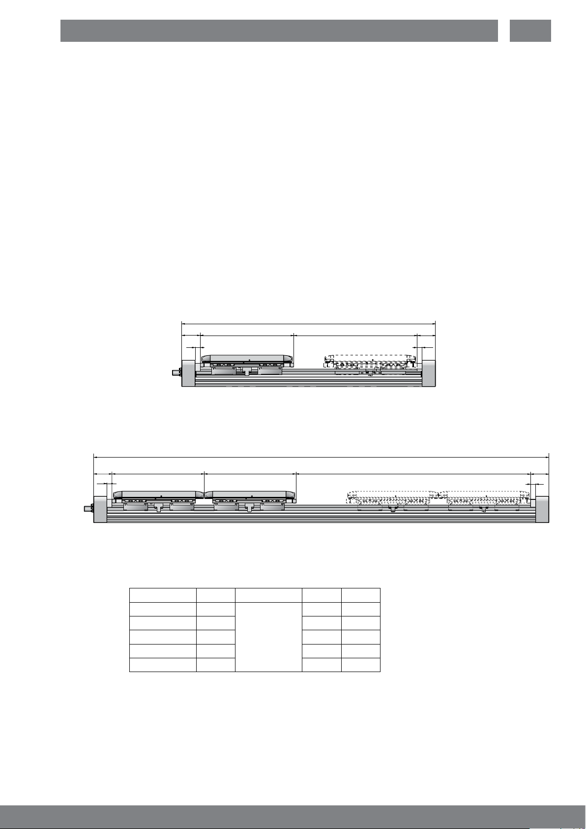
6.3.1 HMRS Ball Screw Drive
A carriage is linearly moved by a rotating ball screw drive driven by the motor; the carriage is mounted on a guide
system in a movable manner. The screw turns clockwise.
The load to be moved is fastened onto the carriage.
The permissible thrust force, speed and the linear displacement per rotation of the drive shaft depends on the
design of the screw used.
The dimensioning is as per the ordering process (HMR catalogue)
• ES = Effective Stroke
• SS = Safety Stroke
• CD
• CL
• CL
• S = Stroke
• 0S = Order Stroke
• OAL = Over All Length
Standard design with one carriage
= Carriage distance
= Carriage length Standard
S
= Carriage length long
L
X
Q
SL
CL /CL
Over All Length OAL
Stroke S = Order Stroke OS
X
Q
EN
Order Stroke OS = Effective Stroke ES + 2 x Safety Stroke SS
Over All Length OAL = Order Stroke OS + Carrier Length CL + 2 x dimension end cap X
Tandem design with two carriages
Over All Length OAL
X
Q
CL /CLSL
CL /CL
SL
Stroke S = Order Stroke OS
Order Stroke OS = Effective Stroke ES + 2 x Safety Stroke SS + Carriage distance CD
Over All Length OAL = Order Stroke OS + 2 x Carrier Length CL + 2 x dimension end cap X
Dimension table - Carriage and Over All Length HMRS
Product size CL
HMRS08
HMRS11
HMRS15
HMRS18
HMRS24
S
195
225
266
311
371
CL
L
in advance
Q X
16 54.0
20 65.0
20 62.0
20 66.0
20 73.0
Dimensions in mm
X
Q
9
Modular Electric HMR Linear Drives
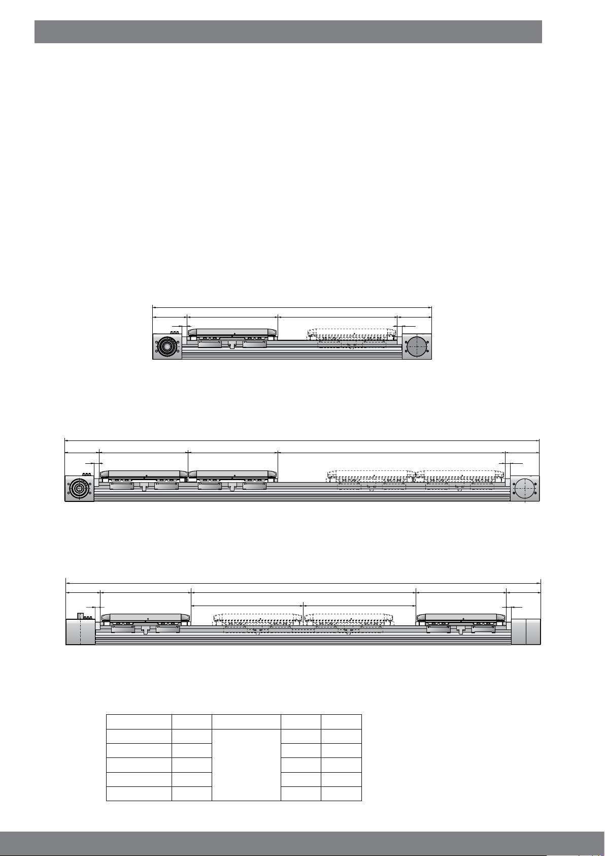
6.3.2 HMRB Belt Drive
A carriage is linearly moved by a toothed belt driven by the motor; the carriage is mounted on a guide system in a
movable manner. The load to be moved is fastened onto the carriage.
The permissible thrust force, speed and the lead constant per rotation of the drive shaft depends on the design and on
the toothed belt used.
The dimensioning is as per the ordering process (HMR catalogue)
• ES = Effective Stroke
• SS = Safety Stroke
• CD
• CL
• CL
• S = Stroke
• 0S = Order Stroke
• OAL = Over All Length
Option Carrier Standard
= Carriage distance
= Carriage length Standard
S
= Carriage length long
L
X
Q
Over All Length OAL
CL /CLSL
Stroke S = Order Stroke OS
X
Q
Order Stroke OS = Effective Stroke ES + 2 x Safety Stroke SS
Over All Length OAL = Order Stroke OS + Carrier Length CL + 2 x dimension end cap X
Option Carrier Tandem
Over All Length OAL
X
Q
SL
CL /CL
SL
CL /CL
Order Stroke OS = Effective Stroke ES + 2 x Safety Stroke SS + Carriage distance CD
Over All Length OAL = Order Stroke OS + 2 x Carrier Length CL + 2 x dimension end cap X
Option Carrier Bi-part for opposite movements
Over All Length OAL
SL CL /CLSL
X
Q
CL /CL
Stroke S Stroke S
Order Stroke OS
Order Stroke OS = 2 x Stroke S = 2 x Effective Stroke ES + 4 x Safety Stroke SS + Carriage distance CD
Over All Length OAL = Order Stroke OS + 2 x Carrier Length CL + 2 x dimension end cap X
X
Q
X
Q
Dimension table - Carrier and Over All Length HMRB
Product size
HMRB08
HMRB11
HMRB15
HMRB18
HMRB24
CL
S
195
CL
L
Q X
16 74
225 20 85
266 20 110
in advance
311 20 120
371 20 140
Dimensions in mm
10
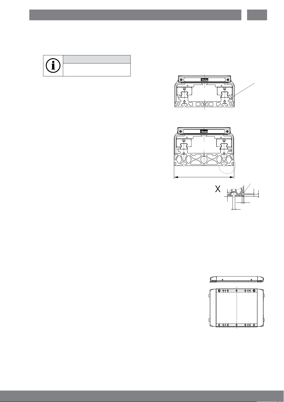
6.4 Prole versions
The user must fasten the prole version onto the corresponding substructure.
The linear drive can easily be aligned with the assistance of a reference edge machined on one side.
NOTE
The stop edge is equipped
with a groove.
Designs:
“Basic” Prole
For assembly on a continuous substructure.
“Reinforced” prole
For an extensively self-supporting substructure.
Due to the reinforced prole geometry, and the resulting
inherent stiffness, resistance to deection of twist is increased.
Basic
Reinforced
EN
T-slot for
magnetic
switch
Mounting:
T-slot
Overall width K
MB
MC
6.5 Guide System
The guide system is mounted onto the prole version. It accommodates the static and dynamic loads from the
externally moving load as well as the external forces. The permissible load data must not be exceeded.
Ball bearing guide
Runner blocks with balls are moved linearly on a precision guide rail made of steel.
The maintenance schedule recommended by Parker Hannin in section 9 must be followed.
6.6 Carriage
The carriage moves an externally connected load in a linear fashion. The external load may only be fastened at the
pre-existing threaded holes. Following versions:
Standard carriage
A carriage that is connected to the drive type (gure).
Tandem carriage
Includes a second carriage that can be freely moved on the guide system.
The external load is distributed onto two carriages that are mounted at a xed
distance, facing one another.
View “X”
Reference
edge
with groove
NC
NB
MA
NA
N
Carriage Bi-part “Bidirectional”
(only HMRB, belt, motor mounting position AP, CP, AD, CD)
With a second carriage that is driven from the belt in the opposite direction to the rst carriage.
6.7 Noise Emission
Depending on the drive types, guide system, load and speed, noise emissions of varying intensities result, which are
constrained by the setup. The operator is responsible for adhering to the applicable provisions and regulations.
11
Modular Electric HMR Linear Drives
7 Assembly
7.1 Important Information
HMR installation, and all other installations, may only be carried out by trained mechanical technicians or electricians.
The information in these instructions must be strictly observed.
Tightening torques for screws
Thread Tightening torque Tolerance
M3
M4
M5
M6
M8
M10
Remarks regarding use and operation:
1.2 Nm ± 0.2 Nm
3 Nm ± 0.5 Nm
5.5 Nm ± 0.8 Nm
10 Nm ± 1.5 Nm
20 Nm ± 3 Nm
40 Nm ± 6 Nm
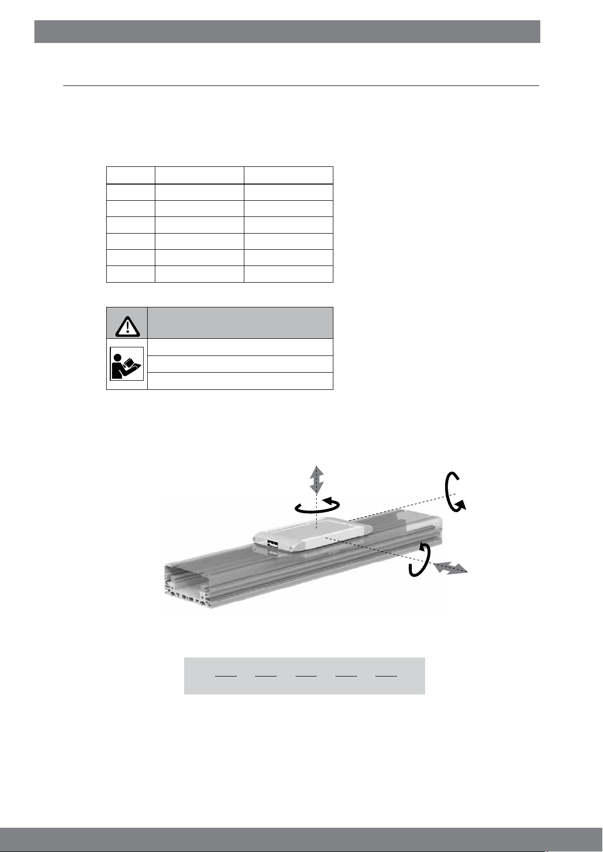
ATTENTION
Excessive forces or loads
Overload of the HMR would be possible
► Adhere to catalog data.
Mechanical
Additional drill holes or other machining may not be implemented on the HMR!
► Only attach the payload at the threaded holes on the carriage in section 7.3.
► Adhere to the permissible load limits such as weight, speed and acceleration.
► Adhere to the permissible load limits such as weight, speed and acceleration.
Fz
Mz
Mx
My
Fy
Combined loads
The maximum permissible load for linear drives subject to simultaneous multiple loads, forces and bending moments
are calculated using the formula below. Maximum permissible loads must not be exceeded.
Fy Fz Mx My Mz
L =
The sum of all loads must under no circumstance be > 1.
Take note of the additional information in the Parker HMR catalogue on the “Maximum permissible load” on page 7.
+ + + +
Fy
(max)
Fz
(max)
Mx
(max)
My
(max)
Mz
≤ 1
(max)
Electrical information
► The controller, motor, position detection and all other necessary electrical elements
must be connected according to technical rules, within the responsibility of the operator.
► Do not place magnetic switches in the vicinity of ferritic parts or moving loads.
► Only use the seating grooves and/or the mounting holes on the aluminium prole for the
assembly and mounting of the prole version, as described in detail in the HMR catalog.
12
7.2 Installation of Linear Drive
All installation measurements can be found under “6.3 Carrier prole and drive body” on page 8 and in the
HMR catalogue.
► During assembly, the HMR must be sufciently supported and securely placed in a machine/system.
ATTENTION
Straightness tolerance exceeded
The screw-on surface is important!
► Ensure evenness and straightness.
The maximum straightness and evenness in the running direction of the linear system can only be achieved if the
corresponding mounting points or surfaces are within the required tolerance.
The mounting surface for the prole version must have evenness of at least 0.2 mm/m at the clamping points.
NOTE
► Adhere to the tightening torques for screws
according to section 7.1. on page 12.
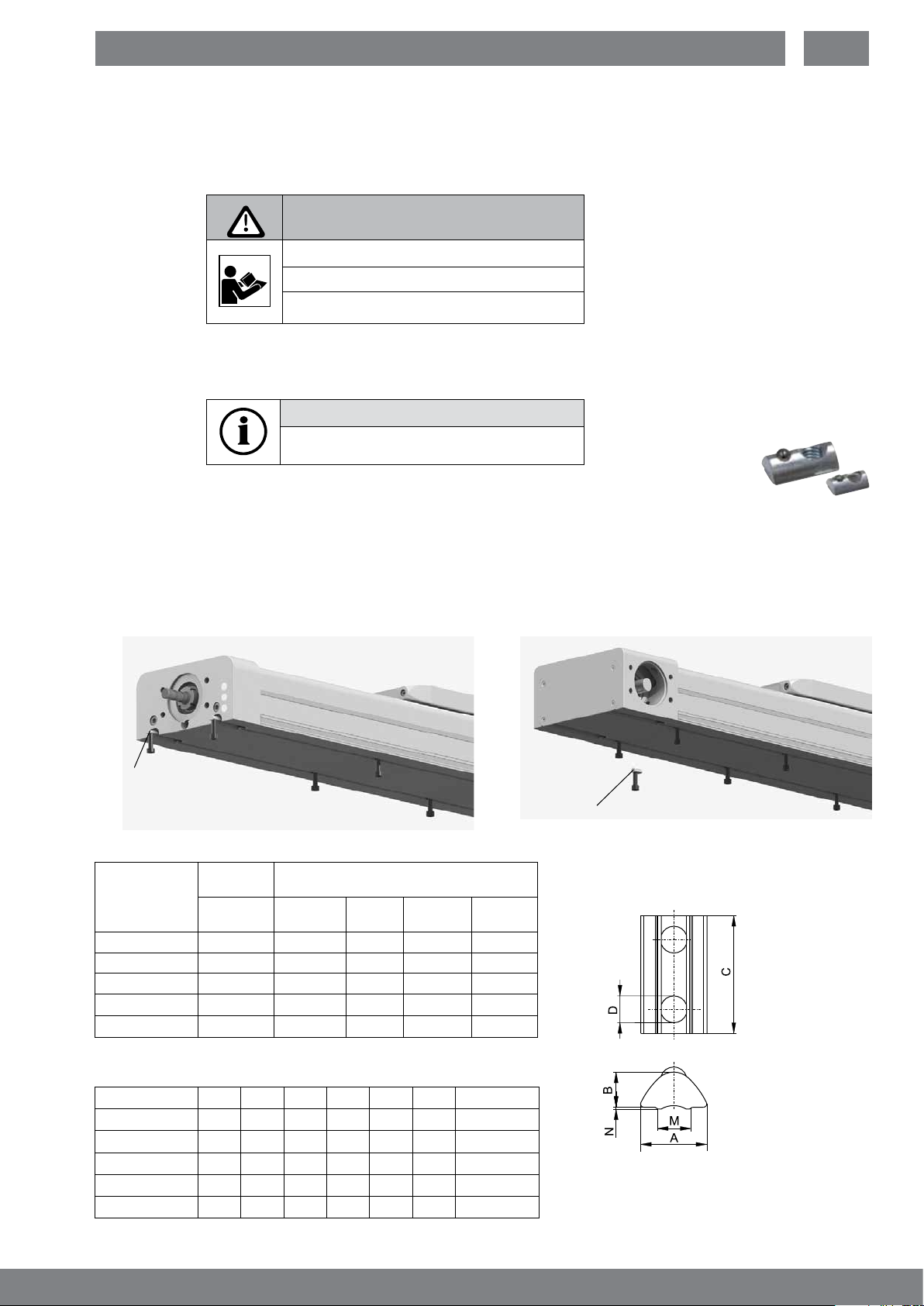
7.2.1 Mounting with T-slots
► Use of T-slot proles. Mounting from below.
.
Standard screws and sliding blocks or rails from the common prole systems can be used
Mounting parts such as sliding blocks are available as accessories.
► Please observe the required number of T-sliding blocks in accordance with the axial holding force for
secure assembly (see table below and HMR catalogue page 38).
EN
HMRS
T-slot mounting
Max, axial holding force per mounting set
T-slot
Product size
HMRx08
HMRx11
HMRx15
HMRx18
HMRx24
Dimension table
Product size
HMRx08
HMRx11
HMRx15
HMRx18
HMRx24
mounting
[N]
1,000 4 11 19 5
1,000 4 11 19 5
1,600 4 5 10 5
2,700 4 5 10 5
3,200 4 4 8 5
-
T-slot mounting
A B C Ø D M N Order no.
8.0 4.0 11.5 M5 5.0 0.5 56351FIL
8.0 4.0 11.5 M5 5.0 0.5 56351FIL
10.5 6.4 22.5 M6 6.4 0.6 56351FIL
13.5 6.7 22.5 M8 8.5 1.0 56352FIL
16.5 8.9 28.5 M10 10.5 1.0 56353FIL
horizontal horiz,
HMR
min, number of sets
required per meter
over head
side
HMRB
T-slot mounting
vertical
13
Modular Electric HMR Linear Drives
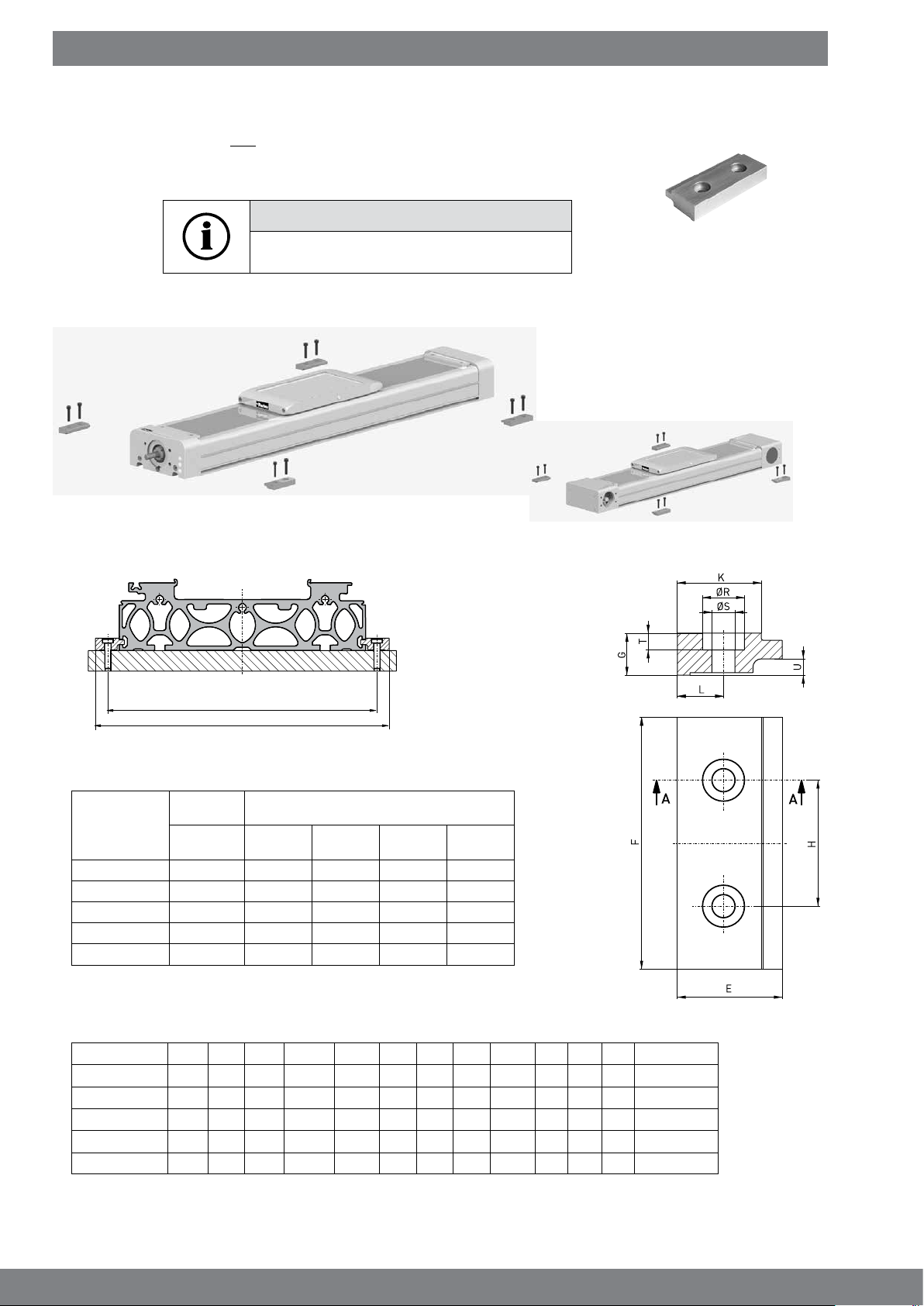
7.2.2 Mounting with T-slot xture
► Use of the side T-slot prole. Screwing direction downwards.
Clamps can be supplied as accessories, see Parker HMR catalogue from page 38.
NOTE
► Adhere to the tightening torques for screws
according to section 7.1 on page 12.
► Please observe the required number of T-sliding blocks in accordance with the axial holding force for
secure assembly (see table below and HMR catalogue page 38)
HMRS
HMRB
MP
KP
Max. axial holding force per xing pair
T-slot
Product size
HMRx08
HMRx11
HMRx15
HMRx18
HMRx24
Dimension table - T-slot xture
Product size
HMRx08
HMRx11
HMRx15
HMRx18
HMRx24
xture
[N] horizontal horiz.
800 3 6 10 4
800 3 5 9 4
1,820 3 4 6 4
2,610 3 4 5 4
2,610 3 4 5 4
E F G H K KP L MP Ø R Ø S T U Order no.
18 40 7.5 20 15 115 9 97 0.0 4.5 2.8 56363FIL
18 40 7.5 20 15 140 9 122 0.0 4.5 2.8 56363FIL
25 60 10.0 30 20 190 10 190 10.0 5.5 4.0 3.9 56355FIL
28 80 12.0 40 23 226 12 226 11.0 6.6 4.7 5.9 56356FIL
28 80 12.0 40 23 286 12 286 11.0 6.6 4.7 5.9 56356FIL
min. number of sets required per meter
side
over head vertical
14
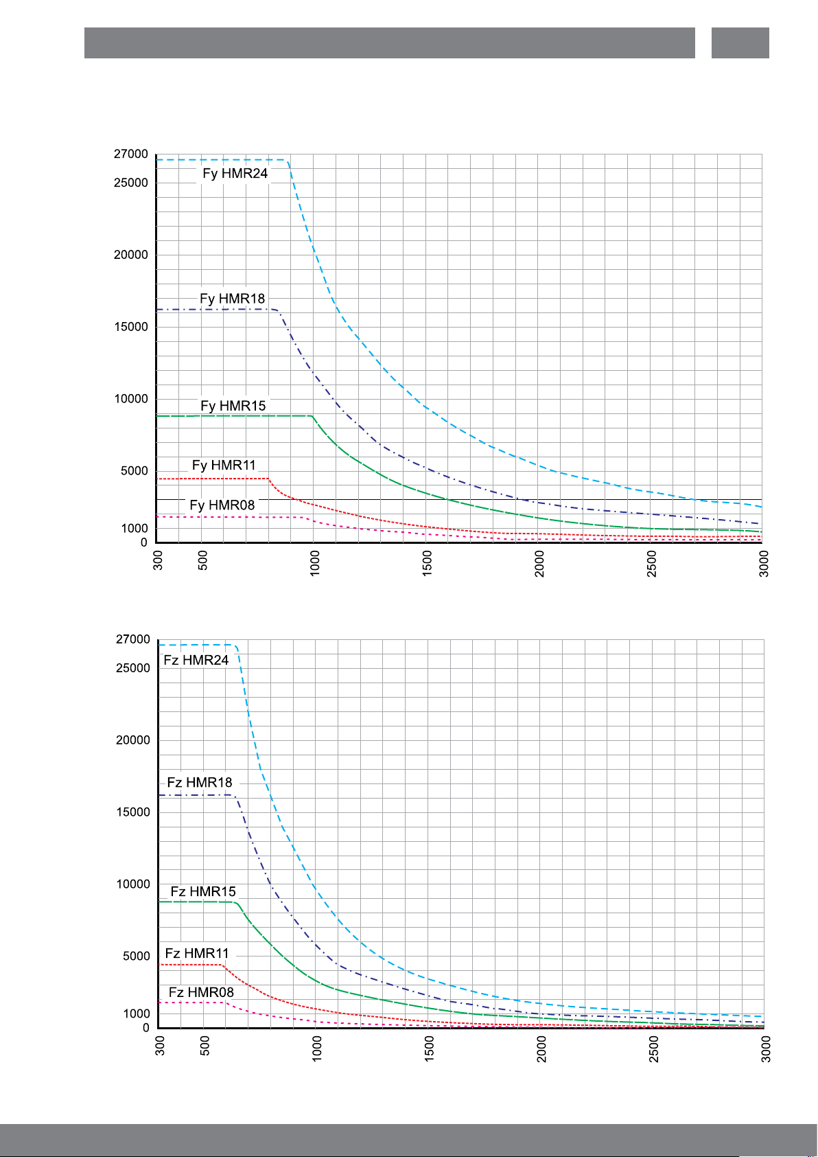
7.2.3 Distance between supports
Distance between supports FY
Force Fy [N]
EN
Force Fz [N]
permissible distance between supports [mm]
Distance between supports Fz
permissible Distance between supports [mm]
15
Modular Electric HMR Linear Drives
7.3 Attaching the Payload
The user is responsible for the use of the HMR and makes decisions on the attachment of loads as well as the
operating status with speed, acceleration and frequency of movements. The HMR may only be installed according to
the catalog’s specications.
WARNING
Danger due to fracture or deformation of components,
incorrect arrangement of loads and crashing of loads
This could result in severe injuries and damage to property.
► Attach components according to technical rules.
► Move heavy parts with a hoist; wear safety gloves.
► Observe HMR catalog data with respect to arrangement.
There are various threaded holes on the carriage available to the user of the HMR for mounting the payload.
ATTENTION
Risk of damage to the carriage
Additional holes will weaken or damage important
components and are not permitted.
► Do not drill or counter bore.
► Distribute load forces as required.
NOTE
► Adhere to the tightening torques for screws according to section 7.1 on
page 12.
The carriage has two dowel holes into which dowel sleeves can be inserted. This makes it possible to repeat the
disassembly/assembly of the payload without realignment.
Centering/alignment of payload
Suitable dowel sleeves:
(packing unit 4):
Type Item no.
HMR-08
Stop groove and centring for
the adapter sleeve are on the
same drive side
HMR-11
HMR-15
HMR-18
HMR-24
56455FIL
56455FIL
56455FIL
56457FIL
56459FIL
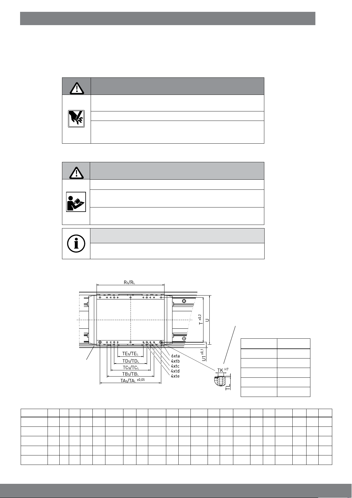
Dimension table - Carriage length Standard HMRS
Type
HMRS08
HMRS11
HMRS15
HMRS18
HMRS24
* in advance
R
SRL
128 -* 74 97 -* M4x12 70 -* M4x12 40 -* M4x12 - -* - - -* - 7 83 5,5
150 -* 96 122 -* M5x12 97 -* M5x12 65 -* M5x12 25 -* M5x12 - -* - 7 105 7,0
191 -* 120 170 -* M5x12 122 -* M5x12 - -* - 70 -* M5x12 - -* - 7 135 15,0
231 -* 150 202 -* M6x12 170 -* M5x10 122 -* M5x10 90 -* M6x12 - -* - 9 165 15,0
291 -* 192 262 -* M8x16 202 -* M6x12 170 -* M5x10 140 -* M8x16 122 -* M5x10 12 210 24,0
T TASTALta TBSTBLtb TCSTCLtc TDSTDLtd TESTELte TKH7U U1
16
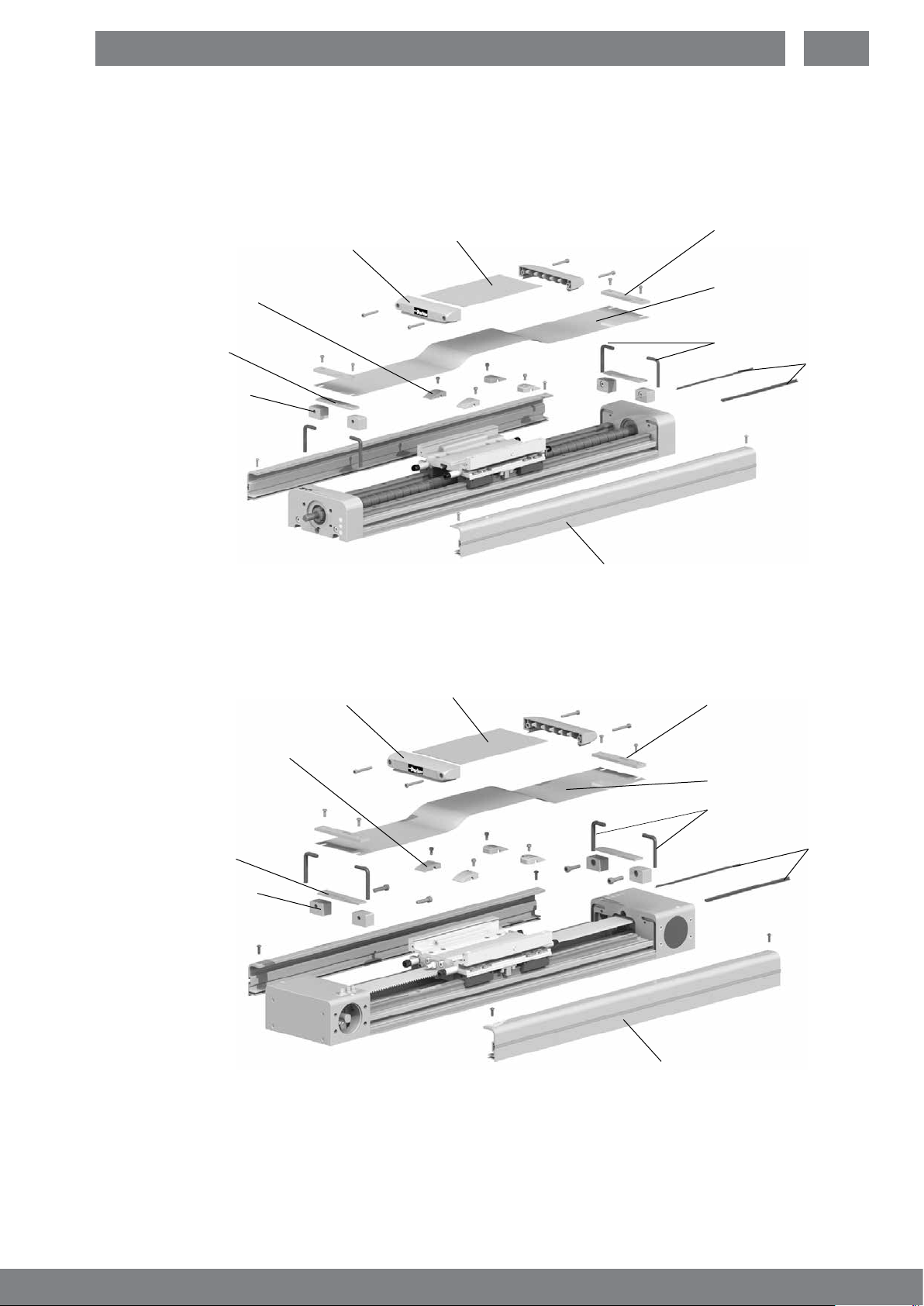
7.4 Cover for IP54
It is also possible to install various assemblies and equipment as a retrot.
When doing so, remove the cover as necessary.
HMRS
Carriage cover
Inner strip guide
Cover sheet
EN
Clamping plate
outer band
Outer band
A-coil with sealing
band
Holder cover
HMRB
Inner strip guide
Carriage cover
Cover sheet
Sealing band
Lateral
wiper
Cover
Clamping plate
outer band
Outer band
A-band coating
with sealing band
Holder cover
Sealing band
Lateral
wiper
Cover
17
 Loading...