

Page 1
S
hort Circuit Protection
Inrush
C
urrent Protectio
n
Drive Overtemperature Protectio
n
Motor Overtemperature Protectio
n
Undervoltage Protection
Overvolta
g
e Protection
C
urrent Foldbac
k
Regeneration Protection
Quick Reference
Guide
Gemini GV6 Series
Digital Servo
Controller/Drives
Protective Circuit
s
Troubleshootin
g
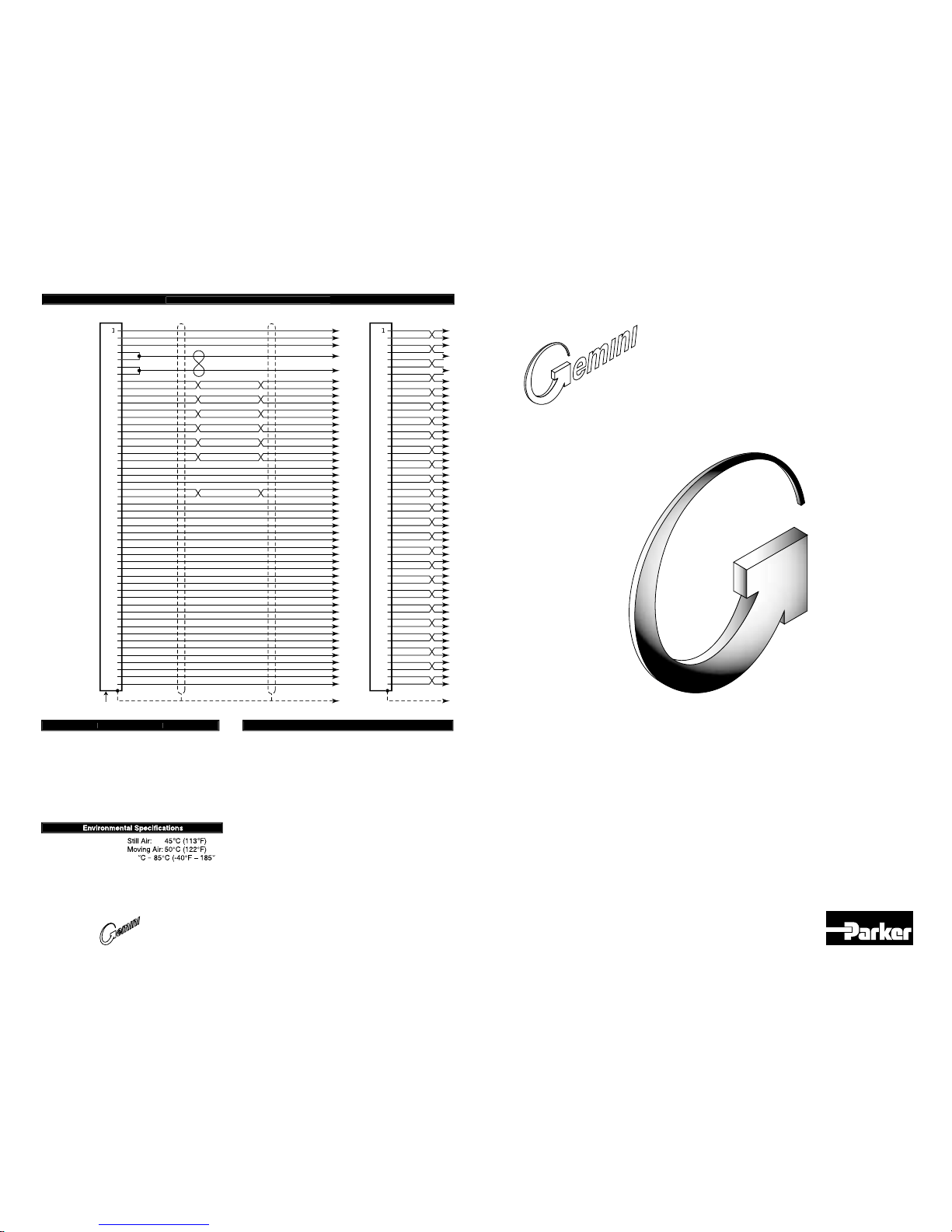
Gemini 50-Pin Connector to Flying Leads Cabl
e
Compumotor Division
Parker Hannifin Corporation
p/n 88-018365-01 B
(effective February 1, 2002)
✵
✵
✵
✵
C
ommonly used status commands (binary status bits are
numbered 1 to n, from left to ri
g
ht)
:
TERRLGError log reports the last 10 error conditions (cleared
with CERRLG
).
TAS General report, including fault conditions.
TA
S
X Additional report of conditions not covered with TAS.
T
CS
If TASX bit #7 or bit #28 is set, you can identify the
cause with TCS.
TIN
O
Bit #6 indicates status of Enable input ("1" = OK to
enable drive).
Status of digital inputs, including end-of-travel inputs.
T
OU
T Status of digital outputs.
You must configure all motor parameters. Be sure to follow the
drive configuration procedure (see Chapter 2 Installation).
Any fault condition causes the drive to shut down.
The drive can not be enabled (DRIVE1) unless the Enable input
is grounded and the Reset input is not grounded.
Use one of three methods to reset the drive (all command
settings are remembered after reset):
Issue the RESET command.
Momentarily close the Reset input.
Cycle power to the drive.
50
Pin Connecto
r
Operating Temperature
Storage Temperature: -4
0
F
)
Humidity: 0 – 95%, non-condensing
Shock: 15g, 11msec half sine
Vibration: 10 – 2000 Hz at 2g
S
hiel
d
White/Viole
t
White/Gra
y
Red/Blac
k
White/Black/Orange
White/Black/Green
Green/Black
Yellow/Red
Gray/Blue
Yellow/Green
Gray/Orange
Blue/Red
Blue/Orange
Gray
Pink
White/Pink
Orange/Black
White/Black/Blue
Yellow/Blue
Yellow/Orange
Blue/Yellow
Violet
White/Black/Red
Yellow/Black
White/Black/Yellow
Blue/Black
Green/Red
Gray/Green
Gray/White
Yellow/White
Blue/White
Gray/Brown
Yellow/Brown
Red 1
6
AW
G
Black 16 AWG
Black
White/Black
Red
White/Red
Green
White/Green
Orange
White/Orange
Blue
White/Blue
Yellow
White/Yellow
Brown
White/Brown
Black
White/Black
Red
White/Red
Green
White/Green
Orange
White/Orange
Blue
White/Blue
Yellow
White/Yellow
Brown
White/Brown
3
5
6
7
8
9
10
11
12
13
14
15
16
17
18
19
20
21
22
23
24
25
26
27
28
29
30
31
32
33
34
35
36
37
38
39
40
41
42
43
44
45
46
47
48
49
50
CE C
ABLE: 71-016943-1
0
Non-CE CABLE: 71-019861-04; -1
0
Drain & Brai
d
* 20, 30,
31 shown out of sequenc
e
Viol
et
Whit
e
R
ed
Bl
ack
R
ed
Orange
Black
Blue
Black
White
Red
White
Green
Black
Orange
White
Blue
White
Yellow
White
Green
Brown
Orange
Black
Green
White
Yellow
Brown
Brown
White
Gray
White
Brown
Orange
Yellow
Black
Blue
Brown
Violet
Brown
Violet
Black
Brown
Black
Gray
Brown
Black
Gray
Red
Brown
3
*2
0
4
5
6
7
8
9
10
11
12
13
14
15
16
17
18
19
21
22
23
24
25
*31
26
27
28
*30
29
32
33
34
35
36
37
38
39
40
41
42
43
44
45
46
47
48
49
50
Enabl
e
Digital Groun
d
R
eset
+5VDC Outpu
t
+5VDC Output
Digital Ground
Digital Ground
Step+/CW+/AX+
Step-/CW-/AX–
Dir+/CCW+/BX+
Dir-/CCW-/BX–
ZX+
ZX–
Encoder Out A+
Encoder Out A–
Encoder Out B+
Encoder Out B–
Encoder Out Z+
Encoder Out Z–
Digital Ground
Analog Output A
Analog Output B
Analog Input+
Analog Input–
Analog Ground
VINref
CNTRL-P
Input 1
Input 2
Input Ground
Input 3
Input Ground
reserved
reserved
reserved
Input Ground
reserved
reserved
reserved
Input Ground
reserved
Output Ground
Output 2
Output Ground
Output 3
Output 4
Output Ground
reserved
reserved
reserved
www.comoso.com
Page 2
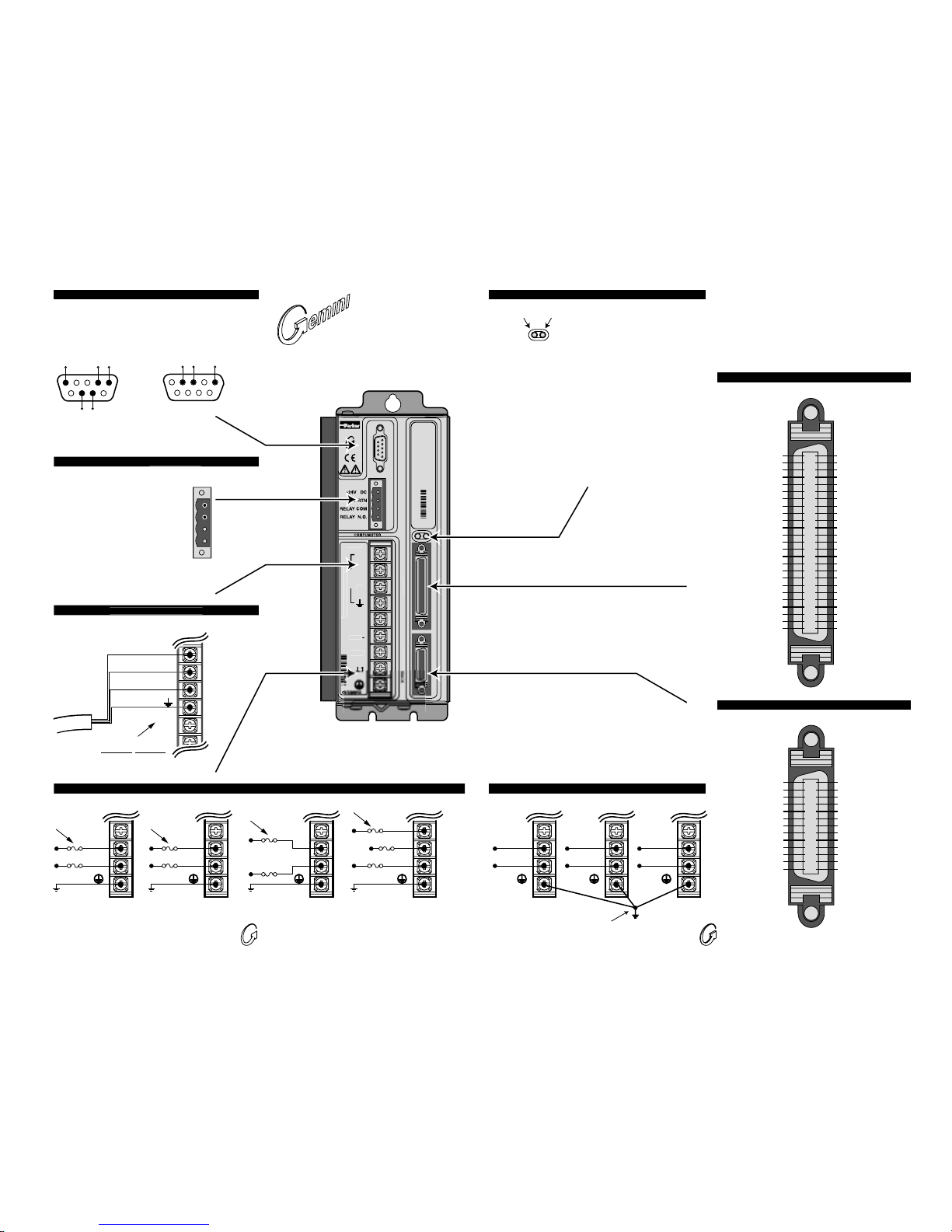
RS-232/485
DRIVE I
/O
M
O
T
O
R FEE
D
S
ERV
O
U
VBUS+
VB
US
L2
/N
T
O
R
ARNIN
G
:
GV6
Gemini
Servo
Gemini GV6
Digital Servo
Controller/Drive
✵
✵
Male
Pins
To configure all drive parameters, connect a PC or HPC to this
port. Use Motion Planner or Pocket Motion Planner for drive
configuration. (Not ASCII protocol.)
Motor Output Connection
s
AC Input Connection
s
Multiple Drive Connections
RS-232/485 Connector – Configuration Port
50 Pin DRIVEI/O Connector
26 Pin MOTOR FEEDBACK Connector
+24VDC/Relay Connecto
r
689
1
3
5
Rx Tx Gnd
RS-232 Connections
21 345
6789
Rx-
(RD A)
Tx(TD A)
GndRx+
(RD B)
Tx+
(TD B)
RS-485 Connections
+24V D
C
RELAY
COM
RELAY N.
O.
LEDs
LED Color:
Left Right Indicated State
Off Yel Initialization
Red (flash) Off Awaiting flash download
Red (flash) Yel (flash) Programming flash memory
Red Grn Keep alive mode
Grn Grn (flash) Incoming steps (variable rate)
Grn Yel/Grn (flash) Autorun mode
Red Off Drive not enabled
Drive faulted
Grn Off Drive ready
Yellow/Green
Green/Red
VAC
N or L2/N
L1
VAC
N or L2/N
L1
VAC
N or L2/N
L1
For multiple drives, use a
single point safety earth
Cos–
Cos+
Sin–
Sin+
Reserved
Reserved
Ref 1–
Ref 1+
Hall C
Hall B
Hall A
Hall Ground
Hall +5V
Thermal Switch
Thermal Switch
Digital Ground
Encoder Z–
Encoder Z+
Encoder B–
Encoder B+
Encoder A–
Encoder A+
Encoder Ground
Encoder Ground
Encoder +5V
Encoder +5V
13
12
11
10
9
8
7
6
5
4
3
2
1
26
25
24
23
22
21
20
19
18
17
16
15
14
Output Ground
Output 6
Output 5
Output Ground
Output 4
Output 3
Output Ground
Output 2
Output Ground
Output 1
Input Ground
Input 8
Input 7
Input 6
Input Ground
Input 5
Input 4
CNTRL-P: 4 – 8
Input Ground
Input 3
Input Ground
Input 2
Input 1
CNTRL-P: 1 – 3
VINref
Analog Ground
Analog Input–
Analog Input+
Analog Output B
Analog Output A
Digital Ground
Encoder Out Z–
Encoder Out Z+
Encoder Out B–
Encoder Out B+
Encoder Out A–
Encoder Out A+
Reserved
Reserved
Reserved
Reserved
Reserved
Reserved
Digital Ground
Digital Ground
+5VDC Output
+5VDC Output
Reset
Digital Ground
Enable
25
24
23
22
21
20
19
18
17
16
15
14
13
12
11
10
9
8
7
6
5
4
3
2
1
25
24
23
22
21
20
19
18
17
16
15
14
13
12
11
10
9
8
7
6
5
4
3
2
1
50
49
48
47
46
45
44
43
42
41
40
39
38
37
36
35
34
33
32
31
30
29
28
27
26
U
V
W
Motor Cable
DRIVECompumotor Cable
Color Code:
Black #1
Black #2
Black #3
Grn/Yel
GV6-L3n
at 120VAC
95 – 132VAC
GV6-U3n/6n/12n
at 120/240VAC
VBUS–
L2/N
L1
95 – 264VAC
Fuses
N/C
N
L1
Fuses
GV6-H20n at 208/
240VAC 1-phase
165 – 264VAC,
1-phase
Fuses
L3
L2
L1
GV6-H20n/H40n at
208/240VAC 3-phase
165VAC –
264VAC
3-phase
L3
L2
L1
Fuses
User supplies +24VDC for
"keep alive" power to drive:
19.2 – 28.8 VDC
500 mA minimum
When drive is enabled, it
holds relay closed.
Relay rating: 5A at 24VDC or
120VAC.
If drive is faulted or disabled,
relay will open. (Typical use:
control of motor brake.)
GV6-L3
GV6-U3/6/12
GV6-H20
#8 (M4)
spade fork,
0.325"
max. width
Drive terminals:
Mating terminals:
GV6-H40:
#10 (M5)
ring terminal,
0.25" I.D., 0.50" O.D.
maximum width
www.comoso.com
 Loading...