

Page 1
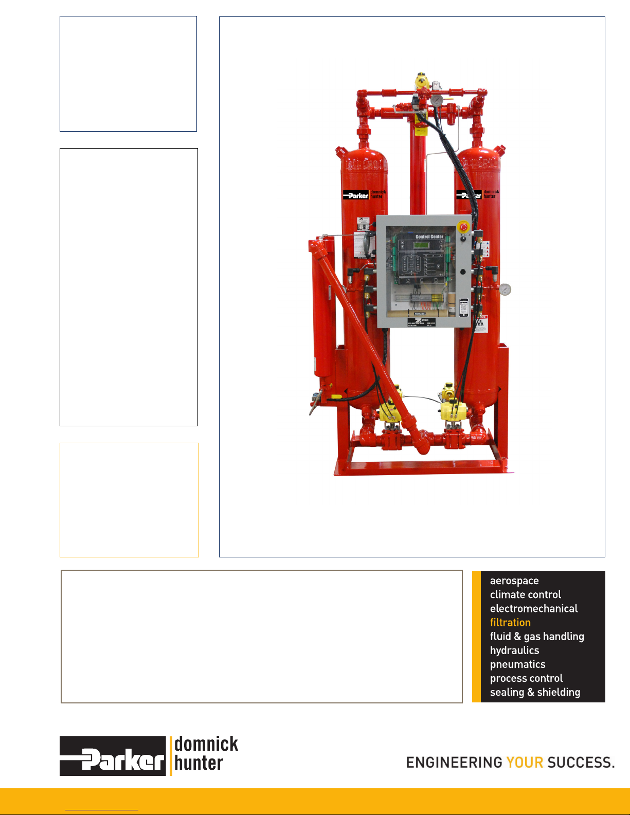
Heatless High Pressure
Desiccant Dryers
Models DTX10 -DTX80
User Guide
Page 2

DTX10 - DTX80 USER GUIDE
Introduction Letter
Dear Customer,
Let us take this opportunity to introduce our company.
Parker is an innovative manufacturer of industrial equipment for compressed air
systems.
Our product line includes natural gas dryers, fluid coolers, water separators, air filters,
refrigerated air dryers, and heatless and heat reactivated desiccant air dryers. Our
products can be found in all corners of the world.
No effort has been spared to provide a comprehensive instruction manual for the use
of the Parker Dryer. Information is given not only for the user, but also for the technical
personnel who may repair the dryer in the event that this is ever necessary. It is
recommended that all who will have responsibility for the dryer carefully read all sections
of this manual before commencing with the installation.
The most important step is for you as a customer is to call us first at
1-855-5TRYFAF if you are experiencing a problem with your dryer.
If there is a question regarding this manual or our warranty policies and procedures,
please call. We would be happy to speak with you.
Thank you for choosing Parker products.
Parker Service Department
2
Page 3

DTX10 - DTX80 USER GUIDE
Contents
1. Inspection and Installation 4
1.1 Inspection 4
1.2 Dryer Location 4
1.3 Installation 4
2. Safety and System Precautions 6
3. General Operation 6
4. Sequence of Operation 8
5. Start Up 9
6. Operational Notes 10
6.1 Variable Cycle Control 10
7. Shutdown Procedures 11
8. Demand Cycles 12
8.1 CycleLoc 12
8.2 Dryers Equipped with DDS 12
9. Maintenance Program 14
9.1 Desiccant Replacement 14
9.2 Inlet and Exhaust Valve Repair 15
10. Parts (general parts description) 16
11. Troubleshooting Guide 17
12. High Humidity 19
12.1 Principle of Operation 19
12.2 System Components 19
12.3 Calibration Procedure 19
12.4 Precautions, Limitations, and Hazards 19
13. Optional DDS 20
13.1 Quick-Start for Dryers Equipped with DDS 20
13.2 Design and Theory of Operation 20
13.3 Mounting the Probe 21
13.4 Probe to Analyzer Connection 21
13.5 Electrical Connection 21
13.6 Troubleshooting 21
13.7 DDS Display: 22
14. Optional Pre/After Filters 23
15. Warranty 25
Appendix - Spare Parts 27
Appendix - Drawings 28
3
Page 4

DTX10 - DTX80 USER GUIDE
1. Inspection and Installation
PRIOR TO INSTALLATION OR START-UP OF DRYER, THIS ENTIRE MANUAL SHOULD BE READ
AND UNDERSTOOD.
1.1 Inspection
All Dryers are tested and inspected at the factory prior to shipping. Inspect the dryer carefully upon
arrival and note any damage on the freight bill. Uncrate and inspect for concealed damage. File
claims with the carrier immediately and notify the manufacturer service department.
1.2 Dryer Location
Locate the dryer in an area accessible for maintenance. The dryer should have minimum 36”
clearance on all sides. See dimensional print for specic clearance requirements. The area should be
clean, well lighted and have a level, vibration free oor. For standard applications, ambient temperatures
should range between 35°F and 100°F. Consult the factory concerning applications outside this
temperature range.
1.3 Installation
(See typical installation drawing)
NOTE: All piping and electrical connections should be checked to insure they have maintained their
integrity during shipping and installation.
WARNING! Incorrect installation may void warranty! IMPORTANT! Sizes above 1500 SCFM require eld
desiccant charging. Units above 1500 are shipped empty due to weight constraints.
- Coalescing Pre-Filter with auto drain must be installed.
- Standard dryers are designed for 100°F inlet temperature or less.
- Ambient temperatures should be between 35°F and 100ºF.
- Dryer should be located in an area accessible for maintenance.
- Location should be clean, cool, with a level, vibration free oor.
- Location of receiver may vary depending on particular conditions and type of compressor.
- Auto drains are required when receiver is mounted up- stream of dryer.
Make the following connections:
1. Inlet piping, including an isolation valve.
2. Outlet piping, including an isolation valve.
3. Coalescing Pre-Filter and Particulate After-lter.
IMPORTANT! Desiccant dryers are designed to remove water VAPOR only!
Locate the coalescing lter as close to the dryer as possible. The air to be dried must pass through a
Coalescing Pre-Filter for removal of entrained condensate and oil to prevent fouling of the desiccant.
Liquid condensate entering the bed will lead to overloading of the dryer, poor dew point performance,
and rapid deterioration of the desiccant. Oil entering the desiccant bed may permanently reduce the
capacity of the desiccant.
A Particulate After-lter should be provided to prevent desiccant dust from traveling down stream.
Desiccant dust may cause contamination and excessive wear to equipment. Differential pressure
indicators should be installed on lters for monitoring of elements. A particulate lter before the dryer
and adsorber after the dryer are optional.
4. Auto Drain on Pre-Filter. An Automatic Drain is required on the Pre-Filter and all other upstream
collection points to remove condensate.
5. IMPORTANT! Bypass piping is necessary. A bubble tight valve should be used for bypass
around lters and dryer for servicing.
4
Page 5
DTX10 - DTX80 USER GUIDE
6. Make required electrical connections to control box. Refer to applicable drawings.
NOTE: Customer to provide short circuit protection for dryer.
7. Access ports should be provided upstream and downstream of the dryer for dew point,
pressure, and temperature checks. Periodic checking of the dew point just downstream
of the dryer is the best indication of whether the dryer is performing as expected. A High
Humidity Alarm or DDS are available as options.
8. All piping should be adequately supported and at least of equal size to the dryer connections.
9. To reduce maintenance and increase dryer efciency, the exhaust ports can be piped to
a location where the exhaust mufers are not required. The piping MUST NOT create
any back pressure on the regenerating tower and must be up-sized accordingly. It is
recommended that the exhausts be piped separately for ease of troubleshooting
and maintenance.
Before any attempt is made to operate the dryer, the operator should thoroughly read and
understand this instruction manual. Improper operation will cause poor results from
the dryer.
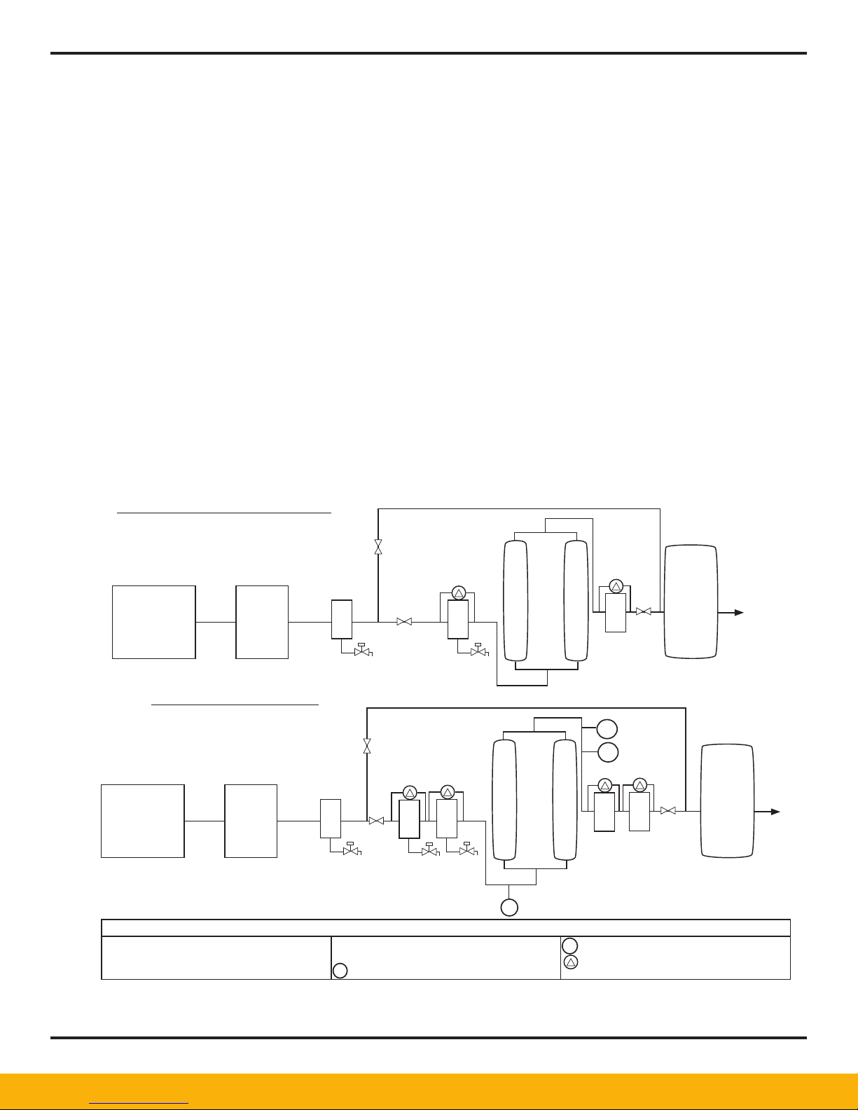
RECOMMENDED INSTALLATION
CLEAN DRY, CONTAMINANT FREE AIR
MINIMUM REQUIREMENTS
BY-PASS VALVE MUST BE BUBBLE TIGHT
ROTARY
OR CENTRIFUGAL
COMPRESSOR
AFTER-
COOLER
IDEAL INSTALLATION
BY-PASS VALVE MUST BE BUBBLE TIGHT
ROTARY
OR CENTRIFUGAL
COMPRESSOR
AD = AUTOMATIC DRAIN
F = PARTICULATE FILTER
AFTER-
COOLER
SEPARATOR
AD AD
BY-PASS PIPING (OPTIONAL)
SEPARATOR
FILTERS
F
AD AD
C = COALESCING FILTER
A = ADSORBING FILTER
= TEMPERATURE INDICATOR
T
BY-PASS PIPING
COALESCING
Pre-lter
C
C
AD
KEY
T
DRYER
AIR
DRYER
PARTICULATE
FILTER
AIR
AIR
RECEIVER
F
D
T
FILTERS
A
F
= DEWPOINT INDICATOR/CONTROLLER
D
= DIFFERENTIAL PRESSURE INDICATOR
RECEIVER
AIR
5
Page 6

DTX10 - DTX80 USER GUIDE
2. Safety and System Precautions
• Use EXTREME CAUTION when working in the vicinity of the dryer.
• Relieve pressure before servicing dryer or associated equipment.
• Disconnect power before servicing dryer.
• Use ear and eye protection when in the vicinity of the dryer or exhaust ports, especially if the dryer is
being operated without mufers. Even when mufers are used, a tower blowing down to atmosphere
will raise particles, create more noise than during “normal” operation and may startle an individual not
used to this portion of the operation.
• In the case of an overpressure situation there is a safety relief valve on each tower designed to protect
the equipment. If these end up pointed in a hazardous direction after dryer installation, they should be
piped to safe location.
• Automatic or manual drain valves will eject water, oil, particulates and air under partial pressure when
operated. proper precautions must be taken.
• Condensate drainage from compressed air systems may contain oil or other contaminants. Follow all
applicable regulations for safe handling and disposal.
• Various component failures could cause large air loss and subsequent pressure drop. Preventive
maintenance should be performed to reduce the likelihood of this. If this occurs, bypass the dryer
immediately to restore ow and pressure.
• Activated Alumina dust is considered a nuisance dust. Proper precautions should be taken when
handling desiccant. For more information and for other types of desiccant, refer to applicable
Material Safety Data Sheet. For disposal of used desiccant refer to the applicable regulations.
NOTE: Desiccant contaminated with oil or other foreign substances may be covered under disposal
regulations for the contaminant.
3. General Operation
Desiccant dryers work on the principle of adsorption. Adsorption is the process of removing water VAPOR
from the air to be dried. All condensed liquid water should be removed from the inlet air stream prior to
reaching the dryer by suitable separators, traps, lters, and drains. The dryer can not be burdened with
liquid condensate carry-over.
All desiccants are adversely affected by oil, aerosols, dirt, rust, scale or liquid water. Effective pre-ltration
in conjunction with automatic condensate drainage is a must for proper dew point suppression and long
desiccant life.
The saturated inlet air is alternately cycled through each of the two desiccant beds. One bed is “on-line” at
full line pressure and ow, adsorbing water vapor from the saturated inlet air. This is the drying bed.
The other bed is “off-line” at atmospheric pressure (0 PSIG) being regenerated by a depressurized portion
of the dried outlet air (purge air). This is the regenerating bed.
The quantity of purge air for a standard pressure dryer is approximately 5% of inlet design ow. This air is
taken from the dry air outlet, directed through the purge ow controls, purge check valves, desiccant bed,
and nally exhausted to atmosphere to accomplish regeneration. Purge air consumption is typically the
largest cost involved with operating a heatless desiccant air dryer. (Purge air is “non-recoverable” and the
air system in question must be designed to allow for this usage.)
IMPORTANT! The dryer is designed to remove only water vapor. You might see a small amount of
condensate forming at the exhaust due to the Joule-Thomson cooling effect created by the
depressurizing air.
6
Page 7
DTX10 - DTX80 USER GUIDE
Prior to switching a freshly regenerated bed “on-line” to become the drying bed, it must be slowly
pressurized from atmospheric pressure to line pressure. This step is called repressurization.
Repressurization prevents bed uidization (lifting) and associated dusting.
Following repressurization, the beds switch functions with the fresh bed now drying and the saturated bed
being regenerated.
Note that one bed is always “on-line” drying. Also note that purge air is always being consumed except
during repressurization.
This cycle will continue automatically unless the dryer is shut down, operated in the CycleLoc mode or
equipped with a DDS.
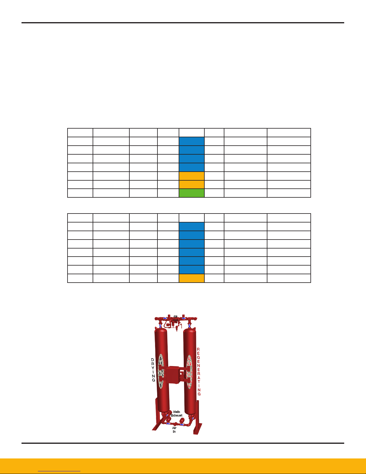
MODEL CAPACITY PSI CFM COLOR SIZE DES/TOWER IN/OUT CON.
DTX 10 50 no gauge 2.5 BLUE 3/32" 12 3/8" NPT
DTX 20 95 no gauge 5 BLUE 3/32" 15 1/2" NPT
DTX 30 200 110 10 BLUE 3/32" 37 3/4" NPT
DTX 40 350 225 18 BLUE 3/32" 75 1" NPT
DTX 50 550 185 28 GOLD 1/8" 120 1 1/2" NPT
DTX 60 800 275 40 GOLD 1/8" 150 1 1/2" NPT
DTX 80 1400 200 70 GREEN 3/16" 300 2" NPT
High Pressure 500 MAWP Technical Specs
High Pressure 1000 MAWP Technical Specs
MODEL CAPACITY PSI CFM COLOR SIZE DES/TOWER IN/OUT CON.
DTX 10 75 - 2.3 BLUE 3/32" 12 3/8" NPT
DTX 20 130 - 4 BLUE 3/32" 15 1/2" NPT
DTX 30 250 90 8 BLUE 3/32" 37 3/4" NPT
DTX 40 400 135 12 BLUE 3/32" 75 1" NPT
DTX 50 750 275 23 BLUE 3/32" 120 1 1/2" NPT
DTX 60 1000 375 30 BLUE 3/32" 150 1 1/2" NPT
DTX 80 1800 375 54 GOLD 1/8” 300 2" NPT
Dryer Outlet Flow
Dryer outlet ow is equal to the dryer inlet ow minus the purge ow.
Air
Out
Main
Exhaust
Air
In
DTX Series Flow Schematic
7
Page 8

DTX10 - DTX80 USER GUIDE
4. Sequence of Operation
The sequence is controlled by a Solid State Timing and Relay circuit (Sequence Annunciator) which in turn
controls ve electric solenoid valves. The rst four are 3-Way Normally Closed Valves, which supply control
air to operate air operated switching inlet and exhaust valves. The Inlet Valves are Normally Open and are
closed by supplying dry control air to the valve actuator. The Exhaust Valves are Normally Closed and are
closed by supplying dry control air to the valve actuator. The fth solenoid is the repressurization valve.
There are also four mechanical check valves, two outlet and two purge, that allow for proper air ow.
STEP 1- LEFT DRYING; RIGHT REGENERATING
SOLENOID #1 is de-energized sending no air to Exhaust Valve #1 (left side). Exhaust Valve #1 is closed.
SOLENOID #2 is de-energized sending no air to Inlet Valve
#1 (left side). Inlet Valve #1 is open. All of the wet inlet air is owing through Inlet Valve #1. It is dried as it
passes through the left tower desiccant bed and exits out the left side Outlet Check Valve to the dryer outlet. The left tower is the Drying tower and the associated pressure gauge should read line pressure,.
At the same time SOLENOID #3 is energized sending a signal to Inlet Valve #2 (right side). Inlet Valve #2 is
closed, preventing inlet air ow through the right tower.
SOLENOID #4 is energized sending a signal to Exhaust Valve #2 (right side). Exhaust Valve #2 is open.
(NOTE: When exhaust valve rst opens, the associated tower will depressurize from line pressure to atmospheric pressure.) Purge air will now ow from the dry air outlet through the Purge Adjusting valve, Purge
Orice and the right hand Purge Check Valve. This purge air then proceeds through the right tower near
atmospheric pressure, removing the moisture and exiting the right hand Exhaust Valve and Mufer in vapor
form (at no time should the dryer expel any signicant amount of liquid water from the mufer; this is a sure
sign of trouble in the system). The right tower is the regenerating tower, the associated pressure gauge
should read “0” PSIG.
SOLENOID #5 is de-energized and closed.
STEP 2 - LEFT DRYING, RIGHT REPRESSURIZING
While the left tower is still drying, Solenoid #4 will de- energize, relieving the control air signal on the right
exhaust valve, returning that valve to its normally closed state. Closing this valve keeps air in the tower, allowing the depressurized part of the dryer to build up pressure or “repressurize”. At the same time Solenoid
#5 is energized and opened, providing additional air to the tank coming from the purge line to ensure full
repressurization of the dryer. Prior to switching towers, all of the gauges should equalize to line pressure.
STEP 3 - LEFT REGENERATING, RIGHT DRYING
Step 3 is the reverse of step 1. Solenoid #1 is energized, providing control air to and opening the left exhaust valve.
Solenoid #2 is energized, providing control air to and closing the left inlet valve. Solenoid #3 and #4 are
de-energized. Thus the right inlet is open, and the right exhaust is closed. All the wet air is now owing
through the right tower and is being dried at line pressure. The left tower is being regenerated at
atmospheric pressure. Solenoid #5 is de- energized and closed.
STEP 4 - LEFT REPRESSURIZING, RIGHT DRYING
Step 4 is the reverse of Step 2. Solenoid #1 de-energizes, allowing the left exhaust valve to close and allowing the dryer to repressurize. In addition, Solenoid #5 energizes providing additional air for repressurization.
NOTE: The Purge Gauge (middle) should read purge pressure, except during repressurization. Purge pressure for standard inlet design conditions is listed on page 4. For other than standard or design conditions
consult the factory.
8
Page 9
DTX10 - DTX80 USER GUIDE
5. Start Up
Please read and understand the entire manual before operating the dryer.
Check and read over wiring diagrams that pertain to your unit and make sure the correct power supply is connected,
but do not energize circuit at this time. Provide proper short circuit protection. Follow all applicable codes.
If you do NOT want the dryer to cycle automatically when energized, close the control air isolation valve. If the
system has already been pressurized, bleed off the control air pressure by opening the knob on the bottom of the
control air lter and reclosing.
Before starting the dryer your compressor should be running, your air system pressurized and the dryer bypassed
and not yet pressurized.
SLOWLY open the inlet isolation valve admitting compressed air to the dryer. It is important to pressurize the dryer
slowly to prevent uidization of the desiccant bed. The dryer outlet isolation valve should be closed at this time.
SLOWLY open dryer outlet isolation valve. At this point all valves are in “normal” positions; air is owing through
both towers and downstream.
Close the dryer bypass valve. Bypass valves must be bubble tight to prevent moisture from migrating around the
dryer and contaminating the dry air outlet.
It is required that the dryer be started without the mufers installed. This will expedite removal of excess desiccant
dust and prevent premature clogging of the exhaust mufers.
CAUTION: USE EAR AND EYE PROTECTION WHEN OPERATING DRYER WITHOUT MUFFLERS. EXCESSIVE
NOISE WILL BE CREATED. DUST AND PARTICLES FROM THE SURROUNDING AREA MAY BECOME
AIRBORNE. OPERATION WITHOUT MUFFLERS EXCEEDS OSHA LIMITS.
Check the Variable Cycle Control setting. It should normally be set at the standard 10 minute, 100% load.
Energize the electrical circuit. If the control air valve is open the dryer will begin to cycle.
If the control air valve is closed, open it to begin the dryer cycle. At this point one tower will exhaust its air to
atmosphere. See “CAUTION” statement above.
Check and adjust the setting of the purge pressure indicator or purge ow meter in accordance with the
specications for your dryer. Normally, purge ow is approximately 15% of design ow for the dryer. Note that even
if you are operating under a light load the purge can not be reduced if you are operating in the DDS or CycleLoc
modes, or a xed timed cycle other than the standard 10 minute, 100% load cycle.
9
Page 10

DTX10 - DTX80 USER GUIDE
6. Operational Notes
Never service the dryer or lters without rst relieving pressure.
Check all air connections for leaks and tighten as required. Downstream air leaks will affect dew point.
Bypass air leaks will affect dew point. Only soft seat bypass valves may be used.
Dryer will not perform without proper pre-ltration, condensate drainage, and purge ow. Dryers may
require up to 48 hours of operation to reach normal operating dew points. Therefore, indicators and/or
alarms should not be recognized until that time. Applications requiring dew points lower than -40°F, or with
nonstandard operating conditions, may require additional time to reach equilibrium.
Exhaust valves and/or exhaust mufers may have to be cleaned due to dusting in shipping and start-up.
A desiccant dryer should never be suddenly pressurized or depressurized. This will cause uidizing and
dusting of the desiccant bed.
After start-up, some dusting may occur. This will diminish with time. Some dusting may occur with normal
operation. The Exhaust Mufers should be cleaned regularly and an After-lter should be used.
Flow direction is Upow Drying - Downow Purge. Switching Failure Alarm is optional and the dryer must
be operating over 70 PSI for proper function of the alarm. Dryer valving is “fail-safe” on power loss. This
means the inlet valves open and exhaust valves close, allowing system to remain pressurized and air to
ow through both towers, and down stream.
The standard dryer has been designed for drying service to 500 PSIG.
The dryer must repressurize before switching.
6.1 Variable Cycle Control
The heatless dryer is equipped with Variable Cycle Control. This control allows for easy adjustment
to meet varying plant loading. By using this control, the dryer can be set to one of two standard
xed time cycles, a) standard 100% load (10 minute), b) short cycle -80°F dew point (5 minute).
Complete cycle times are given below.
Cycle Times (time in minutes: seconds)
The short cycle will provide a -40°F to - 80°F dew point when operating at or below design
conditions. Always set the purge as if you had a full inlet ow when using these cycles. The cycles
automatically compensate for the light loading; there is no need to turn the purge down.
TOTAL
CYCLE DRYING REGEN. REPRESS.
100% Load 10:00 5:00 4:15 0:45
75% Load 15:00 7:30 4:15 3:15
50% Load 20:00 10:00 4:15 5:45
Short (-80) 5:00 2:00 2:00 0:30
TIME
PER TOWER TIME
10
Page 11

DTX10 - DTX80 USER GUIDE
7. Shutdown Procedures
Isolation
1. Allow dryer to reach repressurization step and fully repressurize
2. While fully repressurized, remove power from the dryer by turning off disconnect.
3. Open bypass pipe.
4. Close outlet isolation valve.
5. Close inlet isolation valve.
Depressurization
1. Open bypass piping.
2. Close outlet isolation valve.
3. Close inlet isolation.
4. Allow dryer to run. The normal cycle will allow both tanks to blow down and depressurize.
5. Disconnect power.
6. With the “Basic Filter Package” dryers, open manual ball valves on lters to allow full
depressurization. Leave ball valves on lters open while servicing. Without the “Basic Filter
Package”, close control air lter off. Remove nylon tubing from control air lter or any control
solenoid. Reopen control air lter to fully depressurize. Leave control tubing off while servicing.
To restart, follow “Start-Up” procedure. IMPORTANT! Always remove all pressure and disconnect
all power before servicing the dryer.
IMPORTANT! If DDS is installed and the dryer will be out of service for an extended period of time,
remove the probe and store in a safe, dry location. The probe will be damaged if exposed to prolonged
periods of saturated conditions.
11
Page 12

DTX10 - DTX80 USER GUIDE
8. Demand Cycles
CycleLoc and DDS are demand cycles available for any heatless dryer. CycleLoc is standard on all heatless
dryers. DDS is an option that needs to be purchased. These cycles offer improved operating efciency over
xed time cycles for applications requiring a -40°F dew point and that will see lighter than design moisture
loading. Demand cycles reduce total purge consumption and thus reduce energy usage by tailoring the
cycle to actual loading, vs., xed cycles which assume 100% design loading. Demand cycles can not
accommodate for heavier than design loading. It can not shorten the xed cycle, only lengthen it.
8.1 CycleLoc
The CycleLoc feature is built in to every model. It can be used to interface the dryer with the
compressor. The dryer must be able to handle at least full ow of the compressor and the receiver
should ideally be located downstream of the dryer. A dry (unpowered) contact closure across
the CycleLoc terminals on the Sequence Annunciator will cause the dryer to immediately pause
its cycle & stop purging. The contact closure needs to correlate with the compressor stopped
or unloaded. When the contact opens the dryer cycle will resume where it left off. Typically a
contact on the compressor pressure control is utilized. If a dry normally open (with compressor
running) contact is not available, an auxiliary relay will need to be added. The jumper JP1 must be
installed for correct CycleLoc operation. Please consult the factory for more information.
8.2 Dryers Equipped with DDS
The DDS is a digital display. The sensor is a thin lm gold aluminum oxide design. The DDS
observes the outlet pressure dew point of the dryer and digitally displays it. The DDS feature
tailors the dryer cycle to actual loading conditions, minimizing energy usage. Without the Dew
Point Monitor, the cycle is xed and “worst case” design conditions are assumed.
The Demand Cycle is accomplished by providing a discrete dry contact closure across the
CycleLoc terminals on the Sequence Annunciator. The Variable Cycle Control Switch must be set
to 100% load setting for the DDS to work. If the dryer is maintaining a good dew point AFTER
the rst ve minutes of drying, the DDS will override the xed cycle and keep the current tower
“on-line” until it is saturated to design loading (switch point value), usually -40°F. If this occurs, the
“off- line” bed which has just nished being regenerated will repressurize and be ready to go “online”. The CycleLoc light on the Sequence Annunciator and the DDS will be on at this time. Once
the dew point degrades to the switch point value, the freshly regenerated bed will go “on-line”,
and the saturated bed will depressurize and begin regeneration. Note that the DDS cannot shorten
the cycle. The drying tower will always undergo a design regeneration cycle of 4 minutes and 15
seconds. The DDS can only compensate for under-loading, not overloading conditions.
If there is any error with the DDS or probe, the DDS will not function. There is also a DDS On/Off
switch located in the control enclosure. If this switch is turned off, the dryer will operate in the
xed time cycle. The DDS will continue to display dew point. The DDS is fully programmed and
wired at the factory if ordered with the dryer.
For dryer start-up, all that is normally required is sensor installation. The sensor should be installed
after dryer has been allowed to purge the initial dusting caused by transportation or lling. The
probe isolation valve should be fully opened after installation to allow operations at full line
pressure for correct reading of pressure dew point. A coil of capillary tubing is provided to allow
a small sample ow over the sensor and prevent ambient moisture from inltrating the system.
Check the bleed periodically to ensure it is not clogged.
Following sensor installation, allow the sensor to stabilize at the line pressure for four hours prior
to attaching the sensor cable.
Failure to follow the above precautions may result in sensor failure not covered by warranty.
Please note that upon installation the sensor will be saturated at atmospheric conditions. Even if
the dryer is producing a good dew point, it will not be indicated immediately as it will take a period
12
Page 13

DTX10 - DTX80 USER GUIDE
of time for the sensor to dry out and come to equilibrium with the system.
The sensor will also become saturated to atmospheric conditions if the air system is shut down
and allowed to depressurize. Upon restart of the system, the dew point may appear to be poor,
even though the dryer may be producing clean, dry air.
Although the probe can be exposed to occasional, brief periods of liquid saturation, it can not
be exposed to continuous wet conditions. If your dryer is over loaded and saturated, or if it will
be shut down for an extended period of time; remove or isolate the probe until the problem is
resolved. Refer to the separate DDS section for more detailed information.
IMPORTANT! Demand Control Cycles can not be used together! Please consult factory to ensure
proper use of any of the nonstandard cycles.
13
Page 14

DTX10 - DTX80 USER GUIDE
9. Maintenance Program
Daily
1. Check dew point or humidity level if instrumentation is available. Any difculty with the dryer will result in
poor dewpoint performance.
2. Check for correct purge setting and air ow from purge exhaust.
3. Check gauge readings and sequence of operation through complete cycle.
4. Check auto drain operation on pre-lter, separator and receiver. A manual drain valve installed (in
addition to the automatic drain) at these points will ease checking of the automatic drains.
5. Ensure there is no back pressure in the regenerating tower.
Weekly
1. Check differential pressure across pre-lter and after-lter elements. Replace if required.
2. Check and maintain operating conditions; pressure, ow, and temperature within the design parameters
of the dryer.
Semi-Annually
1. Inspect desiccant for physical condition. Desiccant from a freshly regenerated bed should be white, dry
to touch and of consistent size and shape.
2. Check and clean mufers. This may be required often under certain conditions or if back pressure
develops. Mufers can be cleaned by blowing backwards through them with clean, dry air. Mufers may
require replacement if severely clogged, or after a few cleanings.
3. Replace pre-lter and after-lter elements.
4. Clean automatic drain.
5. Replace control air lter element.
6. Check and slowdown safety valves. Refer to manufacturer’s instructions.
7. Clean dryer.
Annually
1. Inspect and rebuild inlet and exhaust valves.
2. Return DDS probe and chip for recalibration, if applicable.
9.1 Desiccant Replacement
CAUTION: Activated Alumina Desiccant dust is considered a nuisance dust. Proper precautions
should be taken. Refer to “Material Safety Data Sheet”.
1. Remove pressure and power from dryer.
2. Open drain ports on bottom of tanks.
14
Page 15

DTX10 - DTX80 USER GUIDE
3. Catch desiccant in suitable container. Close drain ports and open top ll ports.
4. Rell with recommended type, size and quantity of desiccant. Wrap sides of the
chambers while lling so desiccant will pack tightly. Some settling may be required to t
specied amount in tank. One tank size may be used for multiple models, do not be
concerned if tank is not full.
5. Consult Material Safety Data Sheet and all applicable regulations for disposal of
desiccant. Disposal of desiccant contaminated with oil or other substance may require
different procedures than desiccant replaced strictly due to aging.
NOTE: Use only manufacturer supplied desiccant which is a high capacity, high quality desiccant
designed and sized for the dryers.
9.2 Inlet and Exhaust Valve Repair
1. Shutdown the dryer as described in this manual. Remove pressure from the dryer Make
certain there are no “pockets” of pressure isolated by various valves. Open the bleed
valve on the bottom of the control air lter bowl.
2. Loosen the compression tting attaching the control tubing to the valve body. Carefully
move the tubing aside.
3. Disassemble valve to clean or repair. Repair kits are available for most valves.
4. Reassembly is reverse of disassembly. Replace all O-rings, gaskets and components.
15
Page 16

DTX10 - DTX80 USER GUIDE
10. Parts (general parts description)
A. DESICCANT - An adsorbent used for drying air or gases. Proper quantity, size and type are necessary.
B. INLET VALVE - Normally Open Air Operated Switching Valves used to direct the air ow through the
towers.
C. EXHAUST VALVE - Normally Closed Air Operated Switching valves used to exhaust purge air, hold air in
tower on line, and exhaust air from tower ready to be regenerated.
D. OUTLET AND PURGE CHECK VALVES - Valves that allow full ow in one direction and no ow in the
other are used in conjunction with the inlet and exhaust valve to accomplish desired ow of process
and purge air.
E. SAFETY RELIEF VALVES - Furnished on each tower to protect the vessels from overpressure
situations. Setting is indicated on valve.
F. PURGE EXHAUST MUFFLER - Furnished to reduce exhaust noise during purge and blow down for
personnel protection and to comply with OSHA standards. Mufers offer no benet to the operation
of the dryer and are a maintenance concern. Consideration should be given to locating the exhaust in
an area where mufers would not be required.
G. PURGE CONTROL REGULATOR OR VALVE - Furnished to adjust and regulate purge ow for
regeneration.
H. SOLID STATE CONTROLLER/SEQUENCE ANNUNCIATOR PANEL - Furnished for cycle control.
Outputs operate 5 electric solenoid valves. Provides for Variable Cycle Control. Provides interface with
optional DDS and has integral lights to provide visual cycle indication. Has built-in automatic drain
control. All hard wired connections, including eld power connection, are made to this board.
I. TOWER PRESSURE GAUGES - Furnished to read pressure in each tower. On-line tower should read
line pressure, regenerating tower should read “0” PSIG.
J. PURGE FLOW INDICATOR (center gauge) - Furnished to indicate and monitor proper purge ow.
K. CONTROL SOLENOIDS - (4) 3-way normally closed electric solenoid valves, operated by the solid
state controller, that in turn provide a control air signal to operate the inlet and exhaust valves.
L. REPRESSURIZATION SOLENOID (Variable Cycle Control Bypass) - A solenoid valve provided to
ensure tower repressurization before switching, even at low ows.
M. CONTROL AIR FILTERS - Filters control air, which is taken from the dryer outlet, to protect the control
solenoids from desiccant dust. Also protects DDS Probe where applicable.
16
Page 17
DTX10 - DTX80 USER GUIDE
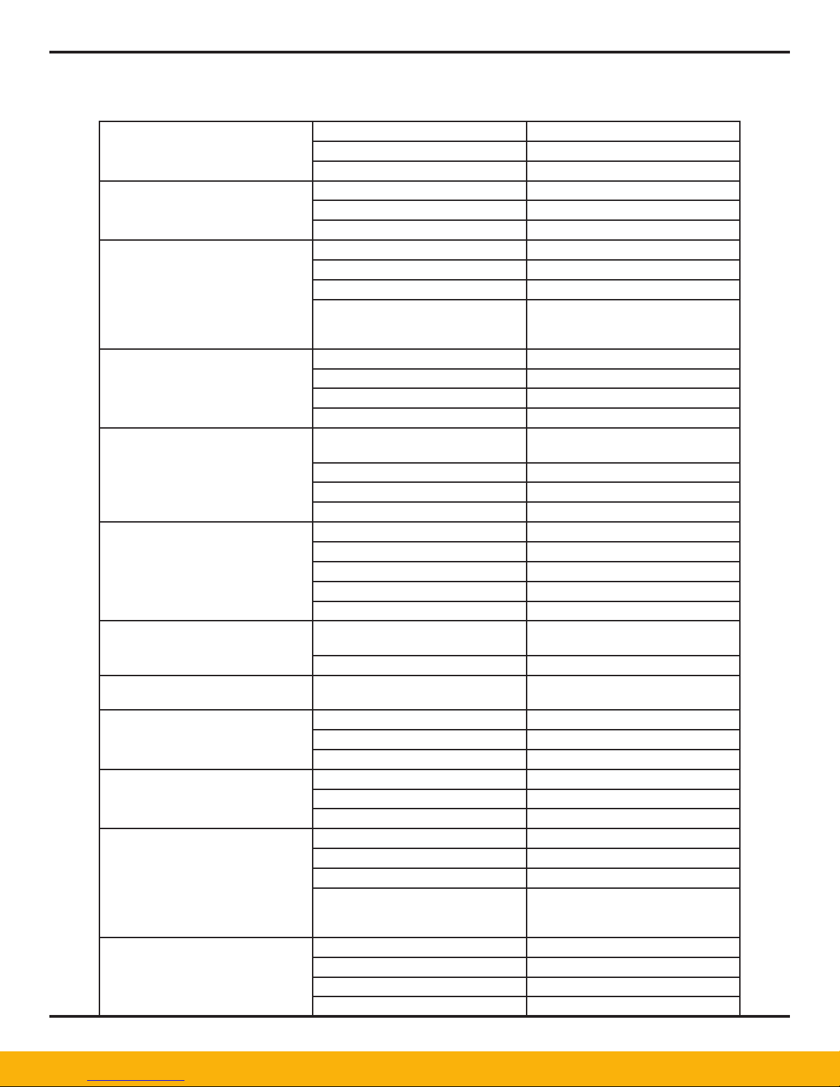
11. Troubleshooting Guide
Exhaust Valve on Drying or
Repressurizing Tower Leaking
Excessive Pressure Drop 1. Pre-lter dirty Replace element
Unit Does Not Fully Repressurize 1. Purge rate too low Adjust purge
Back Pressure in Regenerating
Tower
Inlet or Exhaust Valves not
functioning
No Control Air at Inlet or Exhaust
Valves
Constant Bleed From Control
Solenoid Top Exhaust Port
Constant Bleed From Vent On
Inlet
Exhaust Valve on Drying or
Repressurizing Tower Leaking
Excessive Pressure Drop 1. Pre-lter dirty Replace element
Unit Does Not Fully Repressurize 1. Purge rate too low Adjust purge
Back Pressure in Regenerating
Tower
1. Valve dirty Clean valve
2. Defective diaphragms or O-rings Repair or replace
3. Leaking control solenoid Repair or replace
2. After-lter dirty Replace element
3. Desiccant dirty Replace desiccant
2. Exhaust valves leaking See above
3. Repressurization solenoid faulty Replace solenoid
4. Purge or repressurization orice
plugged
1. Clogged mufers Clean, repair or replace
2. Check valves leaking Clean, repair or replace
3. Purge ow too high Adjust
4. No output from controller Replace fuse or controller
1. Bad diaphragms or O-rings Rebuild valves available kits or
2. No control air See below
3. Control solenoids defective Repair or replace
4. No output from controller Repair or replace
1. Control air shutoff valve closed Open
2. Control air lter dirty Replace Element
3. Leak in control air tubing Repair
4. Control solenoid defective Repair or replace
5. No output from controller Replace fuse or controller
1. Associated inlet or exhaust vavle
defective
2. Dirty or defective control solenoid Clean or replace
1. Defective diaphragms or O-rings Rebuild or replace
1. Valve dirty Clean valve
2. Defective diaphragms or O-rings Repair or replace
3. Leaking control solenoid Repair or replace
2. After-lter dirty Replace element
3. Desiccant dirty Replace desiccant
2. Exhaust valves leaking See above
3. Repressurization solenoid faulty Replace solenoid
4. Purge or repressurization orice
plugged
1. Clogged mufers Clean, repair or replace
2. Check valves leaking Clean, repair or replace
3. Purge ow too high Adjust
4. No output from controller Replace fuse or controller
NOTE - On newer units, orice is a
different color than the rest of the
unit
replace
Rebuild or replace
NOTE - On newer units, orice is a
different color than the rest of the
unit
17
Page 18
DTX10 - DTX80 USER GUIDE
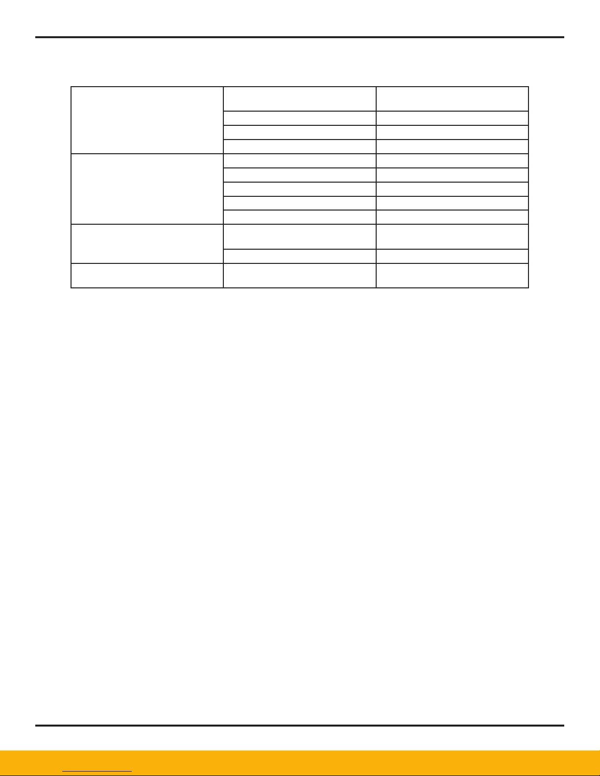
Inlet or Exhaust Valves not
functioning
No Control Air at Inlet or Exhaust
Valves
Constant Bleed From Control
Solenoid Top Exhaust Port
Constant Bleed From Vent On
Inlet
1. Bad diaphragms or O-rings Rebuild valves available kits or
replace
2. No control air See below
3. Control solenoids defective Repair or replace
4. No output from controller Repair or replace
1. Control air shutoff valve closed Open
2. Control air lter dirty Replace Element
3. Leak in control air tubing Repair
4. Control solenoid defective Repair or replace
5. No output from controller Replace fuse or controller
1. Associated inlet or exhaust vavle
defective
2. Dirty or defective control solenoid Clean or replace
1. Defective diaphragms or O-rings Rebuild or replace
Rebuild or replace
18
Page 19
DTX10 - DTX80 USER GUIDE
12. High Humidity
12.1 Principle of Operation
The High Humidity Alarm (HHA) are circuits designed to function in conjunction with a Hygrosensor to
provide on/off control for compressed air dryers. The HHA can also provide an alarm when humidity
conditions exceed or go below a xed setpoint.
Operation of the controller is based on relay actuation at a predetermined resistance value. The
resistance of the humidity sensor (a Dunmore-type lithium chloride element) varies inversely proportional
to the relative humidity to which it is exposed. The controller supplies a constant excitation voltage
to the sensor and the change in resistance is measured. When the relative humidity reaches the
selected setpoint (-20°F, -29°C), the controller detects the corresponding resistance and activates a
single pole, double throw relay.
The controller is set to activate at a predetermined resistance value by using a setplug whose
resistance corresponds to the sensor resistance at a particular relative humidity condition (-20°F).
12.2 System Components
POWER: 12-/220 VAC + 10%, 50-60Hz, 1 Watt DIMENSIONS: PC Board 3.5 x 2.75 x 1.1 inches
OPERATING TEMPERATURE: + 15°F (-9.4°C) to 140°F(60°C) STORAGE TEMPERATURE: -40°F (-40°C)
to +200°F (93°C).
CAUTION! HHA IS POWERED UP DURING THIS PROCEDURE. USE CAUTION NOT TO TOUCH
LIVE EXPOSED TERMINALS.
12.3 Calibration Procedure
1. Remove the sensor input terminals and replace it with the appropriate setplug.
2. Adjust potentiometer P1 to the midpoint between the relay “pull-in” and “drop-out”.
3. Replace the setplug with the sensor. The unit is now ready for operation.
12.4 Precautions, Limitations, and Hazards
The HHA Controller uses 115 VAC. Avoid contact with exposed terminals when performing set
point adjustment.
Never test the sensor with an ohmmeter or other DC measuring device. To do so will permanently
damage the sensor.
Do not expose sensors to humidity’s at which condensation is likely to occur, nor to sprays or water
droplets in ducts and air exhausts.
Do not expose sensors to air stream carrying dust, soot, or other containments, unless properly
protected by bafe, 200 by 200 mesh screen, cellophane, or tissue paper wrap to prevent impingement
of particles on the sensing surfaces.
19
Page 20

DTX10 - DTX80 USER GUIDE
13. Optional DDS
13.1 Quick-Start for Dryers Equipped with DDS
The following steps are all that is normally required for start-up of dryers equipped with the DDS System.
Refer to the remainder of this manual for more detailed information on DDS Operation.
Please read entire Dryer Manual before proceeding.
1. The unit is prewired to the dryer at the factory with the exception of the probe to cable
connection at this time.
2. Purge the sample line of any desiccant dust by opening isolation valve. Use caution as
pressurized air and dust will blowout off open port.
3. Close isolation valve. Install the probe in the 1/2” SAE port provided. Hand tighten the nut,
and then using a wrench tighten the nut another turn and a half.
4. Slowly open the isolation valve to the full open position. It is imperative that the isolation
valve be fully open so that the DDS reads pressure dew point. The sample line is tted
with coiled capillary tubing to control the sample air ow. There must be continuous ow to
obtain an accurate reading.
5. Following exposure of probe to line pressure, allow it to stabilize for 4 hours prior to connecting
the probe cable. Failure to do so may cause premature failure not covered by warranty.
6. After 4 hours connect the probe to the analyzer via the cable provided.
7. The probe and dryer system may require 48 hours or more to reach desired dew point on
initial or subsequent start-ups. High humidity alarms should be disregarded until this time.
8. The unit is normally factory set for -40°F (-40°C) switching and -20°F (-29°C) high
humidity alarm.
9. Dry contacts rated at 120/250 VAG, 2.5 amps are provided for remote annunciation of high
humidity alarm. A linear 4 to 20mA output corresponding to dew point is also provided.
10. Both the switching and high humidity relays are fail-safe. In the event of probe or electronics
failure, the dryer will switch to the xed cycle, the high humidity alarm will activate, and a
diagnostic code will ash on the digital display.
11. Although the probe can be exposed to brief periods of liquid saturation, it can not be exposed
to continuous wet conditions. Remove probe to dry location if these conditions exist.
It is recommended that the probe be returned to the factory once a year for recalibration to standard
gases in order to maintain accuracy. Contact factory for further information.
13.2 Design and Theory of Operation
The DDS is a microprocessor controlled Pressure Dew Point (PDP) analyzer. The DDS
consists of a gold/aluminum oxide sensor probe and an electronics module. The microprocessor
calculates moisture (PDP) that is compensated for temperature and pressure and controls the switching
and alarm set points.
Total dew point control can be obtained with the switching relay, alarm relays, and an optional linear,
isolated 4 to 20mA output corresponding to the PDP.
20
Page 21

DTX10 - DTX80 USER GUIDE
13.3 Mounting the Probe
Probes are shipped loose. Do not misplace or damage the probe. The probe consists of more than
2/3 the value of the unit. When DDS is ordered with a dryer, a sample line for the probe is built
into the dryer outlet. When ordered for eld installation, a sample line will be provided that must
be installed in the piping where it is desired to measure the dew point. A 1/2” NPT port is typically
required.
The probe should be installed vertically with the sensing tip pointing down. Horizontal mounting
is also acceptable. Proper mounting will allow moisture to drip off the tip if a saturation condition
occurs.
Mounting the probe directly in line could possibly cause damage.
Allow the dryer to cycle at least 3 times prior to installing the probe in order to avoid contamination
by desiccant dust. Open the isolation valve and purge the sample line of any collected desiccant
dust. Use caution as pressurized air and dust will then be expelled to atmosphere. Close the
isolation valve and install the probe. Insure that the tip of the probe does not touch the pipe wall.
Adjust the ferrule to the desired insertion length (do not tighten ferrule on the sensing tip) and
tighten the compression tting as follows:
- Hand-tighten the nut.
- Then, using a wrench, tighten the nut one and one- half turns.
Slowly open the isolation valve to full open position. It is imperative that the isolation valve be
fully open so that the DDS reads pressure dew point. The sample line is tted with coiled capillary
tubing to control the sample air ow. There must be continuous ow to obtain an accurate reading.
Following exposure of probe to line pressure, allow it to stabilize for 4 hours prior to connecting
the probe cable. Failure to do so may cause premature failure not covered by warranty.
13.4 Probe to Analyzer Connection
After 4 hours, connect the probe to the analyzer via the cable supplied.
The DDS ordered with a dryer will have the cable prewired to the analyzer. If the unit is being eld
installed, pay close attention to the cable wire colors and make sure the cable shield is grounded.
Refer to applicable electrical.
13.5 Electrical Connection
No other connections are required for factory installed units.
For eld installation refer to applicable drawings and make required power and control corrections.
Note that control wiring for units equipped with switching failure alarm is different than those not
so equipped.
Dry contacts are provided for remote annunciation of High Humidity. A linear 4 to 20mA output is
provided for continuous monitoring of the dew point.
The instrument can now be turned on at any time. However, it should be noted that stable
readings will occur after the sample has come to equilibrium. This can take several hours to
several days depending on the moisture content of the ow, desiccant, piping and probe.
13.6 Troubleshooting
BLANK DISPLAY (with the power turned on) - this is an indication of a power line fault.
21
Page 22
DTX10 - DTX80 USER GUIDE
Check the power connection. If the display is still blank, the display is at fault. Consult the factory.
Probe Recalibration and Replacement
- The recommended calibration interval is one year to maintain accuracy (+/- 1%).
- Consult the factory for recalibration procedure.
13.7 DDS Display:
The display is factory set to indicate either degrees ºF or degrees ºC.
There are four Set Points. To view depress the ‘down’ arrow (right button). Each time the down
arrow pushbutton is depressed, the display will cycle to the next set point value. The Set Point
number is displayed followed by the set point value. For example: ‘SP2” followed by,‘-20’
This cycling will continue until the ‘down’ arrow pushbutton is depressed to advance to the next
Set Point.
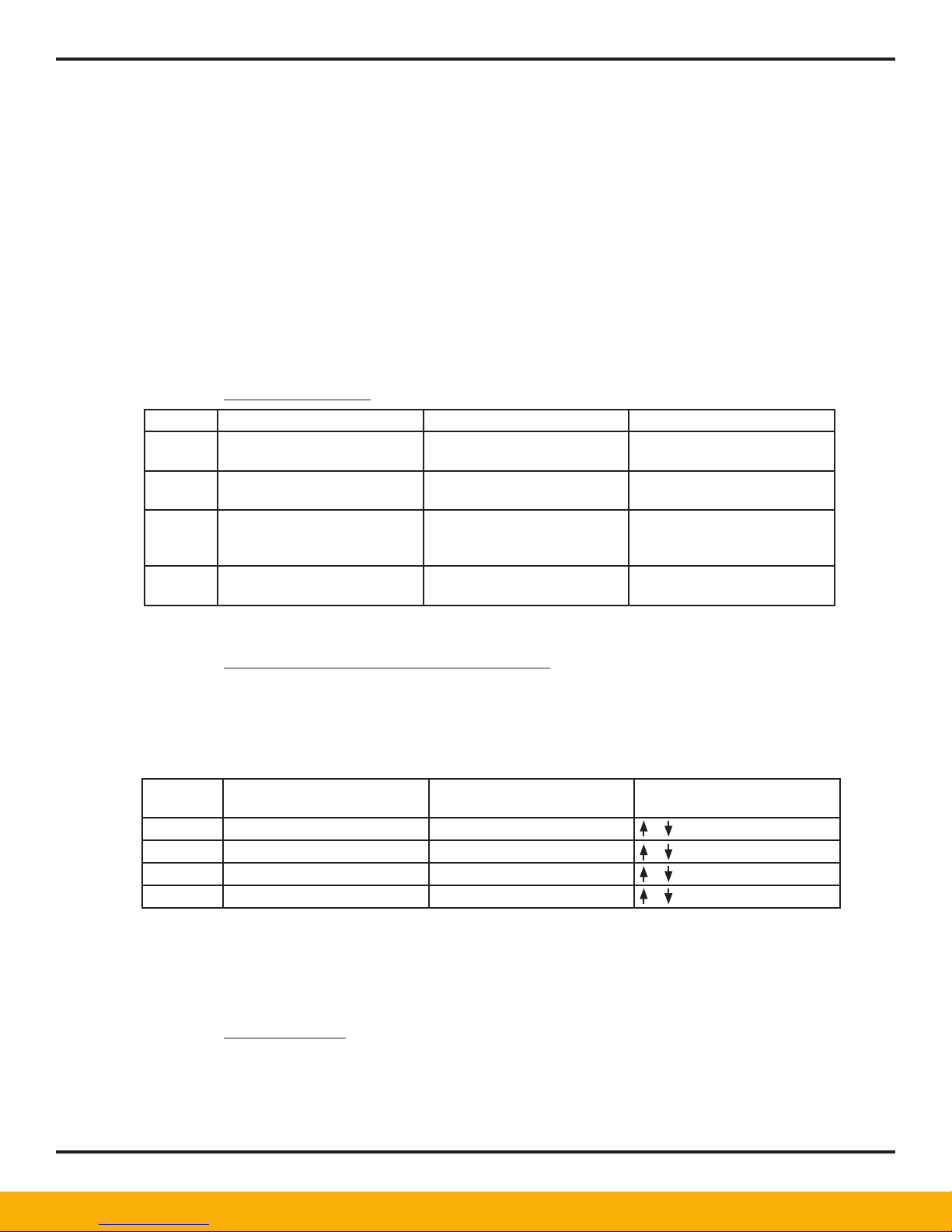
The four Set Points are:
Display Description Default = °F or °C Indication
SP3’ DEWPOINT ALARM (Default = -°20 / -°28.9) RED ‘HIGH HUMIDITY’ PILOT
SP4’ OPEN PROBE ALARM (Default = -°199.9 / °128.8) RED ‘HIGH HUMIDITY’ PILOT
SP2’ NOT USED (note - the display LED will
SP1’ POWER SAVE MODE ON (Default = -40° / -40°) AMBER Power Save ‘ON’
LIGHT
LIGHT
AMBER Power Save ‘ON’
illuminate at a ‘zero’ or ‘+’ dew
point
PILOT LIGHT
To go back to displaying Dew Point, depress the ‘PROG’ pushbutton (left button).
CHANGE SET POINT DEFAULT TO NEW VALUES:
The Set Points can be changed to any desired value. To change to a new set point value, depress
both the ‘PROG’ (left button) and the ‘down ‘arrow (right button) simultaneously. The display will
go into the ‘Program Set Point’ mode. (NOTE: once into the program mode it is necessary to
complete advancing through all the steps to save any changed values). There are four steps to
each Set Point. These steps are as follows:
Display Setting Description Display Default Push Buttons to Change
Value
SPx SET POINT VALUE -20° (see above) or then ‘PROG’ to advance
do DELAY-ON MAKE 0 or then ‘PROG’ to advance
dob DELAY-ON BREAK 0 or then ‘PROG’ to advance
HySe HYSTERESIS 0 or then ‘PROG’ to advance
If no change is desired at any step within process, simply depress the ‘PROG’ to advance through
the program cycle. Once all four Set Points (and four settings per set point) are completed, the
display will go back to displaying the dew point. If no activity is detected while in the program
mode, after 15 seconds the unit will go back to displaying Dew Point with no changes to the
preceding step prior to depressing the ‘PROG’ pushbutton.
OTHER SETTINGS:
All other settings (4-20mA ‘IN’, and 4-20mA ‘OUT;) have been factory set. IMPORTANT: it is
possible to inadvertently access these program menus, it is advisable to not change any range
settings; as this would make the unit not respond correctly. For DDS units with three (3) wire
probes, the following information will apply to the 4-20mA outputs on J3, pin 16 =(+) and pin 17
=(-). The Dew Point range is as follows:
22
Page 23

DTX10 - DTX80 USER GUIDE
DEGREE °F -148 @ 4mA through to +68 @ 20mA
DEGREE °C -100 @ 4mA through to +20.0 @ 20mA
14. Optional Pre/After Filters
Receiving and Inspection
Upon receipt of the lter(s), immediately check for damage that may have occurred during shipping. If there is
any damage, do not install or attempt to repair the lter. File a claim with the shipping company and contact
either your local distributor or contact manufacturer’s customer service department for further instructions.
Since the lter is shipped F.O.B. factory, the carrier is not covered by lter warranty.
WARNING! FAILURE OR IMPROPER SELECTION OR IMPROPER USE OF THE PRODUCTS AND/OR
SYSTEMS DESCRIBED HEREIN OR RELATED ITEMS CAN CAUSE SEVERE INJURY OR PROPERTY DAMAGE.
Installation
All lters, coalescer, adsorbers should be installed at the highest pressure point available, and as near as
possible to the equipment to be protected with a drip leg immediately upstream. The coalescer should be in a
visible and easily accessible location for periodic draining and maintenance.
All lters should be selected based on compressed air ow rate and pressure, not on the basis of pipe size. If
new piping is installed, pipe size must also be selected on the basis of ow rate and pressure. Be sure all piping
is supported.
Filters should be piped in accordance with the instruction tags, ow arrows, and “IN” and “OUT” labels
supplied with the lter. See recommended system installation diagram in this manual.
Before lter installation, the customer may wish to install a pressure relief device in accordance with paragraphs
UG-125 through UG-136 of the ASME Boiler and Pressure Code section VIII-division I. You may also wish to
check with local requirements.
Filter Bypass
A three-valve bypass around the lter is recommended so that the elements can be charged without shutting
down the branch or complete air system. Piping should not be allowed to place any stress on the lter
connections.
For systems that can not tolerate unltered air during element replacement, a second lter should be installed in
the bypass. See installation diagrams.
Element Replacement
As the lter is used, the replaceable element will become plugged with particles from the air stream. The
gradual buildup of these particles will cause an ever increasing pressure drop through the element. This
pressure drop will be indicated by the differential pressure gage that is provided with the lter. The lter should
be changed when the indicator suggests the element is plugged. The increasing pressure drop will cause a
reduction in the air system efciency.
WARNING! COMPLETELY VENT INTERNAL AIR PRESSURE TO ATMOSPHERE BEFORE
DISASSEMBLING FILTER.
23
Page 24

DTX10 - DTX80 USER GUIDE
Cast Filters
• Relieve internal pressure by opening the manual vent valve.
• Disconnect drain lines at manual and automatic drain valves (if applicable).
• Unscrew lter collar from head of lter and remove bowl.
• Unscrew retaining cap from rod.
• Remove used lter element and dispose of in accordance with local regulations.
• Clean any debris from bowl and insert new element.
• Examine condition of O-rings
• Screw retaining cap on rod until snug without damaging the new element.
• Reattach drains.
• Repressurize slowly to prevent element damage and leak check.
Filter Drainage
The lter sump in the bottom of each lter is a critical part of the ltration system. The liquids that
accumulate here must be drained at regular intervals, in order to prevent the condensate from being re-in
trained in the ltered air. A typical drain system should consist of an automatic drain ball valve. (Applies to
coalescing lters only.)
Outdoor Installation
Heat tracing of sump area and drain lines are required for installations that are exposed to ambients of 32°F
or lower.
Application Notes
FILTERING FACTS:
• All compressed air is “saturated” with moisture unless its pressure dew point has been reduced by
drying. Filtration does not change the moisture or oil dew point of the air. Filtration or coalescing ONLY
removes particles, liquid and aerosols. They can not remove vapors.
• Coalescing should be done at the lowest temperature possible.
• Oil and water vapors condense as the temperature is lowered.
24
Page 25

DTX10 - DTX80 USER GUIDE
Element Initial PSID Replacement Element at PSID
Coalescer - Dry New 1.5 N/A
Coalescer - Wet New 2.5 6 - 8
Adsorber 1 4 - 6
Particulate 1.5 4 - 6
15. Warranty
The Parker Warranty Philosophy...
Warranty can be dened as a protection of investment. Warranty policies can come in all different shapes and
sizes; however, the most important attribute to a successful policy is its fairness to all parties involved. This
brings us to the explanation of components that make up Parker Warranty Philosophy.
Warranty Procedure...
Parker believes in giving the most expedient service possible to our customers. In order to accomplish this
the most important step for our customer is to call us (1-855-5TRYFAF) immediately in the event of a potential
warranty situation. The phone call serves several purposes;
• It puts the customer in direct communication with the factory and assures them of factory support.
• It helps us to diagnose the problem and perhaps remedy it over the phone. This saves everyone
time. In most cases we can determine the root cause of the failure through a simple phone call.
• It helps us to assess any parts that may be needed for repair. This eliminates time and travel by a
service company making one trip with parts in hand.
• It helps us to determine situations non related to the dryer. After the phone call has been placed, and
if service is necessary, we will authorize a service house in close proximity to the customer.
It is important when a call is placed to us for a potential warranty situation, that the following information be
provided:
. Model and serial number.
. Start-up date.
. Company name.
. Dryer location.
. Phone number.
. Contact person.
. Specic nature of complaint
(Diagnostic code, high dew point, etc.). Important: Parker reserves the right to deny any claim submitted
without our knowledge and proper authorization.
Warranty Parts and Returns...
In the event a part is required to complete a warranty repair the following steps will occur:
1. A standard parts order must be placed with our customer service department (1-855-5TRYFAF),
along with a purchase order number.
2. The customer that placed the order will receive an invoice for the part. This is for memo billing only.
The invoice will also contain a Return Authorization Number (RMA).
25
Page 26
DTX10 - DTX80 USER GUIDE
Email to: [email protected]
WARRANTY REGISTRATION
IMPORTANT! E-Mail Today!
We are here to help. For more information on service or installation call the Service Department at 1-855-587-9323.
Model # Serial #
Company
Address
City State/Province Zip
Telephone Contact
Title Department
Date Purchased Date installed
Purchased From
Fold and Seal and your Service Warranty will be registered immediately.
COMMENTS
Please indicate a response on a scale of
(1) being the lowest to (5) being the highest
Condition of Arrival
Ease of Installation
Ease of Start-Up
Product Quality
FINAL OPERATION CHECK LIST
Inlet air temperature is
Inlet PSIG is
The dew point temperature controller reads between
and
Air compressor HP
Is the dryer a minimum of 3’ from any structure on all sides?
Technical Assistance
Clarity of Instruction/Warranty Manual
The Y strainer for drains has been cleaned after first 8 hours of
operation Yes No
What are your thoughts on the operation of the dryer?
Why did you choose this manufacturer?
, or Max SCFM is
Yes No
What could we do better?
26
Page 27

DTX10 - DTX80 USER GUIDE
Appendix - Spare Parts
27
Page 28

DTX10 - DTX80 USER GUIDE
Appendix - Drawings
28
Page 29

Worldwide Filtration Manufacturing Locations
North America
Compressed Air Treatment
Filtration & Separation/Balston
Haverhill, MA
978 858 0505
www.parker.com/balston
Finite Airtek Filtration
Airtek/domnick hunter/Zander
Lancaster, NY
716 686 6400
www.parker.com/faf
Finite Airtek Filtration/Finite
Oxford, MI
248 628 6400
www.parker.com/nitelter
Engine Filtration &
Water Purification
Racor
Modesto, CA
209 521 7860
www.parker.com/racor
Holly Springs, MS
662 252 2656
www.parker.com/racor
Beaufort, SC
843 846 3200
www.parker.com/racor
Racor – Village Marine Tec.
Gardena, CA
310 516 9911
desalination.parker.com
Parker Sea Recovery
Carson, CA
310 637 3400
www.searecovery.com
Hydraulic Filtration
Hydraulic Filter
Metamora, OH
419 644 4311
www.parker.com/hydrauliclter
Laval, QC Canada
450 629 9594
www.parkerfarr.com
Process Filtration
domnick hunter Process Filtration
Oxnard, CA
805 604 3400
www.parker.com/processltration
Madison, WI
608 824 0500
www.scilog.com
Phoenixville, PA
610 933 1600
www.parker.com/processltration
Aerospace Filtration
Velcon Filtration
Colorado Springs, CO
719 531 5855
www.velcon.com
Europe
Compressed Air Treatment
domnick hunter Filtration & Separation
Gateshead, England
+44 (0) 191 402 9000
www.parker.com/dhfns
Parker Gas Separations
Etten-Leur, Netherlands
+31 76 508 5300
www.parker.com/dhfns
Hiross Zander
Padova Business Unit
Padova, Italy
+39 049 9712 111
www.parker.com/hzd
Hiross Zander
Essen Business Unit
Essen, Germany
+49 2054 9340
www.parker.com/hzd
Engine Filtration &
Water Purification
Racor
Dewsbury, England
+44 (0) 1924 487 000
www.parker.com/rfde
Racor Research & Development
Stuttgart, Germany
+49 (0)711 7071 290-10
www.parker.com/rfde
Hydraulic Filtration
Hydraulic Filter
Arnhem, Holland
+31 26 3760376
www.parker.com/hfde
Urjala Operation
Urjala, Finland
+358 20 753 2500
www.parker.com/hfde
Condition Monitoring Centre
Norfolk, England
+44 (0) 1842 763 299
www.parker.com/hfde
Parker Kittiwake
West Sussex, England
+44 (0) 1903 731 470
www.kittiwake.com
Parker Procal
Peterborough, England
+44 (0) 1733 232 495
www.kittiwake.com
Process Filtration
domnick hunter Process Filtration
Birtley, England
+44 (0) 191 410 5121
www.parker.com/processltration
Parker Twin Filter BV
Zaandam, Netherlands
+31(0)75 655 50 00
www.twinlter.com
Asia Pacific
Australia
Castle Hill, Australia
+61 2 9634 7777
www.parker.com/australia
China
Shanghai, China
+86 21 5031 2525
www.parker.com/china
India
Navi Mumbai, India
+91 22 651 370 8185
www.parker.com/india
Parker Fowler
Bangalore, India
+91 80 2783 6794
www.johnfowlerindia.com
Japan
Tokyo, Japan
+81 45 870 1522
www.parker.com/japan
Parker Techno
Osaka, Japan
+81 66 340 1600
www.techno.taiyo-ltd.co.jp
Korea
Hwaseon-City
+82 31 359 0852
www.parker.com/korea
Singapore
Jurong Town, Singapore
+65 6887 6300
www.parker.com/singapore
Thailand
Bangkok, Thailand
+66 2186 7000
www.parker.com/thailand
Latin America
Parker Comercio Ltda.
Filtration Division
Sao Paulo, Brazil
+55 12 4009 3500
www.parker.com/br
Pan American Division
Miami, FL
305 470 8800
www.parker.com/panam
Africa
Aeroport Kempton Park, South Africa
+27 11 9610700
www.parker.com/africa
© 2014 Parker Hannin Corporation. Product names are trademarks or registered trademarks of their respective companies. MAN-DTX5
Parker Hannin Corporation
Finite Airtek Filtration Division
4087 Walden Avenue
Lancaster, NY 14086
phone 716 686 6400
www.parker.com/faf
 Loading...