

Page 1
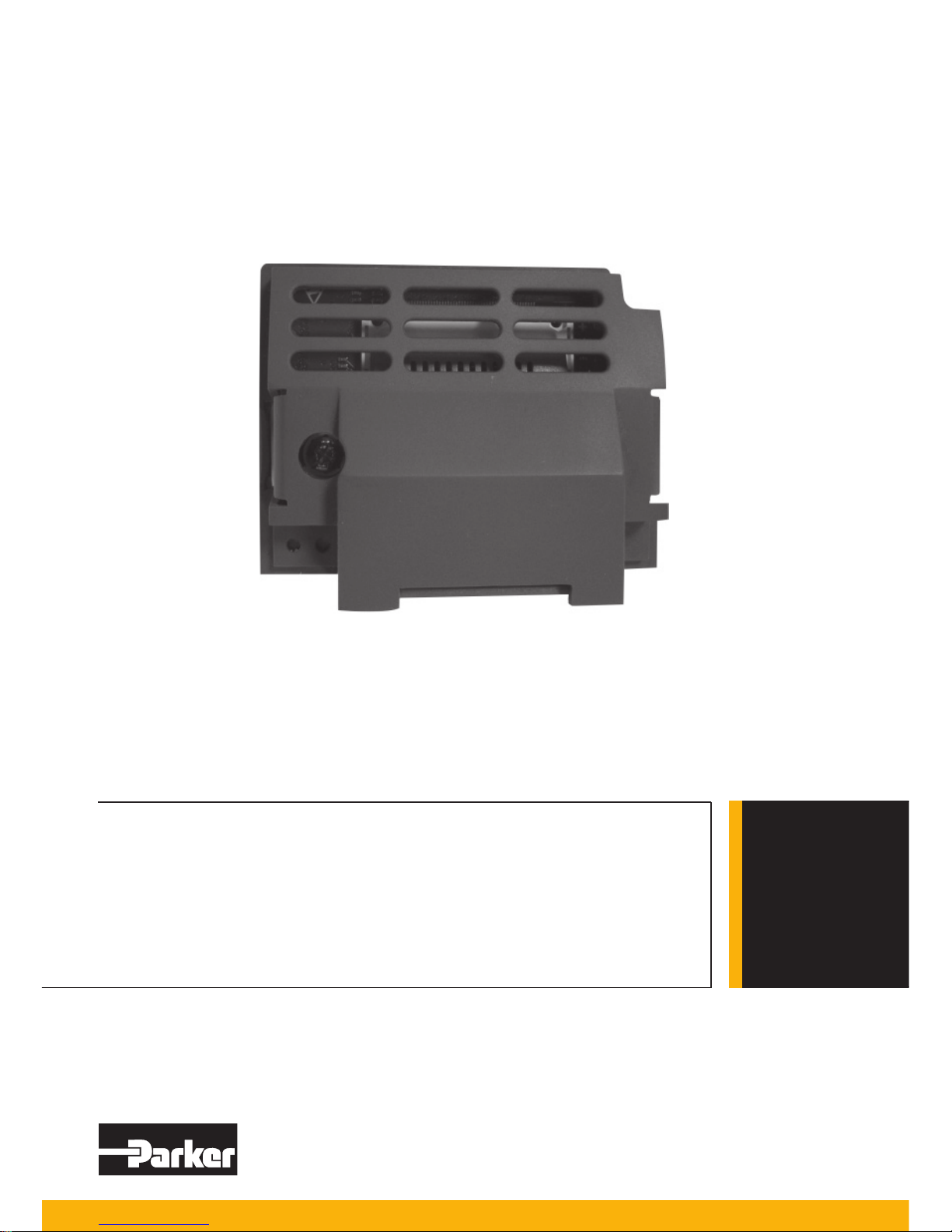
Option Modules
Profi bus DP-V1 Communications Option
HA501837U001 Issue 1
Technical Manual
aerospace
aerospace
climate control
climate control
electromechanical
fi ltration
fi ltration
fl uid & gas handling
fl uid & gas handling
hydraulics
hydraulics
pneumatics
pneumatics
process control
process control
sealing & shielding
sealing & shielding
ENGINEERING YOUR SUCCESS
www.comoso.com
Page 2

www.comoso.com
Page 3

AC30 Profibus DP-V1 Option
Technical Manual
HA501837U001 Issue 1
Copyright 2012 Parker Hannifin Manufacturing Limited
All rights strictly reserved. No part of this document may be stored in a retrieval system, or transmitted in
any form or by any means to persons not employed by a Parker company without written permission from
Parker Hannifin Ltd. Although every effort has been taken to ensure the accuracy of this document it may
be necessary, without notice, to make amendments or correct omissions. Parker cannot accept
responsibility for damage, injury, or expenses resulting therefrom.
Parker Hannifin Manufacturing Limited is referred to throughout this document as Parker.
WARR ANTY
The general terms and conditions of sale of goods and/or services of Parker Hannifin Europe
Sàrl’s, Luxembourg, Switzerland Branch, Etoy, apply to this product unless otherwise agreed.
The terms and conditions are available on our website
www.parker.com/termsandconditions/switzerland.
www.comoso.com
Page 4

FAILURE OR IMPROPER SELECTION OR IMPROPER USE OF THE PRODUCTS
DESCRIBED HEREIN OR RELATED ITEMS CAN CAUSE DEATH, PERSONAL INJURY
AND PROPERTY DAMAGE.
This document and other information from Parker-Hannifin
Corporation, its subsidiaries and authorized distributors
provide product or system options for further investigation by
users having technical expertise.
The user, through its own analysis and testing, is solely
responsible for making the final selection of the system and
components and assuring that all performance, endurance,
maintenance, safety and warning requirements of the
application are met. The user must analyze all aspects of the
application, follow applicable industry standards, and follow
the information concerning the product in the current product
catalog and in any other materials provided from Parker or its
subsidiaries or authorized distributors.
To the extent that Parker or its subsidiaries or authorized
distributors provide component or system options based upon
data or specifications provided by the user, the user is
responsible for determining that such data and specifications
are suitable and sufficient for all applications and reasonably
foreseeable uses of the components or systems.
The above disclaimer is being specifically brought to the
user’s attention and is in addition to and not in substitution to
the Exclusions and Limitations on Liability which are set out in
the terms and conditions of sale.
www.comoso.com
Page 5
Safety Information
Requirements
IMPORTANT: Please read this information BEFORE installing the equipment.
Intended Users
This manual is to be made available to all persons who are required to install, configure or
service equipment described herein, or any other associated operation.
The information given is intended to highlight safety issues, EMC considerations, and to
enable the user to obtain maximum benefit from the equipment.
Complete the following table for future reference detailing how the unit is to be installed
and used.
INSTALLATION DETAILS
Model Number
(see product label)
Where installed
(for your own information)
Application Area
The equipment described is intended for industrial motor speed control
utilising AC induction or AC synchronous machines.
Personnel
Installation, operation and maintenance of the equipment should be carried
out by competent personnel. A competent person is someone who is
technically qualified and familiar with all safety information and established
safety practices; with the installation process, operation and maintenance of
this equipment; and with all the hazards involved.
Product Warnings
DANGER
Risk of electric
shock
WARNING
Hot
surfaces
Caution
Refer to
documentation
Earth/Ground
Protective
Conductor
Terminal
CAUTION!
APPLICATION RISK
• The specifications, processes and circuitry described herein are for guidance only and
may need to be adapted to the user’s specific application. We cannot guarantee the
suitability of the equipment described in this Manual for individual applications.
RISK ASSESSMENT
Under fault conditions, power loss or unintended operating conditions, the drive may not
operate as intended. In particular:
• Stored energy might not discharge to
safe levels as quickly as suggested,
and can still be present even though
the drive appears to be switched off
• The motor's direction of rotation might not
be controlled
• The motor speed might not be controlled
• The motor might be energised
A drive is a component within a drive system that may influence its operation or effects
under a fault condition. Consideration must be given to:
• Stored energy
• Supply
disconnects
• Sequencing
logic
• Unintended operation
www.comoso.com
Page 6

Safety Information
DANGER! - Ignoring the following may result in injury
1. This equipment can endanger life by
exposure to rotating machinery and high
voltages.
2. The equipment must be permanently
earthed due to the high earth leakage
current, and the drive motor must be
connected to an appropriate safety earth.
3. Ensure all incoming supplies are isolated
before working on the equipment. Be
aware that there may be more than one
supply connection to the drive.
4. There may still be dangerous voltages
present at power terminals (motor output,
supply input phases, DC bus and the
brake, where fitted) when the motor is at
standstill or is stopped.
5. For measurements use only a meter to IEC
61010 (CAT III or higher). Always begin using
the highest range.
CAT I and CAT II meters must not be used on
this product.
6. Allow at least 5 minutes for the drive's
capacitors to discharge to safe voltage levels
(<50V). Use the specified meter capable of
measuring up to 1000V dc & ac rms to confirm
that less than 50V is present between all
power terminals and between power terminals
and earth.
7. Unless otherwise stated, this product must
NOT be dismantled. In the event of a fault the
drive must be returned. Refer to "Routine
Maintenance and Repair".
WARNING! - Ignoring the following may result in injury or damage to equipment
SAFETY
Where there is conflict between EMC and Safety requirements, personnel safety shall
always take precedence.
• Never perform high voltage resistance
checks on the wiring without first
disconnecting the drive from the circuit
being tested.
• Whilst ensuring ventilation is sufficient,
provide guarding and /or additional
safety systems to prevent injury or
damage to equipment.
• When replacing a drive in an application
and before returning to use, it is
essential that all user defined
parameters for the product’s operation
are correctly installed.
• All control and signal terminals are SELV, i.e.
protected by double insulation. Ensure all
external wiring is rated for the highest system
voltage.
• Thermal sensors contained within the motor
must have at least basic insulation.
• All exposed metalwork in the Inverter is
protected by basic insulation and bonded to a
safety earth.
• RCDs are not recommended for use with this
product but, where their use is mandatory,
only Type B RCDs should be used.
EMC
• In a domestic environment this product
may cause radio interference in which
case supplementary mitigation measures
may be required.
• This equipment contains electrostatic
discharge (ESD) sensitive parts. Observe
static control precautions when handling,
installing and servicing this product.
• This is a product of the restricted sales
distribution class according to IEC 61800-3.
It is designated as “professional equipment”
as defined in EN61000-3-2. Permission of
the supply authority shall be obtained before
connection to the low voltage supply.
www.comoso.com
Page 7

Disposal
Waste Electrical and Electronic Equipment (WEEE)
Waste Electrical and Electronic Equipment - must not be
disposed of with domestic waste.
It must be separately collected according to local legislation and
applicable laws.
Parker Hannifin Company, together with local distributors and in accordance
with EU directive 2002/96/EC, undertakes to withdraw and dispose of its
products, fully respecting environmental considerations.
For more information about how to recycle your Parker supplied waste
equipment, please contact your local Parker Service Centre.
Packaging
During transport our products are protected by suitable packaging. This is
entirely environmentally compatible and should be taken for central disposal
as secondary raw material.
www.comoso.com
Page 8

Contents .......................................................................................................... Page No.
AC30 Profibus DP-V1 Option ...................................................................................... 1
Introduction ....................................................................................................... 1
Features ..................................................................................................... 1
The Product Code ............................................................................................. 1
Installation ......................................................................................................... 2
Connecting to the Profibus Network .................................................................. 4
Wiring Diagram Example ............................................................................ 7
LEDs ................................................................................................................. 7
Operation (OP) Mode LED .......................................................................... 7
Status (ST) LED .......................................................................................... 7
Configuration..................................................................................................... 8
Node Address ............................................................................................. 8
Process Data .............................................................................................. 8
Example Configuration .................................................................................... 10
Configuration Summary ............................................................................ 10
Example Using a SIMATIC PLC ................................................................ 10
Configuring the AC30 ................................................................................ 14
Acyclic Data Exchange.................................................................................... 16
Overview................................................................................................... 16
Parameter Read / Write with Call .............................................................. 17
Example Acyclic Data Exchange ..................................................................... 19
Lost Communications Trip ............................................................................... 21
Supervised Parameter .............................................................................. 21
Comms Break Trip .................................................................................... 21
Diagnostic Event ............................................................................................. 22
Parameters ..................................................................................................... 23
Configuration Parameters ......................................................................... 23
Runtime Parameters ................................................................................. 25
Diagnostic Parameters .............................................................................. 26
Troubleshooting .............................................................................................. 30
Hardware Mismatch .................................................................................. 30
Invalid Configuration ................................................................................. 30
PLC Indication .......................................................................................... 30
Appendix A – Array Parameter Numbers ......................................................... 31
Array Example .......................................................................................... 31
Appendix B – Data Types ................................................................................ 31
www.comoso.com
Page 9

1
AC30 Profibus DP-V1 Option
AC30 PROFIBUS DP-V1 OPTION
Introduction
Features
• Profibus DP-V1
• Up to 12Mbps transmission rate
• Galvanically isolated bus via DB9F female connector
• Status and Operation Mode LEDs
• Up to a total of 152 bytes of cyclic I/O data
• Up to 68 bytes of Class 1 and Class 2 acyclic data
• Up to 152 bytes of configuration data
• GSD file provided
The Product Code
The product code for the Profibus DP-V1 Option is:
7003-PB-00
www.comoso.com
Page 10
2
AC30 Profibus DP-V1 Option
Installation
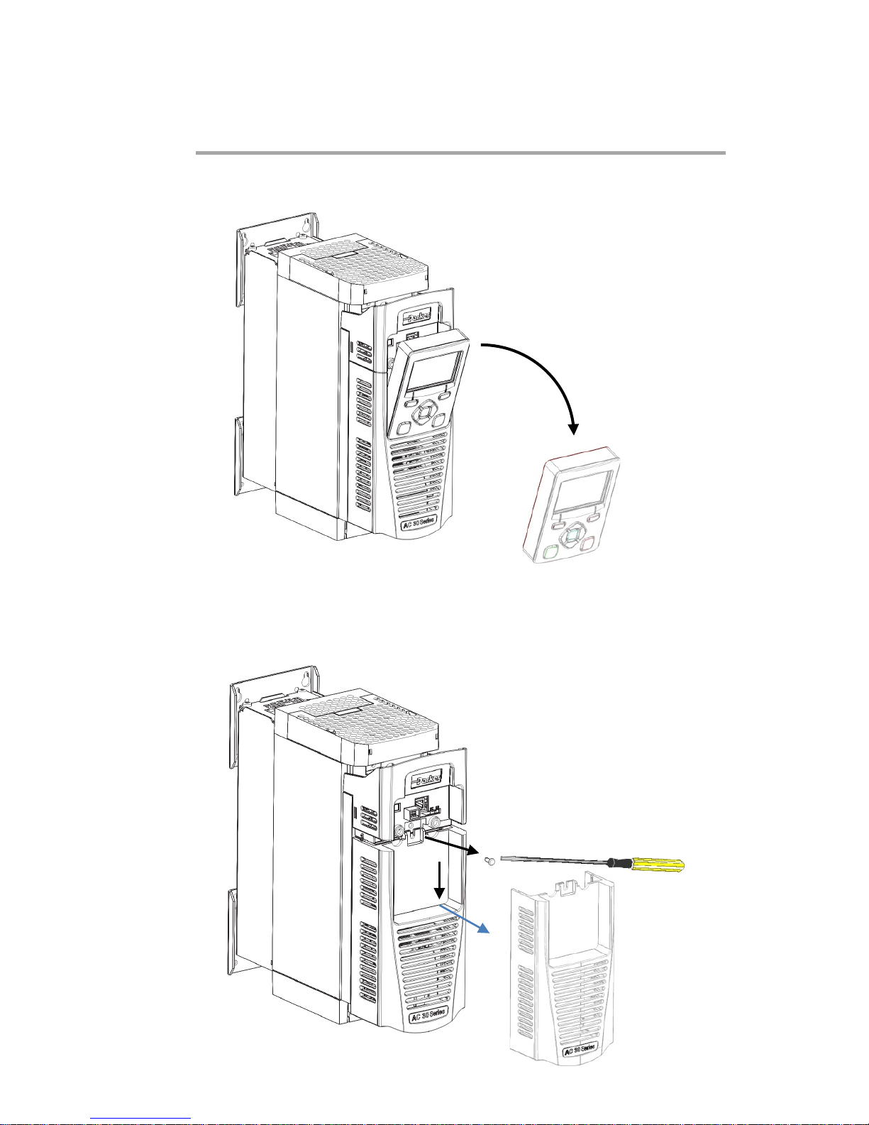
1. Remove the Grapical Keypad (GKP) by pulling from the top down, and
remove.
2. After removing the screw slide the control module lower cover down
slightly and then remove.
www.comoso.com
Page 11
3
AC30 Profibus DP-V1 Option
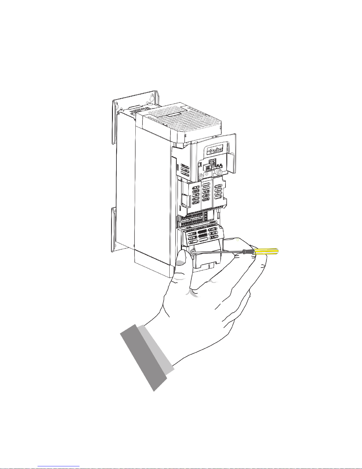
3. Click the Option into place and tighten the retaining screw, as shown.
4. Slide and click back the control module lower cover, tighten the retaining
screw and slot back the GKP
www.comoso.com
Page 12
4
AC30 Profibus DP-V1 Option
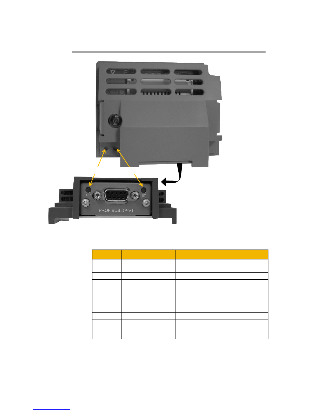
Connecting to the Profibus Network
Pin Signal Description
1 - 2 -
3
B Line
Positive RxD/TxD RS485 level
4
RTS
Request to send
5
GND Bus
Isolated ground
6
+5V Bus Output
Isolated +5V termination (shortcircuit protected)
7 - 8 A Line
Negative RxD/TxD RS485 level
9 -
Housing
Cable Shield
Connected to protective earth via
a filter
Note: It is possible to make serial communications operate without
adhering to the following recommendations; however, the
recommendations will promote greater reliability.
Pin Numbers
1 2 3 4 5
6 7 8 9
OP ST
PROFIBUS DP-V1
LEDs
Operation Status
www.comoso.com
Page 13

5
AC30 Profibus DP-V1 Option
Cable Specification
PROFIBUS DP-V1 cable uses a specific colour code (red/green). You
should maintain this colour code throughout your network. The cable
has a single twisted pair with overall shielding.
The bus line is specified in IEC 61158 and it can be used in
accordance with the table below.
Cable Parameters
PROFIBUS line
Surge impedance in Ω
135 … 165
Capacitance per unit length (pF/m) < 30
Loop resistance (Ω/km)
110
Core diameter (mm) 0.64
Core cross-section (mm2) > 0.34
Note: Belden B3079E cable meets the above specification.
PROFIBUS DP-V1 Connectors
You should use connectors recommended by Profibus. These
connectors will have a shield clamp providing shield continuity and will
help to ensure good noise immunity of your network.
We recommend the use of the horizontal Erbic range of PROFIBUSDP connectors from ERNI:
♦ ERNI Part number 103648, grey - used on all
nodes in the middle of the network
♦ ERNI Part number 103649, yellow - termination
connector
♦ ERNI Part number 134728, grey - includes
switchable termination
For further information, visit www.erni.com
www.comoso.com
Page 14

6
AC30 Profibus DP-V1 Option
Terminators
Failure to terminate a network correctly can reduce the noise immunity
of the network and affect performance.
A termination resistor must be fitted at each end of the network to
prevent interference.
If too many resistors are fitted to the network, the resulting reduced
signal levels may cause nodes to miss bits of information. If network
overload becomes excessive, the reduced signal levels may prevent
the nodes from detecting any activity.
Connect terminating resistors to the end drives as shown below. (All
resistors ±5%, minimum ¼ Watt).
Data line B (3)
Data line A (8)
GND (5)
VP (6)
390
Ω
220
Ω
390
Ω
Terminating resistors
on the bus
Signals at connector
Pin number in parentheses
Repeaters
The maximum number of nodes allowed on a single PROFIBUS DPV1 network segment is 32. A repeater can be used to extend the
network length and/or to allow more than 32 nodes to be connected.
Note: CNTR-P (Pin Number 4) is a TTL level signal that can
be connected to a repeater. Most repeaters
automatically switch between transmitting and receiving
and so do not need this connection.
www.comoso.com
Page 15
7
AC30 Profibus DP-V1 Option
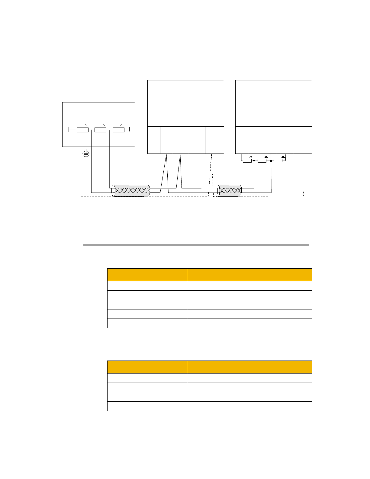
Wiring Diagram Example
LEDs
Operation (OP) Mode LED
State Indication
Off
Not online / No power
Green
Online, data exchange
Flashing Green
Online, clear
Flashing Red (1 flash)
Parameterization error
Flashing Red (2 flashes)
Configuration error
Status (ST) LED
State Indication
Off
No power or not initialised
Green
Initialised
Flashing Green
Initialised, diagnostic event present
Red
Exception error
PLC/master
A B
AC30 Profibus DP-V1
Option
AC30 Profibus DP-V1
Option
390 220 390
0V
5V
390 220 390
5 8 3 6 SHIELD
GND A B +5V
Bus Line Line Bus
Output
5 8 3 6 SHIELD
GND A B +5V
Bus Line Line Bus
Output
www.comoso.com
Page 16

8
AC30 Profibus DP-V1 Option
Configuration
The option requires configuration of the slave node address and
mapping of the process data to the master. The baud rate is detected
automatically. Note that some communication parameters only
become active after the AC30 leaves the configuration state.
The 0044 Comms Required parameter must be set to PROFIBUS
DPV1.
Node Address
The 0238 Profibus Node Address parameter must be set to the
required address for the slave. The range is the 0 -125. If the
address is set to 126 then the SSA (Set Slave Address) will be used,
which enables a master or configuration tool to set the node address.
Note: The default value is 0. This value should be changed before
connecting to a network.
Process Data
The cyclic I/O data is configured by using the read and write process
data mapping tables in the AC30. These tables are two parameter
arrays in which AC30 parameter numbers may be added.
At least one AC30 parameter must be mapped to the process data.
String-type parameters may not be mapped.
Read Mapping
The read process data represents cyclic data sent from the PLC to the
AC30. Only writable AC30 parameters, that are not configuration
parameters, may be added to the read process data.
Write Mapping
The write process data represents cyclic data sent from the AC30 to
the PLC.
Mapping Arrays
Parameter arrays may be added into the process data, however this
could lead to large amounts of data being passed across the
communications. An alternative is to only reference the element(s) of
the array required. This is possible as each element of a parameter
array has its own parameter number. See the Appendix A– Array
Parameter Numbers.
www.comoso.com
Page 17

9
AC30 Profibus DP-V1 Option
Default Mapping
The process data mapping will contain a factory default mapping. The
default mapping may be overwritten if required.
Modules
The GSD file defines a number of modules. When configuring the
PLC, the modules may be added to the slave device slots as required.
These modules map to the process data in the order in which they are
added.
The modules relevant to the AC30 are:
Module Maps to parameter
Input 1 byte
Write process data – 1-byte parameters
Input 1 word
Write process data – 2-byte parameters
Input 2 words
Write process data – 4-byte parameters
Output 1 byte
Read process data – 1-byte parameters
Output 1 word
Read process data – 2-byte parameters
Output 2 words
Read process data – 4-byte parameters
The size of a parameter may be determined from its data type. The
relationship between the AC30 parameter and Profibus data types is
given in Appendix B – Data Types.
If parameter arrays are to be included in the process data mapping,
then add as many modules as there are indexes in the array. Each
module must be the same size as the element of the array.
Cyclic Data Exchange
Cyclic data exchange will occur when an MS0 connection is
established, i.e. when the Profibus State is IDLE (master mode =
clear) or PROCESS ACTIVE (master mode = operate). However, the
read process data will only update the mapped parameters when in
the PROCESS ACTIVE state.
On a transition into the PROCESS ACTIVE state all read process
mapped parameters will be updated.
When in the PROCESS ACTIVE state the read process mapped
parameters will all update only when a change in the read process
data occurs.
www.comoso.com
Page 18
10
AC30 Profibus DP-V1 Option
Example Configuration
Configuration Summary
Communications Settings
Node Address 3
Read Process Mapping Table Data
Type
Bytes PLC
Module
000
0627 Comms Control Word
WORD 2 Output 1
word
001
0628 Comms Reference
REAL 4 Output 2
words
002 000
003 000
Write Process Mapping Table Data
Type
Bytes PLC
Module
000
0661 Status Word
WORD 2 Input 1
word
001
0395 Actual Speed Percent
REAL 4 Input 2
words
002 000
003 000
Example Using a SIMATIC PLC
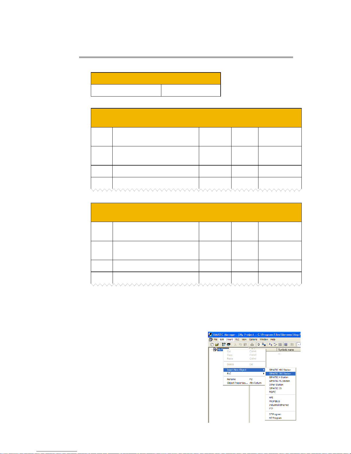
Prior knowledge of the SIMATIC 300 PLC and SIMATIC Manager
software is assumed. The following is an example of configuring the
PLC.
1. Create a project.
Start SIMATIC Manager and create
a new project. Right-click on the
project name at the top level and
from Insert New Object select
SIMATIC 300 Station.
www.comoso.com
Page 19
11
AC30 Profibus DP-V1 Option
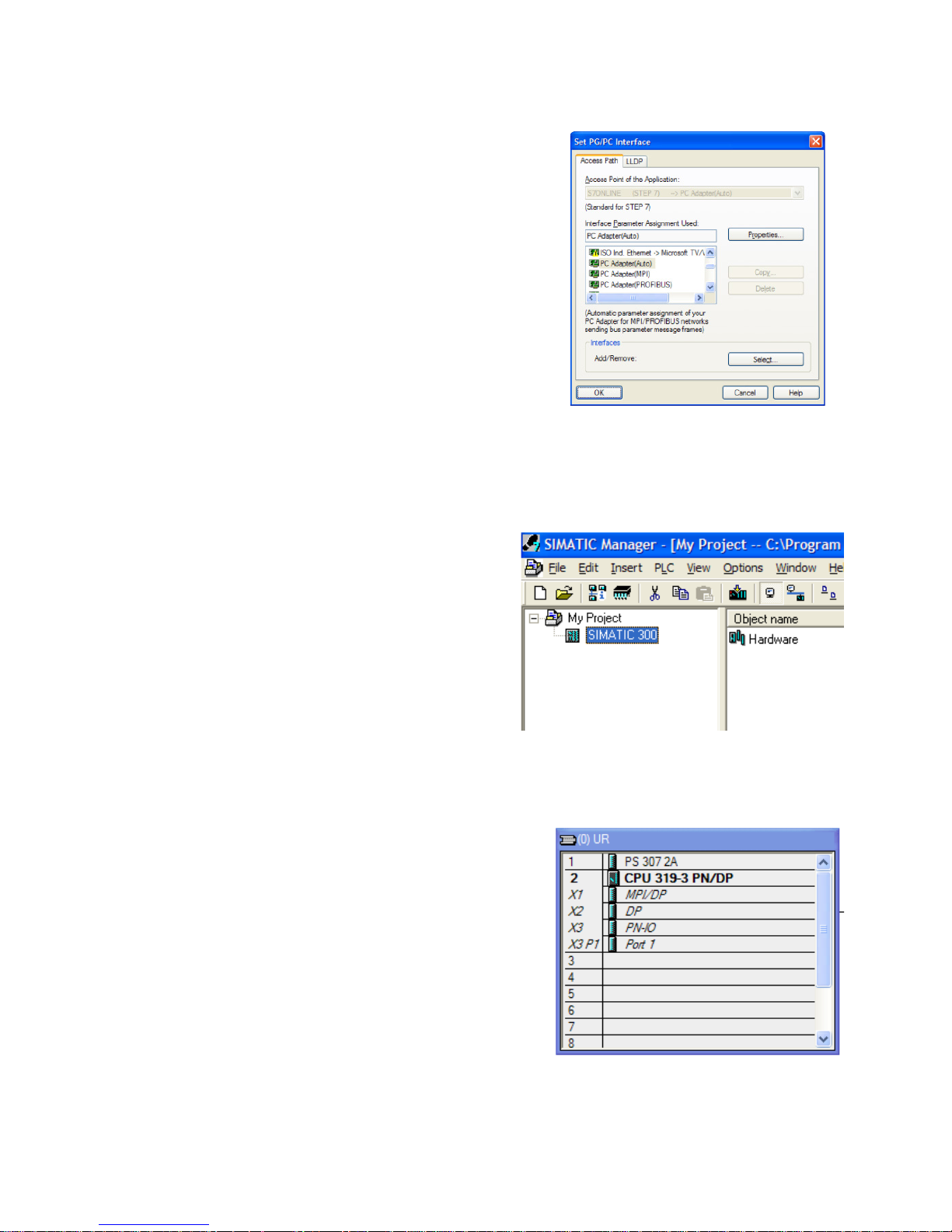
2. PLC Interface.
The interface between the PLC and
PC is selected by clicking on the
Options menu and choosing Set
PG/PC Interface.
In this example the PC Adapter is
chosen.
3. Start HW Config.
To configure the PLC, click on
SIMATIC 300 and double-click
on Hardware. This will start
HW Config.
4. Configure the PLC hardware.
In HW Config, select Insert from
the menu followed by Insert
Object. From the pop-up menu
choose SIMATIC 300
RACK
300
Rail. The rail should then
appear as shown.
Right-click on slot 1 to add the
appropriate power supply.
Right-click on slot 2 to add the appropriate CPU.
www.comoso.com
Page 20
12
AC30 Profibus DP-V1 Option
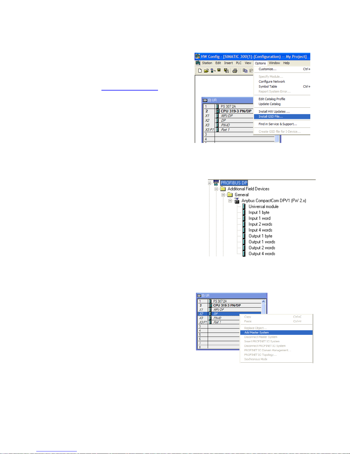
5. Install the GSD file.
Install the Profibus GSD file.
This can be downloaded from
www.parker.com/ssd
This will then become available in
the catalogue shown on the righthand side of the window under
PROFIBUS DP
Additional Field
Devices
General Anybus
CompactCom DPV1
6. Add the Profibus Controller.
Right-click on the Profibus (DP)
Controller module and select
Add Master System. Double
click on the Profibus: DP
master system to modify the
master node address, if
required.
www.comoso.com
Page 21
13
AC30 Profibus DP-V1 Option
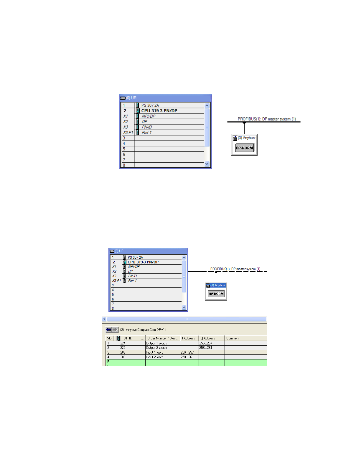
7. Add the slave.
Click and drag the Device from the catalogue and drop onto the
Profibus: DP master system. This represents the AC30 option
slave. When adding the slave device you can select its node address.
8. Configure the process data for the slave.
By selecting the slave, the input and output process data may be
configured. This must match the configuration set up in the AC30.
The appropriate input and output modules may be dragged from the
catalogue and dropped into the appropriate slot.
9. Save, compile and download.
Make sure the PC/PLC interface is connected. Select Station from
the menu and Save and Compile then select PLC and Download…
www.comoso.com
Page 22
14
AC30 Profibus DP-V1 Option
Configuring the AC30
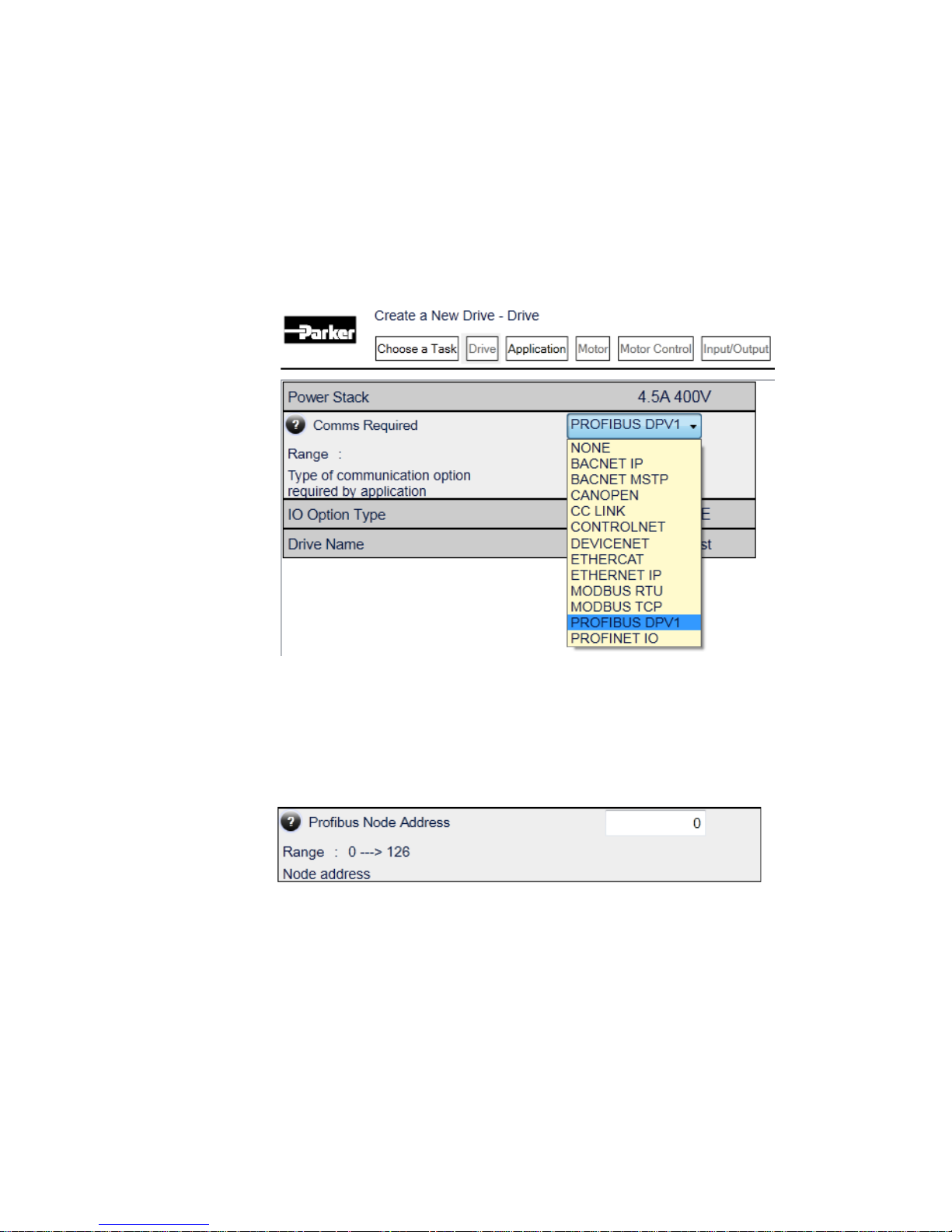
AC30 Parker Drive Quicktool (PDQ)
When performing an online configuration, the fitted option card will
automatically be selected. In offline mode, parameter 0044 Comms
required must be set to PROFIBUS DPV1:
Set the 0238 Profibus Node Address parameter to the required
address:
www.comoso.com
Page 23
15
AC30 Profibus DP-V1 Option
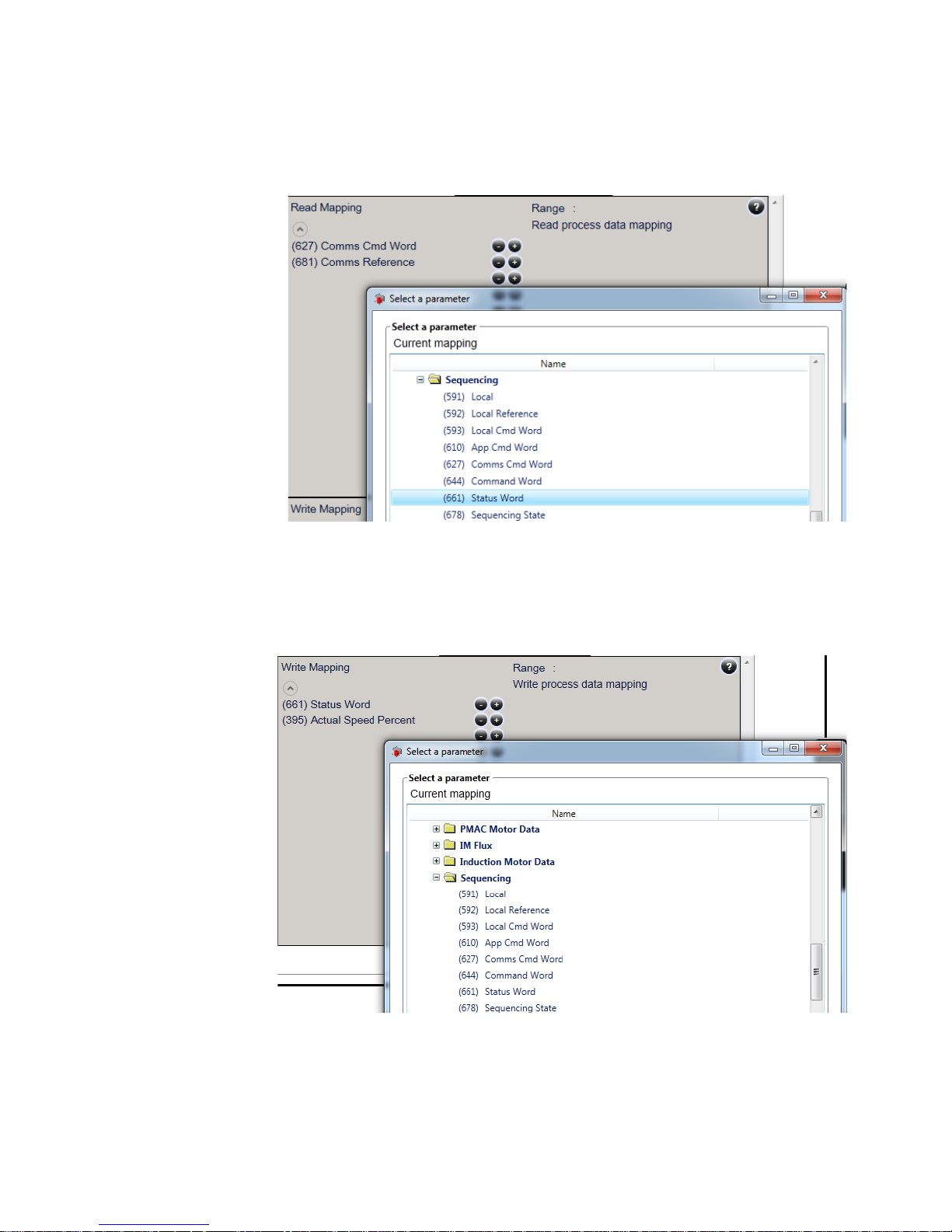
Add the required parameters to the Read Process Mapping table
(parameter 0055 Read Mapping) by selecting them from the popup
window:
Add the required parameters to the Write Process Mapping table
(parameter 0120 Write Mapping) by selecting them from the popup
window:
Note the Process Data mapping ends on the first empty entry.
www.comoso.com
Page 24

16
AC30 Profibus DP-V1 Option
Acyclic Data Exchange
AC30 parameters may be accessed acyclically from the network using
DP-V1 MS1/MS2 read / write services.
Overview
The AC30 parameters are mapped to slots and indexes as follows:
parameter number = slot * 255 + index + 1
slot = (parameter number – 1) / 255
index = (parameter number – 1 ) MODULO 255
• The Class 1 and Class 2 Request buffers are each 68 bytes.
• When reading more data than the actual size of the parameter,
the response will only contain the actual parameter data without
any additional padding.
• When reading less data than the actual size of the parameter, only
the requested amount of data is returned.
• Parameter arrays may be accessed; either as a whole or as
individual elements. See the Appendix A– Array Parameter
Numbers.
• Parameter string arrays must be accessed by each element.
Attempting to access the whole array will only return the first
element.
• The following relevant read / write error codes may be returned:
Error
Code 1
Error
Code 2
Error Type
Description
0xB0 0x04 Invalid index
Parameter number out of
range
0xB1
0x0A
Write error length
Too much data
0xB1
0x0B
Write error length
Not enough data
0xB6
0x08
Access denied
Parameter not writable
0xB6
0x09
Access denied
Parameter not readable
0xB7
0x0C
Invalid range
Value out of range
www.comoso.com
Page 25

17
AC30 Profibus DP-V1 Option
Parameter Read / Write with Call
The Parameter Read/Write with Call enables addressing of
parameters based on the parameter number rather than Slot and
Index. This uses a DP-V1 write service (function 5Fh) request
followed by a DP-V1 read service (function 5Eh) response. The read /
write service uses Slot 00h, Index FFh.
Parameter Read Call
The following service request translates to a request to read a
parameter:
Byte
#
Contents
Field
Value
1
DP-V1
Header
Function no. of write service
5Fh
2
Slot
00h
3
Index
FFh
4
Length of telegram
06h
5
Call
External function no.
08h
6
Reserved
00h
7
Sub-index (high)
00h
8
Sub-index (low)
02h
9
Parameter number (high byte)
0000h…
FFFFh
10
Parameter number (low byte)
The following service translates to the response:
Byte
#
Contents
Field
Value
1
DP-V1
Header
Function no. of read service
5Eh
2
Slot
00h
3
Index
FFh
4
Length of telegram
06h...F0h
5
Call
External function no.
08h
6
Reserved
00h
7
Sub-index (high)
00h
8
Sub-index (low)
02h
9
Parameter number (high byte)
0000h...
FFFFh
10
Parameter number (low byte)
11…n
Data
www.comoso.com
Page 26

18
AC30 Profibus DP-V1 Option
Parameter Write Call
The following service request translates to a request to write to a
parameter:
Byte
#
Contents
Field
Value
1
DP-V1
Header
Function no. of write service
5Fh
2
Slot
00h
3
Index
FFh
4
Length of telegram
06h…F0h
5
Call
External function no.
08h
6
Reserved
00h
7
Sub-index (high)
00h
8
Sub-index (low)
01h
9
Parameter number (high byte)
0000h…
FFFFh
10
Parameter number (low byte)
11…n
Data
The following service translates to the response:
Byte
#
Contents
Field
Value
1
DP-V1
Header
Function no. of read service
5Eh
2
Slot
00h
3
Index
FFh
4
Length of telegram
06h
5
Call
External function no.
08h
6
Reserved
00h
7
Sub-index (high)
00h
8
Sub-index (low)
01h
9
Parameter number (high byte)
0000h...
FFFFh
10
Parameter number (low byte)
www.comoso.com
Page 27
19
AC30 Profibus DP-V1 Option
Example Acyclic Data Exchange
Example using a SIMATIC PLC
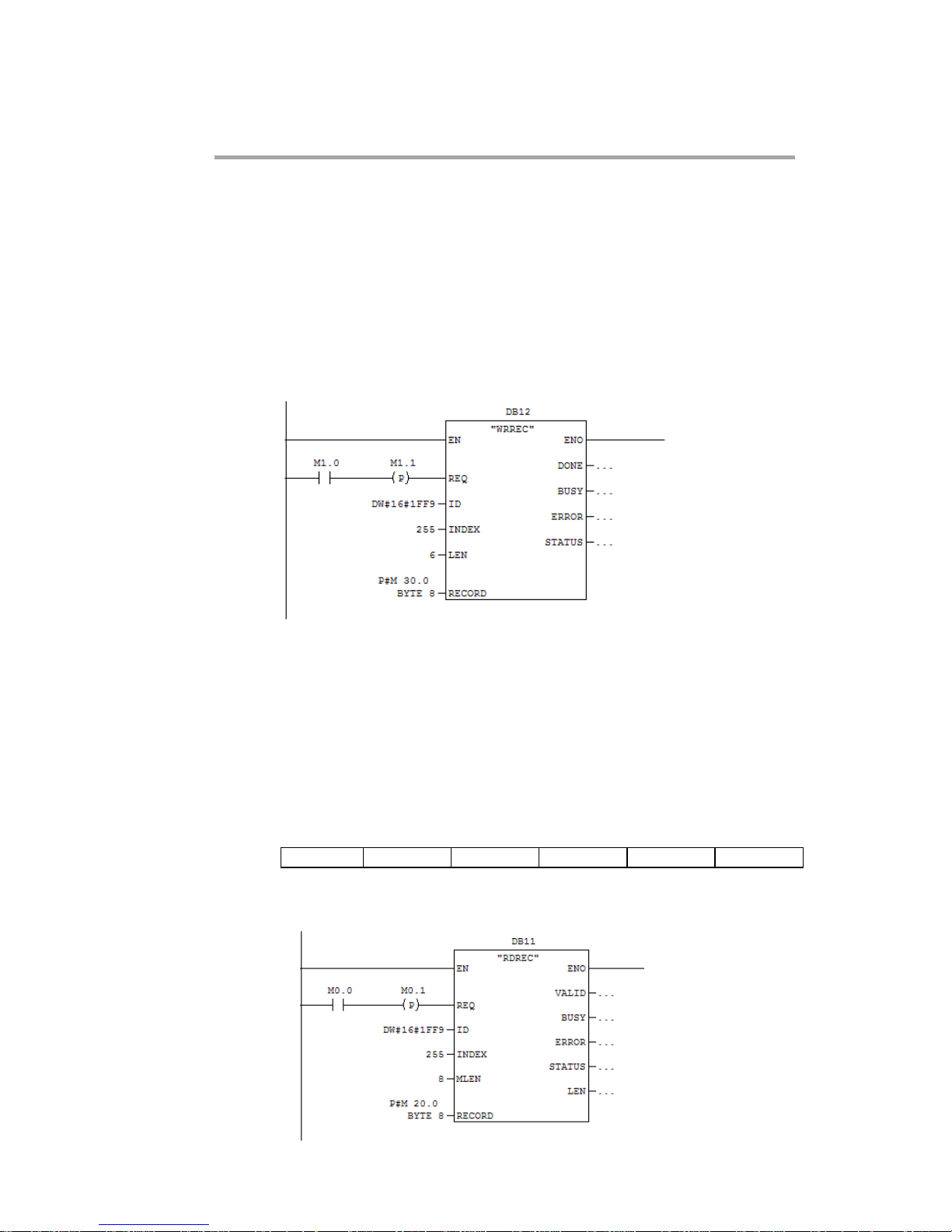
The DP-V1 read and write services may be achieved using the
functions SFB52 RDREC and SFB53 WRREC.
In this example a parameter of length 2 bytes will be read using the
Parameter Read Call.
First, using the WRREC, the parameter number is passed, as shown
below.
The INDEX is set to 255 as required by the Call. The ID in this case is
set to 1FF9h (8185) which is the diagnostic address found in Slot 0.
LEN sets the required length of the telegram.
The call request is sent is pointed to by the RECORD parameter. This
record will contain the request telegram as given in the previous
section, with the last two bytes representing the parameter number, in
this case 563 (0233h).
The data from parameter 563 can then be read using the RDREC.
08h
00h
00h
02h
02h
33h
www.comoso.com
Page 28

20
AC30 Profibus DP-V1 Option
The RECORD parameter will hold the response telegram, the length
of which will be 8 bytes which includes the two bytes of the read
parameter data. The expected response would be as shown below
with the last two bytes representing the parameter data.
08h
00h
00h
02h
02h
33h
data
data
www.comoso.com
Page 29

21
AC30 Profibus DP-V1 Option
Lost Communications Trip
Supervised Parameter
The 0047 Comms Supervised parameter indicates that the Profibus
network participation is supervised by another Profibus device.
The Supervised parameter value is set to TRUE when either:
• The Parameterisation and configuration data have been
accepted (MS0 connection established)
• An MS2 connection is open
The Supervised parameter will subsequently change to FALSE if the
connection is closed or the Profibus watchdog (if enabled) has timed
out.
Comms Break Trip
The Comms Break trip will generate a trip if a break in
communications is detected. A trip event will be generated when a
transition from TRUE to FALSE of the parameter 0047 Comms
Supervised occurs.
To enable the Comms Break trip, the parameter 0048 Comms Trip
Enable must be set to TRUE and the COMMS BREAK bit set in the
parameter 0697 Enable 1-32.
For more information on enabling trips see Chapter 10 Trips & Fault
Finding in the AC30 Product Manual HA501718U001.
www.comoso.com
Page 30

22
AC30 Profibus DP-V1 Option
Diagnostic Event
A single diagnostic event may be created. This adds a status PDU to
the Extended Diagnostics. The severity is fixed as Minor
Recoverable.
Four AC30 parameters are associated with the diagnostic event:
0185 Comms Event Code
This code will be used in the status PDU in the diagnostics. This
corresponds to the status diagnostic message in the GSD file. For
example, code 0x10 represents “Generic Error”.
0187 Comms Event Set
A rising edge signal from FALSE to TRUE will create a diagnostic
event. The Comms Event Clear parameter must be set FALSE.
0188 Comms Event Clear
A rising edge signal from FALSE to TRUE will remove a diagnostic
event. The Comms Event Set parameter must be set to FALSE.
0186 Comms Event Active
This parameter indicates if a diagnostic event is active or not.
Note: The rising edge signals for Comms Event Set and Comms
Event Clear must be held for at least 10ms in FALSE and at least
10ms in TRUE to take effect.
When a diagnostic event is active the Status LED will flash green.
www.comoso.com
Page 31
23
AC30 Profibus DP-V1 Option
Parameters
Configuration Parameters
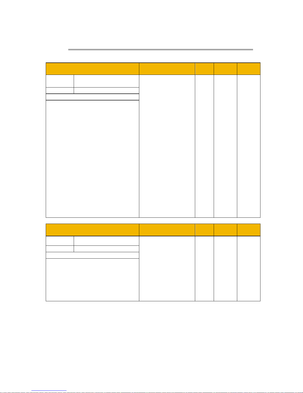
0044 Comms Required
Range RW Saved Config
Type
USINT
(enumerated)
(1) NONE
(2) BACNET IP
(3) BACNET
MSTP
(4) CANOPEN
(5) CC LINK
(6) CONTROLNET
(7) DEVICENET
(8) ETHERCAT
(9) ETHERNET IP
(10) MODBUS RTU
(11) MODBUS TCP
(12) PROFIBUS
DPV1
(13) PROFINET IO
Default
NOT FITTED
Communications option parameter.
Sets the required communications
option.
0238 Profibus Node Address
Range RW Saved Config
Type USINT
0
…
126
Default
0
Profibus communications option
parameter.
Sets the required node address.
If set to 126 then the SSA (Set Slave
Address) will be used.
www.comoso.com
Page 32
24
AC30 Profibus DP-V1 Option
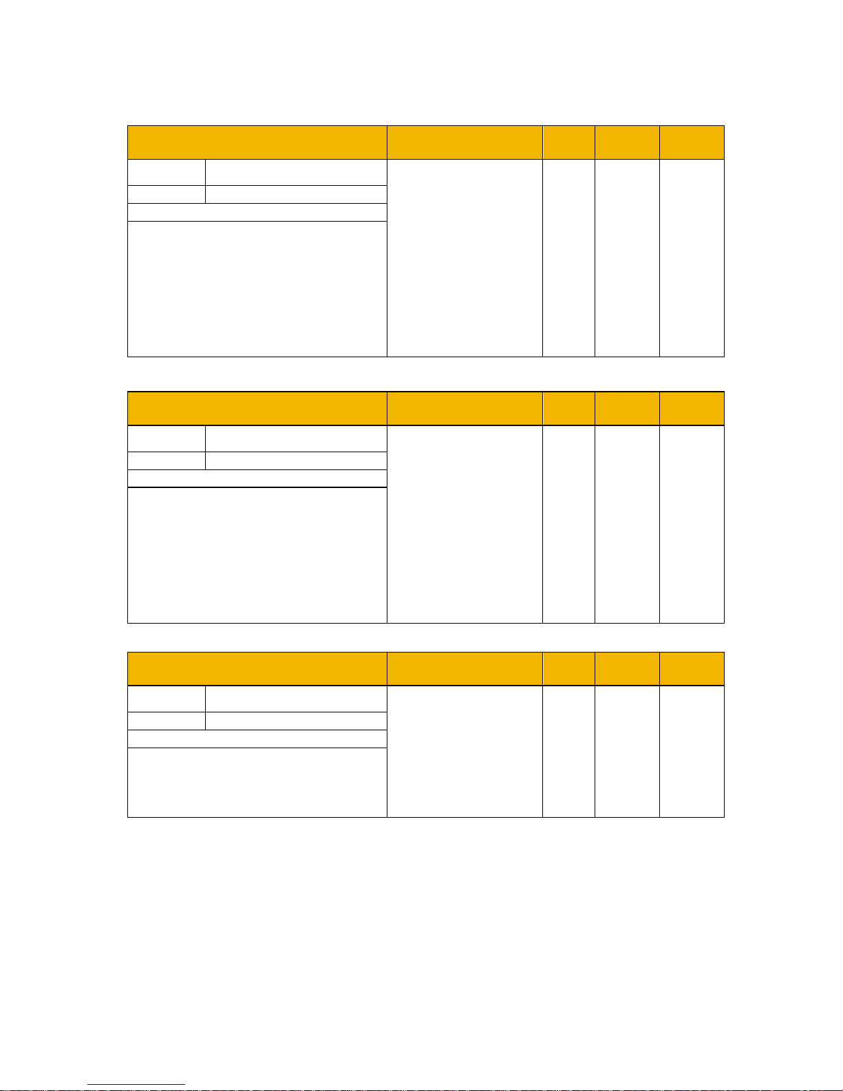
0055 Read Mapping
Range RW Saved Config
Type Array of UINT
0
…
Last parameter
number
Default
0
Communications option parameter.
Sets the required read process data
mapping.
Each entry in the table represents
the required parameter number.
0120 Write Mapping
Range RW Saved Config
Type Array of UINT
0
…
Last parameter
number
Default
0
Communications option parameter.
Sets the required write process data
mapping.
Each entry in the table represents
the required parameter number.
0048 Comms Trip Enable
Range RW Saved Config
Type BOOL
FALSE
TRUE
Default
FALSE
Communications option parameter.
Enables the communications trip.
www.comoso.com
Page 33

25
AC30 Profibus DP-V1 Option
Runtime Parameters
0185 Comms Event Code
Range RW Saved Config
Type BYTE
0x00
…
0xFF
Default
0
Communications option parameter.
Sets the event code to be used
when a diagnostic event is created.
0187 Comms Event Set
Range RW Saved Config
Type BOOL
FALSE
TRUE
Default
FALSE
Communications option parameter.
A rising edge (FALSE to TRUE) will
create a diagnostic event.
0188 Comms Event Clear
Range RW Saved Config
Type BOOL
FALSE
TRUE
Default
TRUE
Communications option parameter.
A rising edge (FALSE to TRUE) will
remove a diagnostic event.
www.comoso.com
Page 34

26
AC30 Profibus DP-V1 Option
Diagnostic Parameters
0045 Comms Fitted
Range
Type
USINT
(enumerated)
(0) UNKNOWN
(1) NONE
(2) BACNET IP
(3) BACNET MSTP
(4) CANOPEN
(5) CC LINK
(6) CONTROLNET
(7) DEVICENET
(8) ETHERCAT
(9) ETHERNET IP
(10) MODBUS RTU
(11) MODBUS TCP
(12) PROFIBUS DPV1
(13) PROFINET IO
Communications option parameter.
Indicates the communications option
fitted.
0046 Comms State
Range
Type
USINT
(enumerated)
(0) SETUP – setup in progress
(1) NW INIT – network-related initialisation
tasks are being performed
(2) WAIT PROCESS – no MS0 connection
(3) IDLE – MS0 established / MS2 connection
may be open (master mode = clear)
(4) PROCESS ACTIVE– MS0 established /
MS2 connection may be open (master
mode = operate)
(5) ERROR – network error
(6) RESERVED
(7) EXCEPTION – unrecoverable error
(8) NONE – option not fitted
Communications option parameter.
Indicates the state of the
communications option fitted.
www.comoso.com
Page 35
27
AC30 Profibus DP-V1 Option
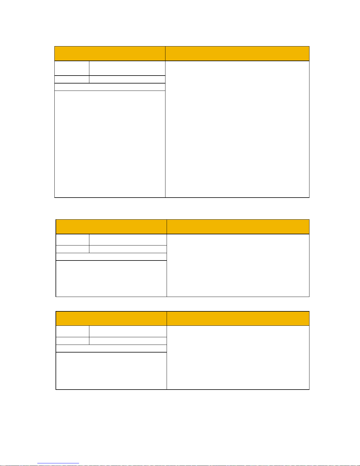
0237 Profibus State
Range
Type
USINT
(enumerated)
(0) SETUP – setup in progress
(1) NW INIT – network-related initialisation
tasks are being performed
(2) WAIT PROCESS – no MS0 connection
(3) IDLE – MS0 established / MS2 connection
may be open (master mode = clear)
(4) PROCESS ACTIVE– MS0 established /
MS2 connection may be open (master
mode = operate)
(5) ERROR – network error
(6) RESERVED
(7) EXCEPTION – unrecoverable error
(8) NONE – option not fitted
Profibus communications option
parameter.
Indicates the state of the
communications option fitted as the
parameter 0046 Comms State, but
specifically for Profibus.
0047 Comms Supervised
Range
Type BOOL
FALSE
TRUE
Communications option parameter.
Indicates that the Profibus network
participation is supervised by
another Profibus device.
0049 Comms Module Version
Range
Type DWORD
0x00000000
…
0xFFFFFFFF
The most significant byte is the major version
number, followed by the minor version number.
The least significant byte is the build number.
Communications option parameter.
Firmware version of the option
communications module.
www.comoso.com
Page 36
28
AC30 Profibus DP-V1 Option
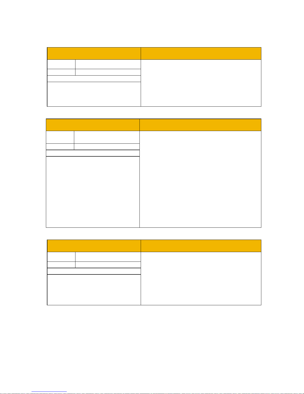
0050 Comms Module Serial
Range
Type DWORD
0x00000000
…
0xFFFFFFFF
Communications option parameter.
Serial number of the option
communications module.
0051 Comms Diagnostic
Range
Type
USINT
(enumerated)
(0) NONE
(1) HARDWARE MISMATCH – required
communications option does not match that
fitted, or no option fitted but one is required.
(2) INVALID CONFIGURATION – the
configuration of the option is not valid.
(3) MAPPING FAILED – the process data
mapping is not permitted, e.g. adding readonly parameters to the read process data
mapping.
(4) EXCEPTION – configuration error
(5) UNSUPPORTED OPTION – the fitted
option is not currently supported
Communications option parameter.
Indicates the state of the
communications option fitted.
0052 Comms Diagnostic Code
Range
Type DWORD
0x00000000
…
0xFFFFFFFF
Communications option parameter.
Diagnostic code associated with the
Diagnostic parameter.
www.comoso.com
Page 37

29
AC30 Profibus DP-V1 Option
0053 Comms Exception
Range
Type BYTE
0x00
…
0xFF
Communications option parameter.
Exception code associated with the
Diagnostic parameter being in
EXCEPTION
0054 Comms Net Exception
Range
Type BYTE
0x00
…
0xFF
Communications option parameter.
Network specific exception code
associated with the Diagnostic
parameter being in EXCEPTION
0186 Comms Event Active
Range
Type BOOL
FALSE
TRUE
Communications option parameter.
Indicates a diagnostic event is
active.
www.comoso.com
Page 38

30
AC30 Profibus DP-V1 Option
Troubleshooting
Configuration problems can often be identified by looking at the
Operation Mode and Status LEDs and from the Profibus State and
Comms Diagnostic parameters. Under normal operating conditions
the parameter Comms Diagnostic should indicate NONE. Other
values are summarized in the Diagnostic Parameters section.
Hardware Mismatch
Diagnostic = HARDWARE MISMATCH
• The required option does not match the actual fitted option.
• No option is fitted but one is required.
Invalid Configuration
Diagnostic = INVALID CONFIGURATION
• Invalid read or write process data mapping
• No read or write process data mapped
• Invalid communication settings
Diagnostic = MAPPING FAILED
• Attempting to map a parameter that does not exist.
• Attempting to map a configuration parameter.
• Attempting to map a string parameter.
• Attempting to map a read-only parameter to the read
process data.
Diagnostic = INVALID CONFIGURATION and Status LED Red and
Exception = 0x06 and
Net Exception = 0x04
• Process data mapping exceeds total size of 152 bytes
Operation LED Flashing Red (2 flashes)
• The AC30 configuration and mapping does not match that
of the PLC.
PLC Indication
Flashing Bus Fault (BF) LED on the PLC.
• A module in the hardware configuration (HW Config) does
not match the physical module or that the module is not
connected to the network.
www.comoso.com
Page 39
31
AC30 Profibus DP-V1 Option
Appendix A – Array Parameter Numbers
Some parameters have multiple elements and are classified as
parameter arrays. A parameter array has a parameter number that
accesses the whole of the array. It also has parameter numbers that
represent each element of the array.
Array Example
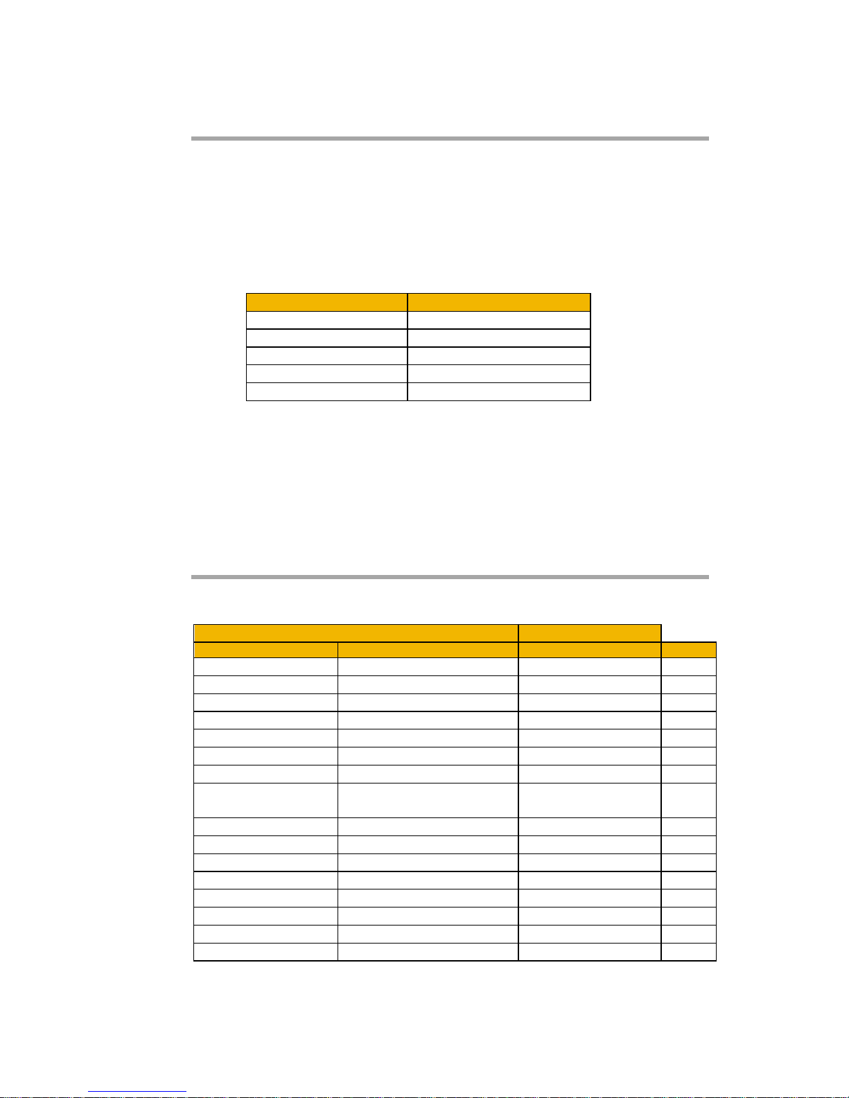
A parameter array called My Array has 4 elements.
Parameter Number
Parameter - My Array
0152
Whole array
0153
index 0
0154
index 1
0155
index 2
0156
index 3
If the parameter number of the whole array is 0152, then the
parameter number of the element index 0 of the array will be 0153,
the parameter number of the element index 01 will be 0154, etc.
Note that string array parameters access their elements via parameter
numbers that are calculated in a different way. See the AC30 Product
Manual HA501718U001 for more details.
Appendix B – Data Types
The relationship between AC30 parameter and Profibus data type is
given in the table below.
AC30 Parameter
Profibus
Data Type
Description
Data Type
Bytes
BOOL
Boolean
Boolean
1
SINT
Short integer
Integer8
1
INT
Integer
Integer16
2
DINT
Double integer
Integer32
4
USINT
Unsigned short integer
Unsigned8
1
UINT
Unsigned integer
Unsigned16
2
UDINT
Unsigned double integer
Unsigned32
4
REAL
Floating point
Floating Point
(32-bit IEEE-754)
4
TIME
Duration
Unsigned32
4
DATE
Date
Unsigned32
4
TIME_OF_DAY
Time of day
Unsigned32
4
DATE_AND_TIME
Date and time of day
Unsigned32
4
STRING
String
Visible string
n
BYTE
Bit string length 8
Unsigned8
1
WORD
Bit string length 16
Unsigned16
2
DWORD
Bit string length 32
Unsigned32
4
www.comoso.com
Page 40

Parker Hannifi n Manufacturing Limited,
Automation Group, SSD Drives Europe,
New Courtwick Lane, Littlehampton,
West Sussex BN17 7RZ
United Kingdom
Tel: +44(0)1903 737000
Fax: +44(0)1903 737100
www.parker.com/ssd
*HA501837U001_01*
AE – UAE, Dubai
Tel: +971 4 8127100
[email protected]
AR – Argentina, Buenos Aires
Tel: +54 3327 44 4129
AT – Austria, Wiener Neustadt
Tel: +43 (0)2622 23501-0
[email protected]
AT – Eastern Europe,
Wiener Neustadt
Tel: +43 (0)2622 23501 900
[email protected]
AU – Australia, Castle Hill
Tel: +61 (0)2-9634 7777
AZ – Azerbaijan, Baku
Tel: +994 50 2233 458
[email protected]
BE/LU – Belgium, Nivelles
Tel: +32 (0)67 280 900
[email protected]
BR – Brazil, Cachoeirinha RS
Tel: +55 51 3470 9144
BY – Belarus, Minsk
Tel: +375 17 209 9399
[email protected]
CA – Canada, Milton, Ontario
Tel: +1 905 693 3000
CH – Switzerland, Etoy
Tel: +41 (0)21 821 87 00
[email protected]
CL – Chile, Santiago
Tel: +56 2 623 1216
CN – China, Shanghai
Tel: +86 21 2899 5000
CZ – Czech Republic, Klecany
Tel: +420 284 083 111
[email protected]
DE – Germany, Kaarst
Tel: +49 (0)2131 4016 0
[email protected]
DK – Denmark, Ballerup
Tel: +45 43 56 04 00
[email protected]
ES – Spain, Madrid
Tel: +34 902 330 001
[email protected]
FI – Finlan d, Vanta a
Tel: +358 (0)20 753 2500
parker. [email protected]
FR – France, Contamine s/Arve
Tel: +33 (0)4 50 25 80 25
[email protected]
GR – Greece, Athens
Tel: +30 210 933 6450
[email protected]
HK – Hong Kong
Tel: +852 2428 8008
HU – Hungary, Budapest
Tel: +36 1 220 4155
[email protected]
IE – Ireland, Dublin
Tel: +353 (0)1 466 6370
[email protected]
IN – India, Mumbai
Tel: +91 22 6513 7081-85
IT – Italy, Corsico (MI)
Tel: +39 02 45 19 21
[email protected]
JP – Japan, Tok yo
Tel: +81 (0)3 6408 3901
KR – South Korea, Seoul
Tel: +82 2 559 0400
KZ – Kazakhstan, Almaty
Tel: +7 7272 505 800
[email protected]
MX – Mexico, Apodaca
Tel: +52 81 8156 6000
MY – Malaysia, Shah Alam
Tel: +60 3 7849 0800
NL – The Netherlan ds,
Oldenzaal
Tel: +31 (0)541 585 000
[email protected]
NO – Norway, Asker
Tel: +47 66 75 34 00
[email protected]
NZ – New Zealand, Mt Wellington
Tel: +64 9 574 1744
PL – Poland, Warsaw
Tel: +48 (0)22 573 24 00
[email protected]
PT – Por tugal,
Leca da Palmeira
Tel: +351 22 999 7360
[email protected]
RO – Romania, Bucharest
Tel: +40 21 252 1382
[email protected]
RU – Rus sia, Moscow
Tel: +7 495 645-2156
[email protected]
SE – Sweden, Spånga
Tel: +46 (0)8 59 79 50 00
[email protected]
SG – Singapore
Tel: +65 6887 6300
SK – Slovakia, Banská Bystrica
Tel: +421 484 162 252
[email protected]
SL – Slovenia, Novo Mesto
Tel: +386 7 337 6650
[email protected]
TH – Thailand, Bangkok
Tel: +662 717 8140
TR – Turkey, Istanbul
Tel: +90 216 4997081
[email protected]
TW – Taiwan, Ta ipe i
Tel: +886 2 2298 8987
UA – Ukraine, Kiev
Tel +380 44 494 2731
[email protected]
UK – United Kingdom,
Warwick
Tel: +44 (0)1926 317 878
[email protected]
US – USA, Cleveland
Tel: +1 216 896 3000
VE – Venezuela, Caracas
Tel: +58 212 238 5422
ZA – South Africa,
Kempton Park
Tel: +27 (0)11 961 0700
[email protected]
© 2012 Parker Hanni n Corporation. All rights reserved.
Parker Worldwide
European Product Information Centre
Free phone: 00 8 00 27 27 5374
(from AT, BE, CH, CZ, DE, EE , ES, FI, FR, IE,
IL, IS, IT, LU, MT, NL , NO, PT, SE, SK, UK)
www.comoso.com
 Loading...