

Page 1
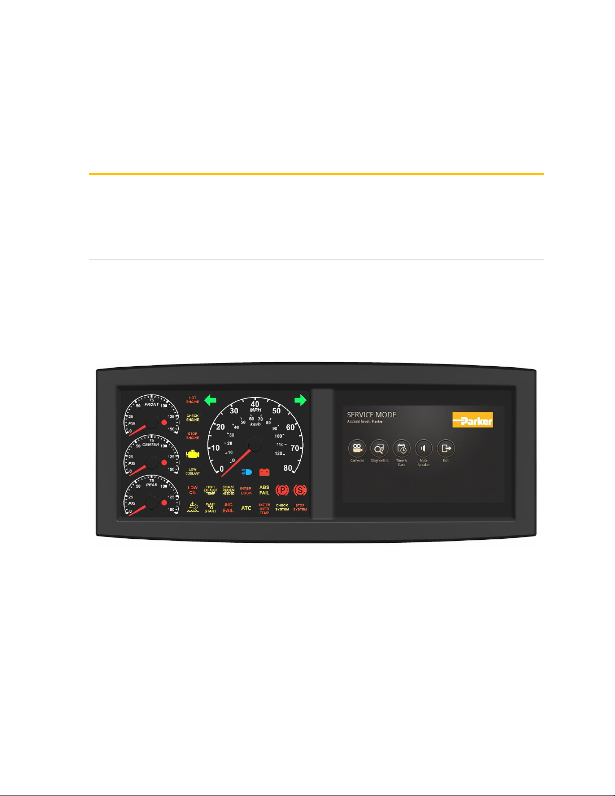
Display Panel Standard
DPS70
With 7” touchscreen
U s e r G uid e
UG-DPS70-1020000-201906-003
Page 2

Parker Hannifin Canada
Electronic Controls Division
1305 Clarence Avenue
Winnipeg, MB R3T 1T4 Canada
office +1 204 452 6776
Fax +1 204 478 1749
http://www.parker.com/ecd
Copyright 2019 © Parker Hannifin Corporation. All rights reserved. No part of this work may be
reproduced, published, or distributed in any form or by any means (electronically, mechanically,
photocopying, recording, or otherwise), or stored in a database retrieval system, without the prior
written permission of Parker Hannifin Corporation in each instance.
Warning!
FAILURE OR IMPROPER SELECTION OR IMPROPER USE OF THE PRODUCTS AND/OR SYSTEMS
DESCRIBED HEREIN OR RELATED ITEMS CAN CAUSE DEATH, PERSONAL INJURY AND PROPERTY
DAMAGE.
• This document and other information from Parker Hannifin Corporation, its subsidiaries and authorized
distributors provide product and/or system options for further investigation by users having technical expertise.
• The user, through its own analysis and testing, is solely responsible for making the final selection of the
system and components and assuring that all performance, endurance, maintenance, safety and warning
requirements of the application are met. The user must analyze all aspects of the application, follow applicable
industry standards, and follow the information concerning the product in the current product catalog and in any
other materials provided from Parker or its subsidiaries or authorized distributors.
• To the extent that Parker or its subsidiaries or authorized distributors provide component or system options
based upon data or specifications provided by the user, the user is responsible for determining that such data
and specifications are suitable and sufficient for all applications and reasonably foreseeable uses of the
components or systems.
• The Buyer and/or end-user will be solely responsible for final disposal of all products.
Offer of Sale
The items described in this document are hereby offered for sale by Parker Hannifin Corporation, its subsidiaries
or its authorized distributors. This offer and its acceptance are governed by the provisions stated in the "Offer of
Sale" elsewhere in this document, or available at www.parker.com.
Page 3

User Guide iii
Publication History ............................................................................................................... v
Safety .................................................................................................................................... vi
Safety symbols ................................................................................................................................. vi
General safety regulations ............................................................................................................... vi
Welding after installation ................................................................................................................. vii
Construction regulations ................................................................................................................. vii
Safety during installation ................................................................................................................. vii
Safety during start-up ..................................................................................................................... viii
Safety during maintenance and fault diagnosis ............................................................................. viii
1. About the DPS70 ............................................................................................................... 1
1.1. Diagram conventions ................................................................................................................ 4
1.2. Regulatory Requirements ......................................................................................................... 5
1.2.1. Regulatory Compliance ............................................................................................... 5
1.2.2. Declaration of Regulatory Compliance ........................................................................ 5
2. Inputs ................................................................................................................................. 6
2.1. Analog Inputs ............................................................................................................................ 6
2.1.1. Analog Input Capabilities ............................................................................................. 6
2.1.2. Analog Input Configuration Options ............................................................................ 7
2.1.3. Analog Input Installation Connections ......................................................................... 7
2.2. DPS70 Frequency Inputs .......................................................................................................... 7
2.2.1. DPS70 Frequency Input Capabilities .......................................................................... 8
2.2.2. DPS70 Frequency Input Installation Connections ....................................................... 8
2.3. Digital Inputs ............................................................................................................................. 9
2.3.1. DPS70 Digital Input Capabilities.................................................................................. 9
2.3.2. Digital Input Installation Connections ........................................................................ 10
2.4. Video Inputs ............................................................................................................................ 11
2.4.1. Video Input Capabilities ............................................................................................. 11
3. Outputs ............................................................................................................................ 12
3.1. High-Side Outputs ................................................................................................................... 12
3.1.1. High-Side Output Capabilities ................................................................................... 12
3.1.2. High-Side Output Configuration Options ................................................................... 13
3.1.3. High-Side Output Installation Connections ................................................................ 13
3.1.4. High-Side Output Diagnostics and Fault Detection ................................................... 14
3.2. Sensor Supply Output ............................................................................................................. 16
3.2.1. Sensor Supply Output Capabilities ............................................................................ 16
Contents
Page 4

iv DPS70
Contents
3.2.2. Sensor Supply Output Installation Connections ........................................................ 16
3.2.3. Sensor Supply Output Diagnostics and Fault Detection ............................................ 16
4. Power ............................................................................................................................... 17
5. Communication ............................................................................................................... 18
5.1. CAN ......................................................................................................................................... 18
5.2. USB Host ................................................................................................................................. 18
5.3. USB Device ............................................................................................................................. 19
5.4. RS232 ...................................................................................................................................... 19
5.5. Ethernet ................................................................................................................................... 19
6. Display ............................................................................................................................. 20
7. Gauge Area ...................................................................................................................... 22
7.1. Status Indicator LEDs .............................................................................................................. 22
7.2. Analog Gauges ........................................................................................................................ 23
7.2.1. Gauge Backlighting .................................................................................................... 23
7.3. Buzzer ...................................................................................................................................... 24
7.4. Real Time Clock ...................................................................................................................... 24
8. Connectors ...................................................................................................................... 25
8.1. Pinouts ..................................................................................................................................... 26
9. Mounting .......................................................................................................................... 28
9.1. Mechanical requirements ........................................................................................................ 28
9.2. Dimensions .............................................................................................................................. 29
10. Environmental Protection ............................................................................................ 30
11. Glossary ......................................................................................................................... 31
12. Index ............................................................................................................................... 42
Page 5
User Guide v
The following table provides an overview of the changes made to this document
over the course of its publication history.
Release Date
Description of Change
Rev. 001
First release of this document, February 2014
Rev. 002
Minor edits from User Guide review meeting, 2014-02-25 and 2014-03-03
Rev. 003
Remove 3rd CAN bus (not implemented), 2019-06-05
Publication History
Page 6

User Guide vi
Do not perform the procedures in this manual unless you are experienced in the
handling of electronic equipment.
Contact the manufacturer if there is anything you are not sure about or if you have
any questions regarding the product and its handling or maintenance.
The term "manufacturer" refers to Parker Hannifin Corporation.
Safety symbols
The following symbols are used in this document to indicate potentially
hazardous situations:
Danger! Risk of death or injury.
Warning! Risk of damage to equipment or degradation of signal
When you see these symbols, follow the instructions carefully and proceed with
caution.
General safety regulations
Work on the hydraulics control electronics may only be carried out by trained
personnel who are well-acquainted with the control system, the machine, and its
safety regulations.
Follow the manufacturer's regulations when mounting, modifying,
repairing, and maintaining equipment. The manufacturer assumes no
responsibility for any accidents caused by incorrectly mounted or
incorrectly maintained equipment. The manufacturer assumes no
responsibility for the system being incorrectly applied, or the system
being programmed in a manner that jeopardizes safety.
Safety
Page 7

User Guide vii
Safety
Do not use the product if electronic modules, cabling, or connectors are
damaged or if the control system shows error functions.
Electronic control systems in an inappropriate installation and in
combination with strong electromagnetic interference fields can, in
extreme cases, cause an unintentional change of speed of the output
function.
Welding after installation
Complete as much as possible of the welding work on the chassis before the
installation of the system. If welding has to be done afterwards, proceed as
follows:
Do not place the welding unit cables near the electrical wires of the
control system.
1. Disconnect the electrical connections between the system and external
equipment.
2. Disconnect the negative cable from the battery.
3. Disconnect the positive cable from the battery.
4. Connect the welder's ground wire as close as possible to the place of the
welding.
Construction regulations
The vehicle must be equipped with an emergency stop which disconnects the
supply voltage to the control system's electrical units. The emergency stop must
be easily accessible to the operator. If possible, the machine must be built so that
the supply voltage to the control system's electrical units is disconnected when the
operator leaves the operator’s station.
Safety during installation
Incorrectly positioned or mounted cabling can be influenced by radio
signals, which can interfere with the functions of the system.
Page 8

viii DPS70
Safety
Safety during start-up
Danger! Risk of death or injury. Do not start the machine's engine
before the control system is mounted and its electrical functions have
been verified.
Do not start the machine if anyone is near the machine.
Safety during maintenance and fault diagnosis
Before performing any work on the hydraulics control electronics, ensure that
▪ The machine cannot start moving.
▪ Functions are positioned safely.
▪ The machine is turned off.
▪ The hydraulic system is relieved from any pressure.
▪ Supply voltage to the control electronics is disconnected.
Page 9
User Guide 1
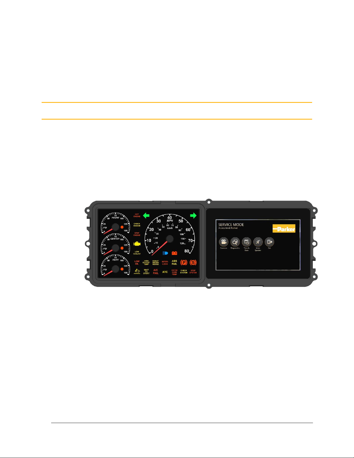
The DPS70 product is a display cluster that has a 7" touch screen, 4 analog gauges
and 26 indicator lights. The product is provided with a Linux operating system.
The product includes five NTSC/PAL D1 video inputs for display of vehicle
cameras. Four of the video inputs can be simultaneously viewed on the display.
The fifth input is recommended to be dedicated for the backup camera.
The communication options to the cluster are USB host, USB device, RS232,
10/100 Ethernet and 2 CAN buses.
Figure 1: DPS70 display cluster
The DPS70 is controlled by software. Contact your Parker Vansco Account
Representative for more details about the programming tools.
1. About the DPS70
Page 10

2 DPS70
About the DPS70
The DPS70 has 26 LEDs that are used as status indicators:
▪ 6 RGB tricolor with feed back
▪ 6 RGB tricolor
▪ 2 green
▪ 2 amber
▪ 6 red
▪ 1 blue
▪ 3 red gauge warnings.
The locations of the colors are fixed. The overlay can be configured by the
customer. Contact your Parker Vansco Account Representative for more details.
The DPS70 has 4 gauges and a large 7" (800x480) TFT LCD, IPS.
The DPS70 has a buzzer that is intended to be used typically for a fault alarm but
could also be used for other sounds.
The DPS70 can monitor up to 26 inputs:
▪ 10 analog inputs.
▪ 2 frequency inputs.
▪ 9 digital inputs (3 have option to be populated as wake-up/power control).
▪ 5 video inputs.
The DPS70 has 2 outputs:
▪ 2 high-side outputs.
The DPS70 has a sensor supply output:
▪ 1 sensor supply output (5 V, 100 mA).
The DPS70 can detect the following faults on the outputs:
▪ Short-circuit
▪ Overcurrent
▪ Open load
The DPS70 has 10 connectors:
▪ 2 x 20-pin Molex connectors that are used to interface with the inputs,
outputs, and CAN.
▪ 1 USB host type A.
▪ 1 USB device type B.
▪ 1 Ethernet RJ45
▪ 5 BNC for video inputs
Page 11

User Guide 3
About the DPS70
This manual describes the hardware components of the DPS70 but does not
explain how to write or configure the software. For more information about
software, refer to the appropriate software manual or contact your Parker Vansco
Account Representative.
Page 12
4 DPS70
About the DPS70
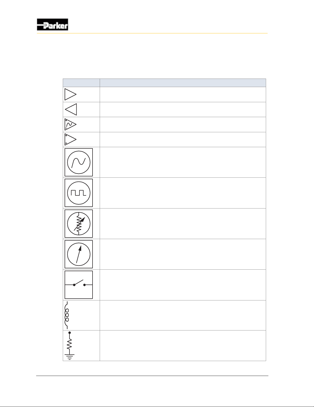
1.1. Diagram conventions
The following symbols are used in the schematic diagrams in this document:
Symbol
Meaning
General input
General output
Frequency input
Analog input
Frequency sensor
Pulse sensor
Resistive sensor
General sensor
Application switch
Load
Pull-down resistor
Page 13

User Guide 5
About the DPS70
Symbol
Meaning
Pull-up resistor
Battery
Fuse
Resistor
Ground
Chassis ground
1.2. Regulatory Requirements
The following sections summarize the regulatory requirements to be met by the
DPS70.
1.2.1. Regulatory Compliance
This product will be regulatory compliant to the following:
▪ Restriction of Hazardous Substances (RoHS) Compliant to Directive
2002/95/EC
▪ Waste Electrical and Electronic Equipment (WEEE) Compliant to Directive
2002/96/EC
1.2.2. Declaration of Regulatory Compliance
The product will be declared RoHS Compliant to IPC-1752 Class 1.
Page 14
6 DPS70
Inputs
The DPS70 has digital, frequency, and analog inputs.
Damage to equipment! Do not connect inputs directly to unprotected
inductive loads such as solenoids or relay coils, as these can produce
high voltage spikes that may damage the DPS70. If an inductive load
must be connected to an input, use a protective diode or transorb.
2.1. Analog Inputs
The DPS70 has 10 analog inputs, Analog Input 1 to Analog Input 10. All of the
analog inputs are biased to a midpoint with pull-up resistor. This allows them to
be used as a tri-state input.
2.1.1. Analog Input Capabilities
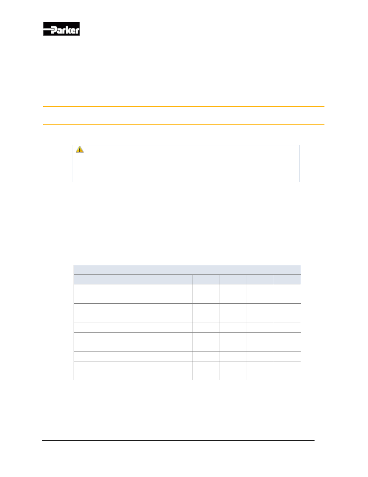
The following table provides specifications for the analog inputs:
Analog Input Specifications
Item
Min
Nom
Max
Unit
Input voltage range
0 6.6 V Input pin capacitance
.05 µF
Pull-up/down resistance
10
k
Response to step change
5
ms
Over-voltage
36
V
ADC reference voltage
3.3 V
Resolution - 10 bit ADC
3.2 mV
Offset error
50
mV
Drift error
±1
%
Open Load Voltage with 10k pull-up
1.36
1.46
1.56
V
2. Inputs
Page 15
User Guide 7
Inputs
2.1.2. Analog Input Configuration Options
All analog inputs are hardware configurable with an optional pull-up resistor to
+5V. The default configuration for all of the analog inputs has the resistor
populated.
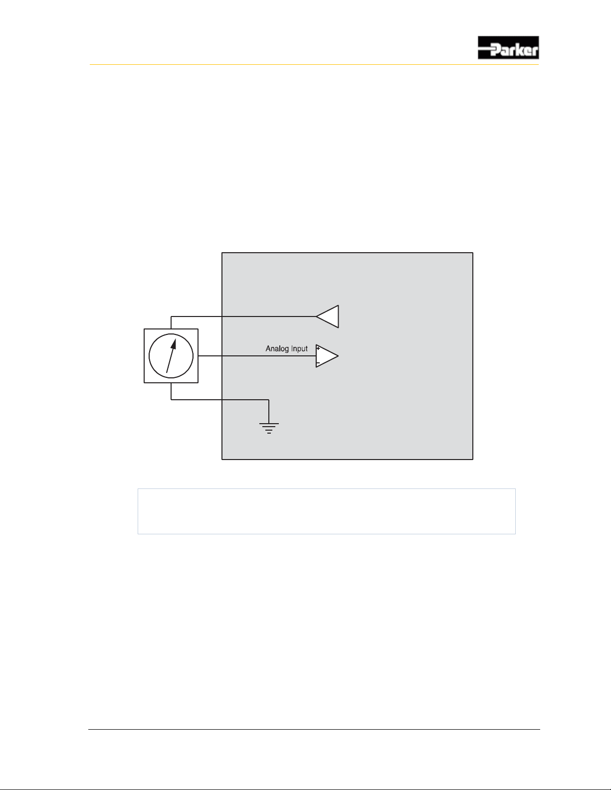
2.1.3. Analog Input Installation Connections
The sensor supply along with the sensor ground are the recommended power feed
to external sensors. This will prevent system noise from affecting the analog input
signals.
Internal to product
+5 Vdc Sensor Supply
Sensor Ground
Sensor
Figure 2: Analog input system noise connection
Note: It is important that the sensor supply does not connect to another
power source external to the DPS70. The sensor ground should also not
be connected to any other ground on the vehicle.
2.2. DPS70 Frequency Inputs
There is one type of frequency input in the DPS70:
▪ Direct coupled frequency input
Direct coupled frequency inputs are typically used to read pulse signals.
The DPS70 has 2 direct coupled frequency inputs:
▪ Frequency Input 1 to Frequency Input 2
Page 16
8 DPS70
Inputs
2.2.1. DPS70 Frequency Input Capabilities
Direct coupled frequency inputs allow you to read the frequency of external
signals that have a ground reference and no DC offset. These inputs are ideal for
use with hall-effect type sensors.
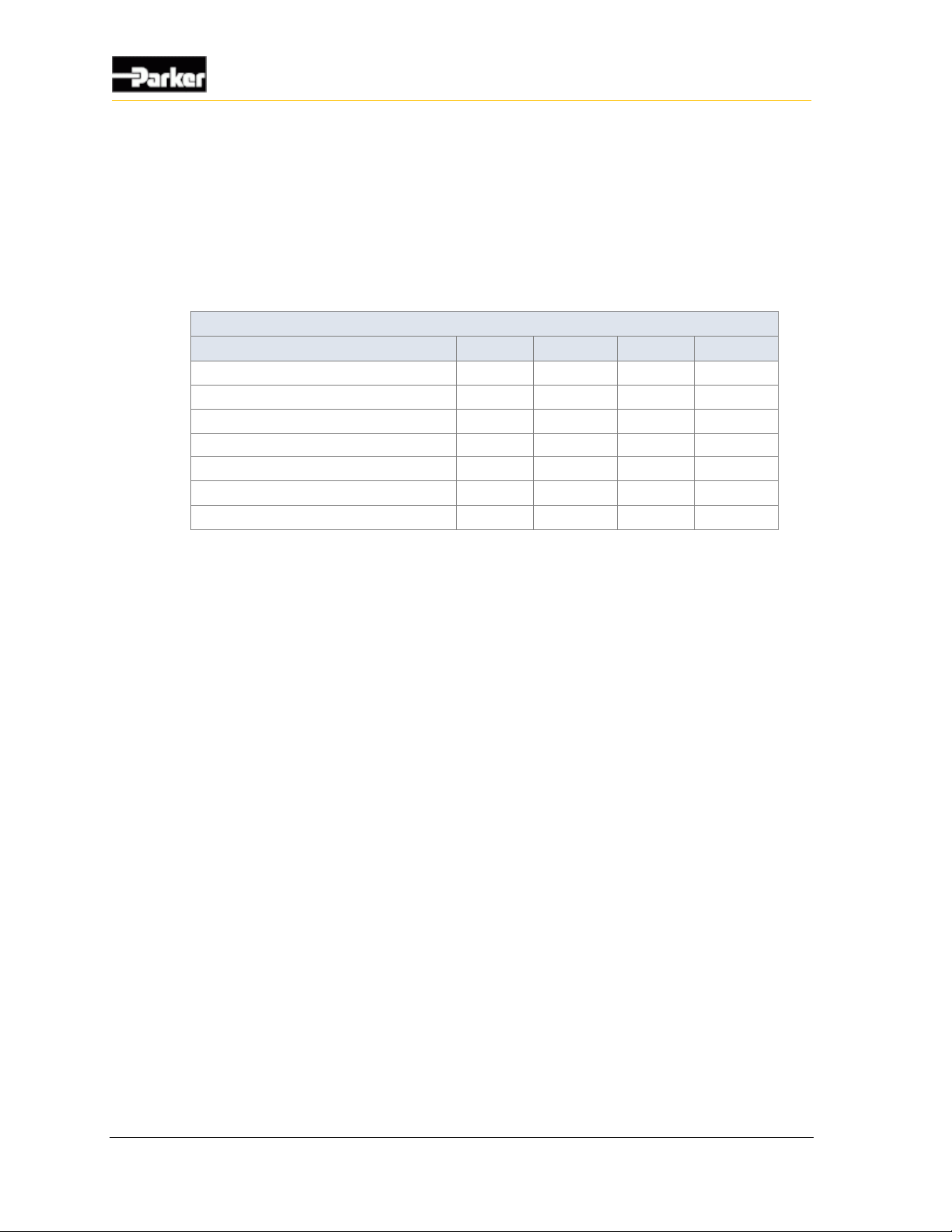
The following table provides specifications for the DPS70's direct coupled
frequency inputs:
Direct Coupled Frequency Input Specifications
Item
MIN
NOM
MAX
UNIT
Negative going switching threshold
1.56
V
Positive going switching threshold
3.82
V
Input capacitance at pin
.005
µF
Over-voltage
36
V
Frequency accuracy
5
%
Frequency range (note 1)
0 10000
Hz
Pull-up/down resistor
10
kΩ
Note 1: Electrically signals to 0 are possible, but the software will limit the minimum measureable frequency
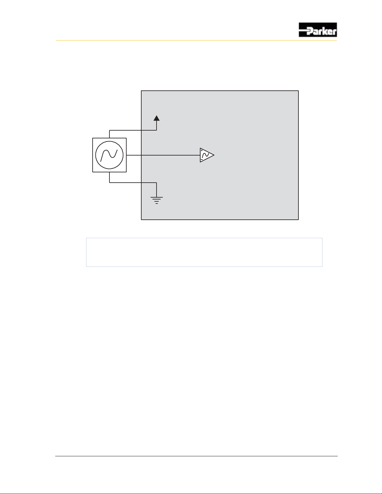
2.2.2. DPS70 Frequency Input Installation Connections
As with analog inputs, direct-coupled frequency inputs are also susceptible to
system noise and ground shift.
Page 17
User Guide 9
Inputs
The sensor supply along with the sensor ground are the recommended power feed
to external sensors. This will prevent system noise from effecting the frequency
input signals.
Internal to product
Sensor Voltage
Sensor Ground
Hall Effect Sensor
Direct Coupled
Frequency Input
Figure 3: Direct coupled frequency input installation connections
Note: It is important that the sensor supply does not connect to another
power source external to the DPS70. The sensor ground should also not
be connected to any other ground on the vehicle.
2.3. Digital Inputs
The DPS70 has 9 digital inputs:
▪ Digital Input 1 to Digital Input 3
▪ Digital Input 4 to Digital Input 9
All of the digital inputs have a 1.2 k resistor that provides the path for the wetting
current. The resistor is connected to ground or V
BATT
depending on the active state
of the input.
The DPS70 has 2 types of digital inputs:
▪ Hardware configurable active-high or active low, Digital Input 1 through
Digital Input 9
▪ Hardware configurable to be active-high "Wake-up input", Digital Input 1
through Digital Input 3
2.3.1. DPS70 Digital Input Capabilities
All digital inputs are hardware configurable as either an active-high input (with a
pull-down resistor), or an active-low input (with a pull-up resistor).
Page 18
10 DPS70
Inputs
Digital Input 1 to Digital Input 3 can be configured as wake-up inputs. When the
unit is in inactive power mode and a high signal is applied to a digital input
configured as a wake-up input, the unit will enter normal operating mode and
begin to operate.
Note: A digital input that is configured as a wake-up input must also be
hardware configured as an active-high input (pull-down resistor) to
prevent the system from continuously remaining powered up.
The following table provides specifications for the DPS70's digital inputs:
Digital Input Specifications - HW configurable as Active-High or Active-Low
Item
Min
Nom
Max
Unit
Input voltage range
0 32
V
Over-voltage
36
V
Inductive load protection
no
Input capacitance
.05
µF
Response time to step input
1.5
ms
Input high threshold
4.62
V
Input low threshold
1.98
V
Active-High Configuration
Input resistance to ground
1.2
kΩ
High threshold @ 9 V
1
kΩ
Low threshold @ 16 V
8.2
kΩ
Active-Low configuration
Input resistance to 3.3 V (note 1)
1.2
kΩ
High threshold
700
Ω
Low threshold
200
Ω
Note 1: Active low has pull-up to 3.3V through a diode to prevent backfeeding into power supply.
2.3.2. Digital Input Installation Connections
A digital input is typically connected to a switch that is either open or closed.
When the input is active-low
▪ When the switch is open, the pull-up resistor ensures that voltage exists on the
input signal, which will be interpreted by the DPS70 as inactive
▪ When the switch is closed, the input is connected to ground, which will be
interpreted by the DPS70 as active
Page 19
User Guide 11
Inputs
When the input is active-high
▪ When the switch is open, the pull-down resistor ensures that no voltage exists
on the input signal, which will be interpreted by the DPS70 as inactive
▪ When the switch is closed, the input is connected to battery voltage, which
will be interpreted by the DPS70 as active
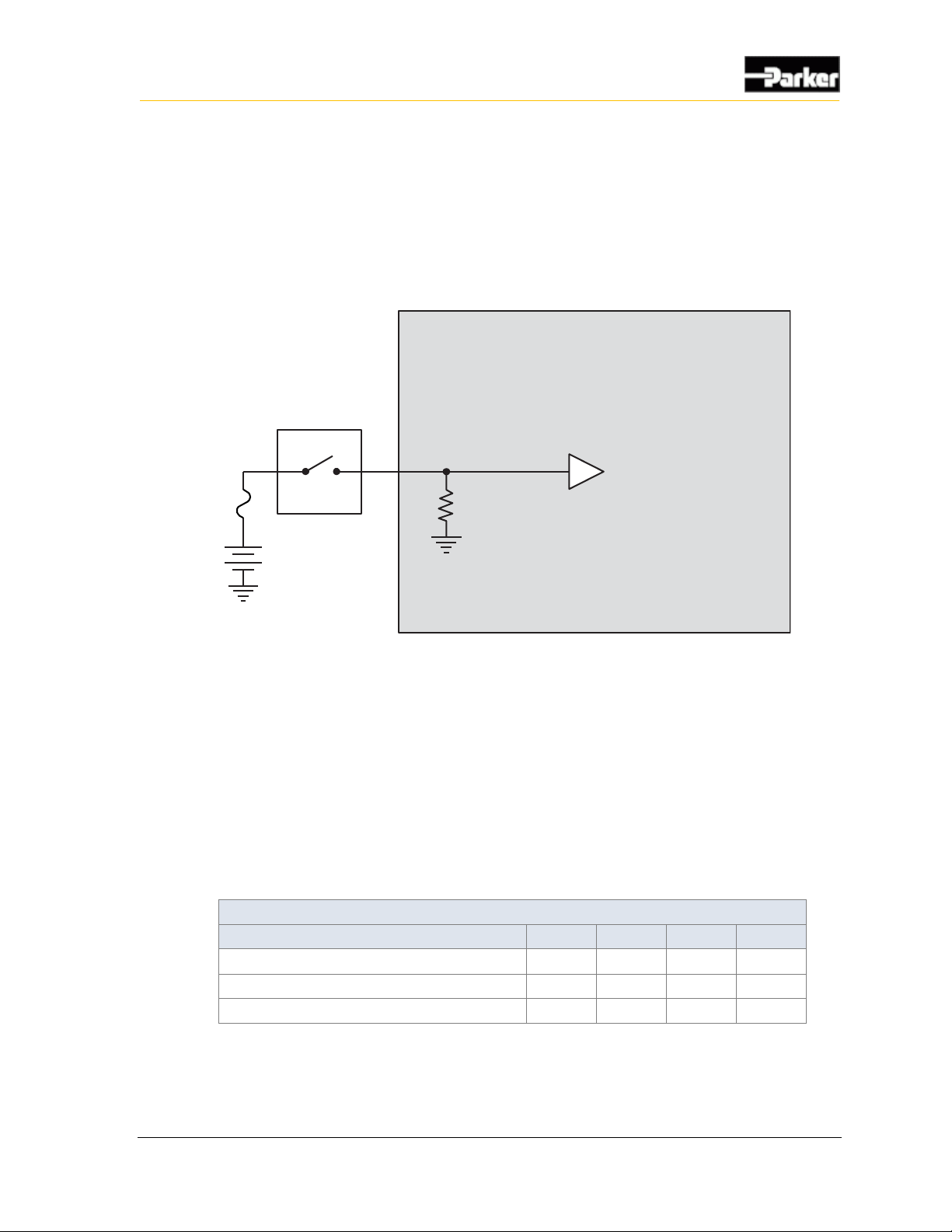
A typical active-high digital input connection is shown below:
Internal to product
Active High
Digital Input
Battery
Application Switch
Figure 4: Active high digital input
2.4. Video Inputs
The DPS70 accepts 5 NTSC/PAL camera inputs via BNC video connectors on the
rear of the unit. Inputs #1 and #2 feed are multiplexed to the same input of the
video decoder. Video inputs 3, 4 and 5 have dedicated decoder inputs. Up to 4
video feeds can be shown on the display simultaneously.
2.4.1. Video Input Capabilities
The following table provides specifications for the video inputs:
Video Input Specifications
Item
Min
Nom
Max
Unit
Input voltage range
-5.6 5.6 V Input resistance
75
Capacitance at pin
65
100
pF
Page 20

12 DPS70
Outputs
There are 2 types of outputs on the DPS70. There are two high-side outputs and a
5V sensor supply output.
▪ High-side outputs
▪ Sensor supply output
3.1. High-Side Outputs
The DPS70 has 2 high-side outputs:
▪ High-Side Output 1 to High-Side Output 2
High-side outputs are used for switching voltages to loads using either a pulse
width modulated (PWM) signal, or an on/off signal. They can also test for various
fault conditions.
3.1.1. High-Side Output Capabilities
All high-side outputs come with internal flyback diodes that provide protection
when driving inductive loads.
▪ When a high-side output is used as a PWM signal, a pulsed output signal is
provided by the DPS70, where the percentage of time that the output is “on”
vs. “off” is determined by the duty cycle of the signal. The duty cycle is
determined by the software
▪ When a high-side output is used as an on/off signal, the output provides
battery voltage when in the “on” state (the software is responsible for
switching high-side outputs on and off)
3. Outputs
Page 21
User Guide 13
Outputs
The following table provides specifications for the DPS70's high-side outputs:
High-Side Output Specifications
Item
Min
Nom
Max
Unit
Switchable voltage range
9 32
V
Over-voltage
36
V
Inductive pulse protection
yes
Output pin capacitance
.005
µF
Single Output
Output current (DC)
4
A
Output current (200 Hz)
1 2.5
A
Output current (500 Hz)
1.5
A
2 Outputs
Output current (DC)
3
A
Output current (200 Hz)
1.5
A
Output current (500 Hz)
.75
A
3.1.2. High-Side Output Configuration Options
The DPS70 high-side outputs may be configured with a software controlled 10
k pull-up resistor to battery for open load detection in the off state.
3.1.3. High-Side Output Installation Connections
When connecting the high-side outputs, note that:
▪ The high-side output is connected to an internal bus bar, which can be
connected to a +12 V or +24 V battery
▪ The high-side output can provide switched battery power to any load type in a
vehicle
▪ The high-side output has an internal flyback diode to absorb electrical energy
when the load is turned off
When connecting high-side outputs:
▪ Connect the load grounds close to the power grounds
▪ Do not connect high-side outputs to loads that will draw currents greater than
the maximum peak current or maximum continuous current
Page 22
14 DPS70
Outputs
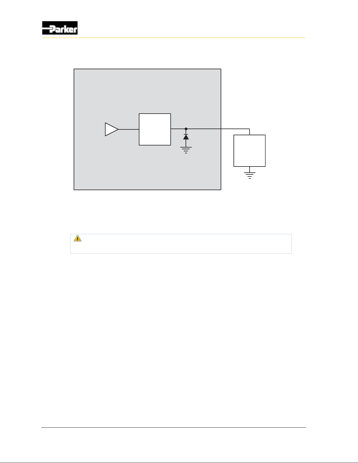
The following shows a typical high-side output connection:
Internal to product
High-Side
Output
Application
Load
Figure 5: Typical high-side output installation connections
The high-side driver is self-protecting and will shut off during a short circuit or if
an over temperature condition occurs. When the condition clears, the output
driver automatically tries to turn on the load.
Damage to equipment! Repeated cycling into a short circuit could
potentially lead to damage.
The output will be latched off if a short circuit or over temperature fault occurs. A
software cycling of the output driver state is required to turn the output on again.
3.1.4. High-Side Output Diagnostics and Fault Detection
The DPS70 high-side outputs have the ability to report many different fault
conditions. They are protected against short-circuit, overcurrent, open load, shortto-battery and short-to-ground faults.
3.1.4.1. Short Circuit
Short-circuit faults occur when a low-side output pin is shorted to battery and
produces an output current above the specified over-current trip point, causing an
over-current on the circuit.
When a short circuit or over-current fault is detected, the software automatically
turns off the output.
The short circuit trip time for low-side outputs depends on how the outputs are
configured.
The application software can be used to reset an output from a short circuit or an
over-current fault by turning the output off and then on again.
Page 23

User Guide 15
Outputs
3.1.4.2. Overcurrent
Overcurrent faults occur when a low-side output pin draws more current than the
specified overcurrent trip point.
When an overcurrent fault is detected, the hardware automatically turns off the
output.
The overcurrent trip time for low-side outputs is approximately 1 second.
Note: The DPS70 can be programmed to automatically reset an output from
an overcurrent fault.
3.1.4.3. Open Load
Open load faults occur when a high-side output pin is open circuit (not connected
to a load). The high-side output circuit uses a small amount of current on the
output pin to determine if an open load condition exists.
High-side outputs with current sense can detect an open load fault when on or off.
High-side outputs without current sense must be off to detect an open load fault.
3.1.4.4. Open Load
Open load faults occur when a low-side output pin is open circuit (not connected
to a load). The use of this feature operates as defined by the programmer
The low-side output circuit uses a small amount of current on the output pin to
determine if an open load condition exists.
Note: Low-side outputs must be on to detect an open-load fault.
3.1.4.5. Short-to-Battery
Short-to-battery faults occur when a high-side output pin is connected to battery
voltage.
The high-side output circuit uses voltage on the output pin to determine if a shortto-battery condition exists.
Note: High-side outputs must be off to detect a short-to-battery fault.
3.1.4.6. Short-to-Ground
Short-to-ground faults occur when a low-side output pin is connected to ground.
The low-side output circuit uses a small amount of current on the output pin to
determine if a short-to-ground condition exists.
Page 24
16 DPS70
Outputs
3.2. Sensor Supply Output
The DPS70 has 2 pins, labeled SENSOR_SUPPLY and SENSOR_GND, dedicated to
providing power to external sensors.
Warning! Do not drive more than 100 mA of current through the
SENSOR_SUPPLY pin. Doing so will cause the pin to protect itself by
dropping the voltage, which will result in a lack of power to the sensors,
causing unknown vehicle responses.
3.2.1. Sensor Supply Output Capabilities
SENSOR_SUPPLY is a 5 V linear power supply that is capable of continuously
providing 100 mA to external sensors.
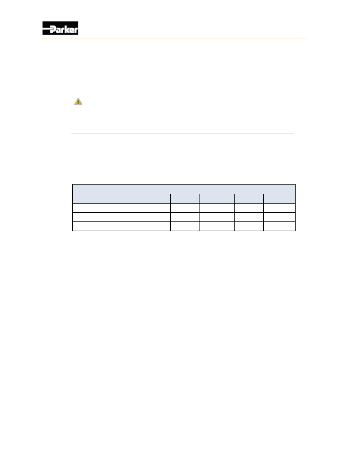
The following table provides specifications for the DPS70's sensor supply output:
Sensor Supply Output Specifications
Item
Min
Nom
Max
Unit
Output voltage
4.75
5.0
5.25
V
Current limit
100
mA
Over-voltage
36
V
3.2.2. Sensor Supply Output Installation Connections
The sensor supply and the sensor ground are intended to be the power source for
external sensors. It is important that these power signals do not connect to another
power source or ground external to the DPS70.
3.2.3. Sensor Supply Output Diagnostics and Fault
Detection
The sensor supply voltage is monitored as an analog channel. This allows for
increased accuracy of external sensors that are connected to the supply, and also
permits fault detection from short circuit to the supply.
Page 25
User Guide 17
Power
The DPS70 operates in a 12 V or 24 V system and is powered by a direct battery
connection. The direct battery input is protected against vehicle transients. It is
also protected against reverse battery voltage and abnormal high battery voltage
by shunting the internal current to ground and blowing the automotive fuse that
must be designed into the power circuit in the end system application.
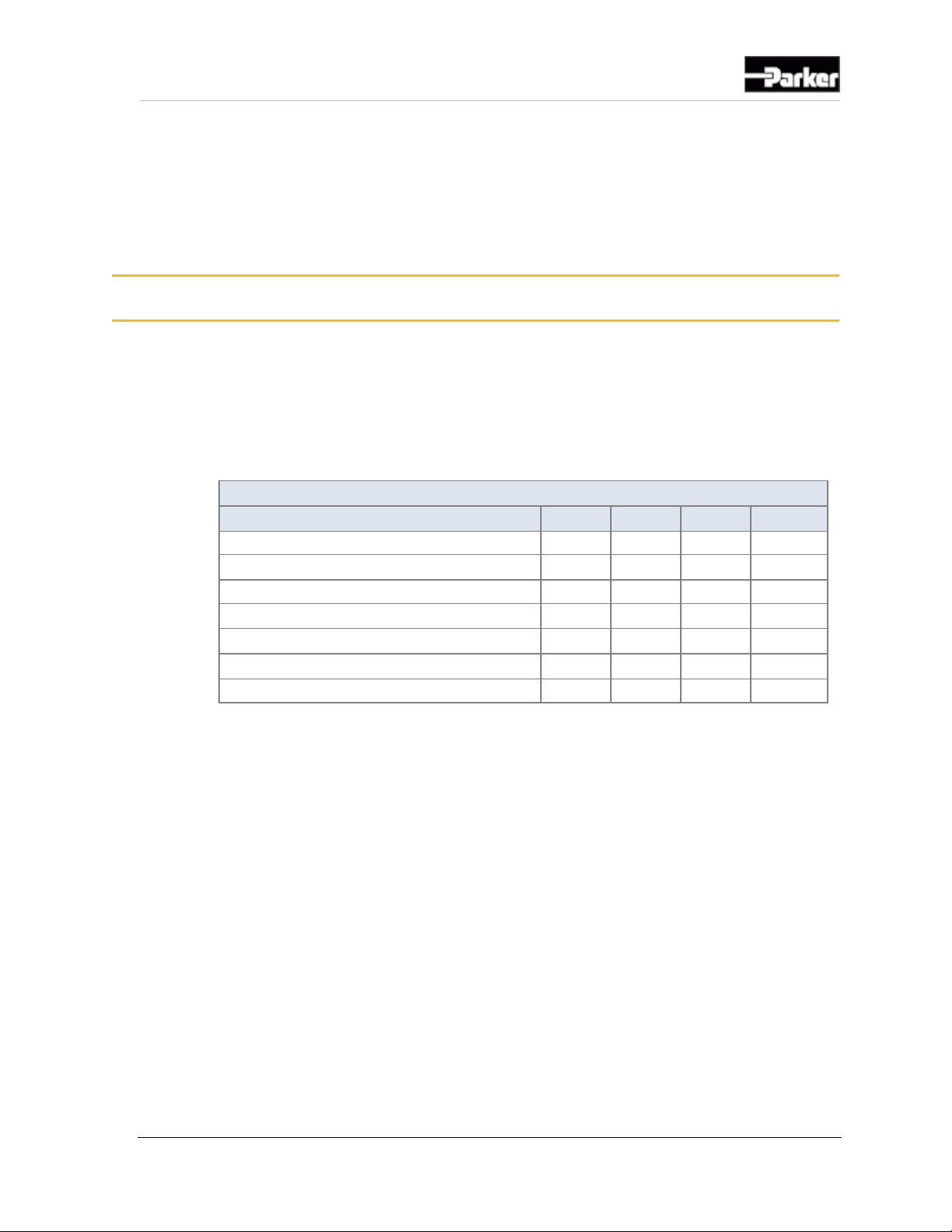
The following table provides specifications for the DPS70's power supply:
Power Specifications
Item
Min
Nom
Max
Units
Input voltage for normal operation
9 - 32
V
Minimum cranking voltage (note 1)
7 -
V
Overvoltage protection (DC)
- - 36
V
Reverse battery protection (note 2)
- - -36
V
Typical current at 12 V (note 3)
-
700
mA
Off-state current, V
BATT
of 12 V
2
mA
Rating of External Fuse
- - 10
A
Note 1: The unit will operate below 9V, down to 7V, but the warning LED’s may be dim.
Note 2: The unit is protected against a reverse battery condition by causing an external fuse to blow.
Note 3: Does not include current required for outputs
4. Power
Page 26
18 DPS70
Communication
The types of communication available to the DPS70 are Controller Area Network
(CAN) communication, USB host, USB device, RS232 and Ethernet.
5.1. CAN
There are two CAN buses on the DPS70 that meet the CAN2.0B specification.
All buses can be hardware configured for an internal 120 Ω termination resistor.
The resistor is not populated in the default version.
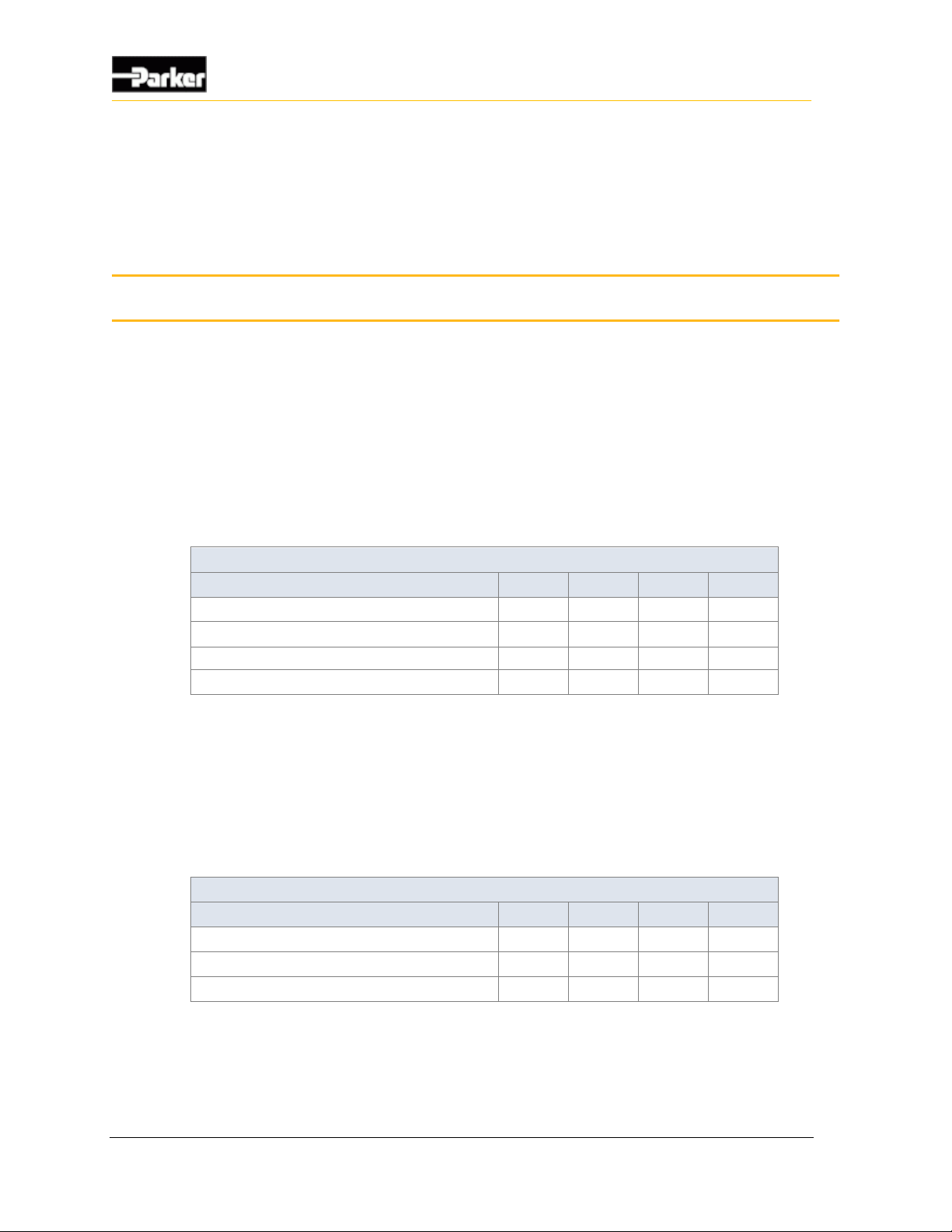
The following table provides specifications for the CAN:
CAN Specification
Item
Min
Nom
Max
Unit
Over-voltage
30 V On-board terminator (optional)
120
Baud rate
125
250
500
Kbps
Capacitance
33 pF
5.2. USB Host
The DPS70 supports one USB Host port capable of high speed USB 2.0. The
USB Host port will support a device with current drain not exceeding 500mA.
The following table provides specifications for the USB host:
USB Host Specifications
Item
Min
Nom
Max
Unit
Communication speed - High Speed
480
Mbps
Capacitance of I/O to ground
2.5
3.5
pF
Reverse standoff voltage (note 1)
5
V
Note 1: USB connectors are not rated to survive a short to vehicle battery.
5. Communication
Page 27
User Guide 19
Communication
5.3. USB Device
The DPS70 supports one isolated USB device capable of full speed USB 2.0.
When there is no software installed, the USB device slot will default to being
enabled when power is applied. Once the board is programmed, it is up to the
application or driver layer to determine whether or not this interface is to remain
active.
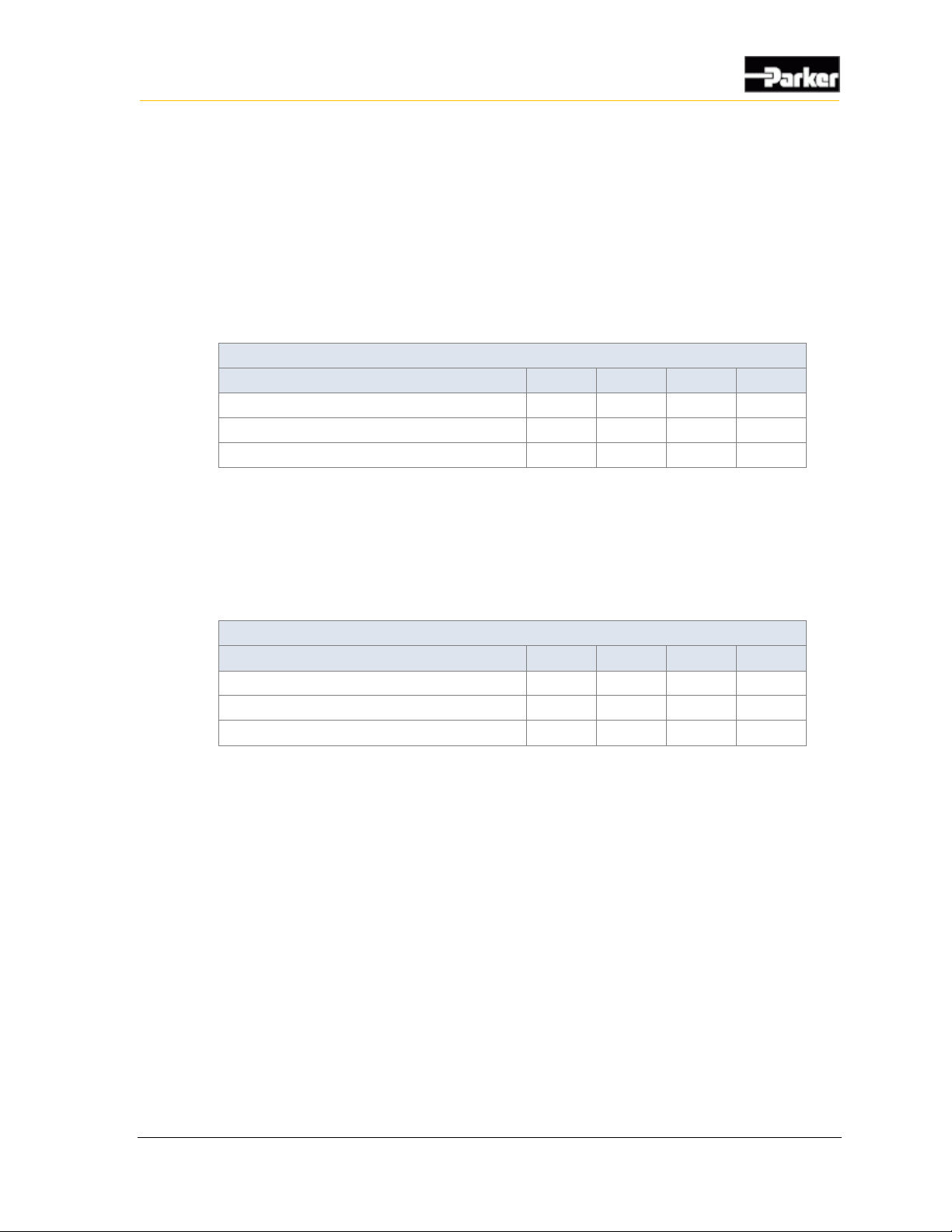
The following table provides specifications for the USB device:
USB Device Specifications
Item
Min
Nom
Max
Unit
Communication speed - Full Speed
12
Mbps
Capacitance of I/O to ground
2.5
3.5
pF
Reverse standoff voltage (note 1)
5
V
Note 1: USB connectors are not rated to survive a short to vehicle battery.
5.4. RS232
The UART is an external serial port used as a 3 wire serial interface (Rx, Tx,
Gnd) operating up to 115200, 8, N, 1.
The following table provides specifications for the RS232:
RS232 Specifications
Item
Min
Nom
Max
Unit
Communication speed
115.2
kbps
Output capacitance
350
pF
Series resistance
470
5.5. Ethernet
The Ethernet port on the main microprocessor supports the Ethernet MAC layer
and an external physical layer is used from the Ethernet transceiver.
The Ethernet interface supports both 10 Mbps and 100 Mbps interfaces.
Page 28
20 DPS70
Display
The display LCD is a 7.0” TFT LCD with In Plane Switching (IPS) for a wide
viewing angle and has a capacitive touch screen.
The following table provides specifications for the DPS70's display:
Display Specifications
Item
Min
Nom
Max
Unit
Size
Aspect ratio
16:9
Screen size
7
inch
Active area
152.4x91.44
mm
Resolution
800x480
pixels
Viewability
Viewing angle (CR>10), U/D
178 degrees
Viewing angle (CR>10), R/L
178 degrees
Color
8 bit
Contrast ratio (CR)
560
800
Brightness
360
450 cd/m²
Backlight lifetime
30,000
hrs
Environmental
Operating temperature
-30 +80
°C
Storage temperature
-30 +85
°C
Interface - LVDS
LVDS clock
25
MHz
6. Display
Page 29
User Guide 21
Display
The following table provides the touchscreen specifications for the DPS70's
display:
Touchscreen Specifications
Item
Min
Nom
Max
Unit
Surface hardness
6 - 7
H
Transmissivity
90 %
Operating temperature
-20 +70
°C
Storage temperature
-30 +85
°C
Impact rating
IK06
Response time
60 ms
Page 30
22 DPS70
Gauge Area
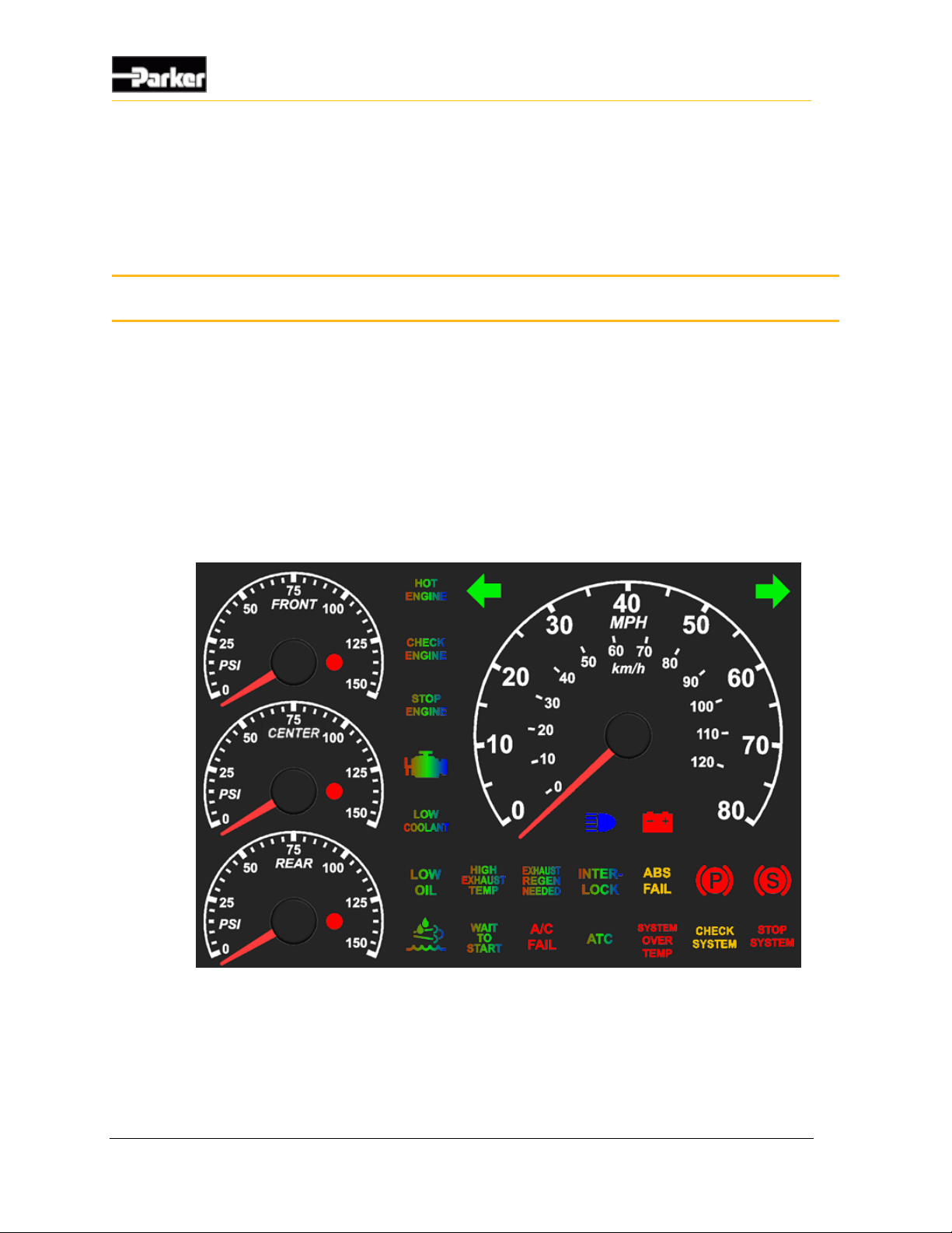
The DPS70 has a large area for gauges that includes 26 status indicator LEDs and
4 analog stepper motor gauges.
7.1. Status Indicator LEDs
There are 26 status LEDs (telltales) on the DPS70.
The brightness of the telltales can be adjusted through software. This adjustment
controls the brightness of all of the telltales, and the analog gauge backlighting,
together.
Figure 6: DPS70 telltale LEDs and color locations
7. Gauge Area
Page 31
User Guide 23
Gauge Area
The colors of the LEDs are defined as follows:
▪ 6 LEDs are RGB with feedback
▪ 6 LEDs are RGB
▪ 2 LEDs are Green
▪ 2 LEDs are Amber
▪ 6 LEDs are Red
▪ 1 LED is Blue
▪ 3 LEDs are Red for analog gauge warnings
Note: The tricolor LEDs have the red/green brightness ratio set so that they
provide an amber color similar to that of the individual amber LED. As
a result, when all three colors in the tricolor LED are turned on, the
color is not white.
The icons associated with each status LED are determined by the overlay. The
default overlay is shown above, but it can be customer-specific.
7.2. Analog Gauges
There are four analog gauges on the DPS70. They are implemented using stepper
motors and can be micro-stepped. Micro-stepping results in pointer movement of
1/12 ° per step. The motors have internal stops and the pointers are zeroed on each
power cycle.
The following table has the specifications for the analog gauges:
Analog Gauge Specifications
Item
Min
Nom
Max
Unit
Sweep range - small gauge
225 degrees
Sweep range - large gauge
250 degrees
Step size
1/12
degrees
Maximum sweep speed
600
deg/s
The velocity and acceleration of the gauges is controlled through software, and
can be adjusted to meet the specific requirements of the application.
7.2.1. Gauge Backlighting
The gauges have backlighting for the sweep area and the pointers. The pointers
are backlit red and gauge areas are backlit blue. The brightness of the pointer and
gauges is done together with the status LEDs.
Page 32
24 DPS70
Gauge Area
7.3. Buzzer
The DPS70 has a rear facing piezo transducer. It has two volume settings and
frequency control. The volume is controlled by adjusting the duty cycle with 25%
being low volume and 75% being high volume.
The following table provides specifications for the DPS70's buzzer:
Buzzer Specifications
Item
Min
Nom
Max
Unit
Resonant frequency
2900
3400
3900
Hz
Sound pressure level @ 10 cm (note 1)
110
dBa
Voltage
1
12
36
V
Operating temperature range
-40 +85
°C
Storage temperature range
-40 +85
°C
Note 1: SPL at resonant frequency with product not installed in vehicle and the distance is off the rear cover.
7.4. Real Time Clock
The real time clock is incorporated in the gauge co-microprocessor. The primary
power for the clock is from the direct battery connection. If the direct battery
connection is not present, power is supplied by the lithium backup battery in the
unit. The backup battery is 3 V 1000 mAh. Minimum lifetime is 10 years when
disconnected from the vehicle battery.
Page 33
User Guide 25
Connectors
The connectors on the rear panel of the DPS70 are;
▪ MX150 – Vehicle Harness Connectors
▪ USB Type A - Host
▪ USB Type B - Device
▪ RJ45 - 10/100 Ethernet
▪ BNC - Video Camera Inputs
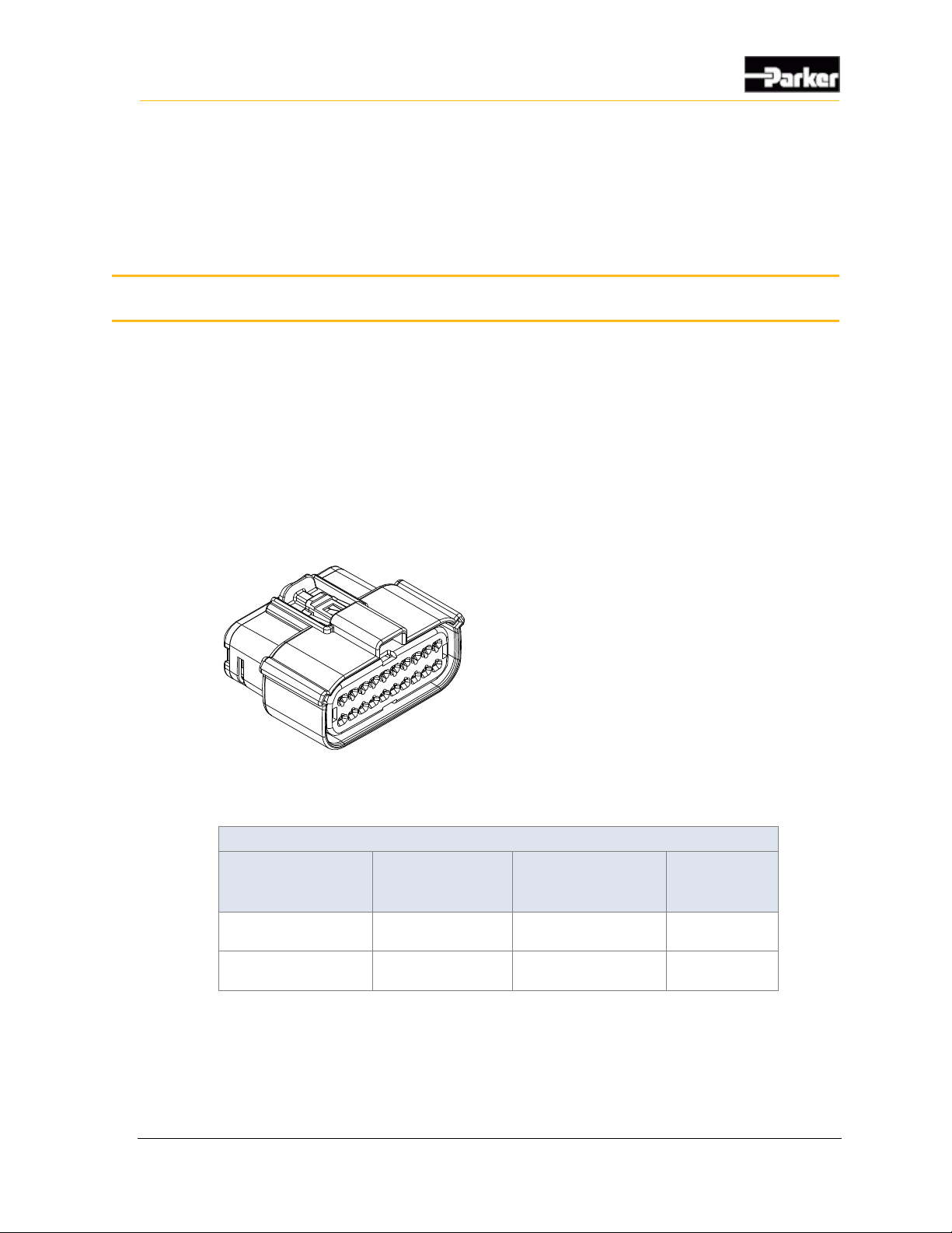
The Molex MX150 connectors are used to interface the DPS70 to the vehicle.
Figure 7: MX150 20-pin connector
Mating Connector Part Numbers
Connector
Shell part no.
with locking clip
Shell part no.
without locking
clip
Terminals
J1 connector (gray),
20-pin, key option B
334722007
334722002
330012004 (1820 AWG)
J2 connector (black),
20-pin, key option A
334722006
334722001
330012004 (1820 AWG)
8. Connectors
Page 34
26 DPS70
Connectors
8.1. Pinouts
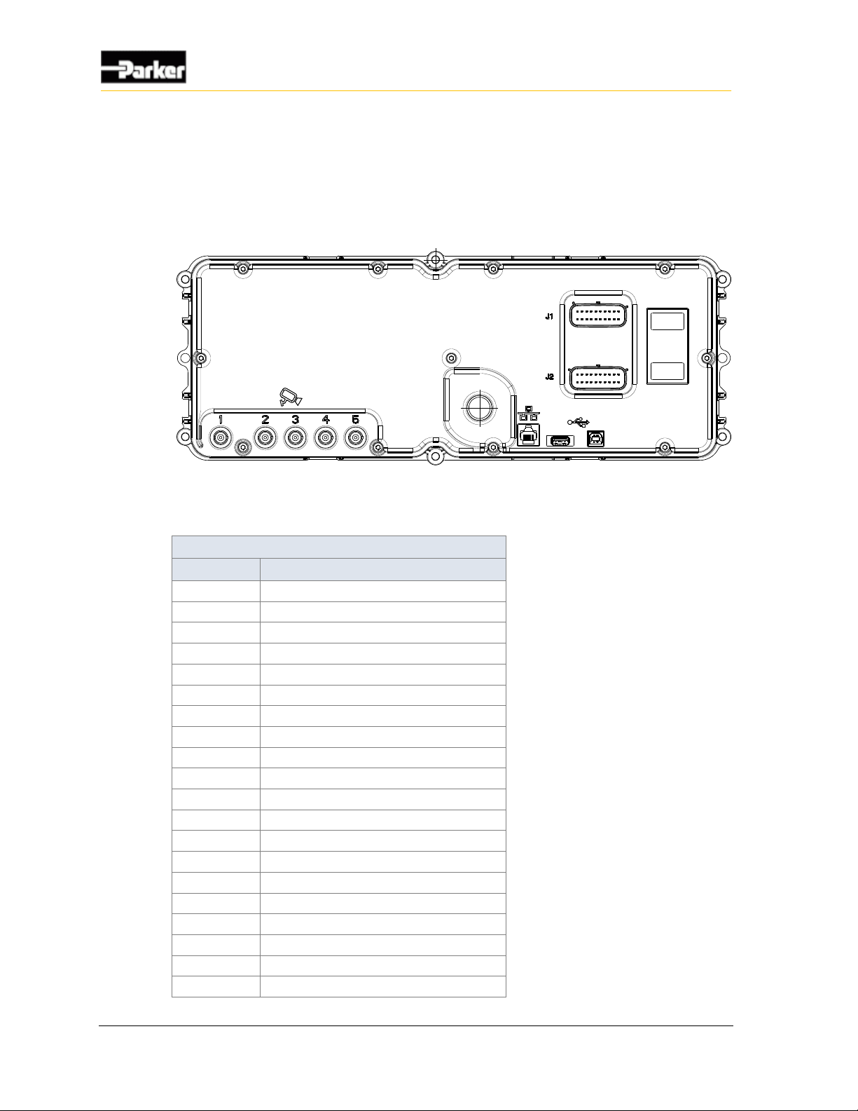
The pins in connector positions J1 and J2 connect to inputs, outputs, power and
CAN communication channels.
Figure 8: DPS70 rear view showing connectors
The following tables show the pinouts for each connector:
J1 Connector Pinout
Pin
Function
1
Digital input 2 (Wake up)
2
Digital input 1 (Wake up)
3
CAN 2 shield
4
CAN 2 low
5
CAN 2 high
6
CAN 1 shield
7
CAN 1 low
8
CAN 1 high
9
Negative battery
10
Positive battery
11
Digital input 3 (Wake up)
12
Analog input 3
13
Analog input 4
14
Frequency input 1
15
Sensor supply ground
16
Analog input 1
17
Analog input 2
18
High-side output 1
19
High-side output 2
20
Positive battery
Page 35
User Guide 27
Connectors
J2 Connector Pinout
Pin
Function
1
NC
2
NC 3 NC 4 Digital input 4
5
Analog input 10
6
Analog input 9
7
Analog input 8
8
Analog input 7
9
Analog input 6
10
Analog input 5
11
Digital input 5
12
Digital input 6
13
Frequency input 2
14
Digital input 7
15
Negative battery
16
RS232 Rx
17
RS232 Tx
18
Digital input 8
19
Digital input 9
20
Sensor supply +5V
Page 36

28 DPS70
Mounting
It is up to the original equipment manufacturer (OEM) to ensure the product is
securely mounted to the vehicle.
The following guidelines are related to physically attaching the DPS70 to a
vehicle:
▪ Mount the DPS70 onto a flat dash panel, from behind/below
▪ The DPS70 should be secured with screws in all 6 screw holes using #8-32
screws from the front/top
▪ The screws should be tightened according to the fastener manufacturer's
tightening torque specifications
▪ The dash panel must include a cutout(s) for the viewing areas of the gauges
and LCD
▪ A bezel (trim ring) is recommended (usually specified and supplied by the
OEM)
▪ Clip the bezel onto the cluster from the front after the cluster is installed into
the dash panel (the dash panel must allow clearance for the bezel mounting
clip features)
Refer to Parker product drawing for cluster dimensions and further mounting
details. For more information contact your Parker Vansco Account
Representative.
9.1. Mechanical requirements
When mounting the DPS70, ensure that
▪ the DPS70 is oriented to the operator's viewing angle
▪ the wire harness connects easily to the connectors and that the bend radius is
adequate
▪ the harness is shielded from harsh impact
▪ the buzzer hole is not blocked
9. Mounting
Page 37
User Guide 29
Mounting
9.2. Dimensions
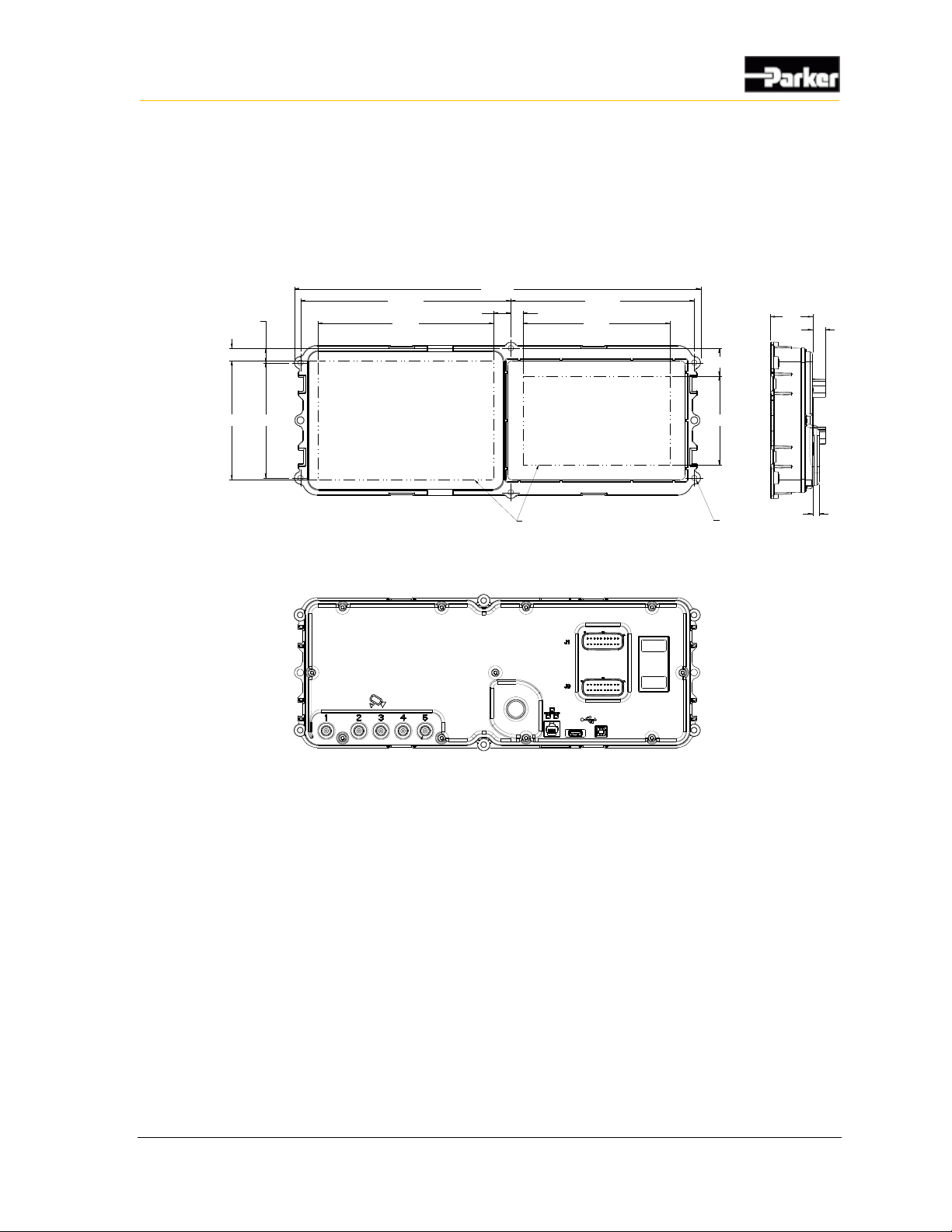
The overall cluster envelope (including a Bezel) is nominally 472.4mm x
184.0mm x 76.6mm. Refer to Parker product drawings for more detail. For more
information contact your Parker Vansco Account Representative.
43.9
13.3
(92.4)
7.0
6X THREADED
BRASS INSERTS
#8-32 THRU
13.0
2X 15.0
(183.0)
2X 219.0
423.0
18.0
12.3
(153.4)
2X 191.0
(124.0)
2X 120.0
28.8
(VIEWING AREA)
UNITS = mm
FRONTVIEW
BEZEL NOTSHOWN
REAR VIEW
BEZEL NOTSHOWN
Figure 9: DPS70 dimensions without bezel
Page 38

30 DPS70
Environmental Protection
The DPS70 is manufactured to meet stringent industry standards. A summary of
tested specifications was not available when this document was published. The
information will be included in future editions. Please contact your Parker Vansco
representative for more details.
10. Environmental Protection
Page 39

User Guide 31
AC-coupled
A circuit that eliminates the DC offset voltage of the signal. This circuit is
typically used with frequency inputs that have a DC offset. Note that the DC
offset value varies by product.
active high
Input type that is on when it reads a battery voltage level, and off when it is
floating or grounded.
active low
Input type that is on when it reads a ground voltage level, and off when it is
floating or connected to battery voltage.
ADC
Analog to digital conversion.
aliasing
In analog-to-digital conversion, distortion that occurs when the analog signal
being sampled has a frequency greater than half the sample rate. An example of
aliasing is the wagon-wheel effect often seen in films, in which a spoked wheel
appears to rotate differently from its true rotation.
amplified
A circuit that applies a gain with a value greater than one (1) to a measured signal,
which is typically used with analog inputs.
analog input
An input that allows a voltage level to be read and converted to discrete digital
values within a microprocessor.
anti-alias filtering
Filters incorporated in hardware that ensure the analog value being read by the
module does not have a frequency component greater than half the sample rate.
11. Glossary
Page 40

32 DPS70
Glossary
application software
A level of software that makes a product (hardware) perform desired functions for
the end user.
attenuation
A gradual decrease in a current's intensity. Such a decrease may occur naturally,
or intentionally through the use of an attenuator.
bi-directional pin
A pin that can be used as either an input or output.
black box
A custom-compiled algorithm written in C programming language that allows a
system designer to implement algorithms that are not possible in ladder logic.
bus
A subsystem that transfers data between components within a computer or
between computers.
bus bar
A strip or bar of copper, brass, or aluminum that conducts electricity.
CAN bus
See controller area network (CAN) bus.
CAN high
The positive wire in a shielded twisted-pair cable, which, when connected with a
CAN low, provides a complete CAN differential signal.
CAN low
The negative wire in a shielded twisted-pair cable, which, when connected with a
CAN high, provides a complete CAN differential signal.
CAN shield
The shielding that wraps around the CAN high and CAN low wires in a shielded
twisted-pair cable.
clamped
Voltage that is prevented from going above a specific value.
CMOS
See Complementary Metal-Oxide Semi-Conductor.
Page 41

User Guide 33
Glossary
complementary metal-oxide semi-conductor
A technology for constructing integrated circuits that yield high speed combined
with low power consumption. CMOS technology is used in computer chips.
controller area network (CAN) bus
A communications network bus that permits data from sensors and other
equipment within a motor vehicle to communicate with each other and, through
telltales and other diagnostic tools, with the operator.
controller I/O board
A development product that allows users to test products on a bench in a
development environment before installing the product on a vehicle.
controller module
Any module that has embedded software used for controlling input and output
functions.
current feedback
A circuit that allows software to measure the amount of current provided by the
outputs. This circuit is typically connected to an analog input that is connected to
the microprocessor. Also known as current sense or current sensing.
current feedback control
Varying the duty cycle of an output so that the output provides a desired amount
of current to the load.
current sensor
A device that detects electrical current in a wire and generates a signal
proportional to it.
data link adaptor (DLA)
A development tool that connects the CAN bus to a personal computer (through a
USB or RS232 port), so that programming and diagnostics can be performed on
the product before installing it in a vehicle.
DC-coupled
DC coupling passes the full spectrum of frequencies including direct current. The
signal being read by this circuit must fall within the detection threshold range
specified for the input.
dead-fronted
A situation in which the telltales are inactive and the display appears black.
Page 42

34 DPS70
Glossary
de-rating
The reduction of the rated output current level to a value less than the specified
rating. De-rating is typically done so that a product does not overheat.
digital input
An input that is typically controlled by an external switch that makes the input
either active (on), or inactive (off).
dimension
To select values so that they generate optimal results.
driver (hardware)
An electronic device that switches power or ground to an external load. The driver
is a key component used in all output circuits.
driver (software)
A block of software that provides access to different hardware components.
duty cycle
The time that a device spends in an active or operative state, expressed as a
fraction or percentage of the total cycle time (start, operate, stop).
electromagnetic compatibility (EMC)
The ability of a component within a system to function correctly despite
electromagnetic interference propagated by other components in the system.
electromagnetic susceptibility
The ease with which a device, component, circuit, etc., suffers a degradation of
performance when subjected to electromagnetic energy.
EMC
See electromagnetic compatibility.
FET
See field effect transistor.
field-effect transistor (FET)
A transistor whose flow of charge carriers is controlled by an external electric
field.
floating input
An input, isolated from a ground connection, that does not resist being pulled high
or low when inactive.
Page 43

User Guide 35
Glossary
flyback
A voltage spike seen across an inductive load when its supply voltage is suddenly
reduced or removed.
frequency input
An input that allows a frequency value to be read from an oscillating input signal.
gain
To increase the voltage level of an input signal to maximize the resolution of an
input.
general purpose input
An input that can be used as an analog, digital, or frequency input.
ground level shift
An undesirable condition in which the ground level elevates. This condition can
cause inputs to activate when they shouldn't.
half-bridge
The simultaneous use of a high-side switch and a low-side switch in order to
provide a load having both a battery voltage and a ground.
harness address pins
The pins a product uses to identify itself within a system.
H-bridge
A combination of two half-bridge circuits used together to form one circuit. Hbridges provide current flow in both directions on a load, allowing the direction of
a load to be reversed.
high-side output
An output that provides switched battery voltage to an external load.
hysteresis
The tendency, either by nature or design, for a device or system to remain
temporarily (lag) in one state before switching to another. Hysteresis might be
intentionally added to electronic circuits prevent unwanted rapid switching. A
furnace, for example, is designed to remain on or off for some time after the room
temperature reaches the thermostat's set point.
Page 44

36 DPS70
Glossary
inductive load
A load that produces a magnetic field when energized. Inductors are electrical
components that store energy and are characterized by the following equation:
E
stored
LI
2
2
1
inrush current
The peak instantaneous input current drawn by an electrical device when first
turned on.
keyed
Notches, slots, or other mechanical devices added to connectors so that they are
connected to their mates with the proper orientation.
ladder logic
A programming language often used in industrial-control settings to control
electromechanical devices in a relay. Programs written in this language resemble
ladders: two vertical rails with a series of horizontal rungs—each representing a
logical rule—between them. Ladder programs for Parker Vansco products are
written using Vansco Multiplexing Module Software (VMMS).
leakage current
Current that flows when the ideal current is zero.
LIM16H
A light indicator module with 16 inputs that are hardwired to telltales.
load
Any component that draws current from a module and is typically switched on
and off with outputs. Examples include bulbs, solenoids, motors, etc.
load dump
A surge in the power line caused by the disconnection of a vehicle battery from
the alternator while the battery is being charged. The peak voltage of this surge
may be as high as 120 V and may, unless precautions are taken, affect other loads
connected to the alternator.
logic ground
Ground pins for the microprocessor and logic peripherals.
logic power
Power pins for the microprocessor and logic peripherals.
Page 45

User Guide 37
Glossary
low-side output
An output that provides a switched ground voltage to an external load.
module address
The binary address of the DPS70, as determined by the harnessing.
multiplexing
Transmitting multiple messages simultaneously over one channel in a local area
network.
network fault flag
A special flag available in ladder logic that indicates a network problem exists
(when master power is inactive and ladder logic references VMM(s) that are not
available, or VMM(s) do not contain the same version of ladder logic).
Nyquist criterion
A theorem stating that a reconstructed signal will match the original signal
provided that the original signal contains no frequencies at or higher than one-half
the sampling frequency
open load
The disconnection of a load from an output, often because of a broken or worn
wire or connector pin.
overcurrent
A fault state that occurs when a load draws more current than specified for an
output, which results in the output shutting down to protect the circuitry of the
product.
overvoltage
A situation in which the voltage in a circuit rises above its upper design limit.
panel-mounted
A device mounted into a flat panel that has a cutout in the shape of the device.
PID controller
See proportional-integral-differential (PID) controller.
power control input
A digital input that is used to turn on the product. When the input is active, the
product turns on and operates in normal mode; when the input is inactive, the
product powers down and will not operate.
Page 46

38 DPS70
Glossary
procurement drawing
A mechanical drawing showing the dimensions, pinouts, and implemented
configuration options for a Parker Vansco product.
proportional-integral-differential (PID) controller
A system or device controller that, through constant feedback about differences
between the desired state and the current state, adjusts inputs accordingly. An
example of such a controller is one that prevents a vehicle from traveling faster
than a specified speed, regardless of the amount of pressure on the gas pedal.
pull-down resistor
A resistor that connects an input to a ground reference so that an open circuit can
be recognized by the microprocessor, which is typically used on active-high
digital inputs or analog inputs.
pull-up resistor
A resistor that connects an input to a voltage reference so that an open circuit can
be recognized by the microprocessor, which is typically used on active-low digital
inputs or analog inputs.
pulse counter
A device that detects and counts pulses occurring on a frequency input for a given
period of time.
pulse-width modulation (PWM)
A digital logic circuit programmed to produce a pulse having any desired period
or duty cycle. It is a means of controlling variable speed motors. See also duty
cycle.
PWM
See pulse-width modulation.
quadrature
A shaft rotation monitoring technique that provides the speed, position, and
direction of the shaft.
RMS
Root Mean Square. This is a statistical measure of the magnitude of a varying
quantity.
RS232
An inexpensive type of serial communication used on most PC and laptop
computers that doesn't define the communication protocol, making it attractive for
Page 47

User Guide 39
Glossary
embedded applications. RS232 is an older technology that is slowly being phased
out of production in favor of USB.
sample rate
The rate at which the microprocessor reads analog voltage levels.
sensor power
A regulated voltage output that provides a set voltage level for analog sensors
attached to the product.
shielded twisted-pair cable
A type of cable used for CAN communication that consists of two wires (CAN
high and CAN low) twisted together. These wires are covered by a shield material
(CAN shield) that improves the cable's immunity against electrical noise.
short-to-battery
A fault state that occurs when an input or output pin is connected to battery
power, potentially resulting in high current flow.
short-to-ground
A fault state that occurs when an input or output pin is connected to system
ground, potentially resulting in high current flow.
sleep mode
A low-power mode that is assumed by the DPS70 when the voltage on the power
control inputs drop below a certain value.
slew rate
1. The maximum rate at which an output voltage can swing across its full
dynamic range.
2. The maximum rate at which a control system can react to an adjustment or
change.
steady state
In a circuit or network, a state of equilibrium undisturbed by transients. Compare
transient.
switch outputs
An output that is digital in nature. It switches to battery and/or ground levels.
switching threshold current
The minimum amount of current required in an input before its associated telltale
illuminates.
Page 48

40 DPS70
Glossary
system noise
Electrical interference generated from external devices that affect the behavior of
inputs, outputs, and sensors. System noise can be generated from things like the
vehicle alternator, engine, transmission, etc.
telltale
An optical signal that, when illuminated, indicates the status of a system within a
motor vehicle.
temperature sensor
The temperature sensor is specified to be accurate to ±4 °C over the whole -40 °C
to 125 °C temperature range.
terminating resistor
A resistor placed at the end of a wire to absorb signals and prevent them from
reflecting back into the line and causing interference.
TFT LCD
See thin-film transistor liquid-crystal display.
thin-film transistor liquid crystal display (TFT LCD)
A liquid crystal display in which each pixel of the screen is powered separately by
a transistor.
transflective liquid crystal display
A liquid crystal display that reflects and transmits light, permitting readability in
varying light conditions.
transient
A short-lived burst of energy caused by a sudden change of state. Compare steady
state.
transient voltage suppressor
A Zener diode engineered for high-power current switching. See also Zener
diode.
translucent
The state in which an icon diffuses light so that objects on the other side of the
icon are not clearly visible (also known as semi-transparent).
transorb
See transient voltage suppressor.
Page 49

User Guide 41
Glossary
transparent
The state in which you can see through an icon when the telltale is inactive.
trip time
The amount of time it takes a circuit to protect itself after a fault occurs.
VMM
Vansco Multiplexing Module
VMM system
A collection of multiplexing products that function together in a system through
software.
VMMS
Vansco Multiplexing Module Software.
wake on CAN
A method of power control that makes the product turn on when a CAN message
is received from another module in the system, and turn off as determined by the
application software.
wetting current
The minimum current needed to flow through a mechanical switch to break
through any film of oxidation that may be on the switch contacts.
Zener diode
A diode that allows current to flow in the reverse direction when voltage is above
a certain value.
Page 50

User Guide 42
A
About the DPS70 • 1
AC-coupled • 31
active high • 31
active low • 31
ADC • 31
aliasing • 31
amplified • 31
Analog Gauges • 23
analog input • 31
Analog Input Capabilities • 6
Analog Input Configuration Options • 7
Analog Input Installation Connections • 7
Analog Inputs • 6
anti-alias filtering • 31
application software • 32
attenuation • 32
B
bi-directional pin • 32
black box • 32
bus • 32
bus bar • 32
Buzzer • 24
C
CAN • 18
CAN bus • 32
CAN high • 32
CAN low • 32
CAN shield • 32
clamped • 32
CMOS • 32
Communication • 18
complementary metal-oxide semi-conductor • 33
Connectors • 25
Construction regulations • vii
controller area network (CAN) bus • 33
controller I/O board • 33
controller module • 33
current feedback • 33
current feedback control • 33
current sensor • 33
D
data link adaptor (DLA) • 33
DC-coupled • 33
dead-fronted • 33
Declaration of Regulatory Compliance • 5
de-rating • 34
Diagram conventions • 4
digital input • 34
Digital Input Installation Connections • 10
Digital Inputs • 9
dimension • 34
Dimensions • 29
Display • 20
DPS70 Digital Input Capabilities • 9
DPS70 Frequency Input Capabilities • 8
DPS70 Frequency Input Installation Connections • 8
DPS70 Frequency Inputs • 7
driver (hardware) • 34
driver (software) • 34
duty cycle • 34
E
electromagnetic compatibility (EMC) • 34
electromagnetic susceptibility • 34
EMC • 34
Environmental Protection • 30
Ethernet • 19
F
FET • 34
field-effect transistor (FET) • 34
floating input • 34
flyback • 35
frequency input • 35
G
gain • 35
Gauge Area • 22
Gauge Backlighting • 23
general purpose input • 35
General safety regulations • vi
ground level shift • 35
H
half-bridge • 35
harness address pins • 35
H-bridge • 35
high-side output • 35
High-Side Output Capabilities • 12
High-Side Output Configuration Options • 13
High-Side Output Diagnostics and Fault Detection • 14
High-Side Output Installation Connections • 13
High-Side Outputs • 12
12. Index
Page 51

User Guide 43
Index
hysteresis • 35
I
inductive load • 36
Inputs • 6
inrush current • 36
K
keyed • 36
L
ladder logic • 36
leakage current • 36
LIM16H • 36
load • 36
load dump • 36
logic ground • 36
logic power • 36
low-side output • 37
M
Mechanical requirements • 28
module address • 37
Mounting • 28
multiplexing • 37
N
network fault flag • 37
Nyquist criterion • 37
O
open load • 37
Open Load • 15
Outputs • 12
overcurrent • 37
Overcurrent • 15
overvoltage • 37
P
panel-mounted • 37
PID controller • 37
Pinouts • 26
Power • 17
power control input • 37
procurement drawing • 38
proportional-integral-differential (PID) controller • 38
Publication History • v
pull-down resistor • 38
pull-up resistor • 38
pulse counter • 38
pulse-width modulation (PWM) • 38
PWM • 38
Q
quadrature • 38
R
Real Time Clock • 24
Regulatory Compliance • 5
Regulatory Requirements • 5
RMS • 38
RS232 • 19, 38
S
Safety • vi
Safety during installation • vii
Safety during maintenance and fault diagnosis • viii
Safety during start-up • viii
Safety symbols • vi
sample rate • 39
sensor power • 39
Sensor Supply Output • 16
Sensor Supply Output Capabilities • 16
Sensor Supply Output Diagnostics and Fault Detection •
16
Sensor Supply Output Installation Connections • 16
shielded twisted-pair cable • 39
Short Circuit • 14
short-to-battery • 39
Short-to-Battery • 15
short-to-ground • 39
Short-to-Ground • 15
sleep mode • 39
slew rate • 39
Status Indicator LEDs • 22
steady state • 39
switch outputs • 39
switching threshold current • 39
system noise • 40
T
telltale • 40
temperature sensor • 40
terminating resistor • 40
TFT LCD • 40
thin-film transistor liquid crystal display (TFT LCD) • 40
transflective liquid crystal display • 40
transient • 40
transient voltage suppressor • 40
translucent • 40
transorb • 40
transparent • 41
trip time • 41
U
USB Device • 19
USB Host • 18
V
Video Input Capabilities • 11
Video Inputs • 11
VMM • 41
VMM system • 41
VMMS • 41
W
wake on CAN • 41
Welding after installation • vii
wetting current • 41
Z
Zener diode • 41
Page 52

Display Panel Standard
DPS70 User Guide
MSG33-5017-IB/US
 Loading...