

Page 1
EN
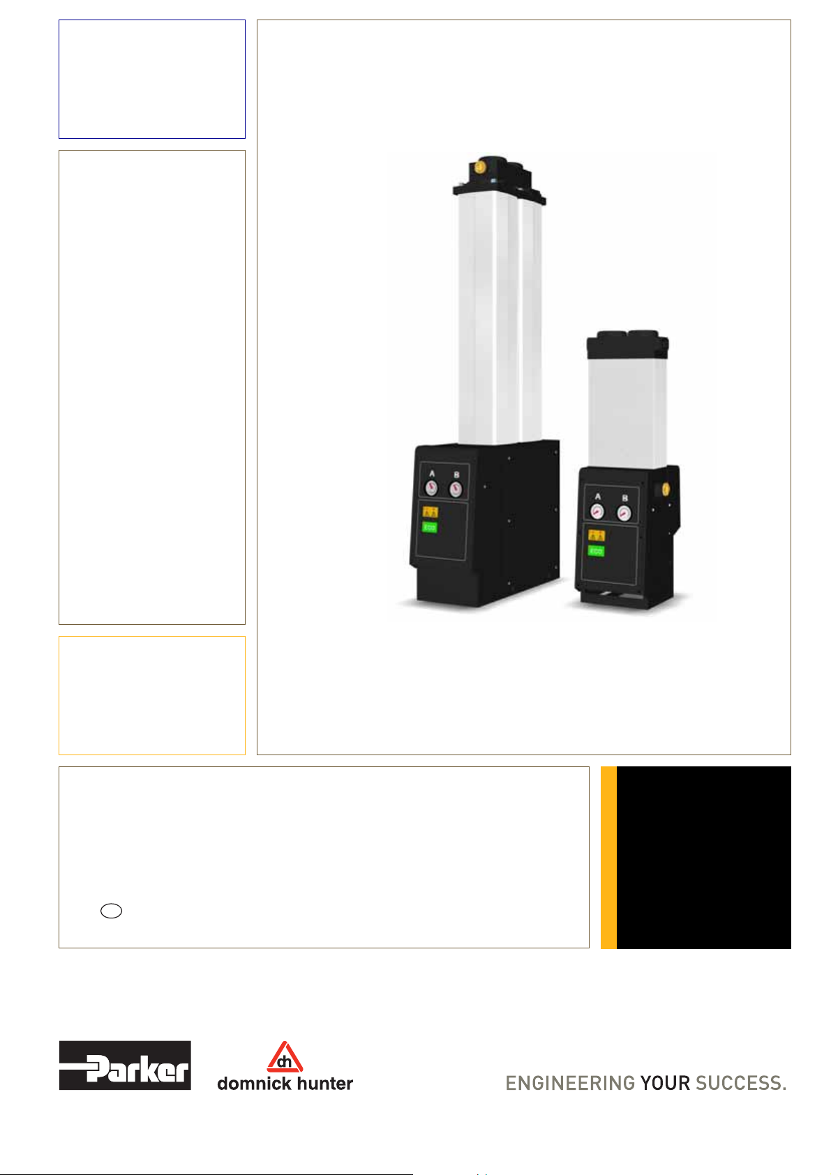
Medical Air Dryer
DME012-RX - DME080-RX
User Guide
Original Language
aerospace
climate control
electromechanical
filtration
fluid & gas handling
hydraulics
pneumatics
process control
sealing & shielding
Page 2

Page 3

DME012-RX - DME080-RX
Contents
1. Safety Information 4
1.1 Markings and symbols 5
1.2 Hazardous Substances 5
2. Description 6
2.1 Technical Specification 6
2.1.1 Dimensions 8
2.2 Unpacking the equipment 9
2.3 Overview of the equipment 10
3. Installation & Commissioning 11
3.1 Locating the equipment 11
3.2 Mechanical Installation 12
3.3 Electrical Installation 12
3.3.1 Mains supply 12
3.3.2 Hygrometer relay 13
4. Operating the equipment 14
4.1 Overview of Controls 14
4.2 Starting the equipment 14
Dewpoint Dependent Switching (DDS) 14
4.3 Stopping the equipment 14
5. Servicing 15
5.1 Cleaning 15
5.2 Service Intervals 15
5.3 Service Kits 16
5.4 Service Record 17
6. Troubleshooting guide 18
3
Page 4

DME012-RX - DME080-RX
1. Safety Information
Important: Do not operate this equipment until the safety information and instructions in this user guide have been read and understood by all
personnel concerned.
Only competent personnel trained, qualified, and approved by domnick hunter should perform commissioning, service and repair
procedures.
Use of the equipment in a manner not specified within this user guide may impair safety and invalidate your warranty.
When handling, installing or operating this equipment, personnel must employ safe engineering practices and observe all related
regulations, health & safety procedures, and legal requirements for safety.
Ensure that the equipment is depressurised and electrically isolated, prior to carrying out any of the scheduled maintenance instructions specified
within this user guide.
Most accidents that occur during the operation and maintenance of machinery are the result of failure to observe basic safety rules and procedures. Accidents can be avoided by recognising that any machinery is potentially hazardous.
domnick hunter can not anticipate every possible circumstance which may represent a potential hazard. The warnings in this manual cover the
most known potential hazards, but by definition can not be all-inclusive. If the user employs an operating procedure, item of equipment or a method
of working which is not specifically recommended by domnick hunter the user must ensure that the equipment will not be damaged or become
hazardous to persons or property.
Should you require an extended warranty, tailored service contracts or training on this equipment, or any other equipment within the
domnick hunter range, please contact your local domnick hunter office.
Details of your nearest domnick hunter sales office can be found at: www.domnickhunter.com
4
Page 5
DME012-RX - DME080-RX
1.1 Markings and symbols
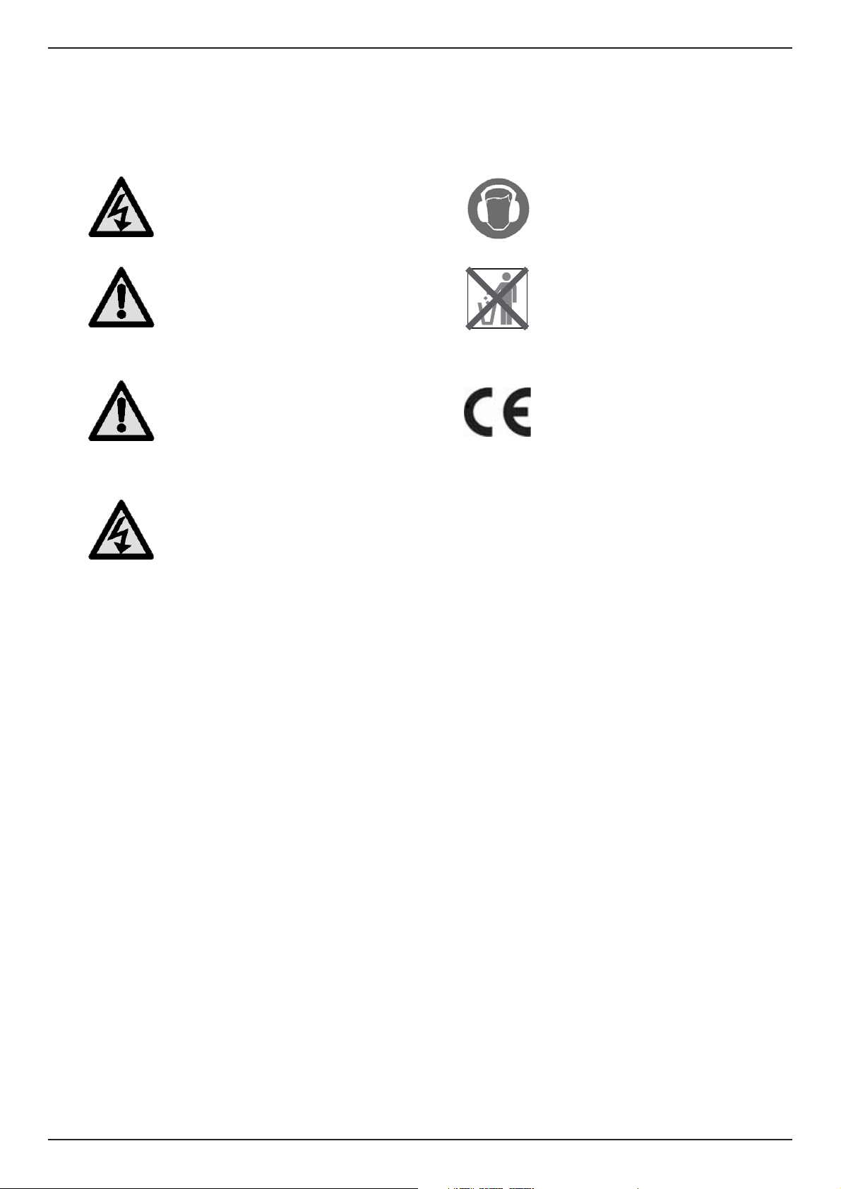
The following markings and international symbols are used on the equipment and within this user guide:
Warning
Caution
Warning
Risk of electric shock.
Highlights actions or procedures which,
if not performed correctly, may lead to
personal injury or death.
Highlights actions or procedures which,
if not performed correctly, may lead to
damage to this equipment.
Highlights actions or procedures which,
if not performed correctly, could lead to
electric shock.
Wear ear protection.
When disposing of old parts always
follow local waste disposal regulations
Conformité Européenne
1.2 Hazardous Substances
The columns are filled with a powerful desiccant material which will dry out the atmosphere, eyes, nose, and mouth if exposed.
The columns should only be opened and the desiccant changed by domnick hunter trained, qualified and approved engineer.
5
Page 6

DME012-RX - DME080-RX
2. Description
domnick hunter desiccant dryers are designed to remove moisture vapour from compressed air.
The dryer comprises of an inlet and outlet manifold joined together by an aluminium column. The column has two internal chambers filled with
desiccant material. During operation one chamber is on-line (drying), whilst the opposite chamber is regenerating. This process is known as
Pressure Swing Adsorption (PSA).
Pressure Swing Adsorption (PSA)
A small percentage of dried air is taken from the dryer output flow and is used to regenerate the saturated chamber by expanding the dried air from
line pressure to atmospheric pressure. During this process, the moisture is physically removed from the regenerating chamber and vented to
atmosphere through the exhaust silencers.
Dewpoint Dependent Switching (DDS)
DDS will adjust the dryer’s cycle in line with the moisture loading placed upon it, by constantly monitoring the processed air moisture
content.
6
Page 7
DME012-RX - DME080-RX
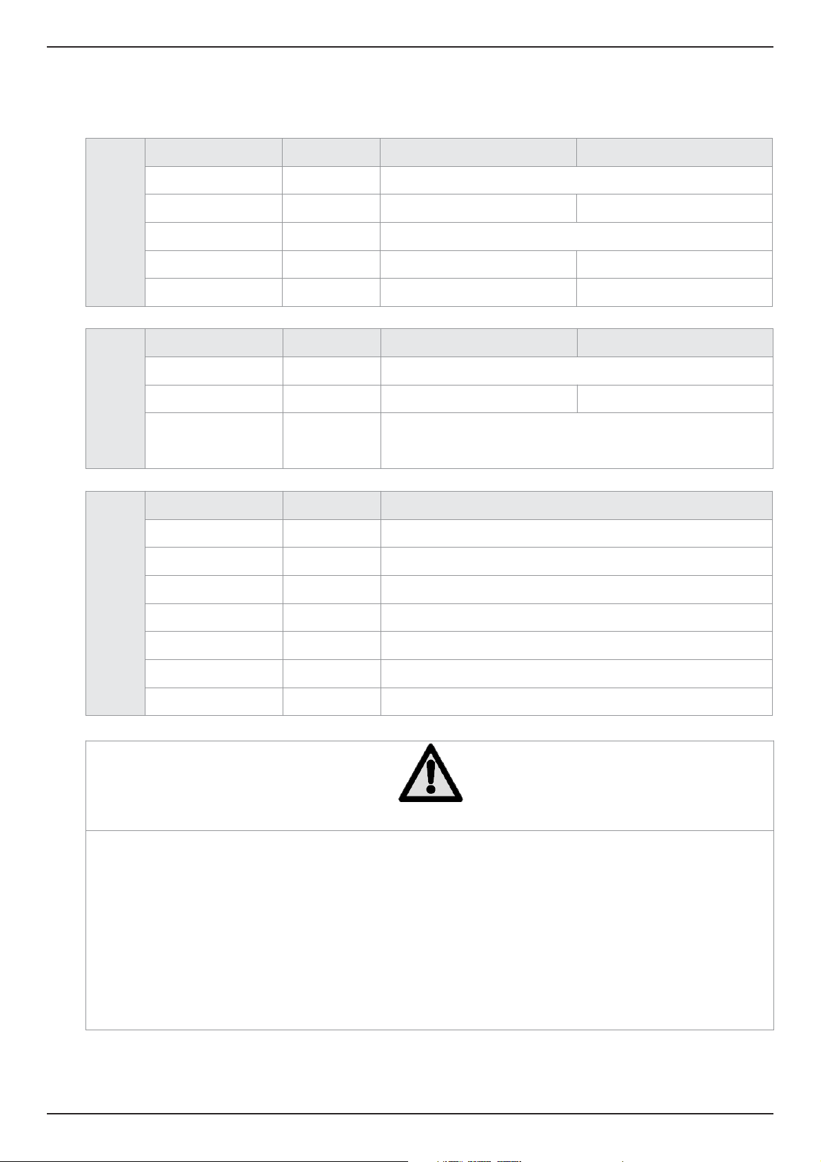
2.1 Technical Specification
This specification is valid when the equipment is located, installed, operated, and maintained as specified within this user guide.
Parameter Units DME012-RX - DME040-RX DME050-RX - DME080-RX
Minimum Inlet Pressure
Maximum Inlet Pressure
Specific
Inlet Temperature
Inlet Connection NPT Inches 3/4” 1”
Outlet Connection NPT Inches 3/4” 1”
bar g
(psi g / MPa g)
bar g
(psi g / MPa g)
ºC
(ºF)
16
(232 / 1.6)
Parameter Units DME012-RX - DME040-RX DME050-RX - DME080-RX
Supply Voltage V ac 110V ac 50/60Hz ± 10%
Power W 52 30
Electrical
Fuse mA
500 (230v Supply)
1000 (110v Supply)
5 x 20mm time delay “T”
4
(58 / 0.4)
5 – 50
41 - 122
13
(188 / 1.3)
Parameter Units DME012-RX - DME080-RX
Temperature
Humidity -
IP Rating - IP65 / >NEMA 13
Pollution Degree - 2
Environmental
Installation Category - II
Altitude
Noise dB(A) <75dBA
oC
(oF)
m
(ft)
2 – 45
35 - 113
50% @ 40ºC
(80% MAX ≤ 31ºC)
< 2000
(6562)
Caution
Before continuing with the installation and commissioning of this equipment:
Ensure that it is correctly sized for the inlet pressure, taking into consideration the pressure drop caused by the valves, pipes and
filters within the system. Allowance should be made for purge air loss. The dryer should be typically sized at 1 bar (14 psi) 0.1MPa
below nominal compressor output pressure.
The purge air flow is factory set for 6 bar g (87 psi g) minimum system pressure. Should the minimum supply pressure be lower
than this figure the purge air flow must be reset in order to maintain the specified dewpoint.
Ensure that it is correctly sized for inlet temperature to meet the dewpoint specified.
Ensure that the electrical supply voltage and frequency meet the requirements detailed within this specification and on the
equipment rating plate.
7
Page 8
DME012-RX - DME080-RX
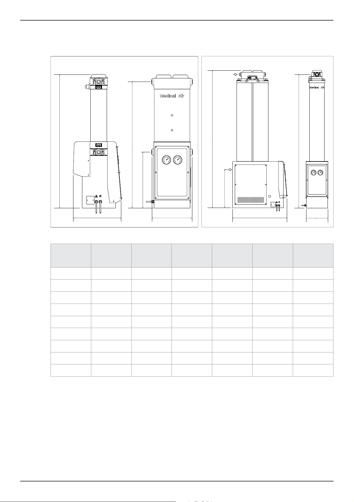
2.1.1 Dimensions
DME012-RX - DME040-RX
A
HYGROMETER
110VAC
DEWPOINT
POWER
RELAY
SUPPLY
B
DME050-RX - DME080-RX
D
E
C
A
E
110VAC
POWER
SUPPLY
B
D
HYGROMETER
DEWPOINT
RELAY
C
Model
DME012-RX
DME015-RX
DME020-RX
DME025-RX
DME030-RX
DME040-RX
DME050-RX
DME060-RX
DME080-RX
A
mm
(inches)
837
(32.9)
1003
(39.5)
1168
(46.0)
1333
(52.5)
1499
(59.0)
1747
(68.8)
1433
(56.4)
1599
(62.9)
1847
(72.7)
B
mm
(inches)
302
(11.9)
302
(11.9)
302
(11.9)
302
(11.9)
302
(11.9)
302
(11.9)
566
(22.3)
566
(22.3)
566
(22.3)
C
mm
(inches)
284
(11.2)
284
(11.2)
284
(11.2)
284
(11.2)
284
(11.2)
284
(11.2)
220
(8.7)
220
(8.7)
220
(8.7)
D
mm
(inches)
794
(31.26)
960
(37.8)
1125
(44.29)
1290
(50.79)
1456
(57.32)
1704
(67.09)
1390
(54.72)
1556
(61.25)
1804
(71.02)
E
mm
(inches)
352
(13.86)
352
(13.86)
352
(13.86)
352
(13.86)
352
(13.86)
352
(13.86)
395
(15.55)
395
(15.55)
395
(15.55)
Weight
Kg
(lbs)
32
(70)
37
(81)
42
(92)
47
(103)
52
(114)
60
(132)
80
(176)
90
(198)
104
(229)
8
Page 9
DME012-RX - DME080-RX
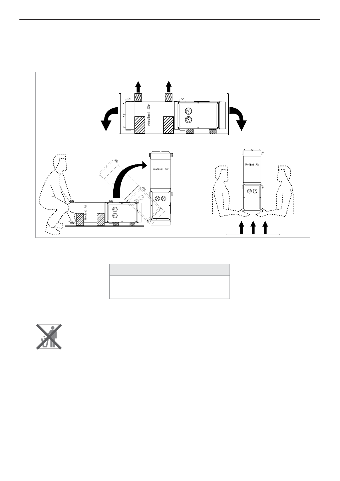
2.2 Unpacking the equipment
It is recommended that the equipment is moved into position before removing the packaging.
Remove the equipment from its packaging using the illustrations shown below for guidance and check that it has not been damaged in
transit.
The following items have been included with your equipment:
Description Qty
DME-RX Dryer 1
Dryer Test Certificate 1
If any items are missing or damaged please contact your local domnick hunter office.
9
Page 10
DME012-RX - DME080-RX
A
B
ECO
A
B
ECO
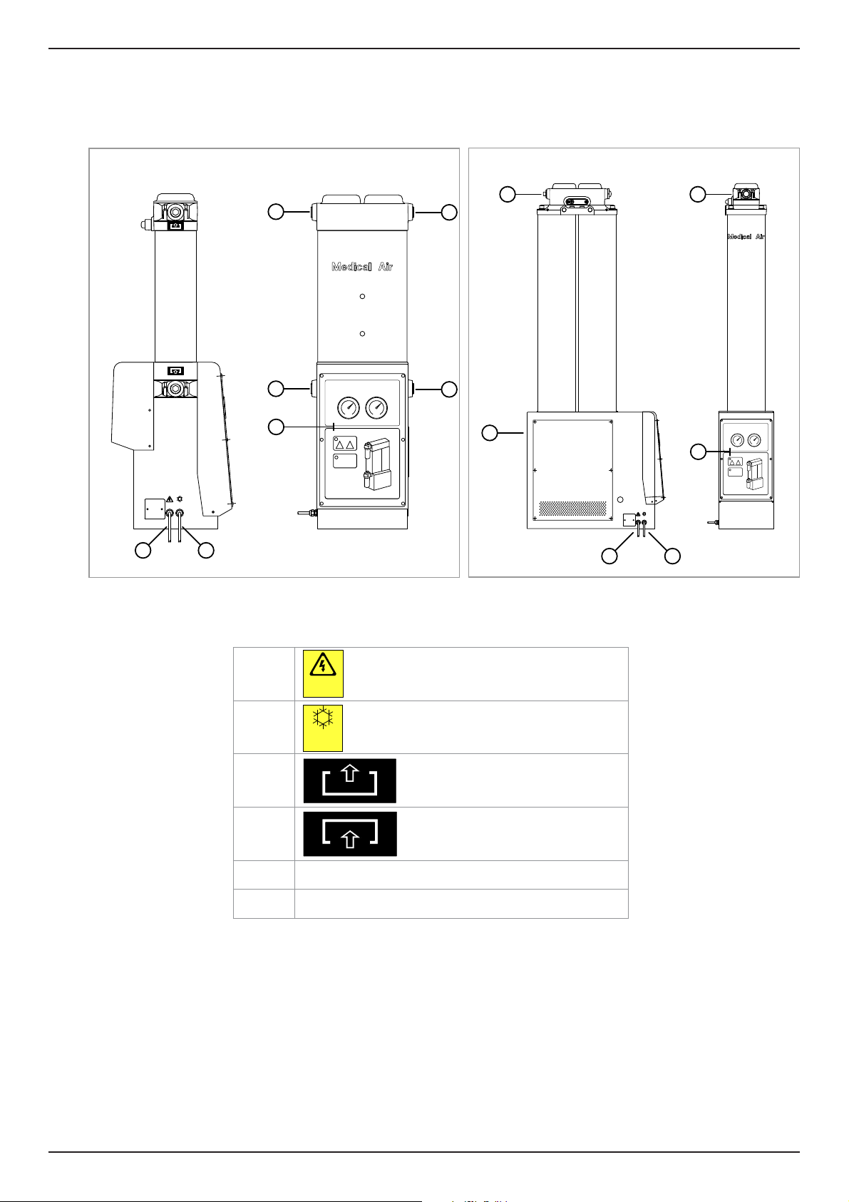
2.3 Overview of the equipment
Referring to diagram below, the major parts of the dryer are as follows:
DME012-RX - DME040-RX
110VAC
HYGROMETER
POWER
DEWPOINT
SUPPLY
RELAY
12
DME050-RX - DME080-RX
3
3
4
B
A
5
ECO
3
4
4
110VAC
HYGROMETER
POWER
DEWPOINT
SUPPLY
RELAY
6
B
A
5
ECO
12
1 Mains Supply Cable
2 Hygrometer Relay Cable
110VA C
POWER
SUPPLY
HYGROMETER
DEWPOINT
RELAY
3 Dryer Outlet
4 Dryer Inlet
5 Dryer Status Indicators
6 Outlet Sight Glass
10
Page 11
DME012-RX - DME080-RX
A
B
ECO
A
B
ECO
3. Installation & Commissioning
Only competent personnel trained, qualified, and approved by domnick hunter should perform installation,
commissioning and service procedures.
Warning
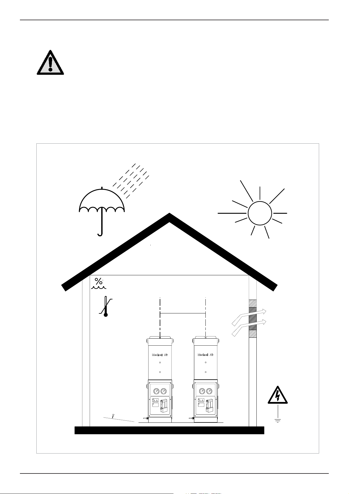
3.1 Locating the equipment
Identify a suitable location for the equipment taking into consideration the minimum space requirements for maintenance and lifting
equipment as shown in the diagram below. When considering the final location of the equipment take into account the noise generated
when in use.
The dryer can be free standing or secured to the floor via the fastener points provided in the base.
50% @ 40oC
(80% MAX ≤ 31oC)
+45oC
+5oC
±2°
500 CRS
B
B
A
ECO
A
ECO
11
Page 12
DME012-RX - DME080-RX
1
2
3.2 Mechanical Installation
The Dewpoint Dependent Switching (DDS) system requires a sampling point to be inserted into the piping at the outlet of the dryer.
It is important to ensure that all piping materials are suitable for the application, clean and debris free. The diameter of the pipes must be
sufficient to allow unrestricted inlet air supply to the equipment and outlet gas / air supply to the application.
When routing the pipes ensure that they are adequately supported to prevent damage and leaks in the system.
All components used within the system must be rated to at least the maximum operating pressure of the equipment. It is
recommended that the system be protected with suitably rated pressure relief valves.
A by-pass line may be installed into the system to provide a constant air supply during maintenance.
The by-pass line will allow untreated air to pass to the application and should only be used when the dryer has
been shut down.
Caution
3.3 Electrical Installation
A fully qualified electrical engineer must undertake all electrical work in accordance with local regulations
Warning
3.3.1 Mains supply
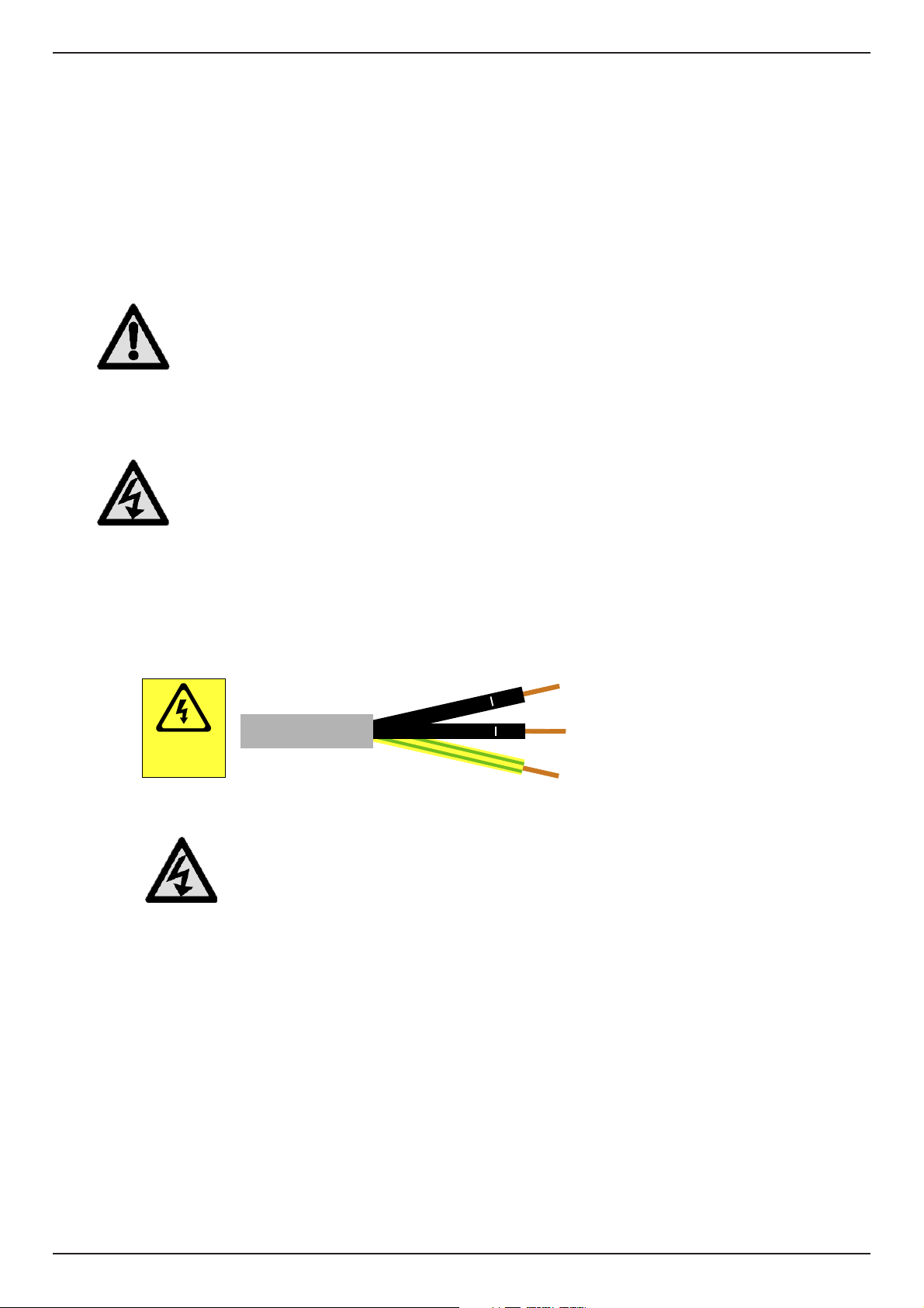
The dryer is supplied with a 3 core non-detachable mains supply cable as identified below.
110 VAC
POWER
SUPPLY
The Green / Yellow cconductor of the 3 core cable must be bonded to earth (ground)
Warning
LIVE
NEUTRAL
EARTH / GROUND
12
Page 13
DME012-RX - DME080-RX
1
2
HYGROMETER
DEWPOINT
RELAY
The equipment should be connected to the electrical supply through a switch or circuit breaker. This device should be clearly and indelibly
marked as the disconnecting device for the equipment and located in close proximity to the equipment and be easily accessible to the
operator.
Overcurrent protection must be fitted as part of the building installation. This protection should be selected in accordance with local and
national code regulations and based upon the technical data supplied for this equipment.
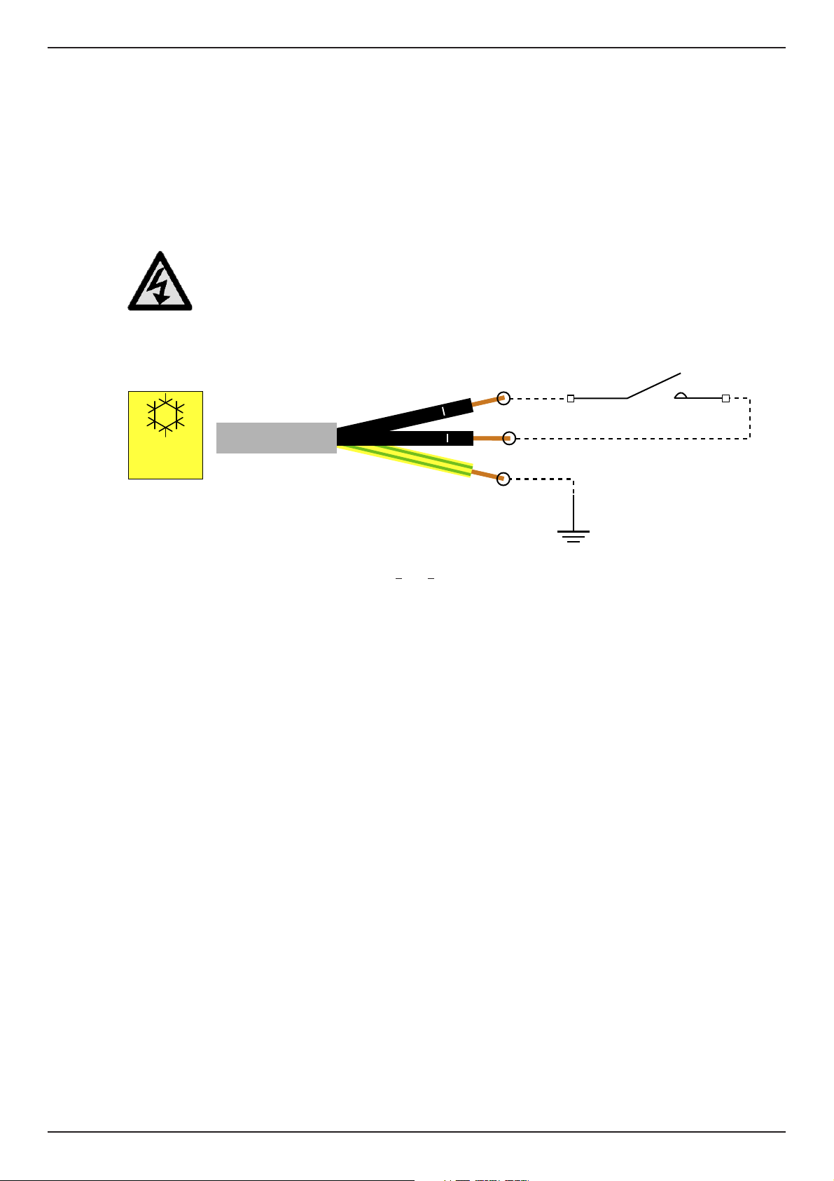
3.3.2 Hygrometer relay
The dryer is supplied with a 3 core non-detachable hygrometer relay cable as identified below.
The mains supply cable and hygrometer relay cables are clearly identified at the cable gland. Ensure that
the correct cable is selected prior to continuing the installation
Warning
For correct operation of the DDS system, conductors 1
When in operation, the contacts should close when the dewpoint reaches the set point and remain closed until the moisture
content rises above the set point.
Note: The dryer has an internal moisture over-ride which has been factory set at 30 minutes. This means that the dryer will revert
to normal operation after 30 minutes regardless of the dewpoint.
and 2 should be connected across a set of volt free contacts as shown.
13
Page 14
DME012-RX - DME080-RX
4. Operating the equipment
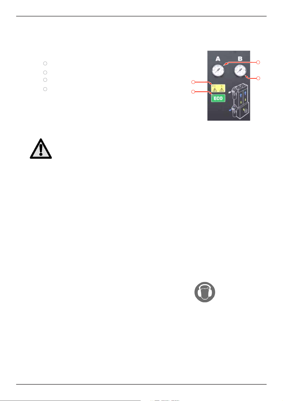
4.1 Overview of Controls
The facia of the dryer consists of indicators only as follows:
1
Power “ON” Indicator
2
ECO (DDS) Indicator
3
Column A Pressure Gauge
4
Column B Pressure Gauge
4.2 Starting the equipment
Start-up should be undertaken by a domnick hunter trained, qualified and approved service engineer.
3
4
1
2
Warning
1. Ensure that the isolation valves on the inlet and the outlet of the dryer are closed.
2. Connect the electrical supply to the dryer and verify that the Power On indicator is illuminated.
3. Slowly open the isolation valve on the inlet of the dryer. Verify that there are no leaks.
4. Check that the system pressure relief valve is closed.
5. Test the condensate drains of the filters and verify that they are discharging correctly into a suitable collection vessel.
6. When the dryer is pressurised to full system pressure, slowly open the outlet isolation valve.
If a bypass line has been fitted, close the bypass valve.
7. Verify that the column pressure gauges are cycling between zero and full system pressure every three minutes.
The dryer is fully automatic and requires no user intervention until shut-down.
Dewpoint Dependent Switching (DDS)
If the dryer is producing air at a better dewpoint than specified the DDS system will hold the dryer at a point just before the changeover
occurs. The green “ECO” LED will illuminate and both pressure gauges will read full system pressure.
The dryer will resume normal operation the instant the DDS system monitors a fall in dewpoint to the specified level.
4.3 Stopping the equipment
1. Close the isolation valve on the outlet followed by the isolation valve at the inlet.
If a bypass line has been fitted, simultaneously open the bypass valve.
2. De-pressurise the dryer by venting through the drain ball valve on the outlet dust filter.
Note: The drain valve should be opened gradually.
3. Disconnect the electrical supply to the dryer.
14
Page 15
DME012-RX - DME080-RX
5. Servicing
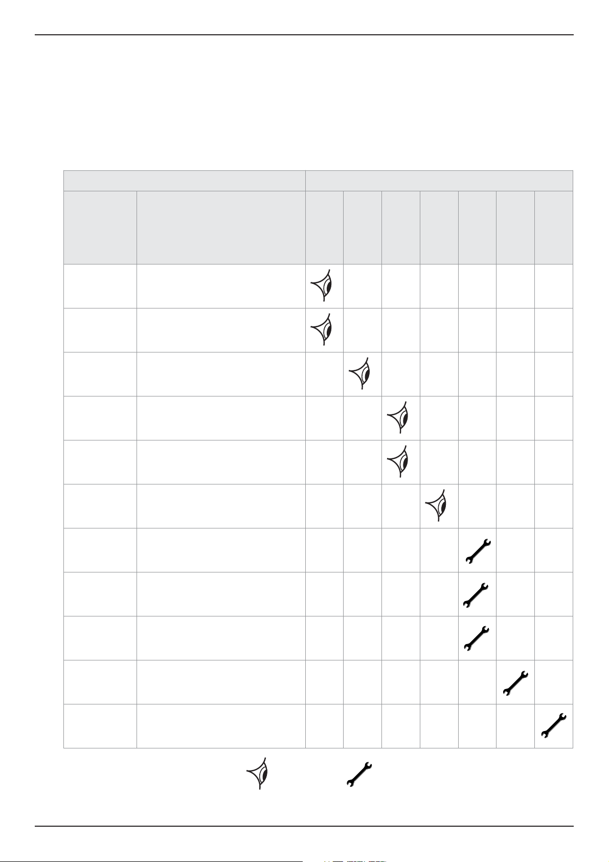
The recommended Service procedures identified in table 5.2 and all other repair and calibration work should be undertaken by a domnick
hunter trained, qualified and approved engineer.
5.1 Cleaning
Clean the equipment with a damp cloth only and avoid excessive moisture around any electrical sockets. If required you may use a mild
detergent, however do not use abrasives or solvents as they may damage the warning labels on the equipment.
5.2 Service Intervals
Description of Service Requirement Typical Recommended Service Interval
Component Operation
Daily
Dryer Check POWER ON indicator is illuminated. - - - - - -
Dryer
Dryer Check for air leaks. - - - - - -
Dryer
Dryer
Dryer Check for cyclic operation. - - - - - -
Check STATUS / FAULT indicators located
on the control panel.
Check the pressure gauges during purging
for excessive back pressure.
Check the condition of electrical supply
cables and conduits.
- - - - - -
- - - - - -
Weekly
- - - - - -
3 Months
6 Months
12 Months
24 Months
30 Months
Dryer
Filtration
Dryer Replace / Calibrate dewpoint transmitter - - - - - -
Dryer
Dryer
Replace the active exhaust silencers
Recommended Service A
Replace the inlet, outlet and control air
filters, and service drains.
Replace the valve seats and seals.
Recommended Service D
Replace the Desiccant.
Recommended Service E
Check
- - - - - -
- - - - - -
- - - - - -
- - - - - -
Replace
Table 5.2
15
Page 16
DME012-RX - DME080-RX
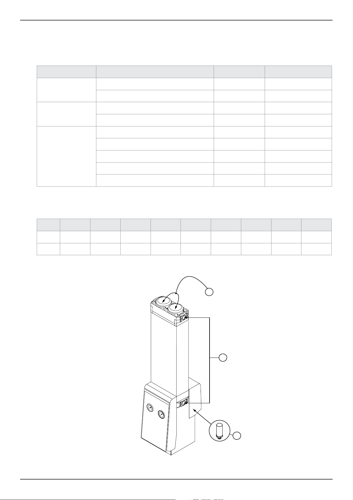
5.3 Service Kits
Service Kit Description Kit No Quantity
A – Silencer Service
D – Valve Service
Kit: Exhaust Silencer DME012-RX - DME040-RX 608233670 1
Kit: Exhaust Silencer DME050-RX - DME080-RX 608330001 1
Kit: Valve Overhaul DME012-RX - DME040-RX 608330006 1
Kit: Valve Overhaul DME050-RX - DME080-RX 608330007 1
AA 11.2 Litre Bag 608203661 See table below
Kit: Column Seals DME012-RX - DME040-RX 608203733 1
E – Desiccant Service
DME012-RX DME015-RX DME020-RX DME025-RX DME030-RX DME040-RX DME050-RX DME060-RX DME080-RX
Dryfil AA 1 1 2 2 2 2 3 4 5
Seals 1 1 1 1 1 1 1 1 1
Kit: Column Seals DME050-RX - DME080-RX 608330010 1
Snow storm filler DME012-RX - DME040-RX 608200622 1
Snow storm filler DME050-RX - DME080-RX 608201051 1
E
16
D
A
Page 17
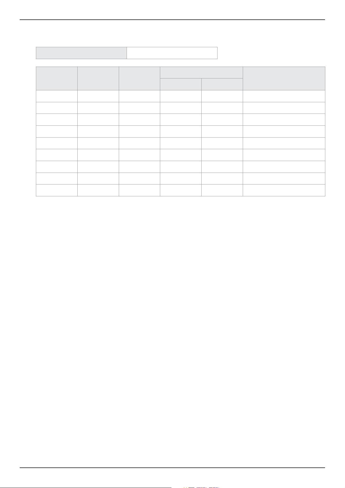
DME012-RX - DME080-RX
5.4 Service Record
Date of Commissioning
Service
(Hours)
4,000
8,000
16,000
20,000
24,000
28,000
32,000
36,000
40,000
Hours
Shown
Date
Serviced By
Comments / Observations
Print Initials
17
Page 18

DME012-RX - DME080-RX
6. Troubleshooting guide
In the unlikely event that a problem occurs on the equipment, this troubleshooting guide can be used to identify the probable cause and
remedy.
Troubleshooting should only be attempted by competent personnel. All major repair, and calibration work should
be undertaken by a domnick hunter trained, qualified and approved engineer.
Warning
Problem Indication Probable Cause Remedy
Poor dewpoint Crystals go clear in the outlet
sight glass (DME040 - 080-RX
Models only)
Entrained Water
Excessive air flow demand
Check pre-filtration drains.
Check actual flow against rated flow of
dryer
Check for recent additions to air system
Inlet pressure too low
Excessive inlet air
temperature
Insufficient purge air flow
Exhaust silencers blocked
Contaminated desiccant
Electrical fault Flashing Yellow LED Hardware fault
High differential pressure Pressure gauges Excessive outlet flow Check and regulate air demand
Failure to purge
Outlet air flow stops
No depressurisation and poor
dewpoint
Downstream pressure drops.
Yellow LED “OFF”
Purge valve blocked or shut.
Exhaust silencers blocked.
Electrical fault.
Blown fuse in plug.
Check against technical specification
Check against technical specification
Factory set for 6 bar g (87 psig) system
pressure.
domnick hunter trained personnel to
adjust
Change by domnick hunter trained
personnel
Eliminate source of contamination.
Desiccant change by domnick hunter
trained personnel
Contact domnick hunter customer
services
domnick hunter trained personnel to
adjust.
Change by domnick hunter trained
personnel
domnick hunter trained personnel to
adjust.
Change by domnick hunter trained
personnel
Constant depressurisation Erratic air flow from exhaust Damaged valve.
18
Change by domnick hunter trained
personnel
Page 19

Declaration of Conformity EN
Parker Hannifin ltd, Industrial division
Dukesway, TVTE, Gateshead, Tyne & Wear, NE11 0PZ. UK
DME012-RX, DME015-RX, DME020-RX, DME025-RX, DME030-RX, DME040-RX, DME050-RX, DME060-RX, DME080-RX
Directives 97/23/EC
Adsorption Dryer
2006/95/EC
2004/108/EC
93/68/EEC, 92/31/EEC
Standards used EN 61010-1 : 2001
PED Assessment Route : B & D
EC Type-examination Certificate: LDS 9900792/5
Notified body for PED: Lloyds Register Verification
Authorised Representative Derek Bankier
Divisional Quality Manager
Parker Hannifin ltd, Industrial division
EN 61000-6-1 : 2005EN 61000-6-2 : 2001
EN 61000-6-3 : 2001EN 61000-6-4 : 2001
EN 61000-3-2 : 2000
EN 61000-3-3 : 1995
Generally in accordance with ASMEVIII Div 1 : 2004.
71 Fenchurch St. London
EC3M 4BS
Declaration
I declare that as the authorised representative, the above information in relation to the supply / manufacture of this product, is
in conformity with the standards and other related documents following the provisions of the above Directives.
Signature: Date: 22/01/2010
Declaration Number: 0028/220110
Page 20

Page 21

AE – UAE, Dubai
Tel: +971 4 8127100
[email protected]
AR – Argentina, Buenos Aires
Tel: +54 3327 44 4129
AT – Austria, Wiener Neustadt
Tel: +43 (0)2622 23501-0
[email protected]
AT – Eastern Europe,
Wiener Neustadt
Tel: +43 (0)2622 23501 900
[email protected]
A
U – Australia,Castle Hill
Tel: +61 (0)2-9634 7777
AZ – Azerbaijan, Baku
Tel: +994 50 2233 458
[email protected]
BE/LU – Belgium, Nivelles
Tel: +32 (0)67 280 900
[email protected]
BR – Brazil, Cachoeirinha RS
Tel: +55 51 3470 9144
BY – Belarus, Minsk
Tel: +375 17 209 9399
[email protected]
CA – Canada, Milton, Ontario
Tel: +1 905 693 3000
CH – Switzerland, Etoy
Tel: +41 (0) 21 821 02 30
[email protected]
CL – Chile, Santiago
Tel: +56 2 623 1216
CN – China, Shanghai
Tel: +86 21 5031 2525
CZ – Czech Republic, Klecany
Tel: +420 284 083 111
[email protected]
DE – Germany, Kaarst
Tel: +49 (0)2131 4016 0
[email protected]
DK – Denmark, Ballerup
Tel: +45 43 56 04 00
[email protected]
ES – Spain, Madrid
Tel: +34 902 33 00 01
[email protected]
FI – Finland, Vantaa
Tel: +358 (0)20 753 2500
parker.[email protected]
FR – France, Contamine s/Arve
Tel: +33 (0)4 50 25 80 25
[email protected]
GR – Greece, Athens
Tel: +30 210 933 6450
[email protected]
HK – Hong Kong
Tel: +852 2428 8008
HU – Hungary, Budapest
Tel: +36 1 220 4155
[email protected]
IE – Ireland, Dublin
T
el: +353 (0)1 466 6370
IN – India, Mumbai
Tel: +91 22 6513 7081-85
IT – Italy, Corsico (MI)
Tel: +39 02 45 19 21
[email protected]
JP – Japan, Tokyo
Tel: +(81) 3 6408 3901
KR – South Korea, Seoul
Tel: +82 2 559 0400
KZ – Kazakhstan, Almaty
Tel: +7 7272 505 800
[email protected]
LV – Latvia, Riga
Tel: +371 6 745 2601
[email protected]
MX – Mexico, Apodaca
Tel: +52 81 8156 6000
MY – Malaysia, Shah Alam
Tel: +60 3 7849 0800
NL – The Netherlands,
Oldenzaal
Tel: +31 (0)541 585 000
[email protected]
NO – Norway, Ski
Tel: +47 64 91 10 00
[email protected]
NZ – New Zealand,
Mt Wellington
Tel: +64 9 574 1744
PL – Poland, Warsaw
Tel: +48 (0)22 573 24 00
[email protected]
PT – Portugal, Leca da Palmeira
Tel: +351 22 999 7360
[email protected]
RO – Romania, Bucharest
Tel: +40 21 252 1382
[email protected]
RU – Russia, Moscow
Tel: +7 495 645-2156
[email protected]
SE – Sweden, Spånga
Tel: +46 (0)8 59 79 50 00
[email protected]
SG – Singapore
Tel: +65 6887 6300
SK – Slovakia, Banská Bystrica
Tel: +421 484 162 252
[email protected]
SL – Slovenia, Novo Mesto
Tel: +386 7 337 6650
[email protected]
TH – Thailand, Bangkok
Tel: +662 717 8140
TR – Turkey, Istanbul
Tel: +90 216 4997081
[email protected]
TW – Taiwan, Taipei
Tel: +886 2 2298 8987
UA – Ukraine, Kiev
Tel +380 44 494 2731
[email protected]
UK – United Kingdom,
Warwick
Tel: +44 (0)1926 317 878
[email protected]
US – USA, Cleveland
Tel: +1 216 896 3000
VE – Venezuela, Caracas
Tel: +58 212 238 5422
ZA – South Africa,
Kempton Park
Tel: +27 (0)11 961 0700
[email protected]
Parker Worldwide
European Product Information Centre
Free phone: 00 800 27 27 5374
(from AT, BE, CH, CZ, DE, DK, ES, FI, FR, IE,
IT, NL, NO, PL, PT, RU, SE, UK, ZA)
A division of Parker Hannifin Corporation Copyright Parker Hannifin ltd 2010
Publication Reference: 176034100 01/10 Rev.000
Parker Hannifin ltd
Industrial division
Dukesway, Team Valley Trading Est
Gateshead, Tyne and Wear
England NE11 0PZ
Tel: +44 (0) 191 402 9000
Fax: +44 (0) 191 482 6296
www.domnickhunter.com
 Loading...