

Page 1
P OWER CONNECTIONS
B EFORE YOU STAR T
This document covers the steps necessary
for a basic start up of the DC590+DRV drive.
Drive start ups should be performed b
y
qualified electrical technicians who are
familiar with DC drives and their applications. For detailed safety, installation, advanced features and applications on the
590+, refer to the Product Manual.
Ensure that all local electric codes are met
while installing the drive. Check that all live
parts are covered to protect against electric
shock and that unexpected rotation of the
motor will not result in bodily harm or injury.
This document expects that the drive is
already installed in its intended location and
that all relevant installation procedures
have been followed. Please ensure that the
drive has adequate ventilation so that ambient temperature does not exceed 45°C
(112°F) under normal operating conditions.
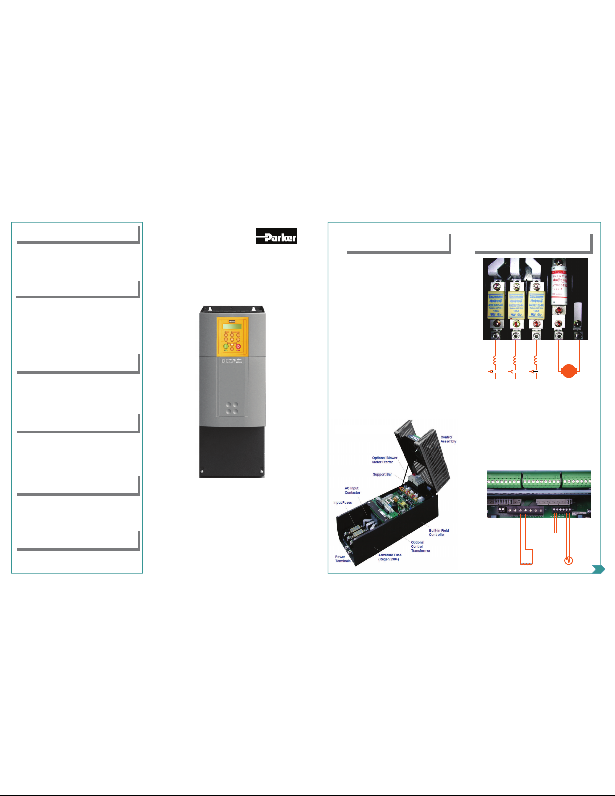
To access the bottom layer, slide off the
bottom terminal cover and unfasten the two
retaining screws. Hinge the plastic body
upwards and engage the support bar.
• 3-phase supply to L1, L2, L3
• Motor armature to A+, A-
• Motor fields to F+, F-
• Motor thermistor to Th1, Th2
• Control supply to L, N. Check
drive nameplate for correct aux
voltage supply rating
• Blower to BL1, BL2, BL3, if fitted
thermistor
thermistor
control power
control power
field
field
M
M
armature
armature
3 phase powe
r
3 phase power
Frame 2 (165A)
C ONFIGURE I/O
Under MENU LEVEL\SYSTEM\CONFIGURE I/O, you
may connect and disconnect internal block diagram connections, to use special functions like PID, winder blocks,
diameter block, etc., and to tag analog and digital I/O to
selected points inside the drive to suit your application
needs.
S ERIAL LINKS
Under MENU LEVEL\SERIAL LINKS, you may access
parameters related to Techboxes, the system port (P3),
and all the PNO configuration parameters.
S ETUP PARAMETERS
Under MENU LEVEL\SETUP PARAMETERS, there are
several submenus where you can enter setup parameters. They are:
Ramps, Auxiliary I/O, Op Station, Jog/Slack, RaiseLower, Preset Speeds, Special Blocks, Field Control,
Current Profile, Inverse Time, Stop Rates, Calibration,
Inhibit Alarms, Current Loop, Speed Loop, Standstill,
Setpoint sum 1.
Under MENU LEVEL\PASSWORD, you may enter a
password to protect against unauthorized access to the
drive setup parameters. Refer to the 590+ product manual
for details.
A LARMS & PASSWORD
Under MENU LEVEL\ALARM STATUS, you may view
the active and last alarm status.
A RMATURE AUTOTUNE
• In the configure drive menu, set Autotune to ARM
•
On the keypad, press L/R for LOCAL mode
•
Ensure that the motor shaft is not allowed to rotate
•
Press RUN. Drive will begin autotuning the armature.
•
When the drive stops and no error message is displayed on the MMI,
the autotune was successful.
• Go to MENU LEVEL\SAVE PARAMETERS and save
your settings.
F IELD AUTOTUNE
• In the configure drive menu, set Autotune to FLD
•
On the keypad, press L/R for LOCAL mode
•
Press RUN. Drive will begin autotuning the field.
•
When the drive stops and no error message is displayed on the MMI,
the autotune was successful.
Parker Hannifin Corporation
SSD Drives Division
9225 Forsyth Park Drive
Charlotte, NC 28273 USA
www.SSDdrives.com
Main (704) 588-3246 Support (704) 602-6062
HA470388U200 Issue 6
DC590+ DRV
Series 2
Quick Start
Frame 2
165 amps
Page 2
P
P
P
OWER
OWER
OWER
O
O
O
N
N
N
R EFERENCE S EQUENCING
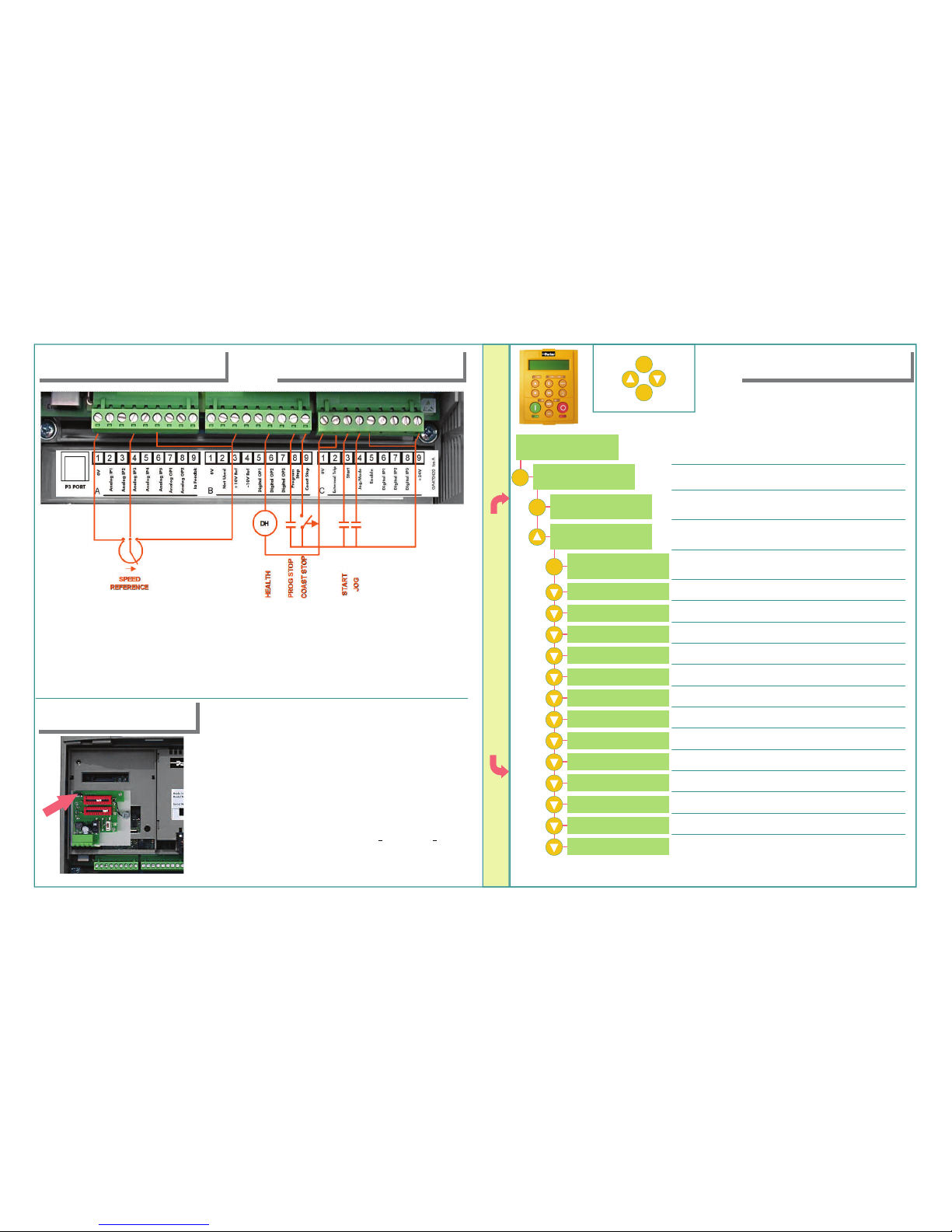
• Speed potentiometer across A1
(low), B3(high), A4(wiper) OR
• External 2-wire speed reference
between A1(-) and A4(+)
• Jumper A6 to B3
• E-Stop relay n.o. contact between B8, C9
• E-Stop relay n.o. TDD contact between B9, C9
• Jumper C1 and C2 if no external trip contact
• Jumper C5 and C9 for internal enable contact
• Start contact between C3 and C9
• Jog contact between C4 and C9
• Health relay coil (24V) between B6(+) and C1(-)
• Armature Voltage is the default speed feedback
mode and does not require a feedback card.
• Four feedback cards are available. Analog Tach,
encoder, acrylic microtach and glass microtach.
• Select the correct feedback card. Install it on the
feedback header, shown by the arrow in the figure.
Ensure all standoffs are securely snapped in place
• On the analog tach card, set switch settings in Units,
Tens and Hundred, corresponding to tachometer
output voltage at maximum speed
• DC Analog Tach: G3(+), G4(-). Set switch to DC
• AC Analog Tach: G1, G2. Set switch to AC
• Encoder: E1=0V, E2=+, E3,E4=A, A, E5,E6=B, B
• Microtach: C1=0V, C9=24V, F1=fiberoptic receive
S PEED FEEDBACK
C ALIBRATION
All calibration is done in software, through
the keypad.
M
E
ESCAPE ONE LEVEL
ENTER MENU
SCROLL
UP
SCROLL
DOWN
The DC590+ can also be calibrated using the programming tool software.
This is the power-up welcome screen
DIGITAL DC DRIVE
DC 4Q 34A
MENU LEVEL
DIAGNOSTICS
MENU LEVEL
CONFIGURE DRIVE
NOM MOTOR VOLTS
CONFIGURE DRIVE
CONFIGURE ENABLE
ARMATURE CURRENT
FIELD CURRENT
FLD. CTRL MODE
FLD. VOLTS RATIO
MAIN CURR.LIMIT
AUTOTUNE
SPEED FBK SELECT
ENCODER LINES
ENCODER RPM
ENCODER SIGN
SPD. INT TIME
SPD. PROP GAIN
DC 4Q 34A
MENU LEVEL
Press M. You are in MENU LEVEL, at DIAGNOSTICS
Press the M key to get to MENU LEVEL
Up arrow to get to CONFIGURE DRIVE menu
Press M and up arrow to ENABLE drive configuration
All 7 LEDs blink in Configuration mode. Press E when done
Enter rated motor armature current
Toggle between voltage and current modes
Enter desired current limit setting. Usually 100%
Change the polarity of the encoder signal
Speed loop integral gain
Speed loop proportional gain
Using the Up & Down arrows, enter rated motor voltage
Enter rated field current. Skip if field is in Voltage mode
If in voltage mode: Ratio = (field volts/AC supply)*100
Example: For a 300V field and 460V supply: Ratio = 300/460*100 = 65%
Leave this OFF. Autotune after calibration is complete
Choose from Armature Volts/Analog Tach/Encoder
Enter the pulses per rev. rating of the encoder
Enter the max speed here. Corresponds to 100% speed
• Set CONFIGURE ENABLE to DISABLE. The drive will display “CALIBRATING”
• Under MENU LEVEL/PARAMETER SAVE, press the M and UP to save your settings
M
M
M
 Loading...