

Page 1

EN
FRESIT
Breathing Air Module
BAM10 - BAM70
User Guide
Original Language
DE
aerospace
climate control
electromechanical
filtration
fluid & gas handling
hydraulics
pneumatics
process control
sealing & shielding
Page 2

Page 3

CONTENTS
1 Safety Information ........................................................................................................................................................................................1
1.1 Markings and Symbols ........................................................................................................................................................................2
2 Description ....................................................................................................................................................................................................3
2.1 Technical Specification........................................................................................................................................................................3
2.2 Approvals Compliance and Exemptions ............................................................................................................................................ 4
2.3 Materials of Construction ....................................................................................................................................................................5
2.4 Weights and Dimensions.....................................................................................................................................................................6
2.4.1 Module..........................................................................................................................................................................................6
2.4.2 Packaged Module.........................................................................................................................................................................6
2.5 Receiving and Inspecting the Equipment ..........................................................................................................................................7
2.5.1 Storage......................................................................................................................................................................................... 7
2.5.2 Unpacking ....................................................................................................................................................................................7
2.5.3 Lifting and Handling......................................................................................................................................................................7
2.6 Overview of the equipment..................................................................................................................................................................8
3 Installation and Commissioning..................................................................................................................................................................9
3.1 Recommended System Layout ...........................................................................................................................................................9
3.2 Locating the Equipment.......................................................................................................................................................................9
3.2.1 Environment .................................................................................................................................................................................9
3.2.2 Space Requirements.................................................................................................................................................................... 9
3.3 Mechanical Installation ......................................................................................................................................................................10
3.3.1 General Requirements ...............................................................................................................................................................10
3.3.2 Securing the Module ..................................................................................................................................................................10
3.3.3 Piping Connections ....................................................................................................................................................................10
3.4 Electrical Installation..........................................................................................................................................................................11
3.4.1 BAM Electrical Supply................................................................................................................................................................11
3.4.2 BAM Remote alarm indication.................................................................................................................................................... 11
3.4.3 CO Monitor Remote Alarm.........................................................................................................................................................12
4 Operating the Dryer ...................................................................................................................................................................................13
4.1 Overview of controls ..........................................................................................................................................................................13
4.1.1 Dryer Controls ............................................................................................................................................................................13
4.1.2 CO Analyser Controls.................................................................................................................................................................13
4.2 Starting the equipment ......................................................................................................................................................................14
4.3 Stopping and depressurising the equipment ..................................................................................................................................14
5 Service intervals .........................................................................................................................................................................................15
5.1 Preventative Maintenance Kits..........................................................................................................................................................16
6 Troubleshooting.......................................................................................................................................................................................... 20
7 Declaration of Conformity..........................................................................................................................................................................21
Page 4

Page 5

1 Safety Information
Do not operate this equipment until the safety information and instructions in this user guide have been read and understood by all
personnel concerned.
USER RESPONSIBILITY
FAILURE OR IMPROPER SELECTION OR IMPROPER USE OF THE PRODUCTS DESCRIBED HEREIN OR RELATED ITEMS CAN CAUSE
DEATH, PERSONAL INJURY AND PROPERTY DAMAGE.
This document and other information from Parker Hannifin Corporation, its subsidiaries and authorised distributors provide product or system
options for further investigation by users having technical expertise.
The user, through its own analysis and testing, is solely responsible for making the final selection of the system and components and assuring
that all performance, endurance, maintenance, safety and warning requirements of the application are met. The user must analyse all aspects of
the application, follow applicable industry standards, and follow the information concerning the product in the current product catalogue and in
any other materials provided from Parker or its subsidiaries or authorised distributors.
To the extent that Parker or its subsidiaries or authorised distributors provide component or system options based upon data or specifications
provided by the user, the user is responsible for determining that such data and specifications are suitable and sufficient for all applications and
reasonably foreseeable uses of the components or systems.
Only competent personnel trained, qualified, and approved by Parker Hannifin should perform installation, commissioning, service and repair
procedures.
Use of the equipment in a manner not specified within this user guide may result in an unplanned release of pressure, which may cause serious
personal injury or damage.
When handling, installing or operating this equipment, personnel must employ safe engineering practices and observe all related regulations,
health & safety procedures, and legal requirements for safety.
Ensure that the equipment is depressurised and electrically isolated, prior to carrying out any of the scheduled maintenance instructions specified
within this user guide.
Parker Hannifin can not anticipate every possible circumstance which may represent a potential hazard. The warnings in this manual cover the
most known potential hazards, but by definition can not be all-inclusive. If the user employs an operating procedure, item of equipment or a
method of working which is not specifically recommended by Parker Hannifin the user must ensure that the equipment will not be damaged or
become hazardous to persons or property.
Most accidents that occur during the operation and maintenance of machinery are the result of failure to observe basic safety rules and
procedures. Accidents can be avoided by recognising that any machinery is potentially hazardous.
Should you require an extended warranty, tailored service contracts or training on this equipment, or any other equipment within the Parker
Hannifin range, please contact your local Parker Hannifin office.
Details of your nearest Parker Hannifin sales office can be found at www.parker.com/dhfns
Retain this user guide for future reference.
1
Page 6

1.1 Markings and Symbols
The following markings and international symbols are used on the equipment or within this manual:
Caution, Read the User Guide. Wear ear protection
Risk of electric shock. Pressurised components on the system
Highlights actions or procedures which, if not performed
correctly, may lead to personal injury or death.
Highlights actions or procedures which, if not performed
correctly, may lead to damage to this product.
Highlights actions or procedures which, if not performed
correctly, could lead to electric shock.
Read the User Guide
Use a fork lift truck to move the dryer.
Remote control. The dryer may start automatically without
warning.
Conformité Européenne
When disposing of old parts always follow local waste
disposal regulations.
Waste electrical and electronic equipment should not be
disposed of with municipal waste.
2
Page 7

2 Description
2.1 Technical Specification
Flow Data
Model Pipe Size
BAM10
BAM20
BAM30
BAM40
BAM50
BAM70
Stated flows are for operation at 7 bar g (100 psi g / 0.7 MPa g) with reference to 20ºC, 1 bar a, 0% relative water vapour pressure.
G 2 113 6.8 408 240 90.4 5.4 326.4 192
G 2 170 10.2 612 360 136 8.2 489.6 288
G 2 213 12.8 765 450 170.4 10.2 612 360
G 2 283 17.0 1020 600 226.4 13.6 816 480
G 21/2 354 21 1275 750 283.2 16.8 1020 600
G 21/2 496 30 1785 1050 396.8 24 1428 840
L/s
Inlet Outlet
m3/min m3/hr
cfm L/s
m3/min m3/hr
Performance
Pressure Dewpoint
Dryer Model
o
All Models
ISO 8573-1 classifications apply when the dryer is installed with the filtration supplied
-40 -40 Class 2
(Standard)
C
o
F
Contaminants Units
Oil / Lubricant
mg/m
3
Ref.
Water ppm 7,913 24 67
Carbon Monoxide (CO) ppm 39 <0.01 5
Carbon Dioxide (CO2)
Oxygen (O2)
Nitrogen Oxides (NO + NO2)
Sulphur Dioxide (SO2)
o
Reference conditions: 20
C, 1 bar(a), dry. Compressed air conditions: 7 bar overpressure, 35oC
ppm 744 109 500
Vol. -% 20.9 20.9 20.4 - 21.4
ppm 13 1.8 2
ppm 7 <0.01 1
ISO 8573-1:2010
Water Classification
(Standard)
Inlet Challenge
(All Models)
11. 3 0.011
Outlet Levels
(All Models)
European
Pharmacopoeia
Operating Data
cfm
0.1
Model
All Models
Min Operating Pressure
Max Operating
bar g psi g bar g psi g
4 58 13 188.5 5 41 35 95
Pressure
Min Operating
Temperature
o
C
o
F
Electrical Data
BAM10 BAM20 BAM30 BAM40 BAM50 BAM70
Supply Voltage
Connection Type
Power
1
Fuse
1 Fuses are Anti surge (T) 250VAC, 5x20mm, HBC, Breaking capacity 1500A @250VAC, IEC 60127-2, UL/CSA Ceramic body.
90 - 264V 1PH 50/60Hz
Hard wired
21 W (Max)
T3.15A
Max Operating
Temperature
o
C
o
F
3
Page 8

Correction Factors
Temperature Correction Factor CFT
o
Maximum Inlet
Temperature
Pressure Correction Factor CFP
Maximum Inlet
Pressure
Dewpoint Correction Factor CFD Standard
Maximum Inlet
Pressure
C
o
F
CFT
bar g
psi g
CFP
PDP oC
PDP oF
CFD
1.60 1.33 1.14 1.00 0.89 0.80 0.73 0.67 0.62 0.57
25 30 35
77 86 95
1.00 1.00 1.00
4 5 6 7 8 9 10 11 12 13
58 73 87 100 116 131 145 160 174 189
Environmental Data
-40
-40
1.00
Relative Humidity
IP Rating
Pollution Degree
Maximum Altitude
Noise
1 Pollution Degree 2 indicates that in order for this equipment to operate safely, only non-conductive pollution (i.e. solids, liquids or ionised gases) or temporary condensation may
be present within the environment.
1
55%
IP55, indoor use only
2
2000 m
(6562) (ft)
< 80 dB(A)
2.2 Approvals Compliance and Exemptions
APPROVALS, ACCREDITATIONS AND ASSOCIATIONS
Compliance
The BAM range of compressed air breathing air purifiers have been independently performance
tested for the reduction of harmful contaminants, found in compressed air, to the levels stated in
European Pharmacopoeia.
3rd Party Performance Verification
The OIL-X EVOLUTION Coalescing Filters, used on the BAM breathing air purifiers, have been
tested in accordance with ISO12500-1 & ISO8573-4
The OIL-X EVOLUTION Dry Particulate Filters have been tested in accordance with ISO8573-4.
The air quality produced by the BAM series has been certified by a 3rd Party independent
authority test house. The air quality delivered by the BAM series exceeds the requirements of
European Pharmacopoeia (Medical book 2011, 7th Edition).
All performance validation independently has been verified by Lloyds Register and / or IUTA
(Institut fur Energie und Umwelttechnik e.v).
INTERNATIONAL APPROVALS
4
Page 9

2.3 Materials of Construction
Skid base
Filter Support Frame
Inlet and Outlet Connections
Silencer Baffle and End Cap
Columns, Manifolds and Valve Blocks
Manifold and Purge End Plates
Inlet, Outlet and Exhaust Valve Block End Plates
Inlet and Exhaust Cylinders
Dryer Feet
Rear Mounting Plate
Coalescing Filter
Hygrometer Housing
Fittings
Pressure Gauge
Adsorbant
Seal Materials
Paint
150 x 75 x 18mm BS4 Parallel Flange channel
5mm Mild Steel Plate
50x50x6mm Equal Angle (BS4 and BSEN10056)
316 Steel
Aluminium
Aluminium Extrusion EN AW-6063 T6
Cast Machined EN AW-6082 T6
Cast Machined EN AC-44100-F
Aluminium Alloy
8MM Steel Plate
14SWG Mild Steel
Aluminium Housing
GR316 – BS970
Nickel Plated Brass and Nickle Plated Mild Steel
ABS Plastic casing and dial, brass connector and movement
Activated Alumina and 13X MS
Nitrile, Viton, EPDM, PTFE (tape)
Epoxy coated
5
Page 10

2.4 Weights and Dimensions
H
W
D
2.4.1 Module
H
(a)
(b)
Model
mm ins mm ins mm ins mm ins mm ins mm ins mm ins Kg lbs
BAM10
BAM20
BAM30
BAM40
BAM50
BAM70
1797 70.7 1260 49.6 1655 65.2 270 10.6 280 11 .0 850 33.5 880 34.6 600 1322.8
1797 70.7 1260 49.6 1655 65.2 270 10.6 280 11 .0 850 33.5 880 34.6 700 1543.2
2042 80.4 1260 49.6 1655 65.2 270 10.6 280 11 .0 850 33.5 880 34.6 800 1763.7
2042 80.4 1260 49.6 1655 65.2 270 10.6 280 11 .0 850 33.5 880 34.6 900 1984.2
2042 80.4 1260 49.6 1950 76.8 270 10.6 280 11 .0 850 33.5 880 34.6 1100 2425.1
2042 80.4 1260 49.6 1950 76.8 270 10.6 280 11 .0 850 33.5 880 34.6 1400 3086.5
2.4.2 Packaged Module
Model
mm ins mm ins mm ins Kg lbs
BAM10
BAM20
BAM30
BAM40
BAM50
BAM70
2039 80.3 1418 55.8 1853 73 853 1880.5
2039 80.3 1418 55.8 1853 73 953 2101.0
2284 89.9 1418 55.8 1853 73 1067 2352.3
2284 89.9 1418 55.8 1853 73 1167 2572.8
2284 89.9 1418 55.8 2148 84.6 1388 3060.0
2284 89.9 1418 55.8 2148 84.6 1688 3721.4
(c)
(d)
W D
Module Dimensions
H W D (a) (b) (c) (d)
Dimensions
H W D
Weight
Weight
6
Page 11

2.5 Receiving and Inspecting the Equipment
W D
H
Model
Centre of Gravity
H W D
mm ins mm ins mm ins
BAM10
691 27.2 599 23.6 655 25.8
BAM20
745 29.3 622 24.5 663 26.1
BAM30
828 32.6 598 23.5 702 27.6
BAM40
859 33.8 619 24.4 722 28.4
BAM50
878 34.6 615 24.2 860 33.9
BAM70
925 36.4 661 26.0 931 36.7
The equipment is supplied in a sturdy wooden crate designed to be moved using a forklift truck or pallet truck. On delivery of the equipment check
the crate and its contents for damage and verify that the following items have been included with the dryer. If there are any signs of damage to the
crate please inform the delivery company immediately and contact your local Parker domnick hunter office.
2.5.1 Storage
The equipment should be stored, within the packing crate, in a clean dry environment. If the crate is stored in an area where the environmental
conditions fall outside of those specified in the technical specification, it should be moved to its final location (installation site) and left to stabilise
prior to unpacking. Failure to do this could cause condensing humidity and potential failure of the equipment.
2.5.2 Unpacking
The panels of the crate are secured using nails. Starting with the top, carefully remove each panel in turn and store them safely for future use.
2.5.3 Lifting and Handling
Lifting pockets have been provided on the module to facilitate lifting with a fork lift truck. The centre of gravity for the modules are illustrated below.
7
Page 12

2.6 Overview of the equipment
Key:
Ref Description Ref Description
1 Compressed Air Inlet Port 7 High Efficiency Dust filter
2 Water Separator 8
3 General Purpose Coalescing Filter 9 Dryer Display
4 High Efficiency Coalescing Filter 10 Column pressure gauges
5 PNEUDRI Compressed Air Dryer 11 Electrical control box
6 Catalyst 12 Outlet Port
1. The pressure regulator is factory set to 2 Bar (29 psi) and should not require adjustment.
Carbon Monoxide Analyser and Pressure Regulator
1
8
Page 13

3 Installation and Commissioning
Only competent personnel trained, qualified, and approved by Parker domnick hunter should perform installation,
commissioning, service and repair procedures.
3.1 Recommended System Layout
The module should be installed, downstream of a 'wet' air receiver, with the pre-filtration supplied and optional condensate management
equipment to meet both the specification and local environmental requirements. This includes the following components:
Note. Failure to maintain the pre and after filtration will invalidate the warranty for the module.
1 Compressor 4 Breathing Air Module
2 Wet air receiver 5 Outlet to system
3 Isolation valve
3.2 Locating the Equipment
3.2.1 Environment
The equipment should be located indoors in an environment that protects it from direct sunlight, moisture, and dust. Changes in temperature,
humidity, and airborne pollution will affect the environment in which the equipment is operating and may impair the safety and operation. It is the
customers' responsibility to ensure that the environmental conditions specified for the equipment are maintained.
3.2.2 Space Requirements
The equipment should be mounted on a flat surface capable of supporting its own weight plus the weight of all ancillary parts. The minimum
footprint requirements are specified below, however there must be adequate space around the equipment to allow airflow and access for
maintenance purposes and lifting equipment. A minimum spacing of approximately 500mm (20 ins) is recommended around all sides of the
modules and 1000mm (39.4 ins) above it.
Do Not position the equipment so that it is difficult to operate or disconnect from the electrical supply.
9
Page 14
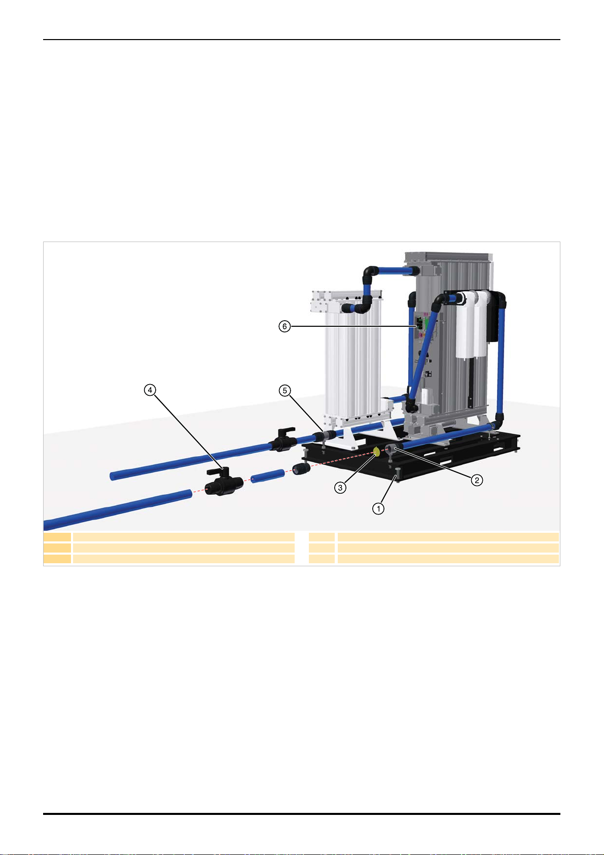
3.3 Mechanical Installation
3.3.1 General Requirements
Ensure that each filter condensate drain is suitably piped away and any effluent is disposed of in accordance with local regulations.
It is important to ensure that all piping materials are suitable for the application, clean and debris free. The diameter of the pipes must be sufficient
to allow unrestricted inlet air supply to the equipment and outlet air supply to the application.
When routing the pipes ensure that they are adequately supported to prevent damage and leaks in the system.
All components used within the system must be rated to at least the maximum operating pressure of the equipment. It is recommended that the
system be protected with suitably rated pressure relief valves.
1 M20 Mounting bolt 4 Isolation valve
2 Compressed air inlet port 5 Outlet port
3 Protective dust cover 6 Electrical control box
3.3.2 Securing the Module
Mounting holes are provided on each corner of the skid. Once the module has been positioned in its final location ensure that it is securely fixed
in place using M20 fixing bolts.
3.3.3 Piping Connections
Remove the protective dust covers from the inlet and outlet ports and connect the system piping. Isolation valves should be fitted to both ports to
allow the module to be isolated during maintenance.
10
Page 15

3.4 Electrical Installation
A fully qualified electrical engineer must undertake all field wiring and electrical work in accordance with local regulations.
3.4.1 BAM Electrical Supply
The module should be connected to a single phase electrical supply through
a switch or circuit breaker.
This device should be:
• Suitable for the application and selected in accordance with local and
national code regulations.
• Clearly and indelibly marked as the disconnecting device for the
equipment.
• Located in close proximity to the equipment and be easily accessible
to the operator.
Note. The disconnection device must be locked in the ‘OFF’ position
during installation.
Overcurrent protection must be fitted as part of the building installation. This
protection should be selected in accordance with local and national code
regulations.
Feed the supply cable through the spare cable gland and connect it to the
electrical supply terminal block. Each wire should be terminated using
suitable ferrules. Secure the cable gland to protect the terminations.
3.4.2 BAM Remote alarm indication
The module is fitted with a set of volt free relay contacts (1A max @ 250Vac
/ 30Vdc) designed for remote alarm indication.
Connection should be made to the Remote alarm terminal block.
O/N Normally open contacts
Comm Common terminal
N/C Normally closed contact
The cable used should be 0.75mm
that it is routed away from high voltage cables.
Note. The relay is energised when the module is operating under normal
conditions.
2
and not exceed 30m in length. Ensure
If the remote alarm indication relay is used, the electrical enclosure will contain more than one live circuit. The relay
connections will remain live when the mains supply is disconnected.
1 Electrical supply terminal block:
2 Remote alarm terminal block
11
Page 16

3.4.3 CO Monitor Remote Alarm
1 Socket
2 Solder pin
3 Main body
4 Locking cap
5 Cable gland
6 Gland nut
Pin configuration viewed
from the front of the socket.
The carbon monoxide analyser is fitted with a set of volt free relay contacts (1A max @ 24Vac / dc) designed for remote alarm indication. The
relay is energised in the non-alarm state (fail-safe) and releases in any alarm condition or in the event of a power failure. The relay can be set to
respond to a given set-point or level of measured carbon monoxide, please refer to the BACO200 user guide for details.
Connection to the monitor is made using the multi-pole connector supplied.
Wiring the connector
1 The connector supplied with the generator will accept 5 - 7mm cable.
2 Strip 17mm of insulation from the cable, and strip 2mm from each wire.
3 Disassemble the plug provided into its component parts.
4 Thread the cable through the component parts of the plug (items 3 - 6) as illustrated below.
5 Solder the pins onto the wires and insert the pins into the socket.
6 Push the socket into the main body until the tabs snap into place.
7 Push the cable gland and nut into the main body and tighten.
8 Attach the connector to the CO Monitor and tighten the locking cap.
12
Page 17

4 Operating the Dryer
-39
err
ser
ECO
ppm CO
MODE
Ref. Description
1 Mode Selection
2 UP Key
3 Down Key
4 Enter / Return Key
5 LCD
Current Measured CO value (ppm)
Gas Alarm
4.1 Overview of controls
4.1.1 Dryer Controls
Ref. Description
1 Power “ON” indicator
2 Service interval indicator
3 Temperature Units
4 LCD
4.1.2 CO Analyser Controls
1.1
-40
Software version
Sizing dewpoint
Actual dewpoint
Dewpoint sensor fault
Service required
Economy mode
13
Page 18

4.2 Starting the equipment
1 Ensure that the inlet and outlet isolation valves are closed.
2 Connect the electrical supply to the module and verify that the power on indicator on the front of the dryer is illuminated.
3 Slowly open the inlet isolation valve and verify that there are no leaks within the module.
4 Check that the system pressure relief valve is closed.
5 Test the condensate drains of the filters and ensure they are discharging correctly into a suitable collection vessel.
6 Slowly open the outlet isolation valve to allow the system to pressurise.
The module is designed for continuous use and, once running, requires no further operator intervention.
4.3 Stopping and depressurising the equipment
1 Close the outlet isolation valve followed by the inlet isolation valve.
2 De-pressurise the module by venting through the drain ball valve on the outlet dust filter.
Note: The drain valve should be opened gradually.
3 Disconnect the electrical supply to the dryer
Note: A small amount of air may be trapped between the inlet isolation valve and the dryer inlet.
14
Page 19

5 Service intervals
Description of Service Required Recommended Interval:
Component Operation
MX Dryer Check POWER ON indicator is illuminated.
MX Dryer Check STATUS / FAULT indicators located on the controller.
System Check for air leaks.
MX Dryer Check the pressure gauges during purging for excessive back pressure.
MX Dryer Check the condition of electrical supply cables and conduits.
MX Dryer Check for cyclic operation.
MX Dryer
Filtration
CO Safe
MX Dryer
- Replace the active exhaust silencers
Recommended Service
Replace the inlet, outlet and control air filters, and service drains.
Recommended Service
Replace the activated carbon cartridges
Recommended Service
Replace / Calibrate dewpoint transmitter (DDS Units only).
Recommended Service
(1)
CO Monitor Calibrate the CO Monitor
CO Monitor
CO Safe
Replace the electrochemical sensor
Recommended Service
Replace the Catalyst cartridges
(2)
Day
Every
Week
Every
Every
Every
Every
Every
Every
Every
month
3 months
6 months
12 months
18 months
24 months
Every
36 months
MX Dryer
MX Dryer
(1) Unlike oil aerosol removal filters which are changed annually to guarantee compressed air quality, the lifetime of the activated carbon cartridges can be attributed to various factors
and require more frequent changes. Factors affecting the lifetime of the cartridges are:
Oil vapour concentration - The higher the inlet concentration of oil vapour, the faster the activated carbon capacity will expire.
Bulk oil - Adsorption filters are designed to remove oil vapour and odours, not liquid oil or aerosols. Poorly maintained or non-existent pre-filtration will cause the OVR filter capacity to
quickly expire.
Temperature - Oil vapour content increases proportionally to inlet temperature, reducing element life. Additionally, as temperature increases, the adsorption capacity decreases, again
reducing element life.
Relative Humidity or Dewpoint - Wet air reduces the adsorptive capacity of the carbon.
Compressor oil changes - When compressor oil is changed, the new lubricant burns off “light ends” which increases the oil vapour content for hours or even weeks
afterwards. This increase in oil vapour content is adsorbed by the OVR filter, significantly reducing its adsorptive life.
The cartridge performance is based upon a maximum oil vapour inlet concentration of 0.018mg/m
These cartridges should be replaced upon detection of vapour, odour or taste.
(2) Under normal operating conditions the catalyst cartridges should be replaced every 24 months. If an oil vapour incident occurs then we recommend that the carbon and catalyst
cartridges are replaced at the same time .
Replace the valve seats and seals.
Recommended Service
Replace the Desiccant.
Recommended Service
3
, with compressed air at 21oC and a pressure dewpoint of -40oC PDP.
Key:
Check
Process Replace
15
Page 20

5.1 Preventative Maintenance Kits
Note. The number of kits required is dependent upon the model of dryer as illustrated below.
Description Catalogue Number Contents Order Qty
Kit: Silencer Element 608620090 Silencer element --
Description BAM10 BAM20 BAM30 BAM40 BAM50 BAM70
Kit: Silencer Element 1 1 1 2 2 3
Description Catalogue No. Contents Order Qty
045AO (BAM10 - 40) 045AO AO Element 1
045AA (BAM10 - 40) 045AA AA Element 1
045AO (BAM10 - 40) 045AO AO Element 1
050AO (BAM50) 050AO AO Element 1
050AA (BAM50) 050AA AA Element 1
050AO (BAM50) 050AO AO Element 1
055AO (BAM70) 055AO AO Element 1
055AA (BAM70) 055AA AA Element 1
055AO (BAM70) 055AO AO Element 1
Note. One kit required for each dryer bank with dewpoint transmitter.
Description Catalogue Number Contents Order Qty
Kit: Service Exchange Hygrometer 608204125
Hygrometer transmitter
1
Fixed orifice
o-ring
Description Catalogue Number Contents Order Qty
Kit: AC Cartridge (BAM10 / BAM20) CAT010ACK
AC Cartridge (x2)
1
O-rings
Kit: AC Cartridge (BAM30 / BAM40) CAT020ACK
AC Cartridge (x4)
1
O-rings
Kit: AC Cartridge (BAM50) CAT030ACK
AC Cartridge (x6)
1
O-rings
Kit: AC Cartridge (BAM70) CAT040ACK
AC Cartridge (x8)
1
O-rings
Description Catalogue Number Contents Order Qty
Kit: BAC Monitor Sensor BACOCOANALYSER Sensor 1
Recommended every 12 months
Recommended every 18 months
16
Page 21

Recommended every 24 month
Description Catalogue Number Contents Order Qty
Kit: Catalyst Cartridge (BAM10 / BAM20) CAT010CK
Catalyst Cartridge (x2)
1
O-rings
Kit: Catalyst Cartridge (BAM30 / BAM40) CAT020CK
Catalyst Cartridge (x4)
1
O-rings
Kit: Catalyst Cartridge (BAM50) CAT030CK
Catalyst Cartridge (x6)
1
O-rings
Kit: Catalyst Cartridge (BAM70) CAT040CK
Catalyst Cartridge (x8)
1
O-rings
Description Catalogue Number Contents Order Qty
Kit: Inlet Valve 608620093
Cylinder valves
1Associated o-rings
Fixing screws
Inlet Valve Kit
Description Catalogue Number Contents Order Qty
Kit: Outlet Valve 608620094
Valve spring assemblies
1Associated o-rings
Fixing nuts and bolts
Outlet Valve Kit
Description Catalogue Number Contents Order Qty
Kit: Exhaust Valve 608620095
Cylinder valve
1
Elbow fittings
Associated o-rings
Fixing screws
Exhaust Valve Kit
Description Catalogue Number Contents Order Qty
Kit: Control Valve 608620096
3-Bank solenoid valve
1
010AA filter element
E009AA filter element
Fixing screws
Control Valve Kit
Recommended every 36 months
Description Catalogue Number Contents Order Qty
Inlet Valve Kit (Catalogue No.608620093)
Kit: Valve Overhaul Kit 608620091
Note. One overhaul kit is required for each dryer bank.
Outlet Valve Kit (Catalogue No.608620094)
Exhaust Valve Kit (Catalogue No.608620095)
Control Valve Kit MXA/MXS (Catalogue No.608620096)
17
Page 22

Note. The quantity of desiccant material required is dependent upon the size of the module.
Ensure that the dryer is filled using a Snowstorm filler and replace the column seals.
Description Catalogue Number Contents Order Qty
Kit: Desiccant AA 608203661 11 Litre Container of AA
--
Kit: Desiccant MS 608203662 11 Litre Container of MS
Description BAM10 BAM20 BAM30 BAM40 BAM50 BAM70
Kit: Desiccant AA (11.2 Ltr) 8 12 14 19 24 33
Kit: Desiccant MS (11.2 Ltr) 1 2 2 3 3 4
Note. One kit is required for each dryer.
Description Catalogue Number Contents Order Qty
Kit: Column Seals 608620098
Column o-rings
1
Outlet plate o-ring
Description Catalogue Number Contents Order Qty
Snowstorm Filler 608201051
Jumbo Snowstorm Filler 1
Column Seal Kits
Snowstorm Filler
18
Page 23

ELEMENTS
Parker filters are designed to produce clean compressed air, gas
and liquid to the highest industry standards. To maintain
impeccable results, Elements within the filter must be replaced
annually.
Choosing the Parker brand means you can be assured that
Elements are readily available, affordable and the most energy
efficient product of its kind on the market. The elements are also
supplied in 100% recyclable packaging. An additional advantage of
purchasing Parker Elements is that you will reduce your company’s
carbon footprint by 190kg. This is the equivalent of a 700 mile flight
from Edinburgh to Berlin!
Parker Filter Elements also prove to be highly efficient when used
in any leading competitor’s filters.
SPECIALISED
SERVICES
Parker Specialist Service Engineers test on-site efficiency
measuring many variables including airflow, pressure,
temperature, dewpoint and power consumption.
Our team of highly trained experts are the best in the industry.
They take into account a range of environmental factors that could
affect your system’s performance. The results from this Specialist
Service are extremely accurate and produce invaluable
information.
Importantly, Parker informed recommendations lead to significant
savings for our customers, which mean they return time and time
again for our advice and products.
SUPPORT
SERVICES
PARTS
Parker Kits make everyday maintenance easy. They are available
for all of our products and are simply value-for money. The Parts
within the kits support our customers’ varied maintenance, repair
and overhaul activities.
Additionally, Preventative Maintenance Kits can be purchased for
dryers and gas generators. These kits mean our customers dryer’s
and generator’s can be serviced easily to ensure optimum
performance.
An extensive range of durable Parker Parts can be obtained within
24 hours to any European, Middle East or African destination.
M.R.O
Maintenance Repair & Overhaul - Parker Technicians are the
industry’s finest. Their skills and qualifications are annually
approved to keep their product and legislation knowledge fresh
and expertise relevant.
With this in mind, Parker offers onsite and on demand servicing to
meet customers’ unique requirements in a timely and efficient
manner.
Parker MRO service ranges from a basic maintenance check
covered under product warranty right through to a comprehensive
programme, which even puts the onsite application under the
microscope.
With customers at the heart of everything Parker does, the MRO
service is no exception to this.
Parker Filter Elements also prove to be highly efficient when used
in any leading competitor’s filters.
Parker Support Services are the first port of call for customers in
need of help or guidance.
The fact that this team is responsible for the production of User
Guides and Manuals gives you an insight into the level and detail
of their parts and product knowledge.
Over-the-phone support is just one way in which Parker’s
extremely knowledgeable team, quickly reduces downtime or
resolves product queries.
On some occasions engineers need to be on site to carry out a
repair. In these cases, the local engineer will be quickly dispatched
to ensure our customers can return to production as soon as
possible.
One-to-one training can also be provided by our Support Services
team. This has enabled hundreds of Parker distributors to gain an
in-depth understanding. Training will also ensure distributors can
make timely repairs and easily maintain their customers’ products.
19
Page 24

6 Troubleshooting
In the unlikely event that a problem occurs on the equipment, this troubleshooting guide can be used to identify the probable cause and remedy.
Troubleshooting should only be attempted by competent personnel. All major repair, and calibration work should be undertaken by a Parker
domnick hunter trained, qualified and approved engineer.
Fault Probable Cause Remedy
Check actual inlet parameters and environmental conditions
against the values quoted at the time of sizing.
Check the condensate drain(s) for faults.
Check the drain hoses are free from kinks and obstructions.
Ensure that the drain isolation valves are fully open.
Check and replace.
Check actual inlet conditions against the values quoted at
the time of sizing.
Check the system for leaks.
Ensure that the drain cocks and pressure relief valves are
closed.
Check that the dryer “POWER ON” indicator is illuminated. If
it is not check the isolator and fuses.
Check that the compressor “POWER ON” indicator is
illuminated. If it is not check the isolator and fuses.
Poor dewpoint identified by water in the
downstream piping and equipment
High pressure drop resulting in low pressure
gauge readings or intermittent operation of the
downstream equipment.
Interruption of the air supply downstream
leading to a rapid loss of system pressure.
Dryer is operating outside of its sizing criteria
Bypass valve is open. Check bypass valve is fully closed.
Dryer has recently been started. Allow time for the system to “dry down”
The condensate is not being drained.
Regeneration column pressure > 350mbar. Replace the exhaust silencers.
Timer malfunction. Contact a PdhFNS approved service agent.
Valve malfunction. Contact a PdhFNS approved service agent.
Desiccant is approaching the end of its useful life. Contact a PdhFNS approved service agent.
The pre / after filtration is approaching the end of its
operational life.
The dryer is being overflowed or is operating at a
reduced system pressure.
An isolation valve is partially closed. Check the position of all the isolation valves.
Pressure loss from the system.
The dryer tripped due to power supply interruption to
the dryer.
The compressor tripped due to power supply
interruption to the compressor.
Isolation valve closed Check the position of the isolation valves.
Compressor switched off. Check the compressor.
Fault shutdown event. Check the dryer fault indicators.
20
Page 25

R
Declaration of Conformity
EN
BAM10, BAM20, BAM30, BAM40, BAM50, BAM70
Directives
2014/68/EU
2014/30/EU
2014/35/EU
2011/65/EU
Standards used
EN60204-1: 2006 + A1:2009
EN 61000
-6-2 : 2005
EN 61000
-6-3 : 2007 + A1:2011
EN 61000
-3-2 : 2006 + A2:2009
EN 61000
-3-3 : 2008
Generally in accordance with ASMEVIII Div 1 : 2004.
PED Assessment Route :
B + D
EC Type-examination Certificate:
COV0912556/1
Notified body for PED:
Lloyds Register Verification
71 Fenchurch St. London
EC3M 4BS
Authorised Representative
Damian Cook
Division Engineering Manager
Parker Hannifin Manufacturing Limited
I declare that as the authorised representative, the above information in relation to the supply / manufacture of this product, is
in conformity with the standards and other related documents following the provisions of the above Directives.
Signature:
Date: 24/11/2016
Declaration Number: 00273/241116
Dukesway, TVTE, Gateshead, Tyne & Wear, NE11 0PZ. UK
Parker Hannifin Manufacturing Limited
Breathing Air Purifier
Declaration
Page 26

INHALTSVERZEICHNIS
1 Sicherheitshinweise ...................................................................................................................................................................................25
1.1 Kennzeichen und Symbole................................................................................................................................................................ 26
2 Beschreibung.............................................................................................................................................................................................. 27
2.1 Technische Spezifikationen ..............................................................................................................................................................27
2.2 Zulassungen, Konformität und Freistellungen ................................................................................................................................28
2.3 Konstruktionsmaterialien ..................................................................................................................................................................29
2.4 Gewichte und Abmessungen ............................................................................................................................................................30
2.4.1 Modul..........................................................................................................................................................................................30
2.4.2 Modul mit Verpackung................................................................................................................................................................30
2.5 Annahme und Prüfung des Geräts ...................................................................................................................................................31
2.5.1 Lagerung ....................................................................................................................................................................................31
2.5.2 Auspacken..................................................................................................................................................................................31
2.5.3 Anheben und Handhabung ........................................................................................................................................................ 31
2.6 Übersicht über das Gerät...................................................................................................................................................................32
3 Installation und Inbetriebnahme................................................................................................................................................................ 33
3.1 Empfohlener Systemaufbau ..............................................................................................................................................................33
3.2 Aufstellort des Geräts ........................................................................................................................................................................33
3.2.1 Umgebung.................................................................................................................................................................................. 33
3.2.2 Platzbedarf .................................................................................................................................................................................33
3.3 Mechanische Installation ...................................................................................................................................................................34
3.3.1 Allgemeine Anforderungen......................................................................................................................................................... 34
3.3.2 Befestigung des Moduls .............................................................................................................................................................34
3.3.3 Leitungsanschlüsse....................................................................................................................................................................34
3.4 Elektrische Installation ......................................................................................................................................................................35
3.4.1 BAM-Stromversorgung............................................................................................................................................................... 35
3.4.2 BAM-Fernüberwachung von Alarmen ........................................................................................................................................35
3.4.3 CO-Monitor zur Fernanzeige von Alarmen.................................................................................................................................36
4 Bedienung des Trockners..........................................................................................................................................................................37
4.1 Übersicht über die Bedienelemente .................................................................................................................................................37
4.1.1 Bedienelemente des Trockners..................................................................................................................................................37
4.1.2 Bedienelemente des CO-Analysators ........................................................................................................................................37
4.2 Starten des Geräts..............................................................................................................................................................................37
4.3 Stoppen des Geräts und Ablassen des Drucks...............................................................................................................................38
5 Wartungsintervalle...................................................................................................................................................................................... 39
5.1 Sätze für die vorbeugende Wartung .................................................................................................................................................40
6 Fehlerbehebung..........................................................................................................................................................................................44
7 Konformitätserklärung ...............................................................................................................................................................................45
Page 27

Page 28

1 Sicherheitshinweise
Vor der Inbetriebnahme des Geräts müssen die Sicherheitshinweise und Anweisungen in diesem Handbuch vom zuständigen Personal
gründlich gelesen und verstanden worden sein.
BENUTZERHAFTUNG
MÄNGEL AN ODER FALSCHE AUSWAHL BZW. VERWENDUNG DER HIER BESCHRIEBENEN PRODUKTE ODER ZUGEHÖRIGEN
ELEMENTE KÖNNEN ZUM TOD FÜHREN ODER VERLETZUNGEN BZW. SACHSCHÄDEN ZUR FOLGE HABEN.
Dieses Dokument und andere Mitteilungen der Parker Hannifin Corporation, der Tochtergesellschaften und Vertragshändler stellen Produkt- oder
Systemvarianten zur weiteren Auswertung durch Anwender mit technischem Know-how dar.
Der Anwender ist auf der Grundlage seiner eigenen Analyse und Testergebnisse allein für die endgültige Auswahl des Systems und der
Komponenten verantwortlich. Er hat sicherzustellen, dass alle Leistungs-, Haltbarkeits-, Wartungs-, Sicherheits- und Warnvoraussetzungen des
jeweiligen Einsatzbereichs erfüllt sind. Der Anwender ist dazu verpflichtet, alle Aspekte der Anwendung zu analysieren, geltende
Branchennormen einzuhalten und die Produktinformationen im aktuellen Produktkatalog sowie in anderen von Parker bzw. den
Tochtergesellschaften oder Vertragshändlern zur Verfügung gestellten Materialien zu beachten.
Soweit Parker, die Tochtergesellschaften oder Vertragshändler Komponenten oder Systemvarianten basierend auf technischen Daten oder
Spezifikationen liefern, die vom Anwender bereitgestellt wurden, ist der Anwender dafür verantwortlich, festzustellen, dass diese technischen
Daten und Spezifikationen für alle Anwendungen und vernünftigerweise vorhersehbaren Verwendungszwecke der Komponenten oder Systeme
geeignet und ausreichend sind.
Installation, Inbetriebnahme, Wartung und Reparatur dürfen nur von entsprechend ausgebildetem und von Parker Hannifin zugelassenem
Personal durchgeführt werden.
Wenn das Gerät nicht gemäß der in diesem Benutzerhandbuch spezifizierten Anweisungen verwendet wird, kann es zu einem unbeabsichtigten
Druckabbau und infolgedessen zu schweren Verletzungen oder Sachschäden kommen.
Beim Umgang, bei der Installation und der Bedienung des Geräts muss das Personal sichere technische Verfahren einsetzen und alle
entsprechenden Bestimmungen, Gesundheits- und Sicherheitsvorschriften befolgen sowie alle gesetzlichen Sicherheitsbestimmungen einhalten.
Vergewissern Sie sich vor der Durchführung jeglicher in diesem Handbuch beschriebener Wartungsarbeiten, dass das Gerät drucklos und von
der Stromversorgung getrennt ist.
Parker Hannifin kann nicht jeden Umstand vorhersehen, der eine potenzielle Gefahrenquelle darstellt. Die Warnungen in diesem Handbuch
decken die bekanntesten Gefahrenquellen ab, können jedoch niemals allumfassend sein. Setzt der Anwender ein Bedienverfahren, ein
Geräteteil oder eine Arbeitsmethode ein, die nicht ausdrücklich von Parker Hannifin empfohlen wurden, muss der Anwender sicherstellen, dass
das Gerät nicht beschädigt wird bzw. keine Personen- oder Sachschäden verursachen kann.
Die meisten Unfälle, die während des Betriebs und der Wartung von Maschinen passieren, lassen sich darauf zurückführen, dass grundlegende
Sicherheitsvorschriften und -verfahren missachtet wurden. Unfälle können durch das Bewusstsein vermieden werden, dass jede Maschine eine
potenzielle Gefahr darstellt.
Sollten Sie eine verlängerte Garantiezeit wünschen oder einen an Ihre Bedürfnisse angepassten Wartungsvertrag bzw. Schulungen für dieses
oder ein anderes Gerät aus der Produktpalette von Parker Hannifin benötigen, wenden Sie sich bitte an die nächstgelegene Vertretung von
Parker Hannifin.
Informationen zur nächstgelegenen Vertriebsniederlassung von Parker Hannifin finden Sie unter www.parker.com/dhfns.
Bewahren Sie dieses Handbuch zur späteren Verwendung auf.
25
Page 29

1.1 Kennzeichen und Symbole
Folgende Kennzeichen und internationale Symbole dienen als Hinweise auf dem Gerät und in diesem Handbuch:
Vorsicht, Anwenderhandbuch lesen. Gehörschutz tragen.
Gefahr durch Stromschlag Komponenten im System unter Druck
Weist auf Handlungen oder Verfahren hin, die bei
fehlerhafter Durchführung zu Verletzungen und zum Tod
führen können.
Weist auf Handlungen oder Verfahren hin, die bei
fehlerhafter Durchführung zu Schäden am Gerät führen
können.
Weist auf Handlungen oder Verfahren hin, die bei
fehlerhafter Durchführung zu einem Stromschlag führen
können.
Anwenderhandbuch lesen.
Setzen Sie zum Transport des Trockners einen
Gabelstapler ein.
Fernsteuerung ? Trockner kann automatisch und ohne
Vorwarnung starten.
Conformité Européenne
Die Entsorgung gebrauchter Teile muss immer gemäß
den örtlichen Entsorgungsbestimmungen erfolgen.
Elektro- und Elektronik-Altgeräte sollten nicht mit dem
Hausmüll entsorgt werden.
26
Page 30

2 Beschreibung
2.1 Technische Spezifikationen
Durchflussdaten
Modell Leitungsgröße
BAM10
BAM20
BAM30
BAM40
BAM50
BAM70
Die angegebenen Durchflussraten beziehen sich auf den Betrieb bei 7 bar ü, 20 °C, 1 bar a und einem relativen Wasserdampfdruck von 0 %.
G 2" 113 6,8 408 240 90,4 5,4 326,4 192
G 2" 170 10,2 612 360 136 8,2 489,6 288
G 2" 213 12,8 765 450 170,4 10,2 612 360
G 2" 283 17,0 1.020 600 226,4 13,6 816 480
G 2 1/2" 354 21 1.275 750 283,2 16,8 1.020 600
G 2 1/2" 496 30 1.785 1.050 396,8 24 1.428 840
l/s
Einlass Auslass
m3/min m3/h
cfm l/s
m3/min m3/h
Leistung
Drucktaupunkt
Trocknermodell
o
Alle Modelle
Die ISO 8573-1-Klassifizierungen gelten, wenn der Trockner mit der gelieferten Filtervorrichtung installiert wurde.
-40 -40 Klasse 2
(Standard)
C
Verunreinigungen Einheiten
Öl/Schmiermittel
mg/m
3
Wasser ppm 7.913 24 67
Kohlenmonoxid (CO) ppm 39 < 0,01 5
Kohlendioxid (CO2)
Sauerstoff (O2)
Vol. -% 20,9 20,9 20,4 ? 21,4
Stickoxide (NO + NO2)
Schwefeldioxid (SO2)
Referenzbedingungen: 20
o
C, 1 bar (a), trocken. Druckluftbedingungen: 7 bar Überdruck, 35 oC
Wasserklassifikation nach
ISO 8573-1:2010
o
F
Einlasskonzentratio
(Alle Modelle)
Ref.
(Standard)
n
Auslasskonzentration
(Alle Modelle)
Europäisches
Arzneibuch
11, 3 0,011 0,1
ppm 744 109 500
ppm 13 1,8 2
ppm 7 < 0,01 1
Betriebsdaten
cfm
Min.
o
Modell
Alle Modelle
Min. Betriebsdruck Max. Betriebsdruck
bar ü psi g bar ü psi g
Betriebstemperatur
o
C
4 58 13 188,5 5 41 35 95
Elektrische Daten
BAM10 BAM20 BAM30 BAM40 BAM50 BAM70
Versorgungsspannung
Anschlusstyp
Leistungsaufnahme
Sicherung
1 Druckstoßsicherung (T), 250 VAC, 5 x 20 mm, Hochleistungssicherung, Schaltleistung 1.500 A bei 250 V, IEC 60127-2
1
90 – 264V, einphasig, 50/60 Hz
Festverdrahtet
21 W (max.)
T 3,15 A
Betriebstemperatur
F
Max.
o
C
o
F
27
Page 31

Korrekturfaktoren
Temperaturkorrekturfaktor (Temperature Correction Factor, CFT)
o
Maximale
Einlasstemperatur
Druckkorrekturfaktor (Pressure Correction Factor, CFP)
Maximaler
Eingangsdruck
C
o
F
CFT
bar ü
psi g
CFP
1,60 1,33 1,14 1,00 0,89 0,80 0,73 0,67 0,62 0,57
25 30 35
77 86 95
1,00 1,00 1,00
4 5 6 7 8 9 10 11 12 13
58 73 87 100 116 131 145 160 174 189
Taupunkt-Korrekturfaktor (Dewpoint
Correction Factor, CFD)
Maximaler
Eingangsdruck
DTP oC
DTP oF
CFD
Standard
-40
-40
1,00
Umgebungsdaten
Relative Luftfeuchtigkeit
IP-Schutzart
Verschmutzungsgrad
Maximale Höhe
Geräuschpegel
1 Verschmutzungsgrad 2 gibt an, dass für den sicheren Betrieb dieser Ausrüstung in der Umgebung nur nicht leitende Verschmutzungen (z. B. Feststoffe, Flüssigkeiten und Gase)
oder vorübergehende Kondensation vorhanden sein dürfen.
1
55 %
IP55, nur für den Einsatz in geschlossenen Räumen
2
2.000 m
(6.562 ft)
< 80 dB(A)
2.2 Zulassungen, Konformität und Freistellungen
ZULASSUNGEN, AKKREDITIERUNGEN UND VERBÄNDE
INTERNATIONALE ZULASSUNGEN
Konformität
Die Leistung der Druckluft-Atemluftaufbereitungseinheiten der BAM-Produktreihe in Bezug auf die
Reduzierung schädlicher, in Druckluft auftretender Verunreinigungen wurde gemäß den
Anforderungen des Europäischen Arzneibuchs unabhängig überprüft.
Unabhängige Bestätigung der Leistung
Die in den BAM-Atemluftaufbereitungseinheiten verwendeten OIL-X EVOLUTIONKoaleszenzfilter wurden gemäß ISO 12500-1 und ISO 8573-4 geprüft.
Die OIL-X EVOLUTION-Trockenpartikelfilter wurden gemäß ISO 8573-4 geprüft.
Die von den Einheiten der BAM-Produktreihe produzierte Luftqualität wurde durch eine
unabhängige behördliche Prüfstelle zertifiziert. Die von den BAM-Atemluftaufbereitungseinheiten
bereitgestellte Luftqualität übertrifft die Anforderungen des Europäischen Arzneibuchs bei Weitem
(Arzneimittelbuch 2011, 7. Auflage).
Jegliche Leistungsvalidierungen werden von dem unabhängigen Unternehmen Lloyd's Register
und/oder dem IUTA (Institut für Energie- und Umwelttechnik e.V.) verifiziert.
28
Page 32

2.3 Konstruktionsmaterialien
Rahmensockel
Filterstützrahmen
Ein-/Auslassanschlüsse
Schalldämpfer-Leitblech und Endkappe
Säulen, Grundplatten und Ventilblöcke
Grund- und Spülendplatten
Endplatten von Einlass-, Auslass- und Abluftventilblock
Einlass- und Abluftzylinder
Trocknerfüße
Montageplatte hinten
Koaleszenzfilter
Hygrometergehäuse
Fittinge
Druckmessgerät
Adsorbat
Dichtungsmaterialien
Beschichtung
150 x 75 x 18 mm BS4-Parallelflanschkanal
Unlegierte 5-mm-Stahlplatte
50 x 50 x 6 mm gleiche Winkel (BS4 und BS EN 10056)
Stahl 316
Aluminium
Aluminiumextrusion EN AW-6063 T6
Guss bearbeitet EN AW-6082 T6
Guss bearbeitet EN AC-44100-F
Aluminiumlegierung
8-mm-Stahlplatte
14 SWG unlegierter Stahl
Aluminiumgehäuse
GR316 – BS970
Vernickeltes Messing und vernickelter unlegierter Stahl
Gehäuse und Anzeige: ABS-Kunststoff; Kupplung und Antriebsmechanismus: Messing
Aktivierte Tonerde und 13x MS
Nitril, Viton, EPDM, PTFE (Band)
Epoxidbeschichtung
29
Page 33

2.4 Gewichte und Abmessungen
H
W
D
2.4.1 Modul
H
(a)
(b)
Modell
BAM10
BAM20
BAM30
BAM40
BAM50
BAM70
H B T (a) (b) (c) (d)
mm Zoll mm Zoll mm Zoll mm Zoll mm Zoll mm Zoll mm Zoll kg lb
1.797 70,7 1.260 49,6 1.655 65,2 270 10,6 280 11, 0 850 33,5 880 34,6 600 1322,8
1.797 70,7 1.260 49,6 1.655 65,2 270 10,6 280 11, 0 850 33,5 880 34,6 700 1543,2
2.042 80,4 1.260 49,6 1.655 65,2 270 10,6 280 11, 0 850 33,5 880 34,6 800 1763,7
2.042 80,4 1.260 49,6 1.655 65,2 270 10,6 280 11, 0 850 33,5 880 34,6 900 1984,2
2.042 80,4 1.260 49,6 1.950 76,8 270 10,6 280 11, 0 850 33,5 880 34,6 110 0 2425,1
2.042 80,4 1.260 49,6 1.950 76,8 270 10,6 280 11, 0 850 33,5 880 34,6 1400 3086,5
2.4.2 Modul mit Verpackung
Modell
BAM10
BAM20
BAM30
BAM40
BAM50
BAM70
H B T
mm Zoll mm Zoll mm Zoll kg lb
2039 80,3 1418 55,8 1853 73 853 1880,5
2039 80,3 1418 55,8 1853 73 953 2101,0
2284 89,9 1418 55,8 1853 73 1067 2352,3
2284 89,9 1418 55,8 1853 73 1167 2572,8
2284 89,9 1418 55,8 2148 84,6 1388 3060,0
2284 89,9 1418 55,8 2148 84,6 1688 3721,4
(c)
(d)
W D
Modulabmessungen
Abmessungen
Gewicht
Gewicht
30
Page 34

2.5 Annahme und Prüfung des Geräts
W D
H
Modell
Schwerpunkt
H B T
mm Zoll mm Zoll mm Zoll
BAM10
691 27,2 599 23,6 655 25,8
BAM20
745 29,3 622 24,5 663 26,1
BAM30
828 32,6 598 23,5 702 27,6
BAM40
859 33,8 619 24,4 722 28,4
BAM50
878 34,6 615 24,2 860 33,9
BAM70
925 36,4 661 26,0 931 36,7
Das Gerät wird in einem stabilen Lattenverschlag geliefert, der dafür vorgesehen ist, mit einem Gabelstapler oder einem Gabelhubwagen bewegt
zu werden. Überprüfen Sie bei der Lieferung des Geräts den Lattenverschlag und den Inhalt auf Schäden und stellen Sie sicher, dass die
nachfolgend aufgeführten Teile im Lieferumfang des Trockners enthalten sind: Bei Schäden am Lattenverschlag informieren Sie umgehend das
Versandunternehmen und benachrichtigen Sie Ihre lokale Niederlassung von Parker domnick hunter.
2.5.1 Lagerung
Lagern Sie das Gerät in der Versandkiste in einer sauberen, trockenen Umgebung. Wird die Kiste an einem Ort gelagert, an dem die
tatsächlichen nicht den in den technischen Daten vorgegebenen Umgebungsbedingungen entsprechen, muss das Gerät unbedingt vor dem
Auspacken zu seinem endgültigen Einsatz-/Installationsort gebracht werden. Dort muss es sich zunächst stabilisieren. Die Nichtbeachtung
dieses Hinweises könnte zu Feuchtigkeitsbildung und einer Schädigung des Geräts führen.
2.5.2 Auspacken
Die Holzlatten des Verschlags sind mit Nägeln befestigt. Beginnen Sie an der Oberseite und entfernen Sie vorsichtig jede Holzlatte einzeln.
Bewahren Sie diese Latten sicher zur späteren Verwendung auf.
2.5.3 Anheben und Handhabung
Das Modul ist mit Hebetaschen ausgestattet, um das Anheben des Geräts mit einem Gabelstapler zu erleichtern. Der Schwerpunkt der Module
ist in der Abbildung unten dargestellt.
31
Page 35

2.6 Übersicht über das Gerät
Legende:
Nr. Beschreibung Nr. Beschreibung
1 Druckluft-Einlassanschluss 7 Hocheffizienter Staubfilter
2 Wasserabscheider 8
3 Universalkoaleszenzfilter 9 Anzeige des Trockners
4 Hocheffizienter Koaleszenzfilter 10 Säulendruck-Messgerät
5 PNEUDRI-Drucklufttrockner 11 Elektrischer Steuerkasten
6 Katalysator 12 Auslassanschluss
n. Der Druckregler ist werkseitig auf 2 bar (29 psi) eingestellt und sollte keine Anpassung erfordern.
Kohlenmonoxidanalysator und Druckregler
n
32
Page 36

3 Installation und Inbetriebnahme
Installation, Inbetriebnahme, Wartung und Reparaturen dürfen nur von entsprechend ausgebildetem und von Parker
domnick hunter zugelassenem Personal durchgeführt werden.
3.1 Empfohlener Systemaufbau
Das Modul muss, einem Feuchtluftbehälter nachgeschaltet, mit der mitgelieferten Vorfiltrations- und einer optionalen
Kondensatverwaltungseinrichtung installiert werden, um sowohl die Produktspezifikationen als auch die örtlichen Umgebungsanforderungen zu
erfüllen. Dazu gehören die folgenden Komponenten:
Hinweis: Wenn die vor- und nachgeschalteten Filtrationseinrichtungen nicht gewartet werden, erlischt die Garantie für das Modul.
1 Kompressor 4 Atemluftmodul
2 Feuchtluftbehälter 5 Auslass zum System
3 Absperrventil
3.2 Aufstellort des Geräts
3.2.1 Umgebung
Das Gerät muss im Innenbereich in einer Umgebung aufgestellt werden, in der es vor direktem Sonnenlicht, Feuchtigkeit und Staub geschützt ist.
Änderungen der Temperatur, Feuchtigkeit sowie Luftverschmutzung beeinflussen die Betriebsumgebung des Geräts und können Sicherheit und
ordnungsgemäßen Betrieb beeinträchtigen. Es liegt in der Verantwortung des Kunden, sicherzustellen, dass die angegebenen
Umgebungsbedingungen für das Gerät eingehalten werden.
3.2.2 Platzbedarf
Das Gerät muss auf einer ebenen Stellfläche montiert werden, die das Eigengewicht sowie das Gewicht aller Zubehörteile tragen kann. Die
Mindestmaße der Stellfläche sind unten genauer beschrieben, allerdings muss um das Gerät ausreichend Platz für Luftzirkulation, Zugang bei
Wartungsarbeiten und Ansetzen von Hebezeug vorhanden sein. Es wird ein Mindestabstand von etwa 500 mm an allen Seiten des Moduls und
1.000 mm über dem Trockner empfohlen.
Stellen Sie das Gerät NICHT so auf, dass es nur schlecht bedient oder vom Stromnetz getrennt werden kann.
33
Page 37

3.3 Mechanische Installation
3.3.1 Allgemeine Anforderungen
Es ist sicherzustellen, dass alle Filterkondensatablässe mit geeigneten Auslassrohren versehen sind und alle Abwässer gemäß den örtlichen
Bestimmungen abgeleitet werden.
Außerdem ist sicherzugehen, dass das gesamte Leitungsmaterial für die Anwendung geeignet, sauber und frei von Verschmutzungen ist. Der
Durchmesser der einzelnen Leitungen muss groß genug sein, um eine unbegrenzte Einlassluftversorgung zum Gerät sowie
Auslassluftversorgung zur Anwendung zu ermöglichen.
Beim Verlegen der Rohre ist auf eine entsprechende Abstützung zu achten, um Schäden und Lecks am System zu verhindern.
Alle Komponenten des Systems müssen mindestens auf den maximalen Betriebsdruck des Geräts ausgelegt sein. Es wird empfohlen, das
System mit Überdruckventilen entsprechender Nennkapazität zu schützen.
1 M20-Montageschrauben 4 Absperrventil
2 Druckluft-Einlassanschluss 5 Auslassanschluss
3 Staubschutzabdeckung 6 Elektrischer Steuerkasten
3.3.2 Befestigung des Moduls
In jeder Ecke des Rahmens befinden sich Befestigungslöcher. Sobald sich das Modul an seinem endgültigen Standort befindet, vergewissern Sie
sich, dass es mit M20-Befestigungsschrauben sicher befestigt ist.
3.3.3 Leitungsanschlüsse
Entfernen Sie die Staubschutzabdeckung an den Ein- und Auslassanschlüssen und schließen Sie die Systemleitung an. Beide Anschlüsse
sollten mit Absperrventilen versehen werden, um das Modul für Wartungsarbeiten isolieren zu können.
34
Page 38

3.4 Elektrische Installation
Sämtliche Feldverdrahtungen und elektrischen Arbeiten müssen von einem entsprechend qualifizierten Techniker gemäß
den örtlichen Bestimmungen durchgeführt werden.
3.4.1 BAM-Stromversorgung
Der Anschluss des Moduls an eine einphasige Stromversorgung muss über
einen Schalter oder Schutzschalter erfolgen.
Das Gerät sollte:
• für die Anwendung geeignet und entsprechend den örtlichen und
nationalen Bestimmungen ausgewählt werden,
• eindeutig und dauerhaft als Trenneinrichtung der Einheit
gekennzeichnet sein,
• sich in unmittelbarer Nähe der Anlage befinden sowie für den
Bediener leicht zugänglich sein.
Hinweis: Die Trenneinrichtung muss während der Installation
ausgeschaltet („OFF“-Stellung) sein.
Eine Schutzeinrichtung gegen Überstrom muss als Teil der
Gebäudeinstallation vorhanden sein. Die Auswahl dieser Schutzeinrichtung
sollte gemäß den örtlichen und nationalen Bestimmungen erfolgen.
Führen Sie das Netzkabel durch die freie Kabelverschraubung und
verbinden Sie es mit dem Klemmenblock für die Stromversorgung.
Sämtliche Drähte müssen mit geeigneten Klemmringen terminiert werden.
Sichern Sie die Kabelverschraubung, um die Verbindungen zu schützen.
3.4.2 BAM-Fernüberwachung von Alarmen
Jedes Modul ist mit einem Satz spannungsfreier Relaiskontakte (max. 1 A
bei 250 VAC/30 VDC) für die Fernüberwachung von Alarmen ausgestattet.
Der Anschluss sollte am Klemmenblock für Fernalarme erfolgen.
NO Stromlos geöffnete Kontakte (Schließer)
Comm Gemeinsame Klemme
NC Stromlos geschlossener Kontakt (Öffner)
Die Kabel sollten einen Querschnitt von 0,75 mm
Länge von 30 m besitzen. Stellen Sie sicher, dass sie in angemessenem
Abstand zu Hochspannungskabeln verlegt werden.
Hinweis: Das Relais ist aktiviert, wenn das Modul unter normalen
Bedingungen betrieben wird.
Wenn ein Relais zur Fernanzeige von Alarmen verwendet wird, enthält das Elektrogehäuse mehr als einen
spannungsführenden Stromkreis. Die Relaisanschlüsse führen auch dann Spannung, wenn die Netzversorgung
abgeschaltet ist.
2
und eine maximale
1 Klemmenblock für die Stromversorgung
2 Klemmenblock für Fernalarme
35
Page 39

3.4.3 CO-Monitor zur Fernanzeige von Alarmen
1 Buchse
2 Lötstift
3 Hauptgehäuse
4 Verschlusskappe
5 Kabelstopfbuchse
6 Stopfbuchsenmutter
Die Anschlussbelegung von
der Vorderseite der Buchse
betrachtet
Der Kohlenmonoxidanalysator ist mit einem Satz spannungsfreier Relaiskontakte (max. 1 A bei 24 VAC/VDC) für die Fernüberwachung von
Alarmen ausgestattet. Befindet sich das Gerät nicht im Alarmstatus (ausfallsicher), ist das Relais aktiviert und löst bei Alarmzustand oder bei
einem Ausfall der Stromversorgung aus. Das Relais kann so eingestellt werden, dass es bei einem festgelegten Sollwert oder bei einem
bestimmten Niveau des gemessenen Kohlenmonoxidgehalts reagiert. Weitere Informationen hierzu finden Sie im BACO200-Benutzerhandbuch.
Der Anschluss an den Monitor erfolgt mithilfe des mitgelieferten mehrpoligen Steckverbinders.
Verdrahtung des Steckers
1 Der im Lieferumfang des Generators enthaltene Stecker eignet sich für 5- bis 7-mm-Kabel.
2 Entfernen Sie vom Kabel 17 mm der Isolierung und von jedem Draht 2 mm.
3 Zerlegen Sie den bereitgestellten Stecker in die einzelnen Komponenten.
4 Führen Sie das Kabel durch die Komponenten des Steckers (Teile 3 ? 6), wie unten dargestellt.
5 Löten Sie die Stifte auf den Drähten fest und schieben Sie die Stifte in die Buchse.
6 Drücken Sie die Buchse in das Hauptgehäuse, bis die Lötfahnen einrasten.
7 Schieben Sie die Kabelverschraubung und die Mutter in das Hauptgehäuse und ziehen Sie sie fest.
8 Schließen Sie den Steckverbinder an den CO-Monitor an und ziehen Sie die Verschlusskappe fest.
36
Page 40

4 Bedienung des Trockners
Nr. Beschreibung
1 Netzkontrollanzeige (Power „ON“)
2 Anzeige für das Wartungsintervall
3 Maßeinheiten für die Temperatur
4 LCD-Anzeige
Softwareversion
Auslegungstaupunkt
Tatsächlicher Taupunkt
Taupunkt-Sensorfehler
Wartung erforderlich
Sparmodus
-39
err
ser
ECO
ppm CO
MODE
4.1 Übersicht über die Bedienelemente
4.1.1 Bedienelemente des Trockners
1.1
-40
4.1.2 Bedienelemente des CO-Analysators
Nr. Beschreibung
1 Modusauswahl
2 Tas te „AUF“
3 Tas te „AB“
4 Eingabetaste
5 LCD-Anzeige
Aktuell gemessener CO-Wert (ppm)
Gasalarm
4.2 Starten des Geräts
1 Stellen Sie sicher, dass die Ein- und Auslassabsperrventile geschlossen sind.
2 Schließen Sie das Modul an die Stromversorgung an und prüfen Sie, ob die Netzkontrollanzeige an der Vorderseite des Trockners leuchtet.
3 Öffnen Sie langsam das Einlassabsperrventil und stellen Sie sicher, dass innerhalb des Moduls keine Undichtigkeiten vorhanden sind.
4 Prüfen Sie, ob das Überdruckventil des Systems geschlossen ist.
5 Überprüfen Sie die Kondensatablässe der Filter und vergewissern Sie sich, dass das Kondensat wie vorgeschrieben in einen geeigneten
Auffangbehälter abgeleitet wird.
37
Page 41

6 Öffnen Sie langsam das Auslassabsperrventil, um das System mit Druck zu beaufschlagen.
Das Modul ist für den Dauerbetrieb ausgelegt. Wenn es läuft, sind keine weiteren Bedienvorgänge erforderlich.
4.3 Stoppen des Geräts und Ablassen des Drucks
1 Schließen Sie zunächst das Auslass- und anschließend das Einlassabsperrventil.
2 Lassen Sie über das Ablassventil am Auslassstaubfilter den Druck aus dem Trockner ab.
Hinweis: Das Ablassventil muss langsam geöffnet werden.
3 Trennen Sie den Trockner von der Stromversorgung.
Hinweis: Es ist möglich, dass zwischen dem Einlassabsperrventil und dem Trocknereinlass ein wenig Luft eingeschlossen ist.
38
Page 42

5 Wartungsintervalle
Beschreibung der erforderlichen Wartung Empfohlenes Intervall:
Komponente Vorgehensweise
MX-Trockner Prüfen, ob die Netzkontrollanzeige (POWER ON) leuchtet.
MX-Trockner STATUS-/FEHLER-Anzeige (STATUS/FAULT) am Regler prüfen.
System Auf Luftverlust prüfen.
MX-Trockner Die Druckmessgeräte während des Spülens auf zu hohen Staudruck prüfen.
MX-Trockner Zustand der elektrischen Versorgungskabel und Leitungsführungen prüfen.
MX-Trockner Zyklischen Betrieb prüfen.
MX-Trockner
Filtration
CO-Safe
MX-Trockner
Aktiven Abluftschalldämpfer austauschen.
Empfohlene Wartung
Einlass-, Auslass- und Steuerluftfilter austauschen und Ablässe warten.
Empfohlene Wartung
Die Aktivkohle-Filterelemente austauschen.
Empfohlene Wartung
Taupunkttransmitter ersetzen/kalibrieren (nur DDS-Einheiten).
Empfohlene Wartung
(1)
CO-Monitor CO-Monitor kalibrieren.
CO-Monitor
CO-Safe
Den elektrochemischen Sensor austauschen.
Empfohlene Wartung
Katalysatorfilterelemente austauschen.
(2)
Tag
Jede
Jeden
Woche
Jeden
Monat
Alle
3 Monate
Alle
6 Monate
Alle
12 Monate
Alle
18 Monate
Alle
24 Monate
Alle
36 Monate
MX-Trockner
MX-Trockner
(1) Im Gegensatz zu Filtern für die Abscheidung von Ölaerosolen, die zur Gewährleistung der Druckluftqualität jährlich ausgetauscht werden, kann die Lebensdauer eines AktivkohleFilterelements von einer Vielzahl unterschiedlicher Faktoren abhängen, die einen häufigeren Austausch erfordern. Negative Faktoren für die Lebensdauer der Filterelemente sind:
Ölnebelkonzentration: Je höher die Ölnebel-Einlasskonzentration ist, desto schneller ist die Kapazität der Aktivkohle erschöpft.
Öl: Adsorptionsfilter dienen der Abscheidung von Ölnebel und Gerüchen nicht der Entfernung von flüssigem Öl oder Aerosolen. Schlecht gewartete oder nicht vorhandene Vorfiltration
führt dazu, dass die OVR-Filterkapazität für die Ölnebelabscheidung schnell erschöpft ist.
Temp eratur : Der Ölnebelgehalt steigt proportional zur Einlasstemperatur an und verringert so die Lebensdauer des Filterelements. Darüber hinaus verringert sich mit steigender
Temperatur auch die Adsorptionskapazität, was ebenfalls die Lebensdauer des Filterelements verkürzt.
Relative Luftfeuchtigkeit oder Taupunkt: Feuchte Luft verringert die Adsorptionsfähigkeit der Aktivkohle.
Austausch des Kompressoröls: Bei einem Austausch des Kompressoröls werden durch den neuen Schmierstoff „lose Enden“ abgebrannt, was zu einem Anstieg des Ölnebelgehalts
für Stunden oder sogar Wochen führt. Dieser erhöhte Ölnebelgehalt wird vom OVR-Filter adsorbiert, wodurch sich die Lebensdauer des Filters erheblich reduziert.
Die Filterelementleistung basiert auf einer maximalen Ölnebel-Einlasskonzentration von 0,018 mg/m
Diese Filterelemente sollten ausgetauscht werden, wenn Ölnebel, Gerüche oder Geschmack festgestellt werden.
(2) Unter normalen Betriebsbedingungen sollten die Katalysatorfilterelemente alle 24 Monate ausgetauscht werden. Wenn es zu einem Zwischenfall mit Ölnebel kommt, wird empfohlen,
die Aktivkohle- und Katalysatorfilterelemente gleichzeitig auszutauschen.
Ventilsitze und Dichtungen austauschen.
Empfohlene Wartung
Trockenmittel austauschen.
Empfohlene Wartung
3
, mit einer Drucklufttemperatur von 21 oC und einem Drucktaupunkt von -40 oC.
Legende:
Prüfen
Durchführen Austauschen
39
Page 43

5.1 Sätze für die vorbeugende Wartung
Hinweis: Die Anzahl der notwendigen Sätze ist vom Trocknermodell abhängig, wie unten dargestellt.
Beschreibung Katalog-Nr. Inhalt Bestellmenge
Satz: Schalldämpferelement 608620090 Schalldämpferelement --
Beschreibung BAM10 BAM20 BAM30 BAM40 BAM50 BAM70
Satz: Schalldämpferelement 1 1 1 2 2 3
Beschreibung Katalog-Nr. Inhalt Bestellmenge
045AO (BAM10 40) 045AO AO-Element 1
045AA (BAM10 40) 045AA AA-Element 1
045AO (BAM10 40) 045AO AO-Element 1
050AO (BAM50) 050AO AO-Element 1
050AA (BAM50) 050AA AA-Element 1
050AO (BAM50) 050AO AO-Element 1
055AO (BAM70) 055AO AO-Element 1
055AA (BAM70) 055AA AA-Element 1
055AO (BAM70) 055AO AO-Element 1
Hinweis: Für jede Trocknerbank mit Taupunkttransmitter ist ein Satz erforderlich.
Beschreibung Katalog-Nr. Inhalt Bestellmenge
Satz: Wartungsaustausch Hygrometer 608204125
Hygrometertransmitter
1
Feste Blende
O-Ring
Beschreibung Katalog-Nr. Inhalt Bestellmenge
Satz: AC-Filterelement (BAM10/BAM20) CAT010ACK
AC-Filterelement (x2)
1
O-Ringe
Satz: AC-Filterelement (BAM30/BAM40) CAT020ACK
AC-Filterelement (x4)
1
O-Ringe
Satz: AC-Filterelement (BAM50) CAT030ACK
AC-Filterelement (x6)
1
O-Ringe
Satz: AC-Filterelement (BAM70) CAT040ACK
AC-Filterelement (x8)
1
O-Ringe
Beschreibung Katalog-Nr. Inhalt Bestellmenge
Satz: BAC-Überwachungssensor BACOCOANALYSER Sensor 1
Empfohlen alle 12 Monate
Empfohlen alle 18 Monate
40
Page 44

Empfohlen alle 24 Monate
Beschreibung Katalog-Nr. Inhalt Bestellmenge
Satz: Katalysatorfilterelement (BAM10/BAM20) CAT010CK
Katalysatorfilterelement (x2)
1
O-Ringe
Satz: Katalysatorfilterelement (BAM30/BAM40) CAT020CK
Katalysatorfilterelement (x4)
1
O-Ringe
Satz: Katalysatorfilterelement (BAM50) CAT030CK
Katalysatorfilterelement (x6)
1
O-Ringe
Satz: Katalysatorfilterelement (BAM70) CAT040CK
Katalysatorfilterelement (x8)
1
O-Ringe
Beschreibung Katalog-Nr. Inhalt Bestellmenge
Satz: Einlassventil 608620093
Zylinderventile
1Zugehörige O-Ringe
Befestigungsschrauben
Einlassventilsatz
Beschreibung Katalog-Nr. Inhalt Bestellmenge
Satz: Auslassventil 608620094
Ventilfeder-Baugruppen
1
Zugehörige O-Ringe
Befestigungsschrauben und
Muttern
Auslassventilsatz
Beschreibung Katalog-Nr. Inhalt Bestellmenge
Satz: Abluftventil 608620095
Zylinderventil
1
Winkelarmaturen
Zugehörige O-Ringe
Befestigungsschrauben
Abluftventilsatz
Beschreibung Katalog-Nr. Inhalt Bestellmenge
Satz: Regelventil 608620096
3-fach Magnetventil
1
010AA-Filterelement
E009AA-Filterelement
Befestigungsschrauben
Regelventilsatz
Empfohlen alle 36 Monate
Beschreibung Katalog-Nr. Inhalt Bestellmenge
Einlassventilsatz (Katalog-Nr. 608620093)
Satz: Ventilüberholungssatz 608620091
Hinweis: Für jede Trocknerbank ist ein Satz erforderlich.
Auslassventilsatz (Katalog-Nr. 608620094)
Abluftventilsatz (Katalog-Nr. 608620095)
MXA-/MXS-Regelventilsatz (Katalog-Nr. 608620096)
41
Page 45

Hinweis: Die erforderliche Menge des Trockenmittels ist von der Größe des Moduls abhängig.
Mithilfe eines Schneesturmfüllers sicherstellen, dass der Trockner entsprechend gefüllt ist, und die Säulendichtungen austauschen.
Beschreibung Katalog-Nr. Inhalt Bestellmenge
Satz: AA-Trockenmittel 608203661 11-Liter-Behälter mit AA-Trockenmittel
--
Satz: MS-Trockenmittel 608203662 11-Liter-Behälter mit MS-Trockenmittel
Beschreibung BAM10 BAM20 BAM30 BAM40 BAM50 BAM70
Satz: AA-Trockenmittel (11,2 Liter) 8 12 14 19 24 33
Satz: MS-Trockenmittel (11,2 Liter) 1 2 2 3 3 4
Hinweis: Für jeden Trockner ist ein Satz erforderlich.
Beschreibung Katalog-Nr. Inhalt Bestellmenge
Satz: Säulendichtungen 608620098
Säulen-O-Ringe
1
O-Ring der Auslassplatte
Beschreibung Katalog-Nr. Inhalt Bestellmenge
Schneesturmfüller 608201051
Jumbo-Schneesturmfüller 1
Säulendichtungssätze
Schneesturmfüller
42
Page 46

ELEMENTE
Filter von Parker produzieren saubere Druckluft, Gase und
Flüssigkeiten, die höchsten Industrienormen gerecht werden.
Damit durchgehend tadellose Ergebnisse erzielt werden können,
müssen die Elemente innerhalb des Filters jährlich ausgetauscht
werden.
Wenn Sie sich für die Marke Parker entscheiden, können Sie
sicher sein, dass die benötigten Elemente jederzeit verfügbar,
kostengünstig und die energieeffizientesten Produkte ihrer Art am
Markt sind. Die Elemente werden in einer zu 100 %
recyclingfähigen Verpackung geliefert. Ein weiterer Vorteil beim
Kauf von Parker-Filterelementen ist, dass Sie die Klimabilanz Ihres
Unternehmens um 190 kg CO2 verbessern können. Dies
entspricht einem Flug von über 1.100 km von Edinburgh nach
Berlin!
Die Filterelemente von Parker beweisen auch bei der Verwendung
in den Filtern führender Mitbewerber große Effizienz.
SPEZIALISIERTE
LEISTUNGEN
Die Techniker und Ingenieure des Parker-Kundendiensts führen
vor Ort Effizienzmessungen durch und überprüfen dabei Variablen
wie Luftstrom, Druck, Temperatur, Taupunkt und Stromverbrauch.
Unser aus hervorragend ausgebildeten Experten bestehendes
Team ist in der Branche einzigartig. Die Mitarbeiter berücksichtigen
bei ihrer Arbeit alle Umgebungsfaktoren, die sich auf die Leistung
Ihres Systems auswirken können. Die von unseren Spezialisten
erzielten Ergebnisse sind äußerst genau und liefern wertvolle
Informationen.
Durch die auf Erkenntnissen basierenden Empfehlungen von
Parker können unsere Kunden ihre Kosten deutlich senken – ein
Grund dafür, warum sie unsere Beratungsleistungen immer wieder
in Anspruch nehmen und sich für unsere Produkte entscheiden.
TEILE
Die Teilesätze von Parker machen die alltägliche Wartung einfach.
Sie sind für all unsere Produkte verfügbar und bieten schlichtweg
ein gutes Preis-Leistungs-Verhältnis. Die in den Sätzen
enthaltenen Teile helfen unseren Kunden bei den
unterschiedlichsten Wartungs-, Reparatur- und
Instandhaltungsarbeiten.
Darüber hinaus bieten wir Teilesätze für die vorbeugende Wartung
von Trocknern und Gasgeneratoren an. Diese Sätze ermöglichen
die mühelose Wartung der Trockner und Generatoren unserer
Kunden und gewährleisten so eine optimale Leistung.
Innerhalb von 24 Stunden ist eine große Auswahl von langlebigen
Parker-Teilen an jedem Ort in Europa, im Nahen Osten und in
Afrika verfügbar.
WARTUNG, REPARATUR UND
ÜBERHOLUNG
Wartung, Reparatur und Überholung – Die Techniker von Parker
sind die Spezialisten der Branche. Ihre Fähigkeiten und
Qualifikationen werden jährlich überprüft und bestätigt, damit sie
stets über die erforderlichen Kenntnisse verfügen, die sie für
unsere Produkte, ihren Einsatz in Kundenanwendungen und den
damit verbundenen gesetzlichen Bestimmungen benötigen.
Auch aus diesem Grund bietet Parker Wartungs- und
Kundendienstleistungen vor Ort und auf Abruf an, um die
besonderen Anforderungen unserer Kunden in kürzester Zeit und
effizient zu erfüllen.
Die Dienstleistungen im Bereich Wartung, Reparatur und
Überholung von Parker reichen von der einfachen Wartung im
Rahmen der Produktgewährleistung bis hin zu umfangreichen
Programmen, bei denen die Anwendung vor Ort genauestens
untersucht und überwacht wird.
Der Kunde steht für Parker stets im Mittelpunkt – und Leistungen
wie Wartung, Reparatur und Überholung bilden da keine
Ausnahme.
Die Filterelemente von Parker beweisen auch bei der Verwendung
in den Filtern führender Mitbewerber große Effizienz.
KUNDENDIENST
Der Parker-Kundendienst ist die erste Anlaufstelle für Kunden, die
Hilfe oder Unterstützung benötigen.
Da dieses Team für die Erstellung von Handbüchern und weiteren
Dokumentationen verantwortlich ist, können die Mitarbeiter
unseren Kunden mit ihrem umfangreichen Wissen über Teile und
Produkte weiterhelfen.
Die telefonische Unterstützung ist jedoch nur ein Weg, auf dem
das Expertenteam von Parker Kunden zur Verfügung steht, um
Ausfälle schnell zu beseitigen und Produktfragen zu beantworten.
In manchen Fällen ist es erforderlich, dass unsere Techniker und
Ingenieure Reparaturen vor Ort ausführen. In diesen Fällen wird
der lokale Techniker schnell ausgesandt, damit unsere Kunden die
Produktion so schnell wie möglich wieder aufnehmen können.
Die persönliche Schulung ist eine weitere Leistung unseres
Kundendienstteams. Auf diese Weise konnten wir bereits
Hunderten von Parker-Vertriebspartnern ein umfangreiches
Wissen vermitteln. Durch die Schulungen wird des Weiteren
sichergestellt, dass unsere Vertriebspartner Reparaturen schnell
ausführen und Kundenprodukte warten können.
43
Page 47

6 Fehlerbehebung
In dem unwahrscheinlichen Fall, dass ein Problem am Gerät auftritt, kann diese Anleitung zur Problemlösung zur Feststellung der möglichen
Ursache sowie zur Fehlerbehebung verwendet werden.
Die Fehlerbehebung darf nur durch qualifiziertes Personal erfolgen. Alle Reparatur- und Kalibrierarbeiten sind von einem entsprechend von
Parker domnick hunter ausgebildeten und zugelassenen Servicetechniker durchzuführen.
Fehler Mögliche Ursache Maßnahme
Tatsächliche Einlassparameter und
Umgebungsbedingungen mit den Angaben für das
Trocknermodell vergleichen.
Kondensatablass/-ablässe auf Beschädigungen prüfen.
Die Ablassschläuche auf Knicke und Verstopfung
überprüfen.
Sicherstellen, dass die Absperrventile am Ablass vollständig
geöffnet sind.
Wenden Sie sich an einen von PdhFNS zugelassenen
Servicevertreter.
Wenden Sie sich an einen von PdhFNS zugelassenen
Servicevertreter.
Wenden Sie sich an einen von PdhFNS zugelassenen
Servicevertreter.
Überprüfen und austauschen.
Tatsächliche Einlassbedingungen mit den Angaben für das
Trocknermodell vergleichen.
System auf Lecks prüfen.
Sicherstellen, dass alle Ablasshähne und Überdruckventile
geschlossen sind.
Prüfen, ob die Netzanzeige (POWER ON) des Trockners
leuchtet. Ist dies nicht der Fall, Trennschalter und
Sicherungen überprüfen.
Prüfen, ob die Netzanzeige (POWER ON) des Kompressors
leuchtet. Ist dies nicht der Fall, Trennschalter und
Sicherungen überprüfen.
Falscher Taupunkt, erkennbar durch Wasser in
den nachgeschalteten Rohrleitungen und im
nachgeschalteten Gerät
Hoher Druckabfall führt zur Anzeige niedriger
Messwerte an den Manometern oder zum
Aussetzen des Betriebs der nachgeschalteten
Ausrüstung.
Unterbrechung der nachgeschalteten
Luftversorgung führt zu raschem Abfall des
Systemdrucks.
Der Trockner arbeitet außerhalb seiner
Modellkriterien.
Das Bypass-Ventil ist geöffnet. Prüfen, ob das Bypass-Ventil vollständig geschlossen ist.
Der Trockner wurde vor Kurzem gestartet. Dem System Zeit zum Trocknen lassen.
Das Kondensat wird nicht abgelassen.
Druck in der sich regenerierenden Säule > 350 mbar Abluftschalldämpfer austauschen.
Fehlfunktion des Zeitgebers
Ventildefekt
Die Betriebslebensdauer des Trockenmittels nähert
sich dem Ende.
Die Betriebslebensdauer der vor-/nachgeschalteten
Filtervorrichtung nähert sich dem Ende.
Der Trockner läuft über oder arbeitet mit reduziertem
Systemdruck.
Ein Absperrventil ist teilweise geschlossen. Die Stellung aller Absperrventile überprüfen.
Druckverlust im System
Der Trockner hat aufgrund einer Unterbrechung der
Stromversorgung zum Trockner abgeschaltet.
Der Kompressor hat aufgrund einer Unterbrechung
der Stromversorgung zum Kompressor abgeschaltet.
Absperrventil ist geschlossen. Die Stellung der Absperrventile überprüfen.
Kompressor ist abgeschaltet. Kompressor überprüfen.
Abschaltung aufgrund eines Fehlers Fehleranzeigen des Trockners überprüfen.
44
Page 48

Konformitätserklärung
DE
Dukesway, TVTE, Gateshead, Tyne & Wear, NE11 0PZ. UK
BAM10, BAM20, BAM30, BAM40, BAM50, BAM70
Richtlinien
2014/68/EU
2014/30/EU
2014/35/EU
2011/65/EU
Angewandte Normen
EN60204-1: 2006 + A1:2009
EN 61000
-6-2 : 2005
EN 61000
-6-3 : 2007 + A1:2011
EN 61000
-3-2 : 2006 + A2:2009
EN 61000
-3-3 : 2008
Allgemein in Übereinstimmung mit ASMEVIII Div 1 : 2004.
Beurteilungsroute der Druckgeräterichtlinie:
B + D
EG-Baumusterprüfbescheinigung:
COV0912556/1
Benannte Stelle für die Druckgeräterichtlinie:
Lloyds Register Verification
71 Fenchurch St. London
EC3M 4BS
Bevollmächtigter Vertreter
Damian Cook
Division Engineering Manager
Parker Hannifin Manufacturing Limited
Hiermit erkläre ich als bevollmächtigter Vertreter die Konformität der oben aufgeführten Informationen in Bezug auf die Lieferung/Herstellung
dieses Produkts mit den Normen und anderen zugehörigen Dokumenten gemäß den Bestimmungen der oben genannten Richtlinien.
Unterschrift:
Datum: 24/11/2016
Nummer der Erklärung: 00273/241116
Parker Hannifin Manufacturing Limited
Breathing Air Purifier
Erklärung
Page 49

TABLE DES MATIÈRES
1 Informations sur la sécurité.......................................................................................................................................................................49
1.1 Signalisations et symboles ...............................................................................................................................................................50
2 Description .................................................................................................................................................................................................. 51
2.1 Caractéristiques techniques .............................................................................................................................................................51
2.2 Homologation, conformité et dérogations .......................................................................................................................................52
2.3 Matériaux utilisés ...............................................................................................................................................................................53
2.4 Poids et dimensions...........................................................................................................................................................................54
2.4.1 Module........................................................................................................................................................................................54
2.4.2 Module emballé .......................................................................................................................................................................... 54
2.5 Réception et inspection de l'équipement......................................................................................................................................... 55
2.5.1 Stockage .................................................................................................................................................................................... 55
2.5.2 Déballage ...................................................................................................................................................................................55
2.5.3 Levage et manutention ............................................................................................................................................................... 55
2.6 Présentation de l'appareil ..................................................................................................................................................................56
3 Installation et mise en service...................................................................................................................................................................57
3.1 Disposition conseillée pour le système ...........................................................................................................................................57
3.2 Emplacement de l'appareil ................................................................................................................................................................57
3.2.1 Environnement ...........................................................................................................................................................................57
3.2.2 Encombrement ...........................................................................................................................................................................57
3.3 Installation mécanique.......................................................................................................................................................................58
3.3.1 Exigences générales ..................................................................................................................................................................58
3.3.2 Sécurisation du module .............................................................................................................................................................. 58
3.3.3 Raccords de tuyauterie .............................................................................................................................................................. 58
3.4 Installation électrique.........................................................................................................................................................................59
3.4.1 Alimentation électrique BAM ......................................................................................................................................................59
3.4.2 Indication d'alarme à distance BAM ...........................................................................................................................................59
3.4.3 Alarme à distance du moniteur de CO .......................................................................................................................................60
4 Fonctionnement du sécheur......................................................................................................................................................................61
4.1 Présentation des commandes...........................................................................................................................................................61
4.1.1 Commandes du sécheur ............................................................................................................................................................61
4.1.2 Commandes de l'analyseur de CO.............................................................................................................................................61
4.2 Démarrage de l'appareil .....................................................................................................................................................................62
4.3 Arrêt et dépressurisation de l'appareil .............................................................................................................................................62
5 Périodicités d'entretien ..............................................................................................................................................................................63
5.1 Kits d'entretien préventif ...................................................................................................................................................................64
6 Dépannage................................................................................................................................................................................................... 68
7 Déclaration de Conformité......................................................................................................................................................................... 69
Page 50

Page 51

1 Informations sur la sécurité
Ne faites pas fonctionner cet équipement tant que l'ensemble des membres du personnel concerné n'a pas lu et compris les
avertissements de sécurité et les instructions du présent manuel d'utilisation.
RESPONSABILITÉ DE L'UTILISATEUR
UNE PANNE, UNE MAUVAISE SÉLECTION OU UNE UTILISATION INCORRECTE DES PRODUITS DÉCRITS DANS LE PRÉSENT
DOCUMENT OU DES ÉLÉMENTS ASSOCIÉS PEUVENT ENTRAÎNER LA MORT, DES BLESSURES CORPORELLES ET DES DOMMAGES
MATÉRIELS.
Le présent document et divers autres supports fournis par Parker Hannifin Corporation, ses filiales et ses distributeurs agréés, proposent des
options de produits ou de systèmes destinées à l'étude par des utilisateurs disposant d'une expérience technique.
L'utilisateur, de par son analyse et les tests qu'il a effectués, est seul responsable du choix final du système et des composants, ainsi que de leur
conformité à toutes les exigences en termes de performances, d'endurance, de maintenance, de sécurité et d'avertissement. Il doit également
analyser tous les aspects de l'application et respecter les normes industrielles en vigueur, ainsi que les informations relatives au produit figurant
dans le catalogue correspondant et dans toute autre documentation fournie par Parker, ses filiales ou ses distributeurs agréés.
Dans la mesure où Parker, ses filiales ou ses distributeurs agréés proposent des options de composants ou de systèmes reposant sur des
données ou des spécifications fournies par l'utilisateur, il incombe à ce dernier la responsabilité de déterminer si ces données et ces
spécifications sont adaptées et suffisantes pour toutes les applications et les usages raisonnablement prévus desdits composants/systèmes.
Les procédures d'installation, de mise en service, d'entretien et de réparation doivent être réalisées par des techniciens compétents, formés,
qualifiés et agréés par Parker Hannifin uniquement.
Toute utilisation de l'équipement non spécifiée dans le présent manuel d'utilisation est susceptible de provoquer une soudaine libération de
pression, laquelle peut occasionner de graves blessures/dommages.
Lors de la manipulation, de l'installation ou de l'utilisation de cet appareil, le personnel doit veiller à appliquer des procédures techniques
sécurisées, ainsi qu'à se conformer à l'ensemble des règlementations, procédures de santé/sécurité et obligations légales en matière de sécurité.
Assurez-vous que l'appareil est dépressurisé et isolé de toute alimentation électrique avant d'effectuer toute opération de maintenance indiquée
dans ce guide d'utilisation.
Parker Hannifin ne peut prévoir toutes les circonstances possibles susceptibles de représenter un risque potentiel. Les avertissements figurant
dans le présent manuel couvrent la plupart des risques potentiels connus, mais ne peuvent pas être exhaustifs par définition. Si l'utilisateur
adopte un mode opératoire, un équipement ou une méthode de travail qui n'est pas spécifiquement recommandé par Parker Hannifin, il doit
s'assurer que l'équipement ne sera pas endommagé ni ne constituera de risque pour les personnes/biens.
La plupart des accidents qui surviennent lors de l'utilisation et de la maintenance des machines résultent de manquements aux procédures et
règles basiques de sécurité. Les accidents peuvent être évités en tenant compte du fait que toute machine peut s'avérer potentiellement
dangereuse.
En cas de besoin d'une extension de garantie, de contrats d'entretien sur mesure ou de formation sur cet équipement ou sur tout autre appareil
de la gamme Parker Hannifin, contacter le bureau Parker Hannifin le plus proche.
Les coordonnées du concessionnaire Parker Hannifin le plus proche sont disponibles sur le site
www.parker.com/dhfns
Conserver ce guide d'utilisation à titre de document de référence.
49
Page 52

1.1 Signalisations et symboles
Les signalisations et symboles internationaux suivants figurent sur l'appareil ainsi que dans ce guide :
Prudence, lire le guide d'utilisation. Utiliser une protection auditive
Risque d'électrocution. Composants sous pression dans le système
Attire l'attention sur des actions ou procédures qui, si elles
ne sont pas exécutées correctement, peuvent provoquer
des blessures voire un décès.
Attire l'attention sur des actions ou procédures qui, si elles
ne sont pas exécutées correctement, peuvent
endommager ce produit.
Attire l'attention sur des actions ou procédures qui, si elles
ne sont pas exécutées correctement, peuvent provoquer
une électrocution.
Lire le guide d'utilisation
Utiliser un chariot élévateur à fourche pour déplacer le
sécheur.
Télécommande. Le sécheur peut démarrer
automatiquement sans avertissement.
Conformité Européenne
Pour la mise au rebut des pièces usagées, veuillez
systématiquement respecter les réglementations locales
en vigueur.
Les composants électriques et électroniques usagés ne
doivent pas être mis au rebut avec les déchets
municipaux.
50
Page 53

2 Description
2.1 Caractéristiques techniques
Données de débit
Modèle Taille du tuyau
BAM10
BAM20
BAM30
BAM40
BAM50
BAM70
Les débits sont indiqués pour un fonctionnement à une pression de 7 bar eff. (100 psi eff./0,7 MPa eff.), par rapport à une pression de 1 bar abs. à 20 °C et 0 % de vapeur d'eau
relative.
G 2 113 6,8 408 240 90,4 5,4 326,4 192
G 2 170 10,2 612 360 136 8,2 489,6 288
G 2 213 12,8 765 450 170,4 10,2 612 360
G 2 283 17,0 1020 600 226,4 13,6 816 480
G 2 1/2 354 21 1275 750 283,2 16,8 1020 600
G 2 1/2 496 30 1785 1050 396,8 24 1428 840
l/s
Admission Sortie
m3/min m3/h
cfm l/s
m3/min m3/h
Performances
Point de rosée sous pression
Modèle de sécheur
o
Tous modèles
Le classement ISO 8573-1 s'applique lorsque le sécheur est installé avec le système de filtration fourni.
-40 -40 Classe 2
(standard)
C
o
F
Polluants Unités
Huile/lubrifiant
mg/m
3
Réf.
Eau ppm 7 913 24 67
Monoxyde de carbone (CO) ppm 39 < 0,01 5
Dioxyde de carbone (CO2)
Oxygène (O2)
Oxydes d'azote (NO + NO2)
Dioxyde de soufre (SO2)
Conditions de référence : 20
o
C, 1 bar(a), sec. Conditions de l'air comprimé Surpression de 7 bar, 35 oC
ppm 744 109 500
Vol. -% 20,9 20,9 20,4-21,4
ppm 13 1,8 2
ppm 7 < 0,01 1
ISO 8573-1/2010
Classement de l'eau
Test en entrée
(Tous modèles)
11, 3 0,011 0,1
(Standard)
Niveaux de sortie
(Tous modèles)
Pharmacopée
européenne
Caractéristiques de fonctionnement
cfm
Modèle
Tous modèles
Pression de service
min.
bar eff psi eff bar eff psi eff
4 58 13 188,5 5 41 35 95
Pression de service
max.
Température de service
min.
o
C
Température de service
o
F
o
C
max.
Données électriques
BAM10 BAM20 BAM30 BAM40 BAM50 BAM70
Tension d'alimentation
Type de raccord
Alimentation
1
Fusible
1 Les fusibles sont des coupe-circuit (T), 250 VCA, 5x20 mm HBC, capacité de rupture 1 500A @ 250 VCA, corps en céramique IEC60127-2, UL/CSA.
90 à 264 V, 1 PH 50/60 Hz
Câble fixe
21 W (Max)
T3.15A
o
F
51
Page 54

Facteurs de correction
Facteur de correction de température (CFT)
o
Température
d'admission maximale
Facteur de correction de pression (CFP)
Pression d'admission
maximale
C
o
F
CFT
bar eff
psi eff
CFP
25 30 35
77 86 95
1,00 1,00 1,00
4 5 6 7 8 9 10 11 12 13
58 73 87 100 116 131 145 160 174 189
1,60 1,33 1,14 1,00 0,89 0,80 0,73 0,67 0,62 0,57
Facteur de correction de point de rosée
(CFD)
Pression d'admission
maximale
PRP °C
PRP oF
CFD
Standard
-40
-40
1,00
Données environnementales
Humidité relative
Indice de protection
Degré de pollution
Altitude maximale
Bruit
1 Le niveau de pollution 2 indique que, pour que cet équipement fonctionne correctement, seule une pollution non conductrice (c'est-à-dire, des solides, des liquides ou des gaz
ionisés) ou une condensation temporaire peuvent être présentes dans le milieu.
1
55 %
IP55, à usage intérieur seulement
2
2 000 m
(6562) (pieds)
< 80 dB (A)
2.2 Homologation, conformité et dérogations
HOMOLOGATIONS, ACCRÉDITATIONS ET ASSOCIATIONS
HOMOLOGATIONS INTERNATIONALES
Conformité
Les performances de la gamme BAM de purificateurs d'air respirable comprimé ont été testées
pour ce qui est de la réduction des contaminants nocifs se trouvant dans l'air comprimé aux
niveaux définis dans la pharmacopée européenne.
Vérification des performances par une tierce partie
Les filtres coalescents OIL-X EVOLUTION utilisés sur les purificateurs d'air respirable BAM ont
été testés conformément aux normes ISO12500-1 et ISO 8573-4.
Les filtres à particules sèches OIL-X ont été testés conformément à la norme ISO 8573-4.
La qualité de l'air généré par les équipements de la gamme BAM a été certifiée dans la chambre
de test d'un organisme tiers indépendant. La qualité de l'air délivrée par la gamme BAM dépasse
les exigences de la pharmacopée européenne (Medical book 2011, 7e édition).
La validation de l'ensemble des performances a été contrôlée de manière indépendante par
Lloyds Register et/ou l'IUTA (Institut fur Energie und Umwelttechnik e.v).
52
Page 55

2.3 Matériaux utilisés
Base de l'appareil
Cadre de support de filtre
Raccords d'admission/de refoulement
Chicane et embout de silencieux
Colonnes, manifolds et blocs de soupapes
Plaques d'extrémité de purge et manifold
Plaques d'extrémité du bloc de soupape d'admission, de
refoulement et de soupape d'échappement
Vérins d'admission et d'échappement
Pieds du sécheur
Plaque de montage arrière
Filtre coalescent
Boîtier d'hygromètre
Raccords
Manomètre
Adsorbant
Matériaux du joint
Peinture
Canal à bride parallèle BS4 150 x 75 x 18 mm
Plaque en acier doux de 5 mm
Équiangulaire 50x50x6 mm (BS4 et BSEN10056)
Acier 316
Aluminium
Extrusion en aluminium EN AW-6063 T6
Fonte usinée EN AW-6082 T6
Fonte usinée EN AC-44100-F
Alliage d'aluminium
Tôle d'acier de 8 mm
Acier doux 14SWG
Boîtier en aluminium
GR316 – BS970
Laiton nickelé et acier nickelé
Boîtier et cadran en plastique ABS, connecteur et système de mouvement en laiton
Alumine activée et 13X MS
Nitrile, Viton, EPDM, PTFE (ruban)
Revêtement époxy
53
Page 56

2.4 Poids et dimensions
H
W
D
2.4.1 Module
H
(a)
(b)
Modèle
BAM10
BAM20
BAM30
BAM40
BAM50
BAM70
2.4.2 Module emballé
Modèle
BAM10
BAM20
BAM30
BAM40
BAM50
BAM70
(c)
(d)
W D
Dimensions du module
H l P (a) (b) (c) (d)
mm po. mm po. mm po. mm po. mm po. mm po. mm po. kg lb
1797 70,7 1260 49,6 1655 65,2 270 10,6 280 11 ,0 850 33,5 880 34,6 600 1322,8
1797 70,7 1260 49,6 1655 65,2 270 10,6 280 11 ,0 850 33,5 880 34,6 700 1543,2
2042 80,4 1260 49,6 1655 65,2 270 10,6 280 11 ,0 850 33,5 880 34,6 800 1763,7
2042 80,4 1260 49,6 1655 65,2 270 10,6 280 11 ,0 850 33,5 880 34,6 900 1984,2
2042 80,4 1260 49,6 1950 76,8 270 10,6 280 11 ,0 850 33,5 880 34,6 11 00 2425,1
2042 80,4 1260 49,6 1950 76,8 270 10,6 280 11 ,0 850 33,5 880 34,6 1400 3086,5
Dimensions
H l P
mm po. mm po. mm po. kg lb
2039 80,3 1418 55,8 1853 73 853 1880,5
2039 80,3 1418 55,8 1853 73 953 2101,0
2284 89,9 1418 55,8 1853 73 1067 2352,3
2284 89,9 1418 55,8 1853 73 1167 2572,8
2284 89,9 1418 55,8 2148 84,6 1388 3060,0
2284 89,9 1418 55,8 2148 84,6 1688 3721,4
Poids
Poids
54
Page 57

2.5 Réception et inspection de l'équipement
W D
H
Modèle
Centre de gravité
H l P
mm po. mm po. mm po.
BAM10
691 27,2 599 23,6 655 25,8
BAM20
745 29,3 622 24,5 663 26,1
BAM30
828 32,6 598 23,5 702 27,6
BAM40
859 33,8 619 24,4 722 28,4
BAM50
878 34,6 615 24,2 860 33,9
BAM70
925 36,4 661 26,0 931 36,7
L'équipement est livré dans une caisse en bois solide, conçue pour être déplacée à l'aide d'un chariot élévateur ou d'un transpalette. Vérifier le
bon état de la caisse et du contenu à la livraison de l'équipement et contrôler que les éléments suivants sont bien fournis avec le sécheur : Si la
caisse présente des signes de dommages, veuillez en informer l'entreprise de livraison immédiatement et contacter votre concessionnaire Parker
domnick hunter local.
2.5.1 Stockage
Le matériel doit être stocké, dans sa caisse d'expédition, dans un environnement propre et sec. Si la caisse est conservée dans un endroit où les
conditions environnementales ne sont pas conformes aux spécifications mentionnées dans les caractéristiques techniques, la déplacer jusqu'à
son emplacement final (site d'installation) et la laisser se stabiliser avant de la déballer. Le non-respect de cette consigne pourrait entraîner une
condensation d'humidité et causer la panne de l'équipement.
2.5.2 Déballage
Les panneaux de la caisse sont fixés à l'aide avec des clous. En commençant par le haut, retirer délicatement chaque panneau à tour de rôle et
les stocker en toute sécurité pour une utilisation future.
2.5.3 Levage et manutention
Des emplacements sont prévus sur l'appareil afin de pouvoir le soulever à l'aide d'un transpalette. Le centre de gravité des modules est illustré
ci-dessous.
55
Page 58

2.6 Présentation de l'appareil
Légende :
Réf. Description Réf. Description
1 Orifice d'admission d'air comprimé 7 Filtre à poussière haute efficacité
2 Séparateur d'eau 8
3 Filtre coalescent polyvalent 9 Écran du sécheur
4 Filtre coalescent haute efficacité 10 Manomètres de colonne
5 Sécheur d'air comprimé PNEUDRI 11 Boîtier de commande électrique
6 Catalyseur 12 Orifice de sortie
n. Le régulateur de pression est réglé à 2 bar (29 psi) en usine et ne devrait pas nécessiter de réglage.
Analyseur de monoxyde de carbone et régulateur de pression
n
56
Page 59

3 Installation et mise en service
Les procédures de mise en service et de révision doivent impérativement être conduites par un personnel compétent,
formé, qualifié et agréé par Parker domnick hunter.
3.1 Disposition conseillée pour le système
Le module doit être installé en aval d'un réservoir d'air « humide », avec les équipements de préfiltration fournis et éventuellement un équipement
de traitement des condensats afin de respecter les spécifications et les exigences environnementales locales. Cela inclut les éléments suivants :
Remarque. Un manque d'entretien du système avant ou après filtration entraînera l'annulation de la garantie du module.
1 Compresseur 4 Module d'air respirable
2 Collecteur d'air humide 5 Sortie vers le système
3 Vanne d'isolement
3.2 Emplacement de l'appareil
3.2.1 Environnement
L'équipement doit être implanté dans des locaux, dans un environnement qui le protège de la lumière solaire directe, de l'humidité et de la
poussière. Les variations de température, d'humidité et de pollution atmosphérique influent sur l'environnement dans lequel l'équipement est
utilisé et peuvent en détériorer la sécurité et le fonctionnement. Il incombe au client de s'assurer que les conditions environnementales spécifiées
pour l'équipement sont toujours respectées.
3.2.2 Encombrement
L'appareil doit être installé sur une surface plane, capable de supporter son propre poids plus du poids de toutes les pièces auxiliaires. Les
exigences minimales en matière d'encombrement au sol sont précisées ci-dessous, mais l'espace autour de l'appareil doit être suffisant pour
assurer une bonne circulation de l'air et permettre l'accès nécessaire aux interventions de maintenance et à l'équipement de levage. Un
dégagement minimum d'environ 500 mm (20 po.) est recommandé sur tous les côtés du sécheur et 1 000 mm (39,4 po.) au-dessus.
Ne pas placer l'équipement dans une position rendant difficile sa mise en route ou son débranchement de l'alimentation secteur.
57
Page 60

3.3 Installation mécanique
3.3.1 Exigences générales
S'assurer que chaque dispositif de purge des condensats de filtration bénéficie d'une évacuation correcte et que les effluents sont rejetés en
conformité avec les réglementations locales.
Il est important de vérifier que tous les équipements de tuyauterie sont adaptés à l'application, qu'ils sont propres et exempts de débris. Le
diamètre des tuyaux doit être suffisant pour permettre une libre alimentation en air de l'équipement et une sortie d'air sans restriction vers
l'application.
Lors de la mise en place des tuyaux, vérifier qu'ils sont correctement soutenus afin d'éliminer tout risque de dommage et de fuite dans le
système.
Tous les composants utilisés par le système doivent être prévus pour tolérer au minimum la pression de service maximale de l'appareil. Il est
recommandé de protéger le système au moyen de soupapes de décompression adaptées.
1 Boulons de montage M20 4 Vanne d'isolement
2 Orifice d'admission d'air comprimé 5 Orifice de sortie
3 Cache de protection contre la poussière 6 Boîtier de commande électrique
3.3.2 Sécurisation du module
Les orifices de montage sont pratiqués à chaque coin de la palette. Une fois le module positionné à son emplacement final, veiller à le fixer
solidement à l'aide des boulons de fixation M20.
3.3.3 Raccords de tuyauterie
Retirer les protections contre la poussière des orifices d'admission et de refoulement et raccorder la tuyauterie du système. Les vannes
d'isolement doivent être installées sur les deux ports pour permettre au module d'être isolé pendant l'intervention d'entretien.
58
Page 61

3.4 Installation électrique
Tous les travaux d'électricité et de câblage sur site doivent être réalisés par un électricien qualifié, conformément aux
réglementations locales.
3.4.1 Alimentation électrique BAM
Le module doit être connecté à une alimentation électrique monophasée via
un interrupteur ou un coupe-circuit
Cet appareil doit être :
• Adapté à l'application et sélectionné conformément aux
réglementations locales et nationales.
• Être clairement marqué, de façon indélébile, comme étant l'appareil de
déconnexion de l'équipement.
• Situé à proximité de l'équipement et être facilement accessibles pour
l'opérateur.
Remarque. Le dispositif de déconnexion doit être verrouillé en
position « OFF » lors de l'installation.
Une protection contre les surintensités doit être intégrée à l'installation.
Cette protection doit être choisie conformément aux réglementations locales
et nationales.
Connecter le câble d'alimentation par le presse-étoupe du câble de
rechange et le raccorder au bornier d'alimentation électrique. Chaque fil doit
être terminé par un embout adapté. Fixer le presse-étoupe afin de protéger
les terminaisons.
3.4.2 Indication d'alarme à distance BAM
Le module est équipé d'un ensemble de contacts de relais sans potentiel
(1A max @ 250Vca/30Vcc) dont la fonction est de signaler les alarmes à
distance.
Le raccordement doit être effectué sur le bornier d'alarme à distance.
O/N Contacts normalement ouvert
Comm Borne commune
NF Contact normalement fermé
Les câbles utilisés doivent avoir une section de 0,75 mm
2
et ne pas
dépasser 30 m de long. Veiller à ce qu'ils ne soient pas proches des câbles
à haute tension.
Remarque. Le relais est alimenté lorsque le module fonctionne dans des conditions normales.
Si le relais d'indication d'alarme à distance est utilisé, l'armoire électrique contiendra plusieurs circuits sous tension. Les
connexions du relais resteront donc sous tension en cas de coupure de l'alimentation secteur.
1 Bornier d'alimentation électrique :
2 Bornier d'alarme à distance
59
Page 62

3.4.3 Alarme à distance du moniteur de CO
1 Douille
2 Broche à souder
3 Corps principal
4 Chapeau de fermeture
5 Presse-étoupe
6 Écrou du presse-étoupe
Configuration de la broche
vue de l'avant de la prise.
L'analyseur de monoxyde de carbone est équipé d'un ensemble de contacts de relais sans potentiel (1A max @ 24 Vca/cc) conçu pour une
indication d'alarme distante. Le relais est alimenté à l'état de non alarme (défaillance sécurité) et est libéré dans n'importe quelle condition
d'alarme ou en cas de panne électrique. Le relais peut être défini pour répondre à un point de consigne donné ou à un niveau de monoxyde de
carbone mesuré. Se référer au guide d'utilisation BACO200 pour plus de détails.
La connexion à l'écran se fait à l'aide du connecteur multi-pôle fourni.
Câblage du connecteur
1 Le connecteur fourni avec le générateur accepte les câbles de 5 à 7 mm.
2 Retirer 17 mm d'isolant sur le câble et dénuder chaque fil sur 2 mm.
3 Démonter la prise fournie avec ces pièces.
4 Visser le câble à travers les différentes composantes du bouchon (articles 3-6) comme illustré ci-dessous.
5 Souder les broches sur les fils et insérer les broches dans la prise.
6 Pousser la prise dans le corps principal, jusqu'à ce que les languettes se mettent en place.
7 Enfoncer le presse-étoupe et l'écrou dans la pièce principale et serrer.
8 Brancher le connecteur sur le Moniteur de CO et serrer le chapeau de fermeture.
60
Page 63

4 Fonctionnement du sécheur
-39
err
ser
ECO
ppm CO
MODE
Réf. Description
1 Sélection de mode
2 Touche Vers le haut (Haut)
3 Touche Vers le bas (Down)
4 Touche Entrée/Retour
5 Écran à cristaux liquides
Valeur de CO mesurée actuelle (ppm)
Alarme de gaz
4.1 Présentation des commandes
4.1.1 Commandes du sécheur
Réf. Description
1 Indicateur de mise sous tension
2 Indicateur d'intervalles de révision
3 Unités de température
4 Écran à cristaux liquides
4.1.2 Commandes de l'analyseur de CO
1.1
-40
Version du logiciel
Définition du point de rosée
Point de rosée réel
Pannes de capteurs de point de rosée
Révision requise
Mode économique
61
Page 64

4.2 Démarrage de l'appareil
1 Vérifier que les vannes d'isolement d'admission et de refoulement sont toutes deux fermées.
2 Raccorder le sécheur à la source d'alimentation électrique et vérifier que l'indicateur de mise sous tension est allumé.
3 Ouvrir lentement la vanne d'isolement d'admission et vérifier qu'il n'y a pas de fuite au sein du module.
4 Vérifier que la soupape de sûreté du système est bien fermée.
5 Tester les purgeurs de condensat des filtres et s'assurer qu'ils s'évacuent correctement dans un récipient adéquat.
6 Ouvrir lentement la vanne d'isolement de refoulement afin de remettre le système sous pression.
Le module est conçu pour une utilisation continue et, une fois en marche, ne nécessite aucune intervention supplémentaire de l'opérateur.
4.3 Arrêt et dépressurisation de l'appareil
1 Fermer la vanne d'isolement de refoulement, puis la vanne d'admission d'isolement.
2 Dépressuriser le sécheur en ouvrant la vanne à boisseau sphérique de purge sur le filtre à poussière de refoulement.
Remarque : La vanne de purge doit être ouverte progressivement.
3 Déconnecter l'alimentation électrique du sécheur.
Remarque : Une petite quantité d'air peut être emprisonnée entre la vanne d'isolement d'admission et l'admission du sécheur.
62
Page 65

5 Périodicités d'entretien
Description de l'opération d'entretien nécessaire Intervalle recommandé :
Composant Opération
3 mois
6 mois
12 mois
Tou s le s
Tou s le s
Tou s le s
Tou s le s
Tou s le s
Quotidien
Mensuel
Hebdomadair
Tou s le s
18 mois
Tou s le s
Tou s le s
Sécheur MX Vérifier que l'indicateur de mise sous tension est allumé.
Sécheur MX Vérifier les indicateurs ÉTAT/PANNE situés sur le contrôleur.
Système Rechercher d'éventuelles fuites d'air.
Sécheur MX
Contrôler les manomètres lors de la purge afin de détecter d'éventuelles contrepressions excessives.
Sécheur MX Contrôler l'état des câbles d'alimentation électrique et des conduits.
Sécheur MX Contrôler le fonctionnement cyclique.
Sécheur MX
Filtration
Sécurité de
CO
Sécheur MX
Moniteur de
CO
Moniteur de CORemplacer le capteur électrochimique
Sécurité de
CO
Sécheur MX
Sécheur MX
(1) Contrairement aux filtres d'élimination des aérosols d'huile, qui doivent être remplacés tous les ans pour garantir la qualité de l'air comprimé, la durée de vie d'une cartouche à
charbon actif dépend de différents facteurs et nécessite des remplacements plus fréquents. Facteurs affectant la durée de vie des cartouches :
Concentration de vapeur d'huile - Plus la concentration de vapeurs d'huile à l'admission est élevée, plus la capacité d'absorption sur charbon actif diminue rapidement.
Présence massive d'huile - Les filtres à adsorption sont conçus de manière à éliminer les vapeurs et les odeurs d'huile, et non pas l'huile sous sa forme liquide ou en aérosol. Si le
système de préfiltration est mal entretenu, voire inexistant, le filtre OVR devient rapidement inefficace.
Température - La teneur en vapeur d'huile augmente de façon proportionnelle à la température d'entrée, réduisant ainsi la durée de vie de l'élément. En outre, plus la température
augmente, plus la capacité d'adsorption diminue, ce qui réduit encore la durée de vie de l'élément.
Humidité relative ou point de rosée - L'air humide réduit la capacité d'adsorption du carbone.
Vidanges d'huile de compresseur - Lorsque l'huile de compresseur est vidangée, le nouveau lubrifiant brûle les « fractions légères », ce qui augmente la teneur en vapeur d'huile
pendant plusieurs heures, voire plusieurs semaines
par la suite. Cette augmentation est adsorbée par le filtre OVR, ce qui réduit de manière significative sa durée de vie d'adsorption.
Les performances des cartouches sont basées sur une concentration maximale des vapeurs d'huile à l'admission de 0,018 mg/m
sous pression de -40
Ces cartouches doivent être remplacées en cas de détection de vapeur, d'odeur ou de goût.
(2) Dans des conditions de fonctionnement normales, les cartouches de catalyseur doivent être remplacées tous les 24 mois. Si un incident impliquant de la vapeur d'huile se produit,
nous vous conseillons de remplacer les cartouches à charbon et de catalyseur en même temps.
- Changer les silencieux d'échappement actifs.
Révision recommandée
Remplacer les filtres d'admission, de refoulement et de commande, et réviser les
purgeurs.
Révision recommandée
Remplacement des cartouches à charbon actif
Révision recommandée
Remplacer/étalonner l'émetteur de point de rosée (unités DDS uniquement).
Révision recommandée
(1)
Étalonner le moniteur de CO
Révision recommandée
Remplacer les cartouches de catalyseur
Remplacer les sièges et les joints de soupapes.
Révision recommandée
Remplacer le matériau dessiccatif.
Révision recommandée
o
C PDP.
(2)
3
, avec de l'air comprimé à 21oC et un point de rosée
24 mois
36 mois
Tou s le s
Légende :
Contrôle
Contrôle des procédés Remplacer
63
Page 66

5.1 Kits d'entretien préventif
Remarque. Le nombre de kits nécessaires dépend du modèle de sécheur, comme illustré ci-dessous.
Description Référence catalogue Table des matières Qté commande
Kit : Élément de silencieux 608620090 Élément de silencieux --
Description BAM10 BAM20 BAM30 BAM40 BAM50 BAM70
Kit : Élément de silencieux 1 1 1 2 2 3
Description Réf. de catalogue Table des matières Qté commande
045AO (BAM10 - 40) 045AO Élément AO 1
045AA (BAM10 - 40) 045AA Élément AA 1
045AO (BAM10 - 40) 045AO Élément AO 1
050AO (BAM50) 050AO Élément AO 1
050AA (BAM50) 050AA Élément AA 1
050AO (BAM50) 050AO Élément AO 1
055AO (BAM70) 055AO Élément AO 1
055AA (BAM70) 055AA Élément AA 1
055AO (BAM70) 055AO Élément AO 1
Remarque. Un kit est nécessaire pour chaque module du sécheur équipé d'un émetteur de point de rosée.
Description Référence catalogue Table des matières Qté commande
Kit : Hygromètre en échange standard 608204125
Émetteur d'hygromètre
1
Orifice fixe
joint torique
Description Référence catalogue Table des matières Qté commande
Kit : Cartouche CA (BAM10 / BAM20) CAT010ACK
Cartouche CA (x2)
1
Joints toriques
Kit : Cartouche CA (BAM30 / BAM40) CAT020ACK
Cartouche CA (x4)
1
Joints toriques
Kit : Cartouche CA (BAM50) CAT030ACK
Cartouche CA (x6)
1
Joints toriques
Kit : Cartouche CA (BAM70) CAT040ACK
Cartouche CA (x8)
1
Joints toriques
Description Référence catalogue Table des matières Qté commande
Kit : Moniteur de capteur BAC BACOCOANALYSER Capteur 1
Recommandé annuellement
Recommandé tous les 18 mois
64
Page 67

Recommandé tous les 24 mois
Description Référence catalogue Table des matières Qté commande
Kit : Cartouche de catalyseur (BAM10 / BAM20) CAT010CK
Cartouche de catalyseur (x2)
1
Joints toriques
Kit : Cartouche de catalyseur (BAM30 / BAM40) CAT020CK
Cartouche de catalyseur (x4)
1
Joints toriques
Kit : Cartouche de catalyseur (BAM50) CAT030CK
Cartouche de catalyseur (x6)
1
Joints toriques
Kit : Cartouche de catalyseur (BAM70) CAT040CK
Cartouche de catalyseur (x8)
1
Joints toriques
Description Référence catalogue Table des matières Qté commande
Kit : Soupape d'admission 608620093
Soupapes de cylindre
1Joints toriques associés
Vis de fixation
Kit de soupape d'admission
Description Référence catalogue Table des matières Qté commande
Kit : Soupape de refoulement 608620094
Ressorts de soupape
1Joints toriques associés
Écrous et boulons de fixation
Kit de soupape de refoulement
Description Référence catalogue Table des matières Qté commande
Kit : Soupape de refoulement 608620095
Soupape de cylindre
1
Raccords coudés
Joints toriques associés
Vis de fixation
Kit de soupape d'échappement
Description Référence catalogue Table des matières
Qté
commande
Kit : Soupape de régulation 608620096
Électrovanne à 3 modules
1
Élément filtrant 010AA
Élément filtrant E009AA
Vis de fixation
Kit de soupape de régulation
Recommandé tous les 36 mois
Description Référence catalogue Table des matières Qté commande
Kit de soupape d'admission (Réf. de catalogue 608620093)
Kit : Kit de révision des vannes 608620091
Remarque. Un kit de révision est nécessaire pour chaque module du sécheur.
Kit de soupape de refoulement (Réf. de catalogue 608620094)
Kit de soupape d'échappement (Réf. de catalogue 608620095)
Kit de soupape de régulation MXA/MXS (Réf. de catalogue 608620096)
65
Page 68

Remarque. La quantité de matériau dessiccatif requise dépend de la taille du module.
S'assurer que le sécheur est rempli à l'aide d'un système de remplissage Snowstorm et remplacer les joints de colonne.
Description Référence catalogue Table des matières Qté commande
Kit : Dessiccatif AA 608203661 Récipient de 11 litres de AA
--
Kit : Dessiccatif de MS 608203662 Conteneur de 11 litres de MS
Description BAM10 BAM20 BAM30 BAM40 BAM50 BAM70
Kit : Dessiccatif AA (11,2 litres) 8 12 14 19 24 33
Kit : Dessiccatif MS (11,2 l) 1 2 2 3 3 4
Remarque. Un kit est requis pour chaque sécheur.
Description Référence catalogue Table des matières Qté commande
Kit : Joints de colonne 608620098
Joints toriques de colonne
1
Joint torique de plaque en sortie
Description Référence catalogue Table des matières Qté commande
Système de remplissage Snowstorm 608201051
Système de remplissage
Snowstorm version Jumbo
1
Kit de joints de colonne
Système de remplissage Snowstorm
66
Page 69

ÉLÉMENTS
Les filtres Parker sont conçus pour produire de l'air comprimé,
du gaz et des liquides propres, répondant aux exigences des
normes les plus strictes de l'industrie. Pour conserver des
résultats impeccables, les différents éléments du filtre doivent
être remplacés tous les ans.
En choisissant la marque Parker, vous pouvez être sûr que les
pièces sont immédiatement disponibles et abordables, et que le
produit est le plus éco-énergétique de son genre sur le marché.
Les éléments sont également livrés dans un emballage
entièrement recyclable. Un autre avantage de l'achat des pièces
Parker est la possibilité de réduire l'empreinte carbone de votre
entreprise de 190 kg. l'équivalent d'un vol de 1 126 km
d'Édimbourg à Berlin, est un autre avantage lié à l'achat des
pièces Parker.
Les éléments filtrants Parker sont également très efficaces lors
d'une utilisation dans l'un des filtres des principales marques
concurrentes.
SERVICES
SPÉCIALISÉS
Les techniciens spécialisés Parker testent l'efficacité sur place
en mesurant de nombreuses variables, notamment le débit d'air,
la pression, la température, le point de rosée et la
consommation électrique.
Notre équipe d'experts hautement qualifiés compte parmi les
meilleures de l'industrie. Elle prend en compte les nombreux
facteurs environnementaux risquant d'affecter les performances
de votre système. Les résultats de ce service spécialisé sont
extrêmement précis et apportent des renseignements
inestimables.
Surtout, les recommandations éclairées de Parker font réaliser
des économies conséquentes à ses clients, qui reviennent
encore et toujours chercher nos conseils et nos produits.
PIÈCES
Les kits Parker facilitent la maintenance au quotidien. Ils sont
disponibles pour tous nos produits et participent tout simplement à
un bon retour sur investissement. Les pièces incluses dans les kits
simplifient les diverses activités de maintenance, de réparation et
de révision de nos clients.
En outre, il est possible de vous procurer des kits de maintenance
préventive pour les sécheurs et les générateurs de gaz. Ces kits
permettent d'entretenir facilement les sécheurs et générateurs de
nos clients afin d'assurer des performances optimales.
Une gamme complète de pièces détachées Parker durables peut
être livrée en moins de 24 heures à n'importe quelle destination en
Europe, au Moyen-Orient ou en Afrique.
M.R.O
Maintenance, réparation et révision : les techniciens Parker sont
parmi les meilleurs de l'industrie. Leurs compétences et leurs
qualifications font l'objet d'une certification annuelle afin
d'actualiser leurs connaissances et d'entretenir la pertinence de
leur expertise des produits et de la législation.
Dans cette optique, Parker propose des prestations de services sur
site et à la demande pour répondre rapidement et efficacement aux
besoins particuliers de ses clients.
La gamme de services MRO de Parker s'étend de la visite de
maintenance de base, dans le cadre de la garantie du produit, au
programme complet, qui va même jusqu'à examiner en détail
l'application sur le site.
Chez Parker, nous plaçons le client au centre de toutes nos
activités, et le service MRO ne fait pas exception.
Les éléments filtrants Parker sont également très efficaces en cas
d'utilisation dans l'un des filtres des principales marques
concurrentes.
SERVICES
D'ASSISTANCE
Les services d'assistance Parker sont le premier interlocuteur
pour les clients ayant besoin d'aide ou de conseil.
Cette équipe est également chargée de rédiger les guides et
manuels d'utilisation, ce qui vous donne une idée du niveau de
leurs connaissances des pièces et des produits.
L'assistance téléphonique n'est qu'un moyen parmi d'autres
pour permettre aux équipes extrêmement bien informées de
Parker de limiter rapidement les temps d'arrêt ou de répondre
aux demandes sur les produits.
Dans certains cas, les techniciens devront être sur place pour
effectuer une réparation. À ces occasions, un technicien local
sera dépêché rapidement afin que nos clients puissent
reprendre la production dès que possible.
Des formations individuelles peuvent également être assurées
par notre équipe de services d'assistance. Ces formations ont
permis à des centaines de distributeurs Parker d'acquérir une
profonde compréhension de nos produits. Une formation
permettra en outre aux distributeurs d'effectuer rapidement des
réparations et d'entretenir facilement les produits de leurs
clients.
67
Page 70

6 Dépannage
Dans le cas improbable d'un problème sur l'appareil, ce guide de dépannage peut être utilisé pour identifier la cause possible et la solution.
Les interventions de dépannage doivent être réalisées par un technicien qualifié uniquement. Les principales interventions pour réparation et
étalonnage doivent être prises en charge par un technicien formé, qualifié et agréé par domnick hunter.
Défaut Cause probable Solution
Contrôler les paramètres d'admission et les conditions
environnementales réelles par rapport aux valeurs indiquées
lors du dimensionnement.
Contrôler l'état des purgeurs de condensat.
Vérifier que les conduites de purge ne présentent ni coude,
ni obstruction.
Vérifier que les vannes d'isolement des purgeurs sont
ouvertes à fond.
Contacter un technicien de maintenance agréé par PdhFNS.
Contrôler et remplacer
Contrôler les conditions d'admission réelles par rapport aux
valeurs indiquées lors du dimensionnement.
Vérifier qu'il n'y a pas de fuites dans le système.
Vérifier que tous les robinets de purge et toutes les
soupapes de décompression sont bien fermés.
Vérifier que le voyant « SOUS TENSION » du sécheur est
allumé. Si ce n'est pas le cas, contrôler le sectionneur et les
fusibles.
Vérifier que l'indicateur de mise sous tension du
compresseur est allumé. Si ce n'est pas le cas, contrôler le
sectionneur et les fusibles.
Point de rosée incorrect, mis en évidence par la
présence d'eau dans l'appareil et les conduites
en aval.
Forte chute de pression provoquant l'affichage
d'un faible niveau de pression sur les
manomètres ou le fonctionnement par
intermittence des équipements situés en aval.
Interruption de l'alimentation en air en aval
provoquant une perte rapide de pression du
système
Le sécheur est utilisé au-delà des limites prévues.
La vanne de dérivation est ouverte. Vérifier que la vanne de dérivation est bien fermée.
Le sécheur a récemment été démarré. Laisser au système le temps de « sécher »
Les condensats ne sont pas évacués.
Pression de colonne de régénération > 350 mbar. Remplacer les silencieux d'échappement.
Dysfonctionnement de l'horloge. Contacter un technicien de maintenance agréé par PdhFNS.
Dysfonctionnement de la vanne. Contacter un technicien de maintenance agréé par PdhFNS.
Le dessiccatif approche de la fin de sa durée de vie
utile.
Le système de pré/post-filtration approche de la fin de
sa durée de vie utile
Le sécheur est engorgé ou l'appareil fonctionne à une
pression système réduite.
Une vanne d'isolement est partiellement fermée. Contrôler la position de toutes les vannes d'isolement.
Perte de pression du système.
Le sécheur est désactivé en raison d'une coupure
d'alimentation du sécheur.
Le compresseur est désactivé en raison d'une
coupure d'alimentation.
Vanne d'isolement fermée. Contrôler la position des soupapes d'isolement.
Compresseur hors tension. Contrôler le compresseur.
Évènement entraînant un arrêt sur défaillance. Contrôler les indicateurs de panne du sécheur.
68
Page 71

Déclaration de conformité
FR
Dukesway, TVTE, Gateshead, Tyne & Wear, NE11 0PZ. UK
BAM10, BAM20, BAM30, BAM40, BAM50, BAM70
Directives
2014/68/EU
2014/30/EU
2014/35/EU
2011/65/EU
Normes utilisées
EN60204-1: 2006 + A1:2009
EN 61000
EN 61000
EN 61000
EN 61000
Généralement conforme à ASMEVIII div. 1
Méthode d’évaluation de la directive
d'équipements de pression
:
B + D
Certificat d’examen de type CE :
COV0912556/1
Organisme de notification pour la directive
d'équipement sous pression
Lloyds Register Verification
71 Fenchurch St. London
EC3M 4BS
Représentant agréé
Damian Cook
Division Engineering Manager
Parker Hannifin Manufacturing Limited
Je déclare à titre de représentant agréé que les informations ci-dessus liées à la fourniture/fabrication de ce produit sont en conformité avec les
normes et autres documents liés déclarés selon les dispositions des directives susmentionnées.
Signature :
Date : 24/11/2016
N° de déclaration : 00273/241116
Parker Hannifin Manufacturing Limited
Breathing Air Purifier
-6-2 : 2005
-6-3 : 2007 + A1:2011
-3-2 : 2006 + A2:2009
-3-3 : 2008
: 2004.
:
Déclaration
Page 72

ÍNDICE
1 Información de seguridad............................................................................................................................................................................1
1.1 Markings and Symbols ........................................................................................................................................................................2
2 Descripción ...................................................................................................................................................................................................3
2.1 Especificaciones técnicas ...................................................................................................................................................................3
2.2 Cumplimiento y exenciones de homologaciones .............................................................................................................................4
2.3 Materiales de fabricación.....................................................................................................................................................................4
2.4 Pesos y dimensiones ...........................................................................................................................................................................6
2.4.1 Módulo..........................................................................................................................................................................................6
2.4.2 Módulo embalado......................................................................................................................................................................... 6
2.5 Recepción e inspección del equipo....................................................................................................................................................7
2.5 Almacenamiento........................................................................................................................................................................... 7
2.6 Desembalaje ................................................................................................................................................................................7
2.7 Elevación y manejo ......................................................................................................................................................................7
2.6 Vista general del equipo ......................................................................................................................................................................8
3 Instalación y puesta en servicio..................................................................................................................................................................9
3.1 Disposición recomendada del sistema ..............................................................................................................................................9
3.2 Ubicación del equipo ...........................................................................................................................................................................9
3.2.1 Entorno......................................................................................................................................................................................... 9
3.2.2 Requisitos de espacio ..................................................................................................................................................................9
3.3 Instalación mecánica .........................................................................................................................................................................10
3.3.1 Requisitos generales.................................................................................................................................................................. 10
3.3.2 Fijación del módulo .................................................................................................................................................................... 10
3.3.3 Conexiones de tuberías ............................................................................................................................................................. 10
3.4 Instalación eléctrica ...........................................................................................................................................................................11
3.4.1 Suministro eléctrico BAM ...........................................................................................................................................................11
3.4.2 Indicación remota de alarma BAM .............................................................................................................................................11
3.4.3 Alarma remota del monitor de CO..............................................................................................................................................12
4 Funcionamiento del secador .....................................................................................................................................................................13
4.1 Vista general de los controles...........................................................................................................................................................13
4.1.1 Controles del secador ................................................................................................................................................................ 13
4.1.2 Controles del analizador de CO .................................................................................................................................................13
4.2 Puesta en marcha del equipo............................................................................................................................................................ 14
4.3 Parada y despresurización del equipo .............................................................................................................................................14
5 Service intervals .........................................................................................................................................................................................15
5.1 Preventative Maintenance Kits..........................................................................................................................................................16
6 Detección y reparación de averías............................................................................................................................................................20
7 Declaración de conformidad...................................................................................................................................................................... 21
Page 73

Page 74

1 Información de seguridad
Este equipo no debe ser utilizado hasta que todo el personal encargado de su uso haya leído y comprendido las instrucciones y la
información de seguridad de esta guía del usuario.
RESPONSABILIDAD DEL USUARIO
LA SELECCIÓN INCORRECTA O LA AUSENCIA DE ELLA, ASÍ COMO EL USO INCORRECTO DE LOS PRODUCTOS AQUÍ DESCRITOS O
DE ELEMENTOS RELACIONADOS PUEDE CAUSAR LA MUERTE, LESIONES PERSONALES O DAÑOS MATERIALES.
Este documento y demás información procedente de Parker Hannifin Corporation, sus filiales o distribuidores autorizados proporciona opciones
de productos o sistemas que los usuarios con conocimientos técnicos pueden investigar.
El usuario, mediante sus propios análisis y pruebas, es el responsable único de la selección final del sistema y componentes y de asegurar que
todos los requisitos de prestaciones, duración, mantenimiento, seguridad y advertencia de la aplicación se cumplen. El usuario debe analizar
todos los aspectos de la aplicación, observar la normativa industrial aplicable y seguir la información relativa al producto presente en el catálogo
actual de productos y en cualquier otra documentación proporcionada por Parker, sus filiales o distribuidores autorizados.
Aunque Parker, sus filiales o distribuidores autorizados proporcionen opciones de sistemas o componentes a partir de especificaciones o datos
proporcionados por el usuario, éste será responsable de determinar que tales datos y especificaciones son adecuados y suficientes para todas
las aplicaciones y usos razonablemente previstos de los componentes o sistemas.
Los procedimientos de instalación, puesta en servicio, mantenimiento y reparación deberá efectuarlos únicamente personal cualificado, formado
y acreditado por Parker Hannifin.
El uso del equipo de un modo distinto al especificado en esta guía del usuario puede dar lugar a un escape de presión no deseado, que puede
causar daños o lesiones personales graves.
En el manejo, instalación o utilización de este equipo, todo el personal debe hacer uso de métodos técnicos seguros y cumplir toda la normativa
pertinente, los procedimientos de seguridad e higiene y los requisitos legales de seguridad.
Antes de llevar a cabo cualquier plan de mantenimiento especificado en esta guía del usuario, asegúrese de que el equipo está despresurizado
y totalmente aislado eléctricamente.
Parker Hannifin no puede prever todas las circunstancias posibles que puedan suponer riesgos potenciales. Las advertencias de este manual
cubren los riesgos potenciales más conocidos, pero por definición no pueden incluirse todos. Si el usuario utiliza un procedimiento de uso, un
elemento del equipo o un método de trabajo no recomendado de forma específica por Parker Hannifin, el usuario debe cerciorarse de que el
equipo no se deteriore ni represente riesgos potenciales para las personas o la propiedad.
La mayoría de los accidentes producidos durante la utilización y el mantenimiento de maquinaria se deben al incumplimiento de las normas y
procedimientos básicos de seguridad. Los accidentes pueden evitarse partiendo del principio de que cualquier maquinaria es potencialmente
peligrosa.
En caso de que necesite ampliar la garantía, un contrato de mantenimiento personalizado o formación relativa a este equipo o a cualquier otro
equipo de la gama de productos de Parker Hannifin, póngase en contacto con la oficina de Parker Hannifin de su zona.
Puede encontrar más información sobre la oficina de ventas Parker Hannifin más cercana en www.parker.com/dhfns
Guarde esta guía del usuario para futuras consultas.
73
Page 75

1.1 Markings and Symbols
The following markings and international symbols are used on the equipment or within this manual:
Caution, Read the User Guide. Wear ear protection
Risk of electric shock. Pressurised components on the system
Highlights actions or procedures which, if not performed
correctly, may lead to personal injury or death.
Highlights actions or procedures which, if not performed
correctly, may lead to damage to this product.
Highlights actions or procedures which, if not performed
correctly, could lead to electric shock.
Read the User Guide
Use a fork lift truck to move the dryer.
Remote control. The dryer may start automatically without
warning.
Conformité Européenne
When disposing of old parts always follow local waste
disposal regulations.
Waste electrical and electronic equipment should not be
disposed of with municipal waste.
74
Page 76

2 Descripción
2.1 Especificaciones técnicas
Datos de caudal
Modelo
BAM10
BAM20
BAM30
BAM40
BAM50
BAM70
Los caudales se indican para el funcionamiento a 7 barg (100 psig/0,7 Mpag), referidos a 20 °C, 1 bar y presión relativa de vapor de agua del 0%.
Diámetro de
tubería
L/s
G 2 in (5,08 cm) 11 3 6,8 408 240 90,4 5,4 326,4 192
G 2 in (5,08 cm) 170 10,2 612 360 136 8,2 489,6 288
G 2 in (5,08 cm) 213 12,8 765 450 170,4 10,2 612 360
G 2 in (5,08 cm) 283 17,0 1020 600 226,4 13,6 816 480
G 2 1/2 in
(6,35 cm)
G 2 1/2 in
(6,35 cm)
354 21 1275 750 283,2 16.8 1020 600
496 30 1785 1050 396,8 24 1428 840
Entrada Salida
m3/min m3/h
cfm L/s
m3/min m3/h
Prestaciones
Punto de rocío de presión
Modelo de secador
o
Todos los modelos
Las clasificaciones ISO 8573-1 se aplican cuando el secador se ha instalado con la filtración suministrada.
-40 -40 Clase 2
(estándar)
C
o
Contaminantes Unidades
Aceite/lubricante
mg/m
3
Ref.
Agua ppm 7913 24 67
Monóxido de carbono (CO) ppm 39 <0,01 5
Dióxido de carbono (CO2)
Oxígeno (O2)
Óxidos de nitrógeno (NO + NO2)
Dióxido de azufre (SO2)
Condiciones de referencia: 20
o
C, 1 bar, seco. Condiciones de aire comprimido: sobrepresión de 7 bar, 35 oC
ppm 744 109 500
Vol. -% 20,9 20,9 20,4 – 21,4
ppm 13 1,8 2
ppm 7 <0,01 1
Clasificación del agua
ISO 8573-1:2010
F
Exposición de entrada
(todos los modelos)
(Estándar)
Niveles de salida
(todos los modelos)
Farmacopea
Europea
11, 3 0,011 0,1
Datos de funcionamiento
cfm
Modelo
Todos los modelos
Presión mínima de
funcionamiento
bar g psi g bar g psi g
4 58 13 188,5 5 41 35 95
Presión máx. de
funcionamiento
Temperatura mín.
funcionamiento
o
C
Temperatura máx.
funcionamiento
o
F
o
C
o
F
Datos del sistema eléctrico
BAM10 BAM20 BAM30 BAM40 BAM50 BAM70
Tensión de
alimentación:
Tipo de conexión
Ter mina les de
alimentación
1
Fusible
1 Fusibles contra transitorios de corriente (T), 250 V de CA, 5 x 20 mm, HBC, poder de corte 1500 A a 250 V de CA, IEC 60127-2, UL/CSA de cuerpo cerámico.
De 90 a 264 V 1 Fase 50/60 Hz
Alámbrica
21 W (Máx.)
T3,15 A
75
Page 77

Factores de corrección
Factor de corrección de temperatura - CFT
o
Temperatura máxima
de admisión
Factor de corrección de presión - CFP
Presión máxima de
entrada
Factor de corrección del punto de rocío - CFD Estándar
Presión máxima de
entrada
C
o
F
CFT
bar g
psi g
CFP
1,60 1,33 1,14 1,00 0,89 0,80 0,73 0,67 0,62 0,57
Pr oC
Pr oF
CFD
25 30 35
77 86 95
1,00 1,00 1,00
4 5 6 7 8 9 10 11 12 13
58 73 87 100 116 131 145 160 174 189
Datos ambientales
-40
-40
1,00
Humedad relativa
Clasificación IP
Grado de contaminación
Altitud máxima
Ruido
1 El grado de contaminación 2 indica que, para que este equipo funcione con seguridad, tan solo puede existir contaminación no conductora (es decir, sólidos, líquidos o gases
ionizados) o condensación temporal en el entorno.
1
55%
IP55, uso exclusivo interior
2
2000 m
(6562 pies)
< 80 dB (A)
2.2 Cumplimiento y exenciones de homologaciones
HOMOLOGACIONES, ACREDITACIONES Y ASOCIACIONES
Cumplimiento normativo
El funcionamiento de la gama BAM de purificadores de aire respirable se ha probado de forma
independiente para reducir los contaminantes dañinos, que se encuentran en el aire comprimido,
a los niveles establecidos por la Farmacopea Europea.
Verificación del rendimiento por parte de terceros
Los filtros coalescentes OIL-X EVOLUTION, que se utilizan en la gama BAM de purificadores de
aire respirable, se han probado según las normas ISO12500-1 y ISO8573-4
Los filtros de partículas secas OIL-X EVOLUTION se han probado según la norma ISO8573-4.
La calidad del aire producido por la serie BAM ha sido certificada por un laboratorio de autoridad
independiente de un tercero. La calidad del aire producido por la serie BAM supera los requisitos
de la Farmacopea Europea (libro médico de 2011, 7ª edición).
Todas las validaciones del rendimiento han sido verificadas de forma independiente por Lloyds
Register y/o IUTA (Institut fur Energie und Umwelttechnik e.v).
HOMOLOGACIONES INTERNACIONALES
2.3 Materiales de fabricación
Base del soporte
76
Viga con alas paralelas de 150 x 75 x 18 mm según BS4
Page 78

Marco de soporte del filtro
Conexiones de entrada y salida
Deflector del silenciador y tapa
Bloques de columnas, colectores y válvulas
Placas de acabado del colector y el purgador
Bloques y placas de acabado de entrada, salida y escape
Cilindros de entrada y escape
Patas del secador
Placa trasera de montaje
Filtro coalescente
Carcasa del higrómetro
Racores
Manómetro
Adsorbente
Materiales de las juntas
Pintura
Placa de acero dulce de 5 mm
Ángulo rectángulo de 50 x 50 x 6 mm (según BS4 y BS EN 10056)
Acero tipo 316
Aluminio
Extrusión de aluminio EN AW-6063 T6
Fundido y mecanizado EN AW-6082 T6
Fundido y mecanizado EN AC-44100-F
Aleación de aluminio
Placa de acero de 8 mm
Acero dulce 14 SWG
Carcasa de aluminio
GR316 – BS970
Cobre niquelado y acero dulce niquelado
Carcasa y dial de plástico ABS, conector de latón y movimiento
Alúmina activada y 13X MS
Nitrilo, Viton, EPDM, cinta de PTFE
Revestimiento de epoxi
77
Page 79

2.4 Pesos y dimensiones
H
W
D
2.4.1 Módulo
H
(a)
(b)
Modelo
mm pulg. mm pulg. mm pulg. mm pulg. mm pulg. mm pulg. mm pulg. Kg lb
BAM10
BAM20
BAM30
BAM40
BAM50
BAM70
1797 70,7 1260 49,6 1655 65,2 270 10,6 280 11 ,0 850 33,5 880 34,6 600 1322,8
1797 70,7 1260 49,6 1655 65,2 270 10,6 280 11 ,0 850 33,5 880 34,6 700 1543,2
2042 80,4 1260 49,6 1655 65,2 270 10,6 280 11 ,0 850 33,5 880 34,6 800 1763,7
2042 80,4 1260 49,6 1655 65,2 270 10,6 280 11 ,0 850 33,5 880 34,6 900 1984,2
2042 80,4 1260 49,6 1950 76,8 270 10,6 280 11 ,0 850 33,5 880 34,6 11 00 2425,1
2042 80,4 1260 49,6 1950 76,8 270 10,6 280 11 ,0 850 33,5 880 34,6 1400 3086,5
2.4.2 Módulo embalado
Modelo
mm pulg. mm pulg. mm pulg. Kg lb
BAM10
BAM20
BAM30
BAM40
BAM50
BAM70
2039 80,3 1418 55,8 1853 73 853 1880,5
2039 80,3 1418 55,8 1853 73 953 2101,0
2284 89,9 1418 55,8 1853 73 1067 2352,3
2284 89,9 1418 55,8 1853 73 1167 2572,8
2284 89,9 1418 55,8 2148 84,6 1388 3060,0
2284 89,9 1418 55,8 2148 84,6 1688 3721,4
(c)
(d)
W D
Dimensiones del módulo
Alto Ancho Prof. (a) (b) (c) (d)
Dimensiones
Alto Ancho Prof.
Peso
Peso
78
Page 80

2.5 Recepción e inspección del equipo
W D
H
Modelo
Centro de gravedad
Alto Ancho Prof.
mm pulg. mm pulg. mm pulg.
BAM10
691 27,2 599 23,6 655 25,8
BAM20
745 29,3 622 24,5 663 26,1
BAM30
828 32,6 598 23,5 702 27,6
BAM40
859 33,8 619 24.4 722 28,4
BAM50
878 34,6 615 24,2 860 33.9
BAM70
925 36,4 661 26,0 931 36,7
El equipo se suministra en cajas de madera estándar diseñadas para moverse con la ayuda de una carretilla o transpaleta. Cuando reciba el
equipo compruebe que la caja y su contenido no estén dañados y verifique que, con el secador, se han incluido los elementos siguientes: Si la
caja presenta signos de daños, informe a la compañía de transporte inmediatamente y póngase en contacto con su oficina local de Parker
domnick hunter.
2.5 Almacenamiento
El equipo debe almacenarse, dentro de su caja de embalaje, en un entorno limpio y seco. Si la caja se almacenase en una zona cuyas
condiciones medioambientales no sean las indicadas en las especificaciones técnicas, debería llevarse a su ubicación final (sitio de la
instalación) y permitir que se estabilice antes de proceder al desembalaje. De no proceder de este modo, se podría producir condensación de
humedad y un posible fallo del equipo.
2.6 Desembalaje
Los paneles de la caja están fijados con clavos. Empezando por la parte superior, extraiga con cuidado los paneles de uno en uno y guárdelos
para utilizarlos en el futuro.
2.7 Elevación y manejo
El módulo cuenta con cavidades de elevación para facilitar la elevación con una carretilla elevadora. A continuación se muestra el centro de
gravedad de los módulos.
79
Page 81

2.6 Vista general del equipo
Leyenda:
Ref. Descripción Ref. Descripción
1 Orificio de entrada de aire comprimido 7 Filtro de polvo de alta eficacia
2 Separador de agua 8
3 Filtro coalescente de uso general 9 Pantalla del secador
4 Filtro coalescente de alta eficacia 10 Manómetros de columna
5 Secador de aire comprimido PNEUDRI 11 Caja de control eléctrico
6 catalizador 12 Orificio de salida
n. El regulador de presión está ajustado de fábrica a 2 bar (29 psi) y no requiere ningún ajuste.
Regulador de presión y analizador de monóxido de carbono
n
80
Page 82

3 Instalación y puesta en servicio
Los procedimientos de instalación, puesta en servicio, mantenimiento y reparación deberán realizarse únicamente por
personal cualificado, formado y homologado por Parker domnick hunter.
3.1 Disposición recomendada del sistema
El modulo se debe instalar, tras un receptor de aire húmedo, con el equipo de prefiltrado que se suministra y un equipo de gestión del agua de
condensación opcional para cumplir tanto las especificaciones como los requisitos ambientales locales. Esto incluye los siguientes
componentes:
Nota: el incumplimiento en el mantenimiento de la filtración previa y posterior invalidará la garantía del módulo.
1 Compresor 4 Módulo de aire respirable
2 Receptor de aire húmedo 5 Salida al sistema
3 Válvula de aislamiento
3.2 Ubicación del equipo
3.2.1 Entorno
El equipo debe estar ubicado en un espacio interior que lo proteja de la exposición directa a la luz, la humedad y el polvo. Los cambios de
temperatura, humedad y contaminación del aire repercuten en el entorno en el que funciona el equipo y pueden afectar a la seguridad y
funcionamiento de este. El cliente es responsable de garantizar que se mantienen las condiciones especificadas para el equipo.
3.2.2 Requisitos de espacio
El equipo debe montarse sobre una superficie plana capaz de soportar su propio peso más el peso de todas las piezas accesorias. La huella
mínima necesaria se especifica en la siguiente imagen. No obstante, tenga en cuenta que debe haber espacio suficiente para permitir la
ventilación y el acceso al equipo para poder elevarlo o llevar a cabo tareas de mantenimiento. Se recomienda reservar un espacio mínimo
alrededor de los módulos de aproximadamente 500 mm (20 in) por cada lado y de 1000 mm (39,4 in) por encima de él.
No coloque el equipo de un modo que dificulte su funcionamiento o desconexión de la red eléctrica.
81
Page 83

3.3 Instalación mecánica
1 Perno de montaje M20 4 Válvula de aislamiento
2 Orificio de entrada de aire comprimido 5 Orificio de salida
3 Cubierta protectora contra el polvo 6 Caja de control eléctrico
3.3.1 Requisitos generales
Asegúrese de que todos los drenajes de agua de condensación de los filtros están debidamente canalizados y todos los efluentes se eliminan
con arreglo a las normativas locales.
Es importante cerciorarse de que todos los materiales utilizados en el tendido de tuberías sean adecuados para la aplicación y de que estén
limpios y libres de residuos. El diámetro de las tuberías debe ser suficiente para permitir un suministro de aire de entrada al equipo y un
suministro de aire de salida a la aplicación sin impedimentos.
Al instalar los tubos, asegúrese de que están correctamente apoyados para evitar daños y fugas en el sistema.
Todos los componentes que se utilicen en el sistema deben estar timbrados al menos a la presión máxima de funcionamiento del equipo. Se
recomienda proteger el sistema con válvulas de seguridad adecuadamente calibradas.
3.3.2 Fijación del módulo
El soporte cuenta con orificios para el montaje en cada una de las esquinas. Una vez que el módulo se encuentre en su ubicación final,
asegúrese de fijarlo de forma segura al lugar con los pernos de fijación M20.
3.3.3 Conexiones de tuberías
Retire las cubiertas protectoras contra el polvo de los orificios de entrada y salida, y conecte las tuberías del sistema. Las válvulas de aislamiento
deben colocarse en ambos orificios para aislar el módulo durante el mantenimiento.
82
Page 84

3.4 Instalación eléctrica
Un técnico eléctrico debidamente cualificado debe realizar todos los trabajos eléctricos y de cableado de acuerdo con los
reglamentos locales.
3.4.1 Suministro eléctrico BAM
El módulo debe conectarse a un suministro eléctrico de una sola frase a
través de un conmutador o interruptor automático.
El dispositivo deberá:
• Ser adecuado para la aplicación y seleccionarse de acuerdo con las
regulaciones nacionales y locales.
• Estar marcado clara e indeleblemente como el dispositivo de
desconexión del equipo.
• Situarse cerca del equipo y ser de fácil acceso para el operario.
Nota: el dispositivo de desconexión deberá estar bloqueado en la
posición ‘OFF’ durante la instalación.
Se debe instalar protección contra sobrecorriente en la instalación del
edificio. Esta protección debe seleccionarse de acuerdo con las
regulaciones nacionales y locales.
Pase el cable de alimentación a través de la canaleta de repuesto y
conéctelo al bloque de terminal de suministro eléctrico. Todos los cables
deben acabar con un terminal metálico adecuado. Fije la canaleta para
proteger las terminaciones.
3.4.2 Indicación remota de alarma BAM
El módulo está equipado con un conjunto de relés sin tensión (1 A máx. a
250 V CA/30 V CC) diseñados para la conexión de alarmas remotas.
La conexión debe realizarse al bloque de terminal de alarma remota.
O/N Contactos normalmente abiertos
Comm Terminal común
N/C Contacto normalmente cerrado
El cable utilizado deberá ser de 0,75 mm2 y no superar los 30 m de longitud.
Asegúrese de que está alejado de cables de alta tensión.
Nota: el relé se energiza cuando el módulo está funcionando en
condiciones normales.
Si se utiliza el relé de señalización remota de alarma, el cuadro eléctrico contendrá más de un circuito con tensión.
Las conexiones del relé continuarán teniendo tensión una vez que se desconecte el suministro eléctrico.
1 Bloque de terminal de suministro eléctrico:
2 Bloque de terminal de alarma remota
83
Page 85

3.4.3 Alarma remota del monitor de CO
1 Conector
2 Pasador de soldadura
3 Cuerpo principal
4 Protector de bloqueo
5 Casquillo de cable
6 Tuerca de casquillo
Vista de la configuración del
pasador desde la parte
delantera del conector.
El analizador de monóxido de carbono está equipado con un conjunto de relés sin tensión (1 A máx. a 24 V CA/CC) diseñados para la conexión
de alarmas remotas. El relé se energiza en el estado sin alarma y se desenergiza en cualquier condición de alarma o en caso de fallo de la
alimentación. El relé se puede configurar para que responda a un determinado punto de ajuste o nivel de monóxido de carbono medido (consulte
la guía del usuario de BACO200 para obtener más información).
La conexión al monitor se realiza con el conector de varios polos suministrado.
Cableado del conector
1 El conector que se suministra con el generador acepta un cable de 5 a 7 mm.
2 Deberá quitar 17 mm de aislante del cable, y 2 mm de cada alambre.
3 Desmonte el enchufe suministrado en sus componentes individuales.
4 Pase el cable a través de los componentes individuales del enchufe (elementos 3 al 6) tal y como se muestra a continuación.
5 Suelde los pasadores a los cables e inserte los pasadores en el conector.
6 Encaje el conector en el cuerpo principal hasta que las lengüetas encajen en su sitio.
7 Encaje la canaleta y la tuerca en el cuerpo principal y apriételas.
8 Fije el conector al monitor de CO y apriete el protector de bloqueo.
84
Page 86

4 Funcionamiento del secador
-39
err
ser
ECO
ppm CO
MODE
Ref. Descripción
1 Selección de modo
2 Tecla arriba
3 Tecla abajo
4 Tecla Intro/Retorno
5 LCD
Valor de CO actual (ppm)
Alarma de gas
4.1 Vista general de los controles
4.1.1 Controles del secador
Ref. Descripción
1 Indicador de encendido “ON”
2 Indicador de intervalo de mantenimiento
3 Unidades de temperatura
4 LCD
4.1.2 Controles del analizador de CO
1.1
-40
Versión del software
Tamaño de punto de rocío
Punto de rocío real
Avería del sensor de punto de rocío
Se necesita mantenimiento
Modo de ahorro
85
Page 87

4.2 Puesta en marcha del equipo
1 Asegúrese de que las válvulas de aislamiento de entrada y salida están cerradas.
2 Conecte el módulo al suministro eléctrico y compruebe que el indicador de encendido en el panel frontal del secador se ilumina.
3 Abra lentamente la válvula de aislamiento de entrada y asegúrese que no haya ningún escape en el módulo.
4 Compruebe que la válvula de seguridad del sistema esté cerrada.
5 Compruebe los drenajes de agua de condensación de los filtros y verifique que la descarga se produce correctamente en un recipiente de
recogida adecuado.
6 Abra lentamente la válvula de aislamiento de salida, dejando así que se presurice el sistema.
El módulo se ha diseñado para el uso continuo y, una vez puesto en marcha, no necesita más intervenciones por parte del operario.
4.3 Parada y despresurización del equipo
1 Cierre la válvula de aislamiento de salida y, a continuación, la válvula de aislamiento de entrada.
2 Purgue la válvula de bola de drenaje del filtro de polvo de salida para despresurizar el módulo.
Nota: la válvula de drenaje se debe abrir gradualmente.
3 Desconecte el suministro eléctrico del secador.
Nota: es posible que quede una pequeña cantidad de aire entre la entrada de la válvula de aislamiento y la entrada del secador.
86
Page 88

5 Intervalos de mantenimiento
Descripción de la labor de mantenimiento Intervalo recomendado:
Componente Funcionamiento
Secador MX Compruebe que el indicador de encendido esté iluminado.
Secador MX Compruebe los indicadores de estado y de avería del controlador.
Sistema Compruebe que no haya fugas de aire.
Secador MX
Compruebe que no haya una contrapresión excesiva observando los
manómetros durante la purga.
Secador MX Compruebe el estado de los conductos y cables de alimentación eléctrica.
Secador MX Compruebe el funcionamiento cíclico.
Secador MX
Filtración
Seguro CO
Secador MX
- Sustituya los silenciadores de escape activos
Mantenimiento recomendado
Sustituya los filtros de aire de admisión, descarga y control y realice el
mantenimiento de los drenajes.
Mantenimiento recomendado
Sustituya los cartuchos de carbón activado
Mantenimiento recomendado
Sustituya/calibre el sensor de punto de rocío (solo unidades DDS).
Mantenimiento recomendado
(1)
Monitor de CO Calibre el monitor de CO
Monitor de CO
Seguro CO
Sustituya el sensor electroquímico
Mantenimiento recomendado
Sustituya los cartuchos de catalizador
(2)
Día
Cada
Cada
Cada
semana
mes
Cada
Cada
Cada
Cada
Cada
3 meses
6 meses
12 meses
18 meses
Cada
24 meses
36 meses
Secador MX
Secador MX
(1) A diferencia de los filtros de eliminación de aerosoles de aceite que se cambian anualmente con el fin de garantizar la calidad del aire comprimido, la vida útil de los cartuchos de
carbón activado puede atribuirse a diversos factores y requiere cambios más frecuentes. Los factores que afectan a la vida útil de los cartuchos son:
Concentración de vapores de aceite-Cuanto mayor sea la concentración de vapores de aceite en la entrada, más rápidamente se agotará la capacidad del carbón activado.
Aceite - Los filtros de adsorción se han diseñado para eliminar los vapores y los olores de aceite, pero no el aceite líquido ni los aerosoles de aceite. Si no existe prefiltrado o su
mantenimiento es inadecuado, se agotará rápidamente la capacidad del filtro OVR.
Temperatura - El contenido de vapores de aceite aumenta de forma proporcional a la temperatura de admisión, lo que reduce la vida útil del elemento. Asimismo, a medida que
aumenta la temperatura disminuye la capacidad de adsorción, lo que una vez más reduce la vida útil del elemento.
Humedad relativa o punto de condensación - El aire húmedo reduce la capacidad de adsorción del carbón.
Cambios del aceite del compresor - Cuando se cambia el aceite del compresor, se evaporan las fracciones más ligeras del aceite nuevo, lo cual aumenta el contenido de vapores de
aceite durante las horas o incluso las semanas
posteriores. El filtro OVR adsorbe este aumento del contenido de vapores de aceite, lo que reduce considerablemente la vida útil de adsorción.
El rendimiento del cartucho se calcula tomando como base una concentración de entrada de vapores de aceite máxima de 0,018 mg/m
condensación de presión a -40
Estos cartuchos deberán sustituirse si se detecta vapor, olor o gusto.
(2) En condiciones normales de funcionamiento, los cartuchos del catalizador deberían reemplazarse cada 24 meses. Si se produce una incidencia de vapores de aceite, se
recomienda reemplazar los cartuchos de catalizador y carbón al mismo tiempo .
Sustituya juntas y asientos de las válvulas.
Mantenimiento recomendado
Sustituya el desecante.
Mantenimiento recomendado
o
C PDP.
3
, con aire comprimido a 21 oC y un punto de
Leyenda:
Comprobación
Proceso Sustitución
87
Page 89

5.1 Kits de mantenimiento preventivo
Nota: la cantidad de kits necesarios depende del modelo de secador, tal y como se muestra a continuación:
Descripción Número de catálogo Contenidos
Cantidad
del pedido
Kit: Elemento del silenciador 608620090 Elemento del silenciador --
Descripción BAM10 BAM20 BAM30 BAM40 BAM50 BAM70
Kit: Elemento del silenciador 1 1 1 2 2 3
Descripción Nº de catálogo Contenidos
Cantidad
del pedido
045AO (BAM10 - 40) 045AO Elemento AO 1
045AA (BAM10 - 40) 045AA Elemento AA 1
045AO (BAM10 - 40) 045AO Elemento AO 1
050AO (BAM50) 050AO Elemento AO 1
050AA (BAM50) 050AA Elemento AA 1
050AO (BAM50) 050AO Elemento AO 1
055AO (BAM70) 055AO Elemento AO 1
055AA (BAM70) 055AA Elemento AA 1
055AO (BAM70) 055AO Elemento AO 1
Nota: se requiere un kit por cada banco de secado con sensor de punto de rocío.
Descripción Número de catálogo Contenidos
Cantidad
del pedido
Kit: Higrómetro para el mantenimiento de repuestos 608204125
Transmisor del higrómetro
1
Orificio fijo
Junta tórica
Descripción Número de catálogo Contenidos
Cantidad
del pedido
Kit: Cartucho AC (BAM10 / BAM20) CAT010ACK
Cartucho AC (x2)
1
Juntas tóricas
Kit: Cartucho AC (BAM30 / BAM40) CAT020ACK
Cartucho AC (x4)
1
Juntas tóricas
Kit: Cartucho AC (BAM50) CAT030ACK
Cartucho AC (x6)
1
Juntas tóricas
Kit: Cartucho AC (BAM70) CAT040ACK
Cartucho AC (x8)
1
Juntas tóricas
Descripción Número de catálogo Contenidos
Cantidad
del pedido
Kit: Sensor del monitor BAC BACOCOANALYSER Sensor 1
Recomendado cada 12 meses
Recomendado cada 18 meses
88
Page 90

Recomendado cada 24 meses
Descripción Número de catálogo Contenidos
Cantidad
del pedido
Kit: Cartucho de catalizador (BAM10 / BAM20) CAT010CK
Cartucho de catalizador (x2)
1
Juntas tóricas
Kit: Cartucho de catalizador (BAM30 / BAM40) CAT020CK
Cartucho de catalizador (x4)
1
Juntas tóricas
Kit: Cartucho de catalizador (BAM50) CAT030CK
Cartucho de catalizador (x6)
1
Juntas tóricas
Kit: Cartucho de catalizador (BAM70) CAT040CK
Cartucho de catalizador (x8)
1
Juntas tóricas
Descripción Número de catálogo Contenidos
Cantidad
del pedido
Kit: Válvula de entrada 608620093
Válvulas de cilindros
1Juntas tóricas correspondientes
Tornillos de fijación
Kit de la válvula de entrada
Descripción Número de catálogo Contenidos
Cantidad
del pedido
Kit: Válvula de descarga 608620094
Unidades de los muelles de la válvula
1Juntas tóricas correspondientes
Pernos y tuercas de fijación
Kit de la válvula de salida
Descripción Número de catálogo Contenidos
Cantidad
del pedido
Kit: Válvula de escape 608620095
Válvula del cilindro
1
Codos
Juntas tóricas correspondientes
Tornillos de fijación
Kit de la válvula de escape
Descripción Número de catálogo Contenidos
Cantidad
del pedido
Kit: Válvula de control 608620096
Válvula solenoide para 3 bancos
1
Elemento de filtro 010AA
Elemento E009AA para el filtro
Tornillos de fijación
Kit de la válvula de control
Recomendado cada 36 meses
Descripción Número de catálogo Contenidos
Kit de válvula de entrada (n.º de catálogo 608620093)
Kit: Kit de revisión de la válvula 608620091
Nota: cada banco de secado requiere un kit de revisión.
Kit de válvula de salida (n.º de catálogo 608620094)
Kit de válvula de escape (n.º de catálogo 608620095)
Kit de válvula de control MXA/MXS (n.º de catálogo 608620096)
Cantidad
del pedido
89
Page 91

Nota: la cantidad de material desecante necesario depende del tamaño del módulo.
Descripción Número de catálogo Contenidos
Cantidad
del pedido
Kit: Desecante AA 608203661 Contenedor de AA de 11 litros
--
Kit: Desecante MS 608203662 Contenedor de MS de 11 litros
Descripción BAM10 BAM20 BAM30 BAM40 BAM50 BAM70
Kit: Desecante AA (11,2 litros) 8 12 14 19 24 33
Kit: Desecante MS (11,2 litros) 1 2 2 3 3 4
Nota: cada secador requiere un kit.
Descripción Número de catálogo Contenidos
Cantidad
del pedido
Kit: Juntas de columna 608620098
Juntas tóricas de columna
1
Junta tórica de la placa de salida
Descripción Número de catálogo Contenidos
Cantidad
del pedido
Relleno Snowstorm 608201051
Relleno Jumbo Snowstorm 1
Kits de juntas para columna
Relleno Snowstorm
90
Page 92

ELEMENTOS
Los filtros Parker están diseñados para generar aire comprimido, gas
y líquidos limpios de acuerdo con las normativas más exigentes del
sector. Para mantener un resultado impecable, los diferentes
elementos del filtro deben sustituirse anualmente.
La elección de la marca Parker implica la seguridad de que podrá
disponer de estos elementos con facilidad, a un precio razonable y
con el mayor ahorro energético del mercado. Además, se suministran
en unos embalajes 100% reciclables. Otra ventaja adicional de la
adquisición de elementos Parker consiste en la reducción de
emisiones de carbono de su empresa en 190 kg. Esto equivale a un
vuelo de 1125 km entre Edimburgo y Berlín.
Los elementos para filtros Parker también han demostrado su
eficiencia al utilizarlos con filtros de otras marcas líderes en el sector.
SERVICIOS
ESPECIALIZADOS
Los ingenieros especialistas en mantenimiento de Parker
comprueban la eficiencia in situ mediante la medición de múltiples
variables, entre las que cabe destacar el caudal de aire, la presión, la
temperatura, el punto de rocío y el consumo energético.
Nuestro equipo de expertos con una amplia formación es el mejor del
sector. Tienen en cuenta un amplio abanico de factores que podría
afectar al rendimiento del sistema. Los resultados de este servicio
llevado a cabo por especialistas tienen una gran fiabilidad y generan
una información de incalculable valor.
Aún más importante, las documentadas recomendaciones de Parker
generan un ahorro significativo para nuestros clientes, lo que implica
que siempre nos vuelven a consultar y a solicitar productos.
PIEZAS
Los kits de Parker facilitan el mantenimiento del día a día. Están
disponibles para todos nuestros productos y tienen una
excelente relación calidad-precio. Las piezas de los kits son de
gran ayuda en las actividades de mantenimiento, reparación y
revisión de nuestros clientes.
Además, pueden adquirirse kits de mantenimiento preventivo
para secadores y generadores de gas. Estos kits facilitan el
mantenimiento de los secadores y generadores de los clientes
de Parker, garantizando así un rendimiento óptimo.
En 24 horas, es posible obtener una extensa gama de
consumibles Parker en cualquier destino de Europa, Oriente
Medio o África.
M.R.R.
Mantenimiento, reparación y revisión. Los técnicos de Parker
son los mejores del sector. Sus aptitudes y cualificaciones se
homologan anualmente con el fin de mantener frescos sus
conocimientos del producto y la legislación, además de
asegurar que sean los adecuados.
Con esta finalidad, Parker ofrece sus servicios in situ y bajo
pedido para cubrir las necesidades de los clientes de forma
puntual y eficiente.
Los servicios de Parker M.R.R. van desde la comprobación de
mantenimiento básico cubierta por la garantía hasta un
programa completo que pone bajo el microscopio la aplicación
instalada.
Con los clientes en el centro de todas las actividades de Parker,
el servicio M.R.R. no es una excepción.
Los elementos para filtros Parker también han demostrado su
eficiencia al utilizarlos con filtros de otras marcas líderes en el
sector
SERVICIO DE ATENCIÓN AL CLIENTE
El servicio de atención al cliente de Parker es la primera
parada para los clientes que necesitan ayuda u orientación.
El hecho de que este sea el equipo responsable de la redacción de
los manuales y las guías del usuario puede ayudar a comprender el
nivel de detalle acerca del conocimiento de los productos y sus
piezas.
La atención telefónica no es más que una de las formas mediante
las cuales el equipo de Parker, gracias a sus amplios conocimientos,
reduce rápidamente el tiempo de inactividad o resuelve las consultas
relacionadas con los productos de la empresa.
En ciertas ocasiones, los ingenieros necesitan asistir
presencialmente para llevar a cabo una reparación. En estos casos,
el ingeniero más cercano se desplazará rápidamente para garantizar
que nuestros clientes puedan reanudar la producción tan pronto
como sea posible.
El equipo de atención al cliente también ofrece la posibilidad de
realizar una formación individualizada. Esto ha hecho posible que
cientos de distribuidores de Parker alcancen un conocimiento en
profundidad de los productos. La formación también permite que los
distribuidores puedan realizar las reparaciones oportunas y llevar a
cabo con facilidad el mantenimiento de los productos de sus
clientes.
91
Page 93

6 Detección y reparación de averías
En el caso poco probable de que se presentase un problema en el equipo, utilice esta guía de detección y reparación de averías para identificar
el motivo más probable y su solución.
La detección y reparación de averías debe realizarse únicamente por personal cualificado. Toda reparación importante y toda operación de
calibración debe llevarse a cabo por un técnico cualificado, formado y homologado por Parker domnick hunter.
Avería Posible causa Solución
Coteje los parámetros de entrada reales y las condiciones
medioambientales con los especificados para el
dimensionado del secador.
Compruebe que la válvula de derivación esté totalmente
cerrada.
Deje pasar un tiempo para que el sistema se empiece a
secar.
Compruebe que los drenajes de condensado no presenten
averías.
Compruebe que las mangueras de drenaje no están
enroscadas ni atascadas.
Asegúrese de que las válvulas de aislamiento de los
drenajes estén totalmente abiertas.
Póngase en contacto con un agente de mantenimiento
homologado de PdhFNS.
Póngase en contacto con un agente de mantenimiento
homologado de PdhFNS.
Póngase en contacto con un agente de mantenimiento
homologado de PdhFNS.
Compruébelo y sustituya el elemento.
Coteje las condiciones de entrada reales con las
especificadas para el dimensionado del secador.
Compruebe la posición de todas las válvulas de aislamiento.
Compruebe si hay alguna fuga en el sistema.
Asegúrese de que las válvulas de seguridad y los grifos de
drenaje estén cerrados.
Compruebe que el indicador de encendido (POWER ON)
del secador esté iluminado. De lo contrario, compruebe el
aislador y los fusibles.
Compruebe que el indicador de encendido (POWER ON)
del compresor esté iluminado. De lo contrario, compruebe el
aislador y los fusibles.
Punto de rocío inadecuado identificado
mediante la presencia de agua en las tuberías
y el equipo aguas abajo
Una fuerte caída de presión provoca lecturas
bajas de los manómetros o un funcionamiento
intermitente del equipo aguas abajo.
Interrupción del suministro de aire aguas abajo,
lo que genera una pérdida rápida de presión en
el sistema.
El secador está funcionando fuera de sus criterios de
dimensionado
La válvula de derivación está abierta.
Hace poco tiempo que se ha puesto en marcha el
secador.
El agua de condensación no se drena.
Presión de la columna de regeneración > 350 mbar. Sustituya los silenciadores de escape.
Funcionamiento anómalo del temporizador.
Funcionamiento anómalo de la válvula.
Prácticamente se ha acabado la vida útil del
desecante.
Prácticamente se ha acabado la vida útil de la
filtración previa/posterior.
El secador se ha desbordado o está funcionando con
una presión del sistema reducida.
Una de las válvulas de aislamiento se encuentra
parcialmente cerrada.
Pérdida de presión en el sistema.
Disparo del secador debido a la interrupción de la
alimentación eléctrica de este.
Disparo del compresor debido a la interrupción de la
alimentación eléctrica de este.
Válvula de aislamiento cerrada. Compruebe la posición de las válvulas de aislamiento.
Compresor parado. Compruebe el compresor.
Parada por avería. Compruebe los indicadores de avería del secador.
92
Page 94

Declaración de conformidad
ES
Dukesway, TVTE, Gateshead, Tyne & Wear, NE11 0PZ. UK
Directivas
2014/68/EU
2014/30/EU
2014/35/EU
2011/65/EU
Normas utilizadas
EN60204-1: 2006 + A1:2009
EN 61000
EN 61000
EN 61000
EN 61000
Generalmente de
Ruta de evaluación de la normativa PED:
B + D
Certificado de examen CE de tipo:
COV0912556/1
Organismo notificado para la normativa PED:
Lloyds Register Verification
71 Fenchurch St. London
EC3M 4BS
Representante autorizado
Damian Cook
Division Engineering Manager
Parker Hannifin Manufacturing Limited
Como representante autorizado, declaro que la información anteriormente expuesta en relación con el suministro y/o fabricación de este
producto cumple las normativas indicadas y otros documentos afines según las disposiciones de las Directivas citadas anterior
mente.
Firma:
Fecha: 24/11/2016
Número de declaración: 00273/241116
Parker Hannifin Manufacturing Limited
Breathing Air Purifier
BAM10, BAM20, BAM30, BAM40, BAM50, BAM70
-6-2 : 2005
-6-3 : 2007 + A1:2011
-3-2 : 2006 + A2:2009
-3-3 : 2008
conformidad con ASMEVIII Div 1: 2004.
Declaración
Page 95

INDICE
1 Informazioni sulla sicurezza ........................................................................................................................................................................1
1.1 Marcature e simboli..............................................................................................................................................................................2
2 Descrizione....................................................................................................................................................................................................3
2.1 Specifiche tecniche ..............................................................................................................................................................................3
2.2 Conformità delle approvazioni ed esenzioni ..................................................................................................................................... 4
2.3 Materiali di costruzione........................................................................................................................................................................4
2.4 Pesi e dimensioni .................................................................................................................................................................................6
2.4.1 Modulo..........................................................................................................................................................................................6
2.4.2 Modulo imballato ..........................................................................................................................................................................6
2.5 Ricezione e ispezione dell'apparecchiatura.......................................................................................................................................7
2.5.1 Stoccaggio....................................................................................................................................................................................7
2.5.2 Disimballaggio ..............................................................................................................................................................................7
2.5.3 Sollevamento e manipolazione .................................................................................................................................................... 7
2.6 Panoramica dell'apparecchiatura .......................................................................................................................................................8
3 Installazione e messa in servizio................................................................................................................................................................. 9
3.1 Disposizione di sistema consigliata ...................................................................................................................................................9
3.2 Posizionamento dell'apparecchiatura ................................................................................................................................................9
3.2.1 Ambiente ......................................................................................................................................................................................9
3.2.2 Requisiti di spazio ........................................................................................................................................................................ 9
3.3 Installazione meccanica.....................................................................................................................................................................10
3.3.1 Requisiti generali........................................................................................................................................................................10
3.3.2 Fissaggio del modulo ................................................................................................................................................................. 10
3.3.3 Attacchi delle tubazioni...............................................................................................................................................................10
3.4 Installazione elettrica .........................................................................................................................................................................11
3.4.1 Alimentazione elettrica BAM ...................................................................................................................................................... 11
3.4.2 Indicazione di allarme remoto BAM............................................................................................................................................11
3.4.3 Allarme remoto monitor CO........................................................................................................................................................12
4 Funzionamento dell'essiccatore ...............................................................................................................................................................13
4.1 Panoramica dei comandi ...................................................................................................................................................................13
4.1.1 Comandi dell'essiccatore............................................................................................................................................................13
4.1.2 Comandi dell'analizzatore di CO ................................................................................................................................................13
4.2 Avvio dell'apparecchiatura ................................................................................................................................................................14
4.3 Arresto e depressurizzazione dell'apparecchiatura........................................................................................................................14
5 Intervalli di manutenzione..........................................................................................................................................................................15
5.1 Kit di manutenzione preventiva ........................................................................................................................................................16
6 Risoluzione dei problemi ...........................................................................................................................................................................20
7 Dichiarazione di conformità.......................................................................................................................................................................21
Page 96

Page 97

1 Informazioni sulla sicurezza
Non utilizzare questa apparecchiatura prima che il personale addetto abbia letto e compreso le avvertenze di sicurezza e le istruzioni
contenute in questo manuale utente.
RESPONSABILITÀ DELL'UTENTE
EVENTUALI ANOMALIE, SCELTE INADEGUATE O USI IMPROPRI DEI PRODOTTI QUI DESCRITTI O DEGLI ARTICOLI CORRELATI
POSSONO CAUSARE INFORTUNI, ANCHE MORTALI, E DANNI MATERIALI.
Il presente documento e le altre informazioni divulgate da Parker Hannifin Corporation, dalle sue consociate e dai distributori autorizzati
forniscono soluzioni che devono essere ulteriormente analizzate da utenti con competenze tecniche adeguate.
L'utente, attraverso processi di analisi e verifica, si assume la responsabilità esclusiva per la scelta finale del sistema e dei componenti e per
garantire che vengano soddisfatti tutti i requisiti dell'applicazione in merito a performance, resistenza, manutenzione, sicurezza e avvertenze.
L'utente ha l'obbligo di analizzare tutti gli aspetti dell'applicazione, attenersi agli standard di settore applicabili e seguire le informazioni sul
prodotto incluse nel catalogo dei prodotti aggiornato e in qualsiasi altro materiale fornito da Parker o dalle sue consociate o dai distributori
autorizzati.
Nella misura in cui Parker o le sue consociate o i distributori autorizzati forniscono soluzioni in base alle informazioni o alle specifiche indicate
dall'utente, l'utente ha la responsabilità di verificare che tali informazioni e specifiche siano appropriate e sufficienti per tutte le applicazioni e gli
usi ragionevolmente prevedibili delle soluzioni fornite.
Le procedure di installazione, messa in servizio, manutenzione e riparazione possono essere eseguite esclusivamente da personale competente
formato, qualificato e approvato da Parker Hannifin.
L'utilizzo dell'apparecchiatura in modo diverso da quello specificato nel presente manuale utente può comportare un rilascio non previsto di
pressione, che può causare gravi danni a persone o cose.
Durante la movimentazione, l'installazione o il funzionamento di questa apparecchiatura, il personale deve applicare le best practice relative alla
sicurezza e osservare tutte le norme corrispondenti, le procedure in materia di salute e sicurezza e i requisiti legali di sicurezza.
Prima di applicare qualsiasi istruzione di manutenzione programmata specificata in questo manuale utente, assicurarsi che l'apparecchiatura sia
depressurizzata e isolata elettricamente.
Parker Hannifin non può prevedere tutte le circostanze che possono rappresentare un potenziale pericolo. Le avvertenze contenute nel presente
manuale coprono i potenziali pericoli più comuni, ma, per definizione, non possono essere onnicomprensive. Qualora l'utente utilizzi una
procedura operativa, un componente dell'apparecchiatura o un metodo di lavoro non consigliato in modo specifico da Parker Hannifin, deve
garantire che l'apparecchiatura non subisca danni o non diventi pericolosa per persone o cose.
La maggior parte degli incidenti che avvengono durante l'utilizzo e la manutenzione del macchinario è causata dalla mancata osservanza delle
norme e delle procedure di sicurezza di base. Gli incidenti possono essere evitati grazie al riconoscimento della potenziale pericolosità dei
macchinari.
Qualora siano necessari un'estensione della garanzia, contratti di manutenzione personalizzati o corsi di formazione su questa apparecchiatura o
qualsiasi altra apparecchiatura della gamma Parker Hannifin, contattare l'ufficio locale di Parker Hannifin.
Per ulteriori dettagli sull'ufficio vendite Parker Hannifin più vicino, consultare il sito www.parker.com/dhfns
Conservare questo Manuale per l'utente per una futura consultazione.
97
Page 98

1.1 Marcature e simboli
Le seguenti marcature e simboli internazionali vengono utilizzati sull'apparecchiatura o all'interno del presente manuale:
Attenzione. Leggere il manuale utente. Indossare paraorecchie
Rischio di scossa elettrica. Sistema con componenti pressurizzati
Evidenzia azioni o procedure che, se non eseguite
correttamente, possono causare lesioni personali gravi o
letali.
Evidenzia azioni o procedure che, se non eseguite
correttamente, possono danneggiare il prodotto.
Evidenzia azioni o procedure che, se non eseguite
correttamente, possono causare scosse elettriche.
Leggere il manuale utente
Utilizzare un carrello elevatore per spostare l'essiccatore.
Controllo remoto. L'essiccatore può avviarsi
automaticamente senza preavviso.
Conformité Européenne
Per lo smaltimento di parti obsolete, attenersi sempre alle
norme locali vigenti in materia di smaltimento.
I rifiuti di apparecchiature elettriche ed elettroniche non
devono essere smaltiti con i rifiuti comunali.
98
Page 99

2 Descrizione
2.1 Specifiche tecniche
Dati di portata
Modello
BAM10
BAM20
BAM30
BAM40
BAM50
BAM70
I valori di portata indicati si riferiscono al funzionamento a 7 bar (g) (100 psi g/0,7 MPa g) con valori di riferimento pari a 20 ºC, 1 bar (a), 0% di pressione relativa del vapore acqueo.
Diametro del
tubo
l/s
G 2" 113 6,8 408 240 90,4 5,4 326,4 192
G 2" 170 10,2 612 360 136 8,2 489,6 288
G 2" 213 12,8 765 450 170,4 10,2 612 360
G 2" 283 17,0 1020 600 226,4 13,6 816 480
G 2 1/2" 354 21 1275 750 283,2 16,8 1020 600
G 2 1/2" 496 30 1785 1050 396,8 24 1428 840
Ingresso Uscita
m3/min. m3/ora
cfm l/s
m3/min. m3/ora
cfm
Prestazioni
Punto di rugiada in pressione
Modello essiccatore
o
Tut ti i m odel li
Le classificazioni ISO 8573-1 sono applicabili quando l'essiccatore è installato con i filtri forniti
-40 -40 Classe 2
(standard)
C
Contaminanti Unità
Olio/lubrificante
mg/m
Acqua ppm 7.913 24 67
Monossido di carbonio (CO) ppm 39 <0,01 5
Anidride carbonica (CO2)
Ossigeno (O2)
Vol. -% 20,9 20,9 20,4 - 21,4
Ossidi di azoto (NO + NO2)
Biossido di zolfo (SO2)
Condizioni di riferimento: 20
o
C, 1 bar (a), secco. Condizioni di aria compressa: 7 bar sovrappressione, 35oC
Classificazione dell'acqua
ISO 8573-1:2010
o
F
Richiesta ingresso
3
Rif.
(tutti i modelli)
(standard)
Livelli uscita
(tutti i modelli)
Farmacopea
europea
11, 3 0,011 0,1
ppm 744 109 500
ppm 13 1,8 2
ppm 7 <0,01 1
Dati di esercizio
Modello
Tut ti i m odel li
Pressione di esercizio
bar (g) psi (g) bar (g) psi (g)
4 58 13 188,5 5 41 35 95
Pressione di esercizio
min.
max
Temperatura di
esercizio minima
o
C
Temperatura di
esercizio massima
o
F
o
C
o
Dati elettrici
BAM10 BAM20 BAM30 BAM40 BAM50 BAM70
Tensione di
alimentazione
Tipo di collegamento
Potenza
1
Fusibile
1 Fusibili antipompaggio (anti-surge) (T) 250 V CA, 5x20 mm, HBC, potere di interruzione 1500 A a 250 V CA, IEC 60127-2, corpo in ceramica UL/CSA.
90 - 264 V 1 PH 50/60 Hz
Cablato
21 W (max)
T3.15 A
F
99
Page 100

Fattori di correzione
Fattore di correzione temperatura CFT
o
Temperatura massima
di mandata
Fattore di correzione pressione CFP
Pressione massima in
ingresso
C
o
F
CFT
bar (g)
psi (g)
CFP
25 30 35
77 86 95
1,00 1,00 1,00
4 5 6 7 8 9 10 11 12 13
58 73 87 100 116 131 145 160 174 189
1,60 1,33 1,14 1,00 0,89 0,80 0,73 0,67 0,62 0,57
Fattore di correzione punto di rugiada
CFD
Pressione massima in
ingresso
PDP oC
PDP oF
CFD
Standard
-40
-40
1,00
Dati ambientali
Umidità relativa
Grado di protezione IP
Grado di inquinamento IEC
Altitudine massima
Rumorosità
1 Un livello di inquinamento 2 indica che per utilizzare questa apparecchiatura in modo sicuro, nell'ambiente può essere presente solo inquinamento non conduttivo (ad esempio
solidi, liquidi o gas ionizzati) o condensa temporanea.
1
55%
IP55, solo per uso interno
2
2000 m
(6562) (ft)
<80 dB (A)
2.2 Conformità delle approvazioni ed esenzioni
APPROVAZIONI, RICONOSCIMENTI E ASSOCIAZIONI
APPROVAZIONI INTERNAZIONALI
Conformità
Le prestazioni della gamma di depuratori per aria compressa respirabile BAM nella riduzione di
contaminanti pericolosi trovati nell'aria compressa sono state testate in modo indipendente,
secondo i livelli stabiliti dalla farmacopea europea.
Verifica delle prestazioni di terze parti
I filtri a coalescenza OIL-X EVOLUTION, utilizzati nei depuratori per aria respirabile BAM, sono
stati testati in conformità alle direttive ISO12500-1 e ISO8573-4
I filtri per particolato secco OIL-X EVOLUTION sono stati testati in conformità alla direttiva
ISO8573-4.
La qualità dell'aria prodotta dalle apparecchiature della serie BAM è stata certificata da una
società di test indipendente di terze parti. La qualità dell'aria prodotta dalle apparecchiature della
serie BAM supera i requisiti della farmacopea europea (Medical book 2011, 7a edizione).
Tutte le convalide indipendenti delle prestazioni sono state verificate da Lloyds Register e/o IUTA
(Institut fur Energie und Umwelttechnik e.v).
2.3 Materiali di costruzione
Base a slitta
Struttura di supporto filtro
100
Canale a flange parallele BS4 150 x 75 x 18 mm
Piastra in acciaio dolce 5 mm
equiangolo 50x50x6 mm (BS4 e BSEN10056)
 Loading...