

Page 1
Operation Manual / Air Saver Unit ASV2000, 5000, 13000, 15000 Series
Warning
●
The applicability of pneumatic equipment to the intended
system should be judged by the pneumatic system designer
or the personnel who determined specifications for such
system.
1. General Information
This product is a pulse air generation unit with built-in soft seal
(ASV5000), and metal seal (ASV2000, ASV13000 & ASV15000)
pneumatic valve. This product is mainly for reducing air consumption
in air blowing applications.
2. Ordering Instructions
Please refer to our catalog – Air Saver Unit.
Note 1) When ambient temperature of the unit goes below 5℃,
complete dry air shall be supplied to prevent freezing.
Note 2) The featured Air Saver Units are external pilot operated unit.
Therefore, during air blow operation, external pilot pressure
should be more than 3 bar. Please make sure to supply
more than 3 bar for external pilot air supply port at all time.
3. Specifications
As operating conditions for products contained in this instruction are
diversified, the applicability of pneumatic equipment to the intended
system should be determined by the pneumatic system designer or
the personnel who determined specifications for such system after
conducting an analysis or testing as necessary. Before making a
system, the system designer should thoroughly examine all
specifications for such a system and also take into consideration
the possibility of any trouble with the equipment.
●
The pneumatic equipment should be handled by persons
who have sufficient knowledge and rich experience.
●
Never operate machinery nor remove the equipment
until safety is assured.
Before checking or servicing machinery and equipment, be sure to
check that steps for prevention of dropping or runaway of the driven
component have been completely taken.
When removing the equipment, make sure that the above-mentioned
safety measures have been done beforehand. Then turn off air supply
and power to the system and purge compressed air in the system.
When restarting machinery and equipment, check that proper prevention
of malfunction has been provided for and then restart carefully.
●
When using the pneumatic equipment in the following
conditions or environments, take the proper safety
measures and consult Parker beforehand.
・
Conditions and environments other than specified and outdoor use.
・
Applications to nuclear power equipment, railroads, aircraft, vehicles,
medical equipment, equipment connected with food and drink,
amusement facilities and safety devices such as emergency
interruption devices, clutch/brake circuits for a press and the likes.
・
Applications which require extreme safety and will also greatly affect
human and property.
Improper handling of compressed air will result in danger. Assembling,
operation and maintenance of machinery using pneumatic equipment
should be performed by persons who have sufficient knowledge
and rich experience.
Please refer to our catalog – Air Saver Unit.
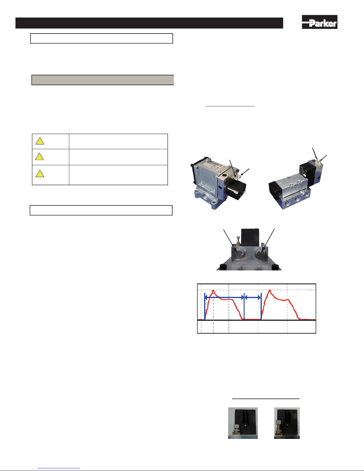
4. How to adjust pulse cycles
ASV2000 ASV5000
ON time adjustment needle
OFF time adjustment needle
ON time adjustment needle
OFF time
adjustment needle
ON time adjustment needleOFF time adjustment needle
ASV13000 & ASV15000
Time
ƐPLQ
Flow
ON time Off time
Only for ASV13000 & 15000: Confirm “Continuous/Pulse
Needle” is fully opened before adjusting pulse cycles.
1) Do not supply air to the unit when adjusting the Continuous/Pulse
Needle
2) The “Continuous/Pulse Needle” should be fully opened by loosing the
needle in CCW direction, and fix its position by a lock nut (Shipment condition).
3) When the “Continuous/Pulse Needle” is fully closed, the main valve
position keeps the “ON” condition and does not create pulsed blow.
Continuous/Pulse needle
ASV13000 & ASV15000
ON (Continuous blow) OFF (Pulse blow)
Operating Manual
Indicates an impeding hazardous situation which may
arise due to improper handling or operation and could
result in serious personal injury or death.
Danger
Warning
Caution
Indicates a potentially hazardous situation which may
arise due to improper handling or operation and could
result in serious personal injury or death.
Indicates a potentially hazardous situation which may
arise due to improper handling or operation and could
result in personal injury or property-damage-only
accidents.
!
!
!
Thank you for your choice of Parker product. Please read this operating
manual carefully and use the product correctly. Keep this operating
manual in case questions arise about this product in the future. If this
operating manual becomes unreadable or lost, consult our distributors
or Parker sales offices.
*1 ISO 4414: Pneumatic fluid power recommendations for the application of
equipment to transmission control system
For Safety Use
The following safety precautions are provided to prevent damage and
injury to personnel and to provide instructions on the correct usage of
this product. These precautions are classified into 3 categories:
“CAUTION” , ” WARNING” , and “DANGER” according to the
severity of possible injury or damage and the likelihood of such injury
or damage. Be sure to comply with all precautions. Also comply with
safety regulations such as ISO 4414(*1), Industrial Safety and Health
Law, and High Pressure Gas Safety Law.
9IM-V075-
a
www.comoso.com
Page 2
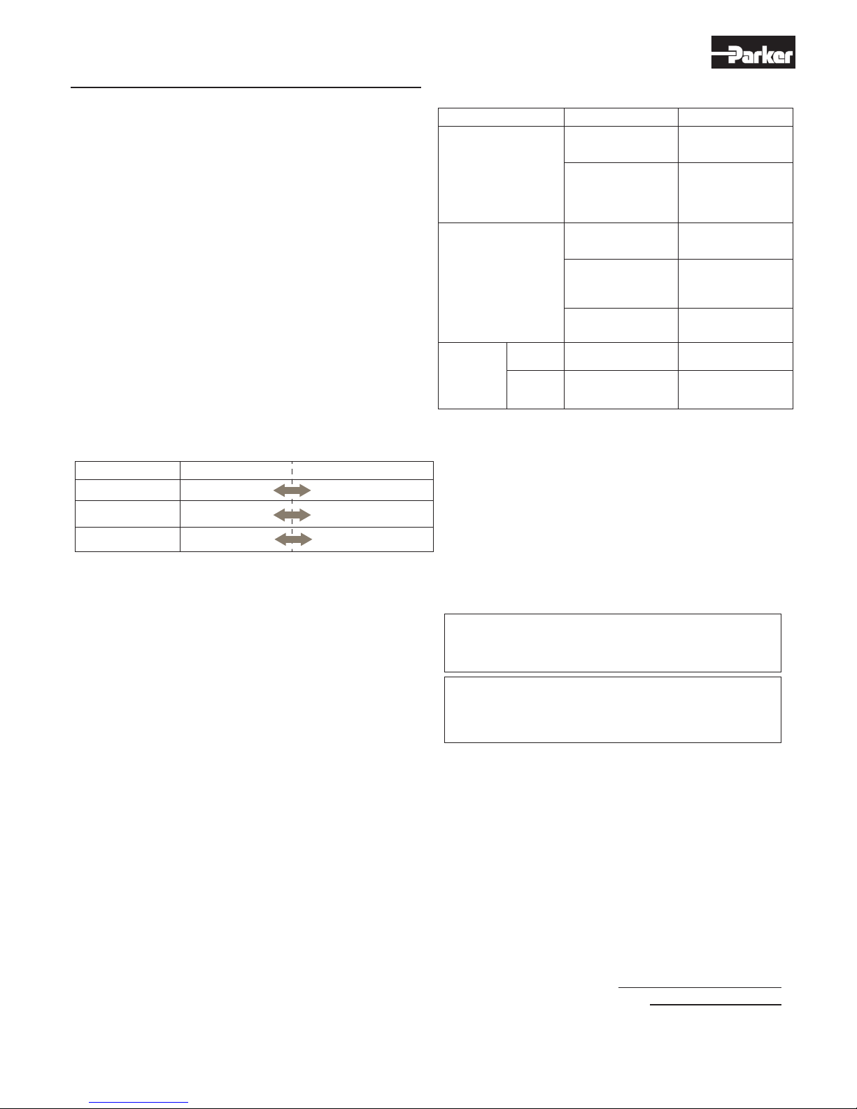
ON time adjustment
needle
Tighten (Clockwise)
Slow
Longer ON time
Longer OFF time
Loosen (Counter clockwise)
Fast
Shorter ON time
Shorter OFF time
Pulsed air cycle
OFF time adjustment
needle
*Adjust frequency of pulsed air to less than5Hz (ASV2000&ASV5000),
0.1~1Hz (ASV13000&15000). If frequency of pulsed air is higher than 5 Hz,
(ASV2000&ASV5000),1Hz (ASV13000&ASV15000), operation of the
pneumatic circuit (logistic element) may become unstable.
Caution
When air blow is not desired, be sure to cut air supply to the Air Saver Unit.
Air blow may come out even the ON/OFF time adjustment needles are fully
tightened. This unit is not designed to be an “OFF” valve.
5. Notes for usage
A)Before piping
Thoroughly flush the inside of any pipes to remove chips, coolant,
dust and etc.
B) Air quality
$LU6DYHUUHTXLUHVDQDLUILOWHUZLWKILOWUDWLRQRIȝPRUILQHU
2) If it is difficult to make filter drain management periodically, Parker
recommends setting up an air filter with automatic drain mechanism.
3) Be sure to take proper maintenance for a compressor. If sludge
produced in compressor oil enters pneumatic equipment, it will cause
operation failure of pneumatic equipment. Parker recommends setting
up a coalescing filter after a filter.
C) Pneumatic circuit
This unit is external pilot operated valve. To avoid malfunctions due
to pressure drops, the external pilpt air supply pressure must be more
than 3 bar at all times. To avoid pressure drops during air blowing
process, set up relatively higher supply pressure and use tubes with
proper diameter.
D) Stopping the air blow
Be sure to cut air supply to Air Saver Unit when air blow is not used.
Blown air may come out even if the ON/OFF time adjustment needles
are fully tightened.
E) Lubrication
This product does not require lubricated air.
Please do not lubricate it.
6. Failure and trouble shooting
a) Failure and countermeasure
Failure condition
Cause Countermeasure
The unit cannot be operated.
Operating frequency is
getting slower.
Supply air might be less
than 3 bar during
operation.
Adjust supply air
pressure properly.
Substantial air
leakage is
observed.
From main
valve part
From base
gasket
Valve part is contaminated
with dust or sludge.
Dust or high viscosity oil
is trapped in the valve
and it obstructs the spool.
Contaminant is caught
inside of the pneumatic
circuit, and it blocks up
the flow.
Contaminant accumulated
in the exhaust port,
obstructing the air flow.
Spool seal rings are
damaged.
Tightening torque for
mounting screws is not
enough to mount valve.
1)Replace the product.
2)If an air filter is not
used, use an air filter.
3)If problem is sludge,
use a coalescing filter.
1)Replace the product.
2)If air filter is not used,
use an air filter.
Replace the logic
element.
Clean air mufflers or
replace them.
Replace the master valve.
Tighten mounting screws
to appropriate torque.
7. Maintenance and disassembly
Regarding repair and maintenance, please consult Parker.
As a general rule, do not attempt maintenance or disassemble.
If it is absolutely necessary to do maintenance work, keep the following
points in mind.
1) Make sure that the actuators such as cylinders will not cause damage
if they move.
2) Cut off electricity.
3) Cut off pneumatic pressure and exhaust air in the line.
4) Clean up the surroundings of the valve.
Caution
Preparation for air supply and adjustment of pulse time
1) After piping to Air Saver Unit and while the supply air is shut off, fully
close the ON time adjustment needle (clockwise rotation) and fully loosen
the OFF time adjustment needle (counter clockwise rotation).
There are dots on the screw heads of adjustment needles. Please use
the dots for position indication of ON/OFF adjustment.
2) Turn on air to the supply port, air should pass to the output port
continuously.
3) Slowly loosen the ON time adjustment needle in CCW direction.
A pulsed air blow with short OFF time will start. It is suggested to stop
rotating the ON time adjustment needle at around 3 turns (for ASV2000),
2 turns (for ASV5000), or 1.5 turns (for ASV13000&15000) in CCW
direction.
4) ASV2000&ASV5000:
Next, adjust the OFF time by slowly tightening the OFF time adjustment
needle in CW direction. The OFF time of the pulsed air blow will get longer.
Stop rotating the OFF time adjustment needle at around 7 turns (for
ASV2000) or 5 turns (for ASV5000). This should result in about 50%
ON/OFF duty of pulsed air blow at 1.5Hz (ASV2000) or 2Hz(ASV5000).
ASV13000&15000:
Close OFF time adjustment needle fully by screwing the needle in CW
direction. Then, slowly loosen about 2 turns in CCW direction. This
should result in about 1Hz and 50% duty pulsed air blow.
5) Use the procedure of 4) as a starting point, and make the frequency
and duty adjustments required in your application by using the ON time
and OFF time adjustment needles.
6) Fix the adjustment position by tightening lock nuts on adjustment screws.
Note
Any request of after-service or maintenance parts, please contact our
distributors or Parker customer service. Keep this operation manual.
This operation manual would be changed without notice. Please check
the newest version.
Any attempt to repair and/or disassembling of the product by the user violates
the warranty and Parker does not take any responsibility for damage and
injury caused by it.
Kuroda Pneumatics Ltd
(Parker Hannifin Automation Division Japan)
10243 Kamakazu, Asahi city, Chiba 289-2505, Japan
http://www.parkerkuroda.com
http://www.parker.com
www.comoso.com
 Loading...