

Page 1
Safety Warning!
!!
High-performance motion control equipment is capable of producing rapid movement and
very high forces. Unexpected motion may occur especially during the development of controller
programs. KEEP WELL CLEAR of any machinery driven by servo motors. Never touch any part
of the equipment while it is in operation.
This product is sold as a motion control component to be installed in a complete system
using good engineering practice. Care must be taken to ensure that the product is installed and
used in a safe manner according to local safety laws and regulations. In particular, the product
must be positioned so that no part is accessible while power may be applied.
This and other information from Parker Hannifin Corporation, its subsidiaries, and authorized
distributors provides product or system options for further investigation by users having technical expertise. Before you select or use any product or system, it is important that you analyze
all aspects of your application and review the information concerning the product in the current
product catalog. The user, through its own analysis and testing, is solely responsible for making
the final selection of the system and components and assuring that all performance, safety, and
warning requirements of the application are met.
If the equipment is used in any manner that does not conform to the instructions given in this
user guide, then the protection provided by the equipment may be impaired.
Product Type . . . . . . . . . . . . . . . . . Aries AR-04CE, AR-08CE, and AR-13CE
The above equipment conforms with the protection requirements of Council Directive
89/336/EEC (EMC Directive) as amended by Directive 92/31/EEC on the approximation of the
laws of the Member States relating to Electromagnetic Compatibility when installed, operated,
and maintained as intended. Also, the above equipment conforms with the requirements of
Council Directive 73/23/EEC (Low Voltage Directive) as amended by 92/59/EEC, and CE
Marking Directive 93/68/EEC, provided the installation requirements described in the
Aries-ACR Drive/Controller Hardware Installation Guide are met, when installed, operated,
and maintained as intended.
In accordance with IEC 61800-3:1997 (adjustable-speed electrical power drive systems) this
product is of the restricted sales distribution class which meets the needs of an industrial
environment when installed as directed. However, further measures may need to be taken for
use of the product in a domestic environment.
The installation requirements are detailed in the Information supplied with the equipment. The
equipment is sold only to competent system builders.
Quick Reference Guide
Aries AR-04CE, AR-08CE, and AR-13CE Servo Drive/Controllers
Aries
Controller
Electromechanical Division
Parker Hannifin Corporation
p/n 88-028905-01A
Effective: October 2007
http://www.parkermotion.com
Compliance
UL Recognized Component, 508c
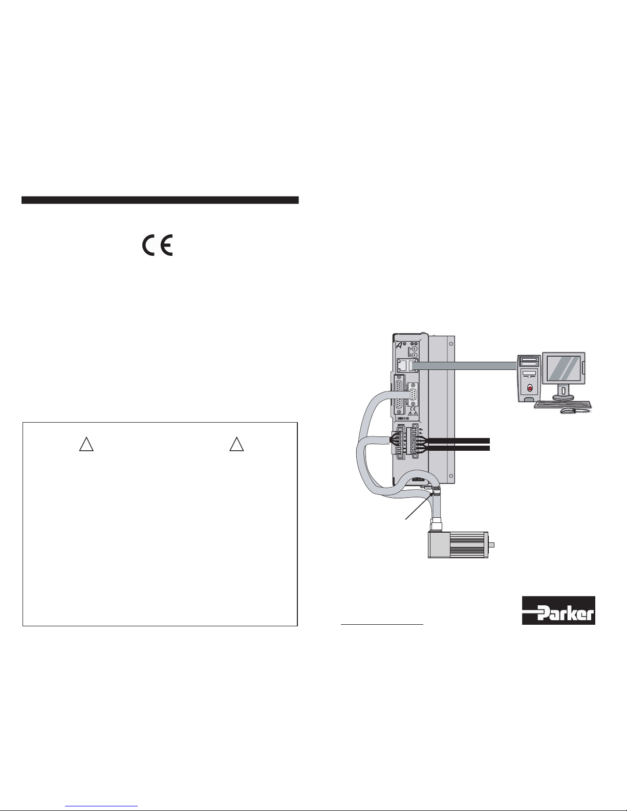
Aries Controller
Control Power
Cable
Motor Power
Mains Cable
Motor Feedback
Cable
Motor
Cable
R-Clamp snugly
attached to braided
shield
Motor
Ethernet Cable
Customer PC
Page 2
Aries
Controller
•
•
•
Warning!
You must connect the unit’s protective conductor
terminal, marked with the earth symbol , to a reliable
system Protective Earth.
The unit’s connector strip terminals are at hazardous
voltages when power is applied to the Aries Controller,
and up to several minutes after power is removed.
Lower voltages may still be present for several minutes
after power is removed.
During normal operation, these high voltage terminals
must not be accessible to the user.
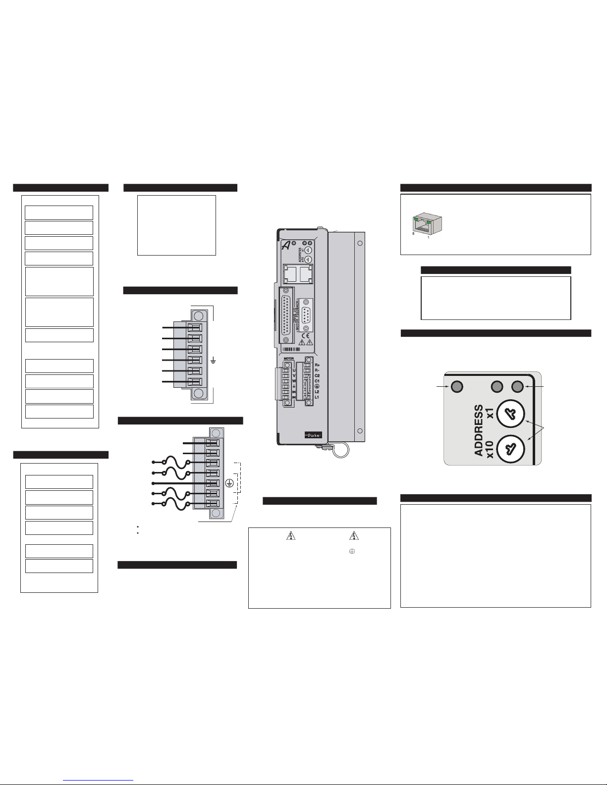
Output Power Connector
MOTOR
BK
BK
W
V
U
Motor Brake Relay
Motor Brake Relay
Motor Safety Earth
Motor Phase
Motor Phase
Motor Phase
Power Supply
120/240 VAC, 50-60Hz, single phase
Drive Controller Status LEDs
Drive Enabled
Off
Yellow (flashes in Regen)
Yellow/Green (alternating)
Drive Disabled
Off
Yellow
Yellow
Yellow & 1 Green flash
Yellow & 2 Green flashes
Yellow & 3 Green flashes
Yellow & 4 Green flashes
Green
Green
Green
Red
Off
Red
Red
Red
Red
Red
Enabled
Regeneration active
Autorun mode
No faults, or Ethernet boot (8 sec)
Motor control boot (4 sec
)
No bridge power
Bridge fault
Feedback fault
Thermal fault
Other fault
LED State
—
Left
Right What it means
Fuse Information
Aries Controller has no internal fuses. For safety,
you must provide a fuse in each of the AC input
lines. See the installation guide for detailed fuse
information.
Factory installed jumpers
C1 to L1
C2 to L2
Remove jumpers to use separate control
and motor mains AC power input.
R+
R-
C2
C1
L2
L1
Protective Earth GND
Control Input Power
Control Input Power
External Regeneration Resistor
External Regeneration Resistor
Motor Input Power
Motor Input Power
Mains Power Connector
Ethernet Connector
RX+ 1
RX– 2
TX+ 3
Not used 4
Not used 5
TX– 6
Not used 7
Not used 8
Signal
Pin
Ethernet Cable: Use braid over foil twisted-pair
wiring (straight or crossover).
IP Address Switches
The unit’s IP address is 192.168.100.xx, with the last octet xx set with the rotary
decimal switches. For example: to set to 14, rotate x10 switch to 1 and x1 switch
to 4. Valid range is 01 to 99; 00 is not valid. (Set the IP address of your PC to
192.168.100.yyy, where yyy ≠ xx.)
Ethernet Network Status LED
Off
Green
Red
Red/Green
LED State
Reset or not active
TCP connection on Port 5002 or 5006
UDP connection on Port 5003
Alternating; UDP & TCP connection active
What it means
Ethernet Status LEDs
Ethernet Link/Activity
Ethernet Speed
Off
Yellow
Yellow, flashing
Off
Green
No Ethernet link detected
Ethernet link established;
no activity
Ethernet link established
and active
Ethernet 10Mbps
Ethernet 100Mbps
LED
State What it means
Signal Pin
Motor Feedback Connector
*When using the SinCos protocol, pins
9 and 13 require twisted pair wiring.
ENC Z+/DATA+ 1
ENC Z–/DATA– 2
DGND 3
+5 VDC (250mA max) 4
+5 VDC (250mA max) 5
DGND 6
ENC A–/SIN– 7
ENC A+/SIN+ 8
Hall 1/SCLK+ * 9
Thermal+ 10
Thermal– 15
ENC B–/COS– 11
ENC B+/COS+ 12
Hall 2/SCLK– * 13
Hall 3 14
NOTE: Box surrounding pins indicates
a requirement for twisted-pair wiring.
Pin
I/O Connector
Signal
Input 0+
1
Input 0– 14
Input 1+
2
Input 1– 15
Input 2+
3
Input 2– 16
High-Speed Input 4+ 4
High-Speed Input 4– 17
High-Speed Input 5+ 5
High-Speed Input 5– 18
High-Speed Input 6+ 6
High-Speed Input 6– 19
Input 3+ 7
Input 3– 20
Reserved (future 5V) 8
Reserved (future GND) 21
Output 32+ 9
Output 32– 22
Output 33+ 10
Output 33– 23
Output 34+ 11
Output 34– 24
Output 35+ 12
Output 35– 25
Not used 13
(or Aux Enc A+)
(or Aux Enc A-)
(or Aux Enc B+)
(or Aux Enc B-)
0
1
2
3
4
5
6
7
8
9
0
1
2
3
4
5
6
7
8
9
Ethernet
Network
Status
Drive
Controller
Status
Address
Switches
See the Aries Controller Hardware Installation Guide, Chapter 4, for more
information on how to set IP addresses for the Aries Controller and PC.
 Loading...