

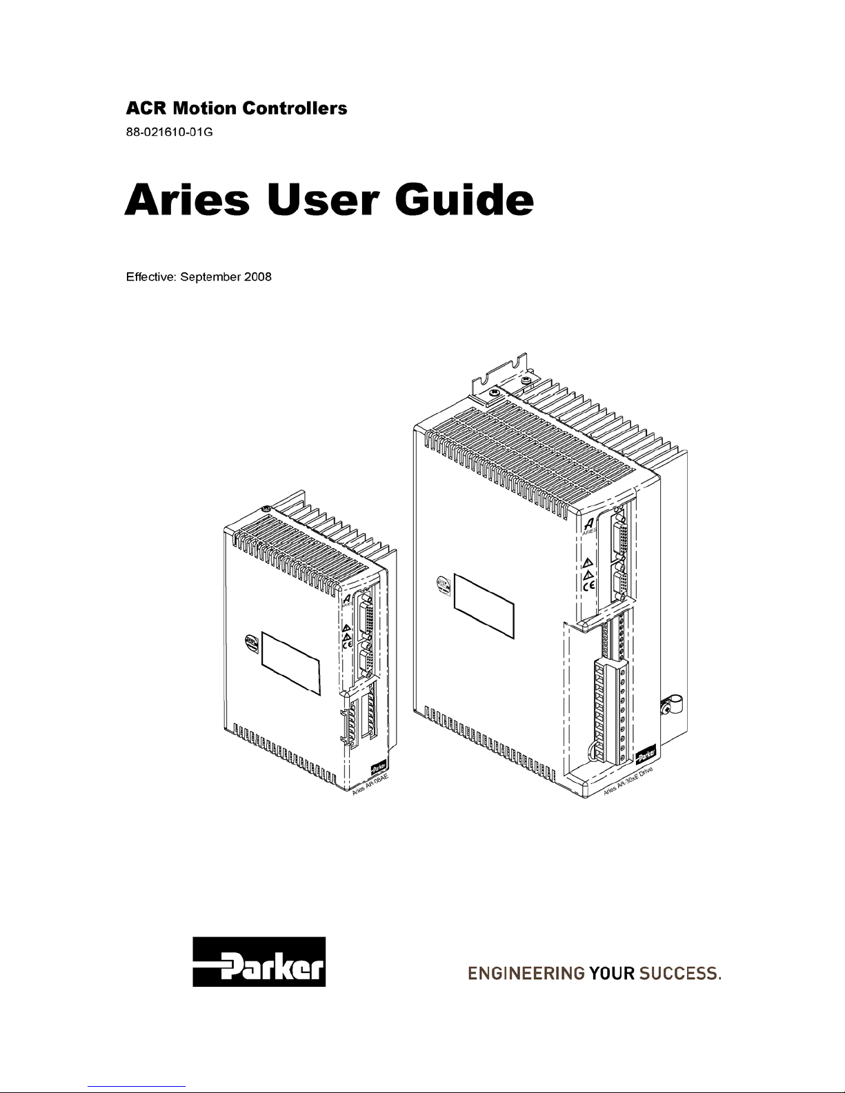
Page 1
Page 2
Parker Hannifin
User Information
Warning — Aries Series products are used to control electrical and mechanical
components of motion control systems. You should test your motion system for
safety under all potential conditions. Failure to do so can result in damage to
equipment and/or serious injury to personnel.
Aries Series products and the information in this user guide are the proprietary property of Parker
Hannifin Corporation or its licensers, and may not be copied, disclosed, or used for any purpose
not expressly authorized by the owner thereof.
Since Parker Hannifin constantly strives to improve all of its products, we reserve the right to
change this user guide and software and hardware mentioned therein at any time without notice.
In no event will the provider of the equipment be liable for any incidental, consequential, or
special damages of any kind or nature whatsoever, including but not limited to lost profits arising
from or in any way connected with the use of the equipment or this user guide.
© 2008 Parker Hannifin Corporation
All Rights Reserved
Technical Assistance
Contact your local automation technology center (ATC) or distributor.
North America and Asia
Parker Hannifin
5500 Business Park Drive
Rohnert Park, CA 94928
Telephone: (800) 358-9070 or (707) 584-7558
Fax: (707) 584-3793
Email: [email protected]
Internet: http://www.parkermotion.com
Europe (non-German speaking)
Parker Hannifin plc
Electromechanical Automation, Europe
Arena Business Centre
Holy Rood Close
Poole
Dorset, UK
BH17 7BA
Telephone: +44 (0) 1202 606300
Fax: +44 (0) 1202 606301
Email: [email protected]
Internet: http://www.parker-emd.com
Germany, Austria, Switzerland
Parker Hannifin
Postfach: 77607-1720
Robert-Bosch-Str. 22
D-77656 Offenburg
Telephone: +49 (0) 781 509-0
Fax: +49 (0) 781 509-176
Email: [email protected]
Internet: http://www.parker-emd.com
Italy
Parker Hannifin
20092 Cinisello Balsamo
Milan, Italy via Gounod, 1
Telephone: +39 02 6601 2478
Fax: +39 02 6601 2808
Email: [email protected]
Internet: http://www.parker-emd.com
Technical Support E-mail
2 Aries User Guide
Page 3

Parker Hannifin
Table of Contents
User Information............................................................................................................................ 2
Table of Contents .......................................................................................................................... 3
Table of Tables............................................................................................................................... 5
Table of Figures............................................................................................................................. 7
Important User Information........................................................................................................ 11
Change Summary .................................................................................................................... 12
Chapter 1 Introduction................................................................................................................16
Aries Products—Overview ....................................................................................................... 17
Compatible Parker Products .................................................................................................... 18
Checking Your Shipment.......................................................................................................... 19
Illustrations in this Installation Guide ........................................................................................ 20
Assumptions of Technical Experience ..................................................................................... 20
Technical Support .................................................................................................................... 20
Chapter 2 Mechanical Installation.............................................................................................. 21
Environment & Drive Cooling ................................................................................................... 22
Dimensions............................................................................................................................... 28
Weight ...................................................................................................................................... 30
Mounting Guidelines................................................................................................................. 31
Chapter 3 Electrical Installation................................................................................................. 32
Installation Safety Requirements.............................................................................................. 33
System Installation Overview ................................................................................................... 34
Power Supply ........................................................................................................................... 39
Multiple Drive Installations........................................................................................................ 48
Brake Relay (Optional) ............................................................................................................. 50
Regeneration Protection........................................................................................................... 54
LEDs⎯Drive Status Indicators................................................................................................. 56
Connector Descriptions ............................................................................................................ 57
Installation Test ........................................................................................................................ 72
Chapter 4 Communications........................................................................................................ 73
RS-232/485 Communications .................................................................................................. 74
Chapter 5 Tuning......................................................................................................................... 78
Servo Tuning Overview ............................................................................................................ 79
Position Variable Overview ...................................................................................................... 80
Servo Response Overview....................................................................................................... 81
Servo System Gains................................................................................................................. 83
Servo Tuning Example ............................................................................................................. 86
Auto-Tuning.............................................................................................................................. 90
Chapter 6 Command Reference................................................................................................. 91
Aries Communications Set-up.................................................................................................. 92
Description of Format ............................................................................................................... 92
Syntax – Letters and Symbols.................................................................................................. 93
Syntax – General Guidelines.................................................................................................... 94
Command Descriptions ............................................................................................................ 95
Chapter 7 Troubleshooting....................................................................................................... 156
Troubleshooting Guidelines.................................................................................................... 157
LEDs⎯Drive Status Indicators............................................................................................... 158
3
Page 4

Parker Hannifin
RS-232/485 Communication Problems.................................................................................. 159
Error Messages ...................................................................................................................... 160
Smart Encoders...................................................................................................................... 163
Hall Sensor Configuration/Troubleshooting ........................................................................... 164
Appendix A Additional Specifications .................................................................................... 168
Amplifier.................................................................................................................................. 169
Feedback................................................................................................................................ 169
Protective Circuits .................................................................................................................. 170
Cables .................................................................................................................................... 173
Appendix B External Power-Dump Resistor Selection.......................................................... 174
External Power-Dump Resistor Selection .............................................................................. 175
Simplified Resistor Selection.................................................................................................. 175
Calculating Resistance—Rotary Motors ................................................................................ 177
Resistor Specifications⎯Rotary Motors................................................................................. 181
Calculating Resistance—Linear Motors ................................................................................. 183
Resistor Specifications⎯Linear Motors ................................................................................. 187
Appendix C Regulatory Compliance–UL and CE................................................................... 189
System Installation Overview ................................................................................................. 190
Regulatory Agencies .............................................................................................................. 200
Standards of Compliance ....................................................................................................... 200
Appendix D Servo Tuning Flow Diagram................................................................................ 201
Servo Tuning Flow Diagram................................................................................................... 202
Appendix E VM26 Expansion Module ..................................................................................... 203
Overview................................................................................................................................. 204
Index ........................................................................................................................................... 205
4 Aries User Guide
Page 5

Parker Hannifin
Table of Tables
Table 1 Output Power Level..................................................................................................... 18
Table 2 Ship Kit Items, AR-01xx through AR-13xx .................................................................. 19
Table 3 Ship Kit Items, AR-20xE and AR-30xE ....................................................................... 19
Table 4 Environmental Specifications, AR-01xx through AR-08xx, AR-20xE and AR-30xE... 23
Table 5 Environmental Specifications, AR-13xx ...................................................................... 23
Table 6 AR-02xx Power Dissipation......................................................................................... 24
Table 7 AR-08xx Power Dissipation......................................................................................... 25
Table 8 AR-13xx Power Dissipation......................................................................................... 26
Table 9 AR-30xE Power Dissipation ........................................................................................ 27
Table 10 AR-01xx and AR-02xx Drive Dimensions ................................................................. 28
Table 11 AR-01xx , AR-02xx, & AR-13xx Drive Dimensions ................................................... 29
Table 12 AR-20xE and AR-30xE Drive Dimensions ................................................................ 30
Table 13 Drive Weight.............................................................................................................. 30
Table 14 Motor Power Fuse Information.................................................................................. 41
Table 15 Fuse Part Numbers ................................................................................................... 42
Table 16 Drive Motor Power Inrush Current ............................................................................ 42
Table 17 Output Power-Continuous and Peak......................................................................... 43
Table 18 Wiring to Motors ........................................................................................................ 44
Table 19 AR-20xE & AR-30xE DC Link Inductors ................................................................... 45
Table 20 Brake Relay Operation .............................................................................................. 53
Table 21 Regeneration Absorption .......................................................................................... 55
Table 22 LED Status Indicator-Normal Operation.................................................................... 56
Table 23 LED Status Indicator-Internal Drive Fault.................................................................. 56
Table 24 MOTOR FEEDBACK Connector Pinout........................................................................... 63
Table 25 Inputs—Encoder Inputs Electrical/Timing Characteristics ........................................ 63
Table 26 MOTOR FEEDBACK Connector Pinout for Resolver Option .......................................... 66
Table 27 Resolver excitation .................................................................................................... 66
Table 28 Fault Output Operation.............................................................................................. 67
Table 29 DRIVE I/O Connector Pinout ........................................................................................ 69
Table 30 Inputs—Enable and Reset Electrical/Timing Characteristics.................................... 70
Table 31 Outputs—Encoder Outputs Electrical/Timing Characteristics................................... 70
Table 32 Outputs— Fault outputs Electrical/Timing Characteristics........................................ 70
Table 33 Inputs—Step & Direction Electrical/Timing Characteristics ...................................... 71
Table 34 Inputs—Analog Electrical/Timing Characteristics ..................................................... 71
Table 35 Terminal Emulator Configuration for RS-232/485 Communication........................... 74
Table 36 RS-232 Connector Pinout ......................................................................................... 75
Table 37 RS-485 Connector Pinout ......................................................................................... 75
Table 38 Position Response Types ......................................................................................... 82
Table 39 Commands-Description of Format ............................................................................ 92
Table 40 Commands-Syntax.................................................................................................... 93
Table 41 Syntax Guidelines ..................................................................................................... 94
Table 42 Configuration Errors and Warnings......................................................................... 100
Table 43 Current Foldback Ratings ....................................................................................... 102
Table 44 Drive Control Mode ................................................................................................. 104
Table 45 Peak Current Rating for Aries Drives ...................................................................... 109
Table 46 Error Status⎯Text Based Report ........................................................................... 131
Table 47 Error Log⎯Enable/Disable ..................................................................................... 132
Table 48 Terminal Emulator Configuration for RS-232/485 Communication......................... 159
Table 49 Communications Port Errors and Resolutions ........................................................ 160
Table 50 Error Messages ....................................................................................................... 163
Table 51 Configuring Hall Sensors......................................................................................... 167
Table 52 LED Short Circuit Fault............................................................................................ 170
5
Page 6

Parker Hannifin
Table 53 LED Drive Over-Temperature Fault ........................................................................ 170
Table 54 Reset Temperature Values ..................................................................................... 171
Table 55 LED Under-Voltage Fault ........................................................................................ 171
Table 56 LED Over-Voltage Fault .......................................................................................... 172
Table 57 Simplified Selection of External Power-Dump Resistor .......................................... 176
Table 58 Drive Capacitor Absorption ..................................................................................... 179
Table 59 Drive Capacitor Absorption ..................................................................................... 185
Table 60 Control Power Filter Selection................................................................................. 194
Table 61 Mains Motor Power Filter Selection ........................................................................ 194
Table 62 Enclosure Mounting Clamps ................................................................................... 196
Table 63 Regulatory Agencies ............................................................................................... 200
6 Aries User Guide
Page 7

Parker Hannifin
Table of Figures
Figure 1 Cabinet Losses for AR-02xx when connected to a Parker BE231D motor ............... 24
Figure 2 Cabinet losses for AR-08xx when connected to a Parker BE343J motor ................. 25
Figure 3 Cabinet losses for AR-13xx when connected to a Parker MPM1421CSJ motor....... 26
Figure 4 Cabinet losses for AR-30xE when connected to a Parker MPM1422CSJ motor ...... 27
Figure 5 Drive mounting for the AR-01xx & AR-02xx............................................................... 28
Figure 6 Drive mounting for the AR-04xx, AR-08xx, and AR-13xx .......................................... 29
Figure 7 Drive mounting for the AR-20xE and AR-30xE.......................................................... 30
Figure 8 Panel Layout Dimensions for Aries Drives................................................................. 31
Figure 9 Overview of System Installation for AR-01xx to AR-13xx.......................................... 34
Figure 10 AR-01xx to AR-13xx Factory Installed Jumpers ...................................................... 35
Figure 11 Overview of System Installation for AR-20xE & AR-30xE ....................................... 36
Figure 12 AR-20xE to AR-30xE Factory Installed Jumpers..................................................... 37
Figure 13 Connectors on Aries Models AR-01xx to AR-13xx .................................................. 38
Figure 14 Connectors on Aries Models AR-20xE & AR-30xE ................................................. 38
Figure 15 Input Power Requirements ...................................................................................... 39
Figure 16 Motor and Control Mains Power Supply Connection ............................................... 40
Figure 17 Output Power Connection........................................................................................ 44
Figure 18 External DC Link Inductor Connection..................................................................... 45
Figure 19 Mains Control Input Power....................................................................................... 47
Figure 20 Multiple Drives AR-01xx to AR-13xx: Single Point Safety Earth ............................. 48
Figure 21 Multiple Drives AR-20xE & AR-30xE: Single Point Safety Earth ............................. 49
Figure 22 Typical Brake Relay Connection.............................................................................. 50
Figure 23 Brake Relay Connection for Parker Motors ............................................................. 51
Figure 24 Brake Relay Connection for Non-Parker Motors ..................................................... 52
Figure 25 External Regeneration Connection .......................................................................... 54
Figure 26 Mains/Input Power Connector.................................................................................. 57
Figure 27 Output (MOTOR) Power Connector ........................................................................... 59
Figure 28 AR-20xE & AR30xE Control Connector ................................................................... 61
Figure 29 MOTOR FEEDBACK connector, female drive connector pinout.................................... 62
Figure 30 MOTOR FEEDBACK connector, internal circuit diagram............................................... 62
Figure 31 MOTOR FEEDBACK connector, female drive connector pinout.................................... 65
Figure 32 MOTOR FEEDBACK connector for resolver option, internal circuit diagram................. 65
Figure 33 DRIVE I/O connector, female drive connector pinout ................................................. 67
Figure 34 DRIVE I/O connector, internal circuit diagram ............................................................ 68
Figure 35 RS-232/485 Connections......................................................................................... 74
Figure 36 RS-485 Multi-drop Connections............................................................................... 76
Figure 37 Closed Loop and Open Loop System Comparison ................................................. 79
Figure 38 Commanded Position............................................................................................... 80
Figure 39 Integrator Windup (Without Using SGILIM Command)........................................... 84
Figure 40 Integrator Windup (using the SGILIM Command)................................................... 85
Figure 41 Clockwise/ Counter-clockwise rotation .................................................................... 99
Figure 42 Time until current foldback occurs ......................................................................... 102
Figure 43 Linear motor track .................................................................................................. 103
Figure 44 Notch Filter Topology............................................................................................. 120
Figure 45 Notch Filter Magnitudes ......................................................................................... 120
Figure 46 Notch Filter A ......................................................................................................... 121
Figure 47 Notch Lead Filter Break Frequency ....................................................................... 123
Figure 48 Clockwise/ Counter-clockwise rotation .................................................................. 154
Figure 49 Hall Connection Diagram ....................................................................................... 165
Figure 50 Motor Terminal Voltages (back EMF) and Hall Sensor Signals............................. 167
Figure 51 Time until current foldback occurs ......................................................................... 173
Figure 52 360° Bonding Techniques...................................................................................... 193
7
Page 8

Parker Hannifin
Figure 53 Typical LVD/EMC Installation, AR-02xx to AR-13xx.............................................. 197
Figure 54 Typical LVD/EMC Installation, AR-20xE & AR-30xE ............................................. 198
Figure 55 Panel Layout Dimensions for the Aries Drive ........................................................ 199
Figure 56 Servo Tuning Flow Diagram .................................................................................. 202
Figure 57 VM26 Breakout Module.......................................................................................... 204
8 Aries User Guide
Page 9

Parker Hannifin
Product Type........................................... Aries Family AR-01Ax, 02Ax, 04Ax,
08Ax, 13Ax, 20AE, and 30AE
................................................................ Aries Family AR-01Sx, 02Sx, 04Sx,
08Sx, 13Sx, 20SE, and 30SE
The above product complies with the requirements of directives:
• EMC Directive 89/336/EEC
• Low Voltage Directive 73/23/EEC
• CE Marking Directive 93/68/EEC
Provided the installation requirements described in this guide are met, and
there are no special requirements of the installation and operating
environment so that the application may be considered typical.
The above equipment conforms with the protection requirements of Council
Directive 89/336/EEC as amended by Directive 92/31/EEC on the
approximation of the laws of the Member States relating to Electromagnetic
Compatibility when installed, operated and maintained as intended. Also: The above equipment conforms with the requirements of Council Directive
73/23/EEC (Low Voltage Directive) as amended by Directive 93/68/EEC (CE
Marking Directive), when installed, operated, and maintained as intended.
In accordance with IEC 61800-3:1997 (Adjustable speed electrical power
drive systems) this product is of the restricted sales distribution class which
meets the needs of an industrial environment when installed as directed.
However, further measures may need to be taken for use of the product in a
domestic environment.
The installation requirements are detailed in the Information supplied with the
equipment. The equipment is sold only to competent system builders.
Compliance is demonstrated by the application of the following standards:
• BS EN 61800-3 (1997) including Amendment A11 Adjustable speed
• BS EN 50081-2 (1994) Electromagnetic compatibility—Generic
• BS EN 61000-6-2 (1999) Electromagnetic compatibility Part 6-2:
• BS EN 61010-1 (1993) including Amendment A2. Safety
electrical Power drive systems Part 3. EMC product standard
including specific test methods.
emission standard Part 2. Industrial Environment.
Generic Standards – Immunity for industrial environments.
requirements for electrical equipment for measurement, control, and
laboratory use. Part 1 General Requirements.
9
Page 10
Parker Hannifin
Warning — Risk of damage and/or personal injury
The Aries drives described in this guide contain no user-serviceable parts.
Attempting to open the case of any unit, or to replace any internal
component, may result in damage to the unit and/or personal injury. This
may also void the warranty.
Symbols Description
Protective Earth Ground
Functional Earth (Ground) Terminal
Shield, Frame, or Chassis Terminal
Caution Risk of Electrical Shock
Caution, Refer to Accompanying Documentation
10 Aries User Guide
Page 11
Parker Hannifin
Important User Information
It is important that motion control equipment is installed and operated in such a way that all
applicable safety requirements are met. It is your responsibility as an installer to ensure that you
identify the relevant safety standards and comply with them; failure to do so may result in
damage to equipment and personal injury. In particular, you should study the contents of this
user guide carefully before installing or operating the equipment.
The installation, set up, test, and maintenance procedures given in this User Guide should only
be carried out by competent personnel trained in the installation of electronic equipment. Such
personnel should be aware of the potential electrical and mechanical hazards associated with
mains-powered motion control equipment—please see the safety warnings below. The individual
or group having overall responsibility for this equipment must ensure that operators are
adequately trained.
Under no circumstances will the suppliers of the equipment be liable for any incidental,
consequential or special damages of any kind whatsoever, including but not limited to lost profits
arising from or in any way connected with the use of the equipment or this guide.
Warning —
movement and very high forces. Unexpected motion may occur especially during the
development of controller programs. KEEP WELL CLEAR of any machinery driven by stepper or
servo motors. Never touch any part of the equipment while it is in operation.
This product is sold as a motion control component to be installed in a complete system using
good engineering practice. Care must be taken to ensure that the product is installed and used
in a safe manner according to local safety laws and regulations. In particular, the product must
be positioned such that no part is accessible while power may be applied.
This and other information from Parker Hannifin Corporation, its subsidiaries, and authorized
distributors provides product or system options for further investigation by users having technical
expertise. Before you select or use any product or system, it is important that you analyze all
aspects of your application and review the information concerning the product in the current
product catalog. The user, through its own analysis and testing, is solely responsible for making
the final selection of the system and components and assuring that all performance, safety, and
warning requirements of the application are met.
If the equipment is used in any manner that does not conform to the instructions given in this
user guide, then the protection provided by the equipment may be impaired.
The information in this user guide, including any apparatus, methods, techniques, and concepts
described herein, are the proprietary property of Parker Hannifin or its licensors, and may not be
copied disclosed, or used for any purpose not expressly authorized by the owner thereof.
Since Parker Hannifin constantly strives to improve all of its products, we reserve the right to
modify equipment and user guides without prior notice. No part of this user guide may be
reproduced in any form without the prior consent of Parker Hannifin.
High-performance motion control equipment is capable of producing rapid
11
Page 12

Parker Hannifin
Change Summary
Revision G Changes
This document, 88-021610-01G, supersedes 88-021610-1F. Changes
associated with Aries User Guide revisions, and document clarifications and
corrections are as follows:
Topic Description
Electrical Installation
Command Reference
Troubleshooting
Added note to Motor Power Fuse Information
that 40A fuse is recommended regardless of
single- or 3-phase input power.
Added “Yellow & 5 Green (flashing)” for Encoder
Loss to Internal Drive Faults
Corrected connector p/n from ELFA13210E to
OSTTJ075102 for Mains/Input Power Connector
and Motor Connector
Removed reference to 120V motor power for
single- or three-phase AR-20xE in AC Power
Supply Connection.
Added “—Encoder” to clarify title to section Motor
Feedback Connector—Encoder.
Corrected Motor Feedback Connector—Resolver
schematic by removing pins 16 and 17.
Corrected diode connection across motor cable in
drawing in Motors without Full Wave Rectifiers
Corrected “perception” to “misperception” in Servo
Response Overview section, Stability
Added “Warning” to CONFIG
E12 because they are not faults.
Changed start of range for DMPSCL
with info on using DRES command with 0 value.
Changed range maximum to 400 rps for DMTW
DMVLIM
Added E28 to ERROR
link from TOTEMP to TDTEMP.
Added DTHERM to list of commands stored with
ESTORE
Added 3 and 4 to ranges, and additional
information regarding OHALL 1 and OHALL 4 to
OHALL
Added E28 to Error Messages
E34 link from TOTEMP to TDTEMP.
Added “Yellow & 5 Green (flashing)” for Encoder
Loss to Internal Drive Faults
, DMVSCL, and SMVER.
. Alphabetized list.
command.
.
table.
topic.
errors E10, E11, and
to include 0,
command; corrected E34
table; corrected
table.
table
.
,
12 Aries User Guide
Page 13

Parker Hannifin
Revision F Changes
This document, 88-021610-01F, supersedes 88-021610-1E. Changes
associated with Aries User Guide revisions, and document clarifications and
corrections are as follows:
Topic Description
Command Reference
Aries Names
LEDs—Drive Status
Indicators
Resolver option
Error Messages Added E50, E51, and E52 error messages
Additions to ERES, SFB, and TREV commands for
Aries Resolver option.
Added TIDAC and TIQAC commands.
Corrected DCMDZ syntax.
Corrected ranges for DMTIC, DMTIP, DMTKE,
DMTRES, and ERES.
Updated part number descriptions to include
Resolver and Powerlink Options
Updated to include Autorun mode.
Added Motor Feedback Connector pinout, circuit
diagram, and resolver excitation frequency.
Revision E Changes
This document, 88-021610-01E, supersedes 88-021610-1D. Changes
associated with Aries User Guide revisions, and document clarifications and
corrections are as follows:
Topic Description
AC Power Supply
Connection
Drive I/O Connector—
Internal Circuit Diagram
Drive I/O Connector
VM26 Breakout Module
Clarified jumpering two phases of the motor input
power to the control input power allows for a
single AC connection.
Corrected circuit for Step+ and Step-.
Step and Direction is not optically isolated, but is
5V differential compatible (RS-422 logic level
compatible).
Added appendix describing the VM26 Breakout
Module.
13
Page 14

Parker Hannifin
Revision D Changes
This document, 88-021610-01D, supersedes 88-021610-1C. Changes
associated with Aries User Guide revisions, and document clarifications and
corrections are as follows:
Topic Description
Regulatory Compliance Aries is no longer cUL compliant.
Output Power Corrected to 14.07A
Part Number
Environment and Drive
Cooling
In Appendix C, Table 62 Enclosure Mounting
s, corrected part number to read R CLAMP
Clamp
KIT.
Removed separate Still Air and Moving Air
temperature maximums. Now provides only an
Ambient Air temperature.
Revision C Changes
This document, 88-021610-01C, supersedes 88-021610-1B. Changes
associated with Aries User Guide revisions, and document clarifications and
corrections are as follows:
Topic Description
Models
Regeneration
Protection
DC Inductance Link Enhancement: Added discussion and connections.
Command Reference
Error Messages
Enhancement: Added models AR-13xx, AR-20xE,
and AR-30xE, and relevant information.
Enhancement: Added discussion and connections.
Enhancements: Added the following commands:
ALIGN , DMTSWT, DRES, ENCOFF, ESTORT, IANI,
OHALL, P163
Modified the following commands:
DMTTCM—range
DMTTCW—range
DVMLIM—range and default
DPWM—range and corrected mode information
ERROR—now includes messages E47 and E48
SFB—In OS 2.10 or higher, SFB also functions to
set feedback type
TMTEMP—Added new reporting capabilities for
OS 2.10 or higher
Enhancement: Added error messages E47 and
E48. See Chapter 7 Troubleshooting.
14 Aries User Guide
Page 15

Parker Hannifin
Revision B Changes
This document, 88-021610-01B, supersedes 88-021610-1A. Changes
associated with Aries User Guide revisions, and document clarifications and
corrections are as follows:
Topic Description
Fault Operation
DRIVE I/O connector-
internal circuit diagram
Inputs—Enable and
Reset
Outputs—Encoder
Inputs—Step &
Direction
Inputs--Analog
RS-485 Communication Correction: Both RS-485 channels are Tx/Rx.
Tuning
Command Reference
Enhancement: Added a discussion about fault
operations for the
DRIVE I/O connector.
Correction: Simplified the circuit diagram for the
Enable input.
Enhancement: Added specifications detailing
electrical and timing characteristics on the
/O connector.
I
DRIVE
Enhancement: Added specifications detailing
electrical and timing characteristics on the
/O connector.
I
DRIVE
Enhancement: Added specifications detailing
electrical and timing characteristics on the
I
/O connector.
DRIVE
Enhancement: Added specifications detailing
electrical and timing characteristics on the
/O connector.
I
DRIVE
Enhancements: Added Chapter 5 Tuning,
describing servo tuning.
Added Appendix D Servo Tuning Flow Diagram.
Enhancements: Added the following commands:
DMTD, DMTJ, DNOTAD, DNOTAF, DNOTAQ, DNOTBD,
DNOTBF, DNOTBQ, DNOTLD, DNOTLG, SGVF.
Modified CONFIG—now includes error messages
E13-E18.
Error Messages
Enhancement: Added error messages E13-E18.
See Chapter 7 Troubleshooting.
15
Page 16

Chapter 1 Introduction
CHAPTER ONE
Introduction
IN THIS CHAPTER
Aries Products—Overview.........................................................................17
Compatible Parker Produc
Checking Your Shipment
Illustrations in this Ins
Assumptions of Technic
Technical Support
ts...................................................................... 18
...........................................................................19
tallation Guide .........................................................20
al Experience....................................................... 20
......................................................................................20
Page 17
Parker Hannifin
Aries Products—Overview
The Aries drives are a family of super compact, super efficient digital servo
drives. Their maximum continuous shaft power ranges from 100 Watts to
3000 Watts (3kW). Ready for direct panel mounting, you can select the
precise power level needed for your application.
Aries Product Descriptions
Aries Servo Drives can control the torque, velocity, and position of servo
motors using a digital current loop. Control of Aries Drives is performed using
controllers, which have standard ±10V torque command, ±10V velocity
command, or 5V TTL step & direction interface.
For Aries drives using the analog or step and direction command interface,
configure the drives through RS-232/485 using the Aries Support Tool on a
personal computer (PC), or other standard communication software. For
Aries drives using the Ethernet Powerlink command interface, configure the
drives through Ethernet using the ACR-View software on a PC. Many
advanced features are standard on the product including “plug and play”
capabilities with Aries-compatible motors.
Aries Names
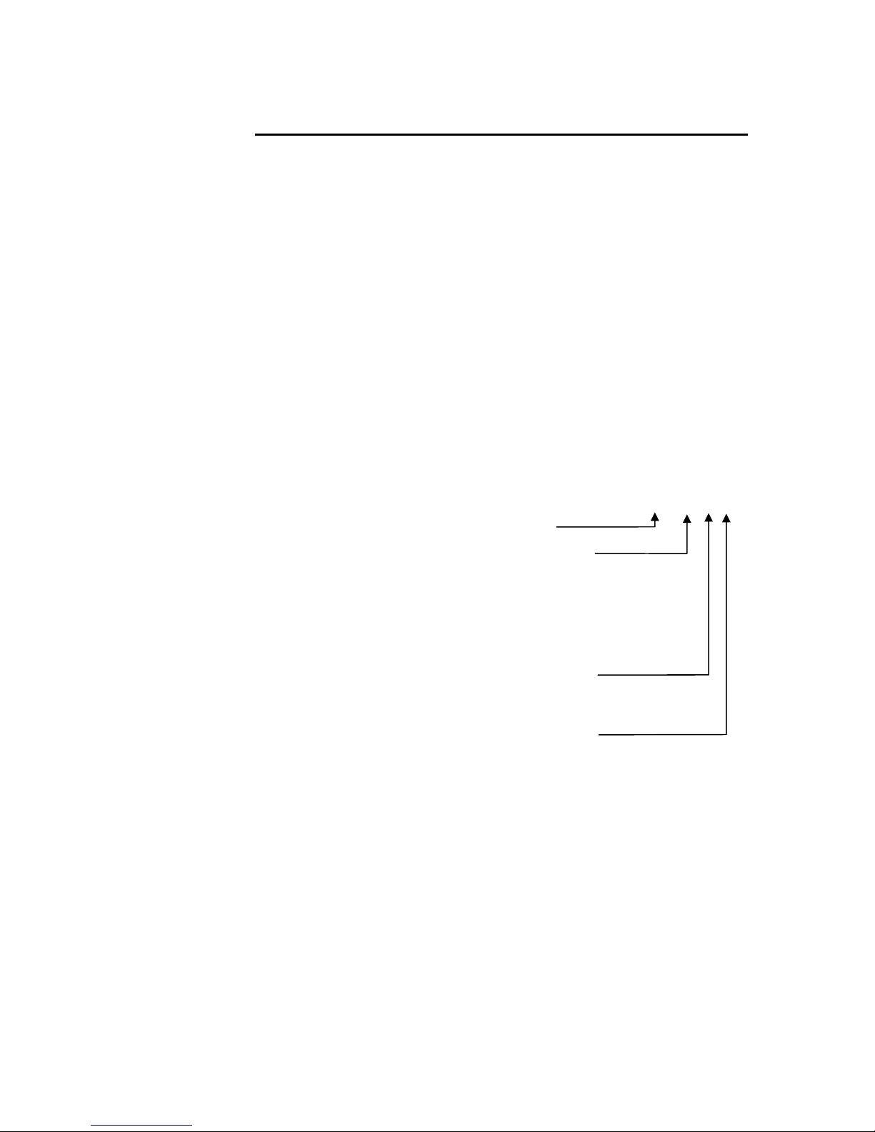
The following diagram explains the Aries part numbers:
Drive Type............................................... Aries
Maximum Shaft Power............................ 01 = 100W
02 = 200W
04 = 400W
08 = 750W
13 = 1300W
20 = 2000W
30 = 3000W
Command Interface ................................A = Analog
S = Step & Direction
P = Ethernet Powerlink
Motor Feedback ......................................E = Encoder
R = Resolver
AR – 01 A E
Input Power
Motor Power
AR-01xx, AR-02xx
AR-04xx, AR-08xx, AR-13xx................... 120/240 VAC single-phase mains
motor power
AR-20xE.................................................. 240 VAC single-phase or three-
phase mains motor power
AR-30xE.................................................. 240 VAC three-phase mains motor
Control Power
AR-01xx through AR-30xE...................... 120/240 VAC single-phase mains
power only
control power
Chapter 1 Introduction 17
Page 18
Parker Hannifin
Output Power Level
Servo Motor Drives
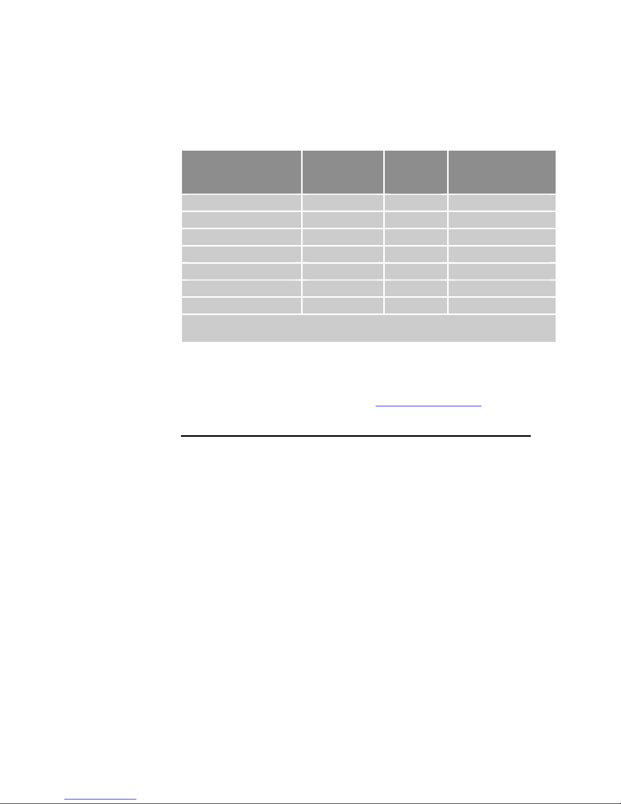
In Table 1, the maximum current is given at 120/240 VAC input, which
equates to a motor bus voltage of 170/340 VDC.
Drive Continuous
Current (RMS)
AR-01xx 1A 3A 100W, 0.13 hp*
AR-02xx 1.75A 5.25A 200W, 0.27 hp*
AR-04xx 3A 9A 400W, 0.53 hp*
AR-08xx 4.50A 13.5A 750W, 1.0 hp*
AR-13xx 6.3A 14.07A 1300W, 1.75 hp*
AR-20xE 10A 30A 2000W, 2.7 hp**
AR-30xE 16A 48A 3000W, 4.04 hp**
* Maximum rating at 240 VAC, single-phase
** Maximum rating at 240 VAC, three-phase
Table 1 Output Power Level
Peak
Current
(RMS)
Continuous Shaft
Output Power
Options
For the latest additions, see our website at www.parkermotion.com.
Compatible Parker Products
Servo Controller
(±10V torque or velocity mode)............... ACR series or other Parker
controller
18 Aries User Guide
Stepper Controller (S&D mode).............. ACR series or other Parker
controller
Software .................................................. Aries Support Tool
For information about cables, motors, etc., see “Chapter 2 Mechanical
Ins
tallation”.
Page 19
Parker Hannifin
Checking Your Shipment
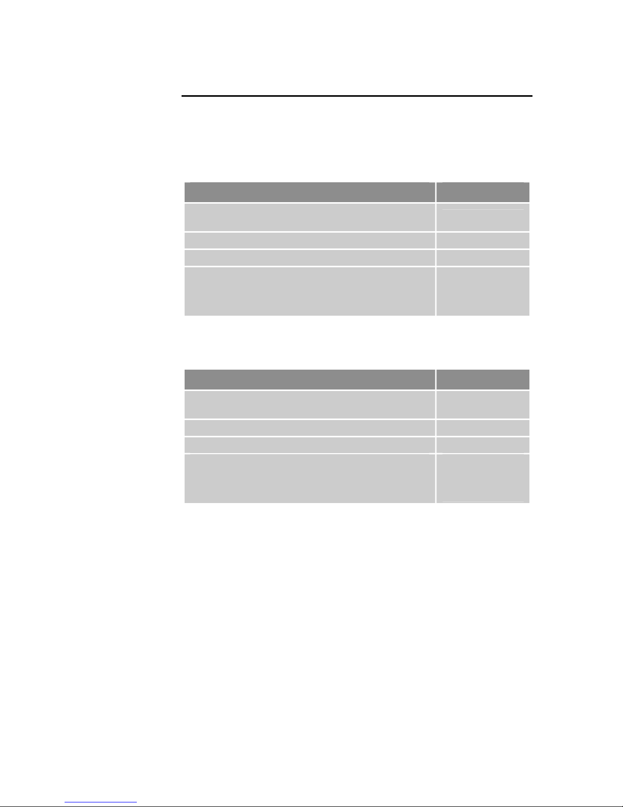
Inspect your shipment carefully. You should have received the corresponding
ship kit along with your drive.
Ship Kit Items
The following items ship with the AR-01xx through AR-13xx drives:
Part Part Number
Aries Quick Reference Guide
AR-01xx AR-02xx, AR-04xx, AR-08xx, & AR-13xx
R-Clamp 52-019734-01
Screw (8-32 3/8 inch) 51-006055-01
Aries compact disc containing the following:
• Aries Hardware Installation Guide
• Aries Support Tool
Table 2 Ship Kit Items, AR-01xx through AR-13xx
88-021594-01C
88-021610-01
Part number N/A
The following items ship with the AR-20xE and AR-30xE drives:
Part Part Number
Aries Quick Reference Guide
AR-20xE and AR-30xE
R-Clamp 50-018127-01
Screw (8-32 3/8 inch) 51-006055-01
Aries compact disc containing the following:
• Aries Hardware Installation Guide
• Aries Support Tool
Table 3 Ship Kit Items, AR-20xE and AR-30xE
88-025222-01A
88-021610-01
Part number N/A
Motors
You may have ordered a motor from one of the following families of Parker
motors:
• SE/SM Series • LXR Linear Series
• BE Series • SL Linear Series
• NeoMetric Series • ILM Linear Series
• J Series • SME Series
• MaxPlus Rotary • SMN Series
• MaxPlus Linear
Chapter 1 Introduction 19
Page 20

Parker Hannifin
Illustrations in this Installation Guide
Typically, the illustrations in this guide show the Aries AR-01xx and the
AR-30xE. These two models represent other models with similar features.
AR-01xx represents models AR-01xx through AR13xE. Model AR-30xE
represents the similar features of AR-20xE, as well.
If there is a need to illustrate differences between drives, relevant drawings
are shown for each drive.
Assumptions of Technical Experience
The Aries Drive is designed for industrial applications. To effectively install
and troubleshoot the Aries Drive, you must have a fundamental
understanding of the following:
• Motion control applications
• Electromechanical actuators
• Electrical concepts such as voltage, current, switches, etc.
• Serial Communication (RS-232 or RS-485) depending on which
communications protocol you are using.
Technical Support
For solutions to your questions about implementing the Aries Drive, first refer
to this manual. If you cannot find the answer in this documentation, contact
your local Automation Technology Center (ATC) or distributor for assistance.
If you need to talk to our in-house Application Engineers, please contact us
at the telephone numbers listed on page 2.
20 Aries User Guide
Page 21

Chapter 2 Mechanical Installation
CHAPTER TWO
Mechanical
Installation
Environment & Drive Cooling..................................................................... 22
Dimensions ................................................................................................28
Weight........................................................................................................ 30
Mounting Gui
IN THIS CHAPTER
delines .................................................................................. 31
Page 22

Parker Hannifin
Environment & Drive Cooling
The Aries drive operates in an ambient temperature range of 0°C (32°F) to
45°C (113°F) ambient air temperature for all models except the AR-13xx.
The AR-13xx operates in an ambient temperature range of 0°C (32°F) to
40°C (104°F) ambient air temperature. The drive can tolerate atmospheric
pollution degree 2. Only dry, non-conductive pollution is acceptable.
Therefore, it is recommended that the drive be mounted in a suitable
enclosure.
For drive cooling, you must install the drive so that the heatsink fins are
vertical. Figure 8 on page 31 sho
minimum top, bottom, and side installation clearances.
The Aries AR-20xE and AR-30xE models (2 and 3 kWs) employ internal fans
for additional cooling capacity. The AR-20xE has one fan and the AR-30xE
has two. The fans are located at the bottom of the drives. They draw air in
from the bottom, force it up over the heatsink, and out the vents in the top of
the drive. Fan speed is temperature-dependent in order to minimize audible
noise and extend fan operating life.
Notes
• Avoid installing heat-producing equipment directly below a drive.
• Make sure the ambient air temperature entering the drive or rising
up to the drive is within acceptable ambient temperature limits.
Under normal use, the temperature of air leaving the drive and
heatsink may be 25°C (45°F) above ambient temperature.
• After installation, verify that the ambient air temperature directly
below the top-most drive does not exceed the maximum Ambient Air
Operating Temperature shown below. In addition, make sure that
nothing obstructs the circulating airflow.
ws the mounting orientation, as well as the
22 Aries User Guide
Page 23
Parker Hannifin
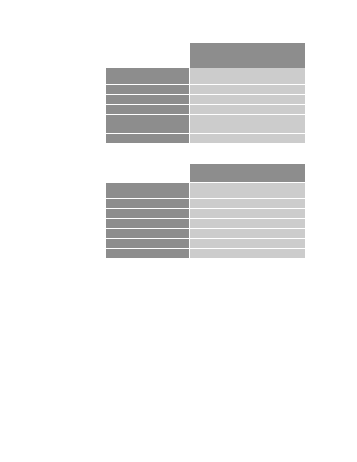
Environmental Specifications
(AR-01xx, AR-02xx, AR-04xx,
AR-08xx, AR-20xE, and AR-30xE)
Operating Temperature,
Maximum
Ambient Air 45°C (113°F)
Minimum 0°C (32°F)
Storage Temperature –40°C to 85°C (–40°F to 185°F)
Humidity 0 to 95%, non-condensing
Shock 15g, 11 ms half-sine
Vibration 10 to 2000 Hz at 2g
Pollution Degree 2 (per IEC 61010)
Installation Category 2 (per IEC 61010)
Table 4 Environmental Specifications, AR-01xx through AR-08xx, AR-20xE and AR-30xE
Operating Temperature,
Maximum
Environmental Specifications
(AR-13xx)
Ambient Air 40°C (104°F)
Minimum 0°C (32°F)
Storage Temperature –40°C to 85°C (–40°F to 185°F)
Humidity 0 to 95%, non-condensing
Shock 15g, 11 ms half-sine
Vibration 10 to 2000 Hz at 2g
Pollution Degree 2 (per IEC 61010)
Installation Category 2 (per IEC 61010)
Table 5 Environmental Specifications, AR-13xx
Cabinet Cooling
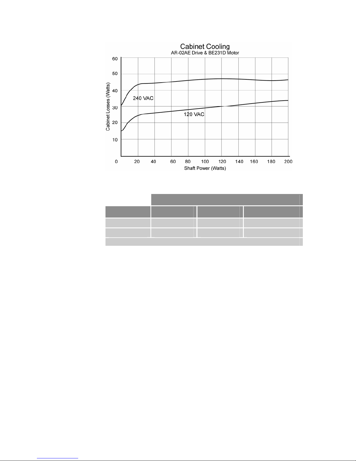
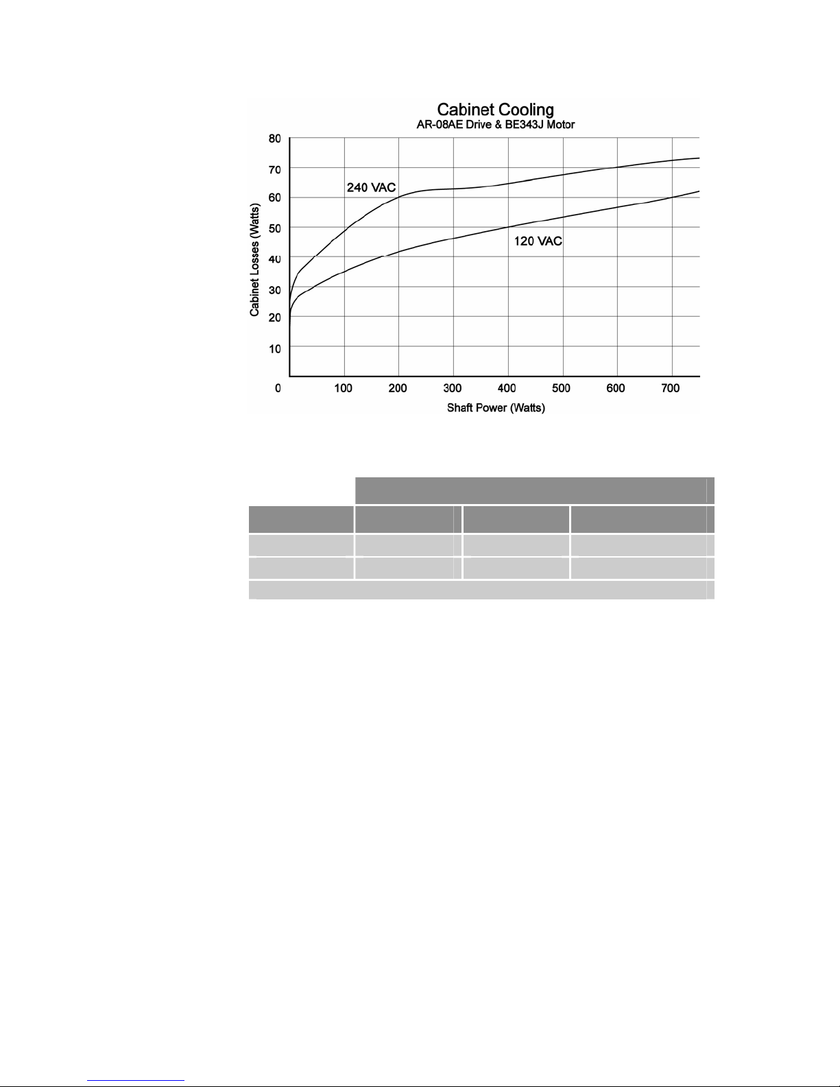
For cabinet cooling calculations, use Table 6 and Table 7 to determine the
power dissipation per drive.
AR-02xx
The power dissipation in Table 6 for the AR-02xx has been measured using
the Parker BE231D motor.
Chapter 2 Mechanical Installation 23
Page 24
Parker Hannifin
Figure 1 Cabinet Losses for AR-02xx when connected to a Parker BE231D motor
Shaft Power
Voltage 0W* 20W 200W
120 VAC 15W 25W 34W
240 VAC 32W 44W 47W
* Drive enabled, zero torque.
Table 6 AR-02xx Power Dissipation
AR-08xx
The power dissipation in Table 7 for the AR-08xx has been measured using
the Parker BE343J motor.
24 Aries User Guide
Page 25
Parker Hannifin
Figure 2 Cabinet losses for AR-08xx when connected to a Parker BE343J motor
Shaft Power
Voltage 0W* 200W 700W
120 VAC 13W 42W 60W
240 VAC 24W 60W 73W
* Drive enabled, zero torque.
Table 7 AR-08xx Power Dissipation
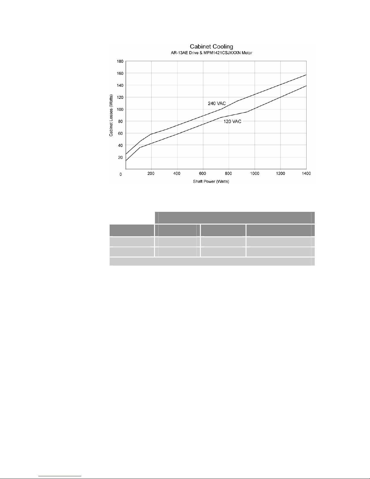
AR-13xx
The power dissipation in Table 8 for the AR-13xx has been measured using
the Parker MPM1421CSJXXXN motor.
Chapter 2 Mechanical Installation 25
Page 26
Parker Hannifin
Figure 3 Cabinet losses for AR-13xx when connected to a Parker MPM1421CSJ motor
Shaft Power
Voltage 0W* 700W 1300W
120 VAC 14W 82W 130W
240 VAC 25W 95W 146W
* Drive enabled, zero torque.
Table 8 AR-13xx Power Dissipation
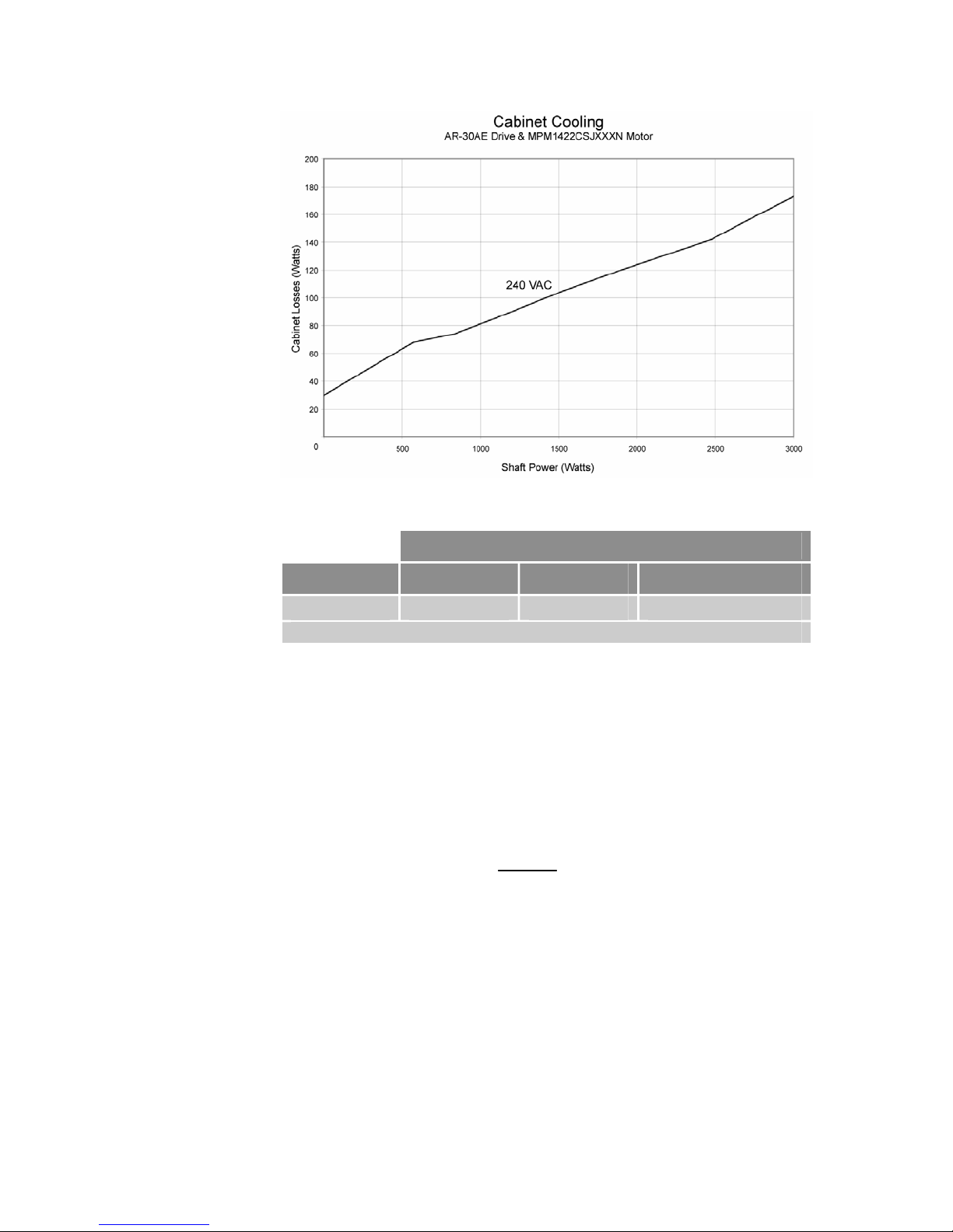
AR-30xE
The power dissipation in Table 9 for the AR-30xE has been measured using
the Parker MPM1422CSJXXXN motor.
26 Aries User Guide
Page 27
Parker Hannifin
Figure 4 Cabinet losses for AR-30xE when connected to a Parker MPM1422CSJ motor
Shaft Power
Voltage 0W* 1500W 3000W
240 VAC 35W 103W 172W
* Drive enabled, zero torque.
Table 9 AR-30xE Power Dissipation
Cabinet Cooling Calculations
Use the motor’s speed torque curve to determine the torque when the motor
is at running speed for your application. If the torque is not known, use the
“knee” (where the peak-torque curve intersects the continuous-torque curve)
of the graphed motion—this assumes the worst-case scenario for continuous
motion.
P
P −∗= 1
LOSS
= power dissipated to cabinet (Watts)
P
LOSS
P
E
E
= shaft power of the motor (Watts)
MOTOR
= efficiency of motor (Percent), approximately 0.85
MOTOR
= efficiency of Aries drive (Percent), approximately 0.90
DRIVE
MOTOR
E
MOTOR
()
E
DRIVE
Chapter 2 Mechanical Installation 27
Page 28
Parker Hannifin
Dimensions
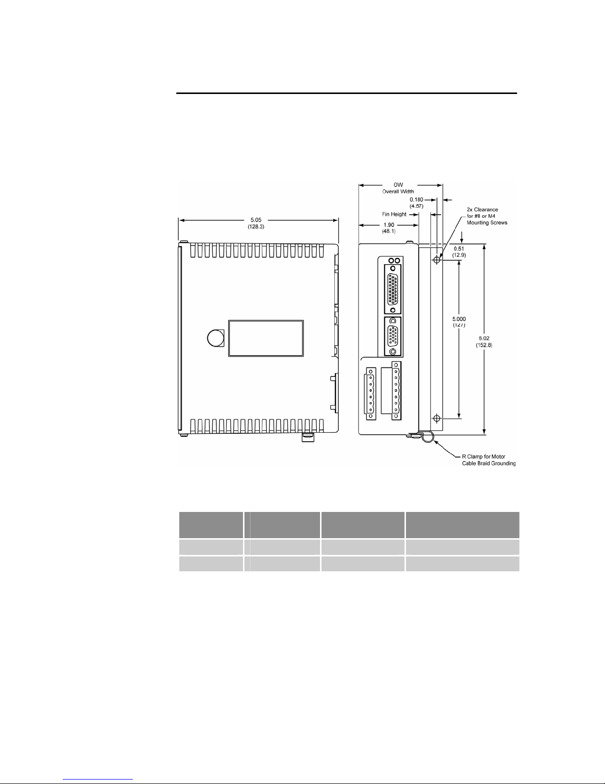
There are three basic housing sizes for the Aries drives. However, the height
of the heatsink fins varies with each model, except for the AR-20xE and
AR-30xE whose dimensions are identical. This section contains the
dimensions for all Aries models.
Drive Dimensions—AR-01xx & AR-02xx
28 Aries User Guide
Figure 5 Drive mounting for the AR-01xx & AR-02xx
Drive
Fin Height—
in (mm)
Outside Width
(OW)—in (mm)
Overall Depth
with Cables—in (mm)
AR-01xx 0.01 (0.25) 2.29 (58.2) 7.60 (193.0)
AR-02xx 0.375 (9.5) 2.65 (67.3) 7.60 (193.0)
Table 10 AR-01xx and AR-02xx Drive Dimensions
Page 29
Parker Hannifin
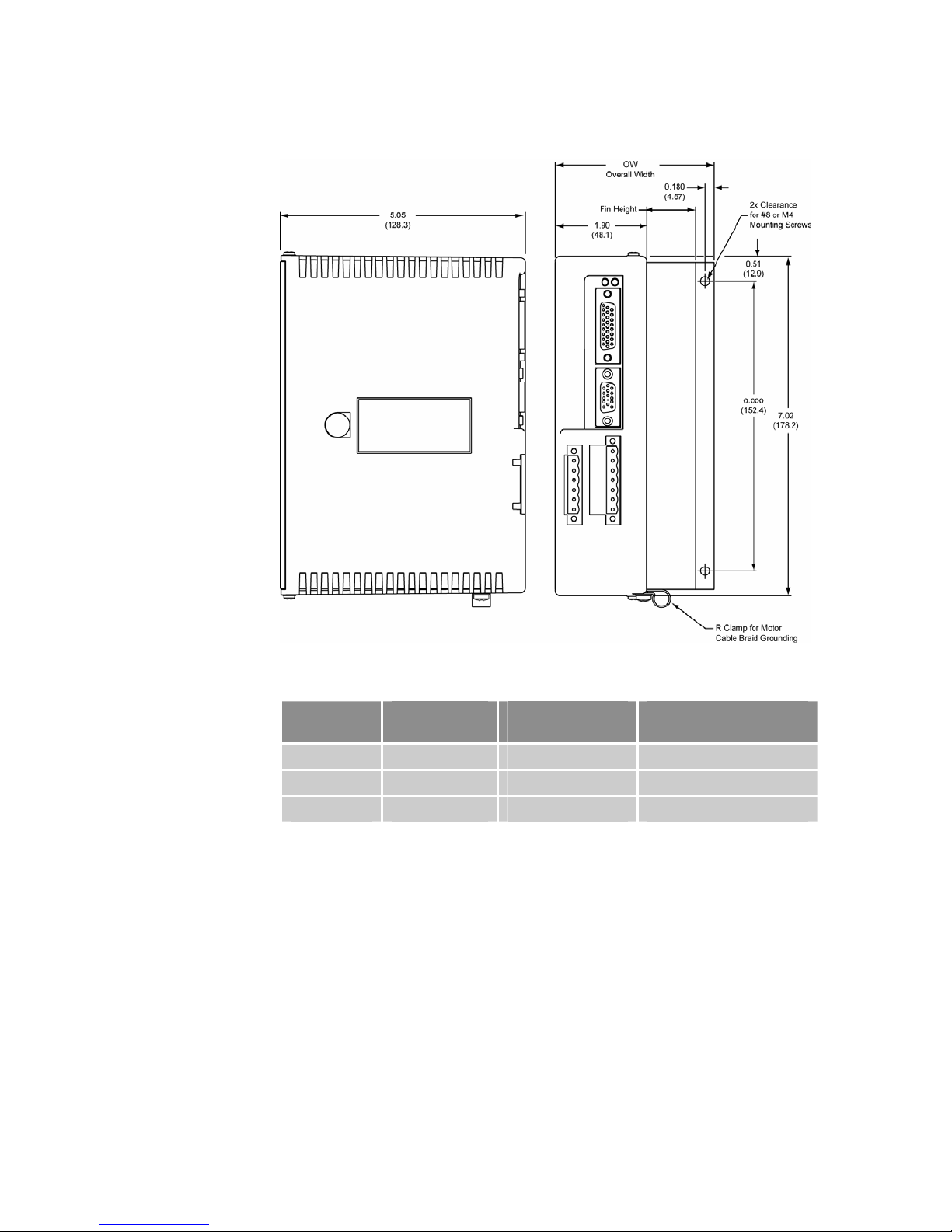
Drive Dimensions—AR-04xx, AR-08xx, & AR-13xx
Figure 6 Drive mounting for the AR-04xx, AR-08xx, and AR-13xx
Drive
Fin Height—
in (mm)
Overall Width
(OW)—in (mm)
Overall Depth
with Cables—in (mm)
AR-04xx 0.625 (15.9) 2.90 (73.7) 7.60 (193.0)
AR-08xx 1.00 (25.4) 3.28 (83.3) 7.60 (193.0)
AR-13xx 2.00 (50.8) 4.28 (108.7) 7.60 (193.0)
Table 11 AR-01xx , AR-02xx, & AR-13xx Drive Dimensions
Chapter 2 Mechanical Installation 29
Page 30
Parker Hannifin
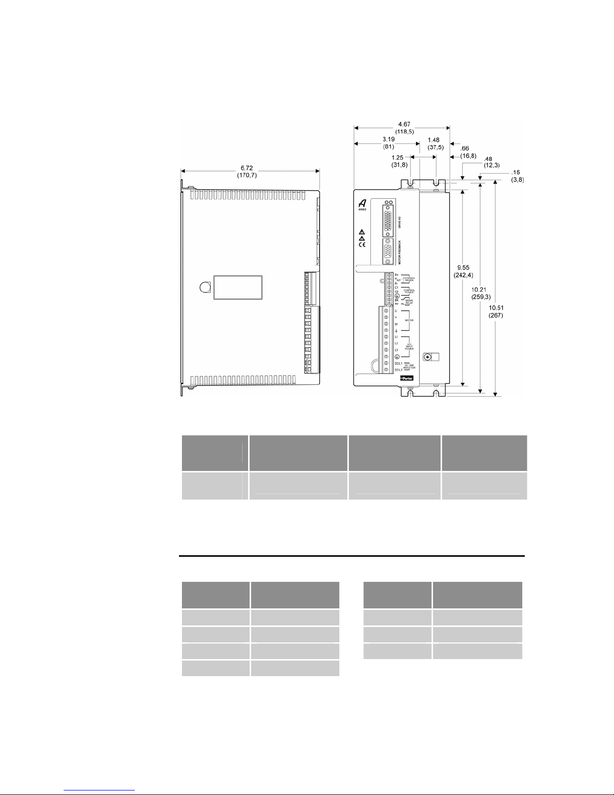
Drive Dimensions—AR-20xE & AR-30xE
Figure 7 Drive mounting for the AR-20xE and AR-30xE
Drive
AR-20xE &
AR-30xE
Table 12 AR-20xE and AR-30xE Drive Dimensions
Fin Height—
in (mm)
1.48 (37.5) 4.67 (118.5) 9.27 (235.5)
Overall Width
(OW)—in (mm)
Overall Depth
with Cables—in
Weight
Use Table 13 to determine the weight of your drive.
Drive
Weight
pounds (kg)
Drive
AR-01xx 1.68 (0.76) AR-13xx 3.60 (1.63)
AR-02xx 1.90 (0.86) AR-20xE 7.35 (3.33)
AR-04xx 2.54 (1.15) AR-30xE 7.40 (3.36)
AR-08xx 2.82 (1.28)
Weight
pounds (kg)
(mm)
Table 13 Drive Weight
30 Aries User Guide
Page 31
Parker Hannifin
Mounting Guidelines
The Aries drive is a vented product. To prevent material spilling into the
drive, mount it under an overhang or in a suitable enclosure.
Aries products are made available under “Restricted Distribution” for use in
the “Second Environment” as described in EN 61800-3 1996, page 9.
Cable Routing
Route high power cables (motor and mains) at right angles to low power
cables (communications and inputs/outputs). Never route high and low power
cables parallel to each other.
Panel Mounting
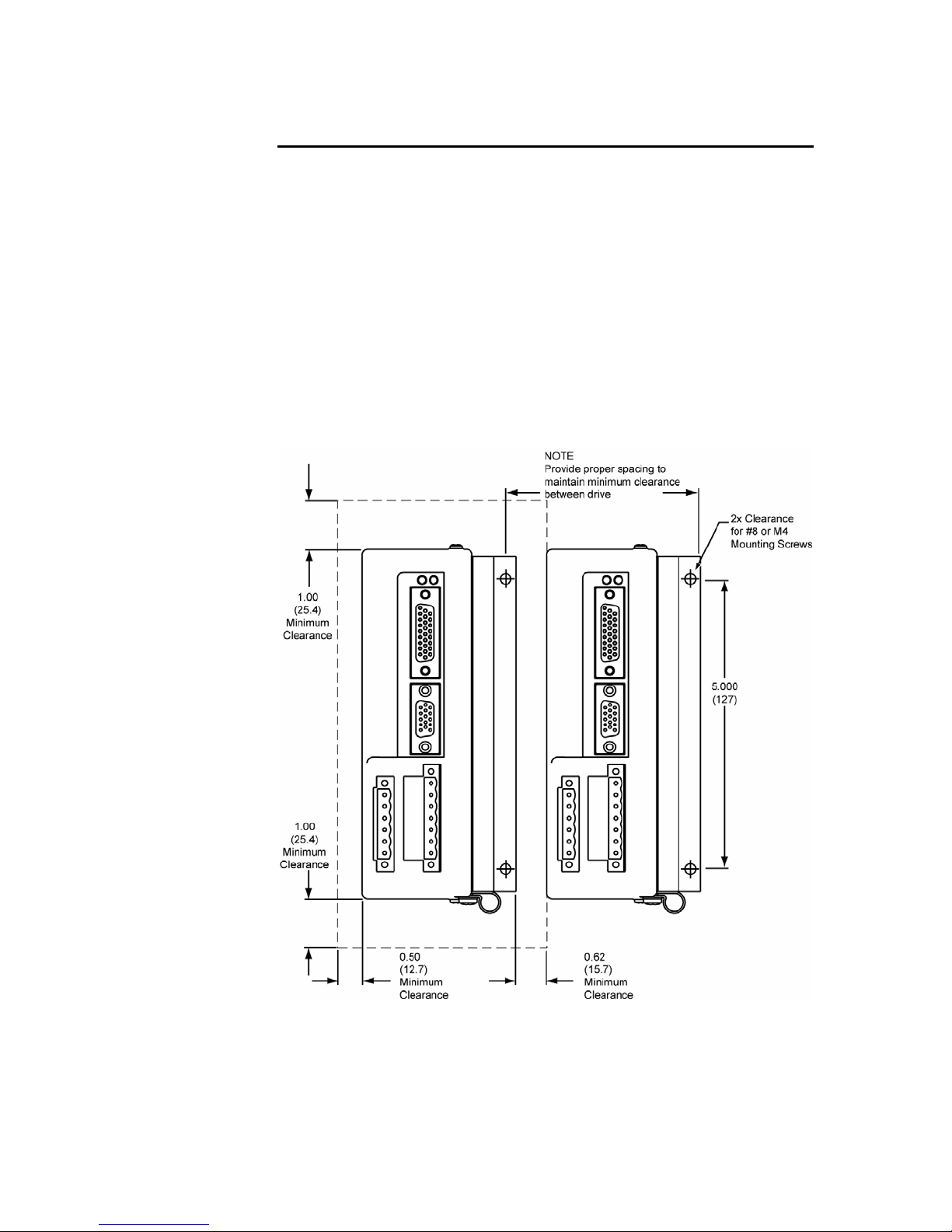
The mounting clearance requirements are the same for all models of the
Aries Drive. They are shown in Figure 8.
Figure 8 Panel Layout Dimensions for Aries Drives
Chapter 2 Mechanical Installation 31
Page 32
Chapter 3 Electrical Installation
CHAPTER THREE
Electrical
Installation
Installation Safety Requirements............................................................... 33
System Installation Overview..................................................................... 34
Power Suppl
Multiple Drive Ins
Brake Relay (Optional
Regeneration Protection
LEDs⎯Drive Status
Connector Desc
Installation Test.......................................................................................... 72
IN THIS CHAPTER
y............................................................................................. 35
tallations......................................................................... 48
) ..............................................................................50
............................................................................54
Indicators ..................................................................56
riptions .............................................................................57
Page 33

Parker Hannifin
Installation Safety Requirements
Aries drives meet the requirements of both the European LVD (Low Voltage
Directive) and EMC (Electromagnetic Compliance) directives when installed
according to the instructions given within “Appendix C Regulatory
Compli
As a rule, it is recommended that you install the drive in an enclosure to
protect it from atmospheric contaminants and to prevent operator access
while power is applied. Metal equipment cabinets are ideally suited for
housing the equipment because they provide operator protection, EMC
screening, and can be fitted with interlocks arranged to remove all hazardous
motor and drive power when the cabinet door is opened.
Do not arrange the interlocks to open circuit the motor phase connections
while the system is still powered as this could damage the drive.
Precautions
During installation, take the normal precautions against damage caused by
electrostatic discharges.
ance–UL and CE”.
• Wear earth wrist straps.
• Include a mains power switch or circuit breaker within easy reach of
the machine operator. Label, clearly, the switch or breaker as the
disconnecting device.
Auto-Configuration for Encoders
The Aries drive recognizes “smart encoders” attached to Parker motors. You
can apply power to the drive, and the drive reads all necessary motor
parameters from the motor. The drive and motor are then ready to use.
If a drive is swapped out for any reason, you can insert a replacement—the
replacement drive automatically reads the motor parameters.
Several drive related parameters may need additional configuration: CMDDIR,
DCMDZ, and ADDR.
Chapter 3 Electrical Installation 33
Page 34
Parker Hannifin
System Installation Overview
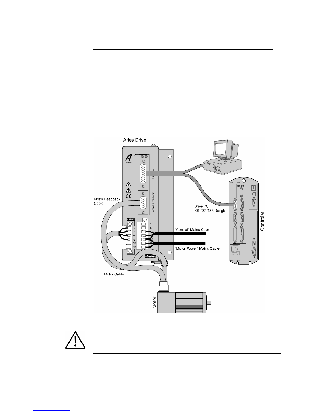
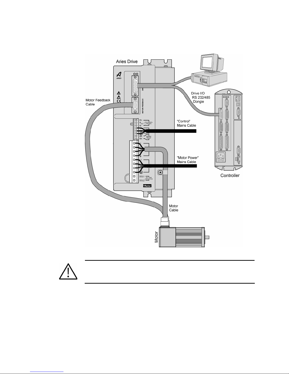
The figures in this section illustrate the components necessary for electrical
installation and configuration of the Aries drive. Figure 9 represents the
installatio
installatio
the other five models.
The illustration shows the use of the Aries dongle (part number 71-021609-
01), which connects the Aries drive to both a controller and a personal
computer (PC). The dongle is for setup purposes only. Do not use the dongle
for permanent installation.
AR-01xx, AR-02xx, AR-04xx, AR-08xx, & AR-13xx
Installation
n of models AR-01xx through AR-13xx. Figure 11 shows the
n of models AR-20xE and AR-30xE, whose connectors differ from
Figure 9 Overview of System Installation for AR-01xx to AR-13xx
Warning — This product has been developed for industrial environments. Due
to exposed high voltage terminals, this product must not be accessible to users
while under normal operation.
34 Aries User Guide
Page 35
Parker Hannifin
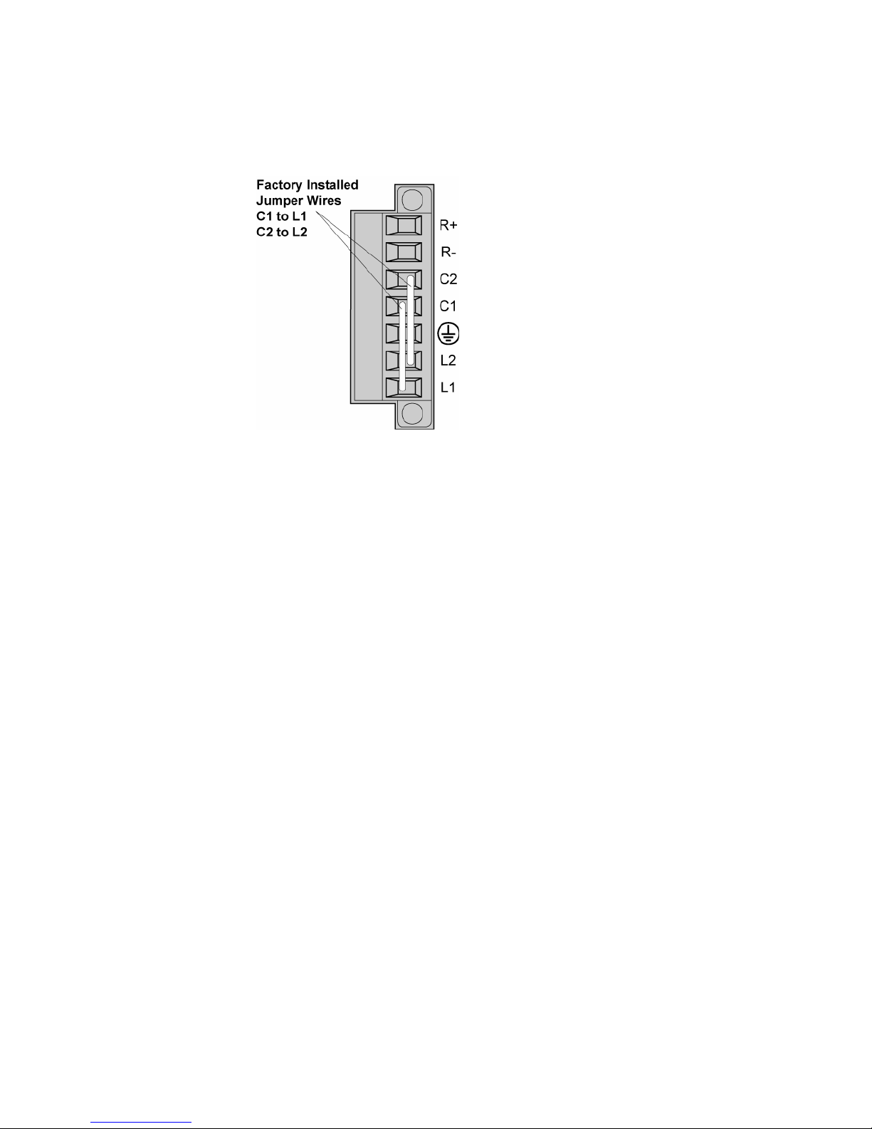
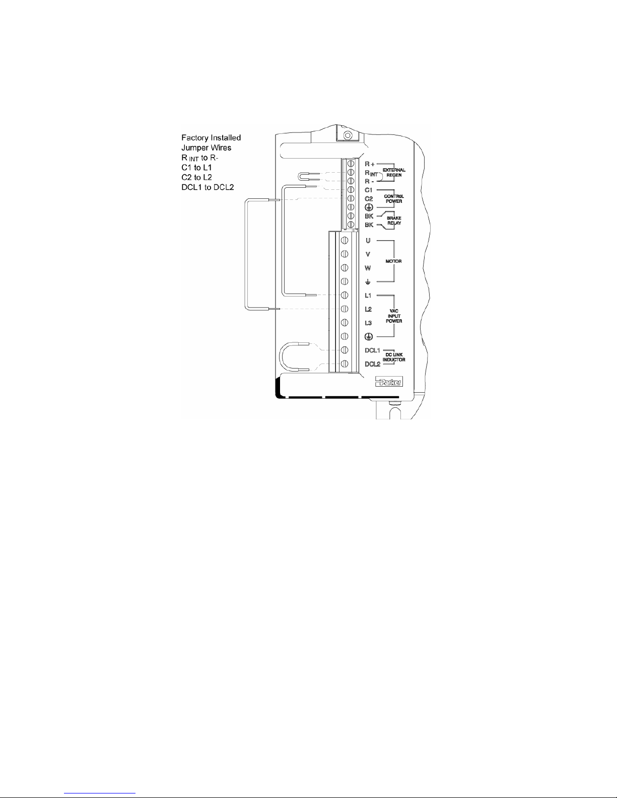
To operate the Aries drive with separate control and motor AC input, remove
the factory installed external jumpers. With the jumpers installed, apply
power to the motor power mains only. Figure 10 shows the location of the
factory in
stalled jumpers.
Figure 10 AR-01xx to AR-13xx Factory Installed Jumpers
Chapter 3 Electrical Installation 35
Page 36
Parker Hannifin
AR-20xE and AR-30xE Installation
Figure 11 Overview of System Installation for AR-20xE & AR-30xE
Warning — This product has been developed for industrial environments. Due to
exposed high voltage terminals, this product must not be accessible to users
while under normal operation.
36 Aries User Guide
Page 37
Parker Hannifin
To operate the Aries drive with separate control and motor AC input, remove
the factory installed external jumpers. With the jumpers installed, apply
power to the motor power mains only. Figure 12 shows the location of the
factory in
stalled jumpers.
Figure 12 AR-20xE to AR-30xE Factory Installed Jumpers
Connector Locations
All Aries drive models have identical DRIVE I/O and Motor Feedback
connectors. However, the connectors for motor and control power, on the
AR-20xE and AR-30xE differ from the other models due to their higher power
capacity. The two power connectors on models AR-01xx through AR-13xx
are removable. The two power connectors on Models AR-20xE and AR-30xE
are non-removable. Descriptions of individual connectors and their
specifications follow in this chapter. See “Connector Descriptions,” and in
“Appendix A Additional Specifications.”
Figure 13 shows the names and location of the connectors on Aries drive
s AR-01xx through AR-13xx. Figure 14 shows them on the higher-
model
power mo
dels AR-20xE and AR-30xE.
Chapter 3 Electrical Installation 37
Page 38

Parker Hannifin
Figure 13 Connectors on Aries Models AR-01xx to AR-13xx
Figure 14 Connectors on Aries Models AR-20xE & AR-30xE
38 Aries User Guide
Page 39
Parker Hannifin
Power Supply
Input Power
The mains motor power supply and control power supply for the Aries Drive
must meet the following requirements.
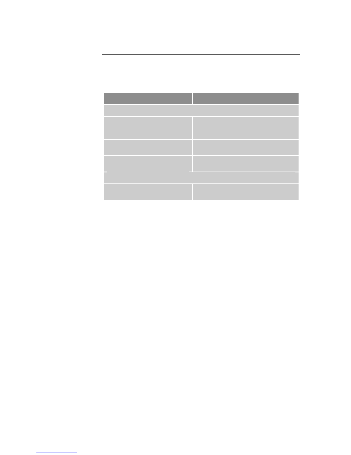
Model Requirements
Motor Input Power
AR-01xx, AR-02xx, AR-04xx,
AR-08xx, AR-13xx
(L1, L2)
AR-20xE
(L1, L2, L3)
AR-30xE
(L1, L2, L3)
Control Input Power
All models
(C1, C2)
120/240 VAC, 50/60 Hz, single phase
240 VAC, 50/60 Hz, single phase or
three phase
240 VAC, 50/60 Hz, three phase only
120/240 VAC, single phase
Figure 15 Input Power Requirements
Mains/Input Power Connector
AR-01xx, AR-02xx,AR-04xx, AR-08xx, AR-13xx
Connector Type.......................................Removable screw terminal
Terminals ........................................7
Pitch ................... 0.200 in (5.08 mm)
Wire Range....................12-26 AWG
.......................................14-27 SWG
................................(0.12-3.30 mm
Wire Strip length .. 0.31 in (7.87 mm)
Torque....7.0 in–lbs nom. (0.79 N-m)
AR-20xE, AR-30xE
Connector Type.......................................Non-Removable screw terminal
Terminals ......................................10
Pitch ........................ 0.315 in (8 mm)
Wire Range....................10-22 AWG
.......................................12-23 SWG
....................................(0.5-4.0 mm
Wire Strip length .... 0.25 in (6.5 mm)
Torque....7.0 in–lbs nom. (0.79 N-m)
2
)
2
)
Chapter 3 Electrical Installation 39
Page 40
Parker Hannifin
AC Power Supply Connection
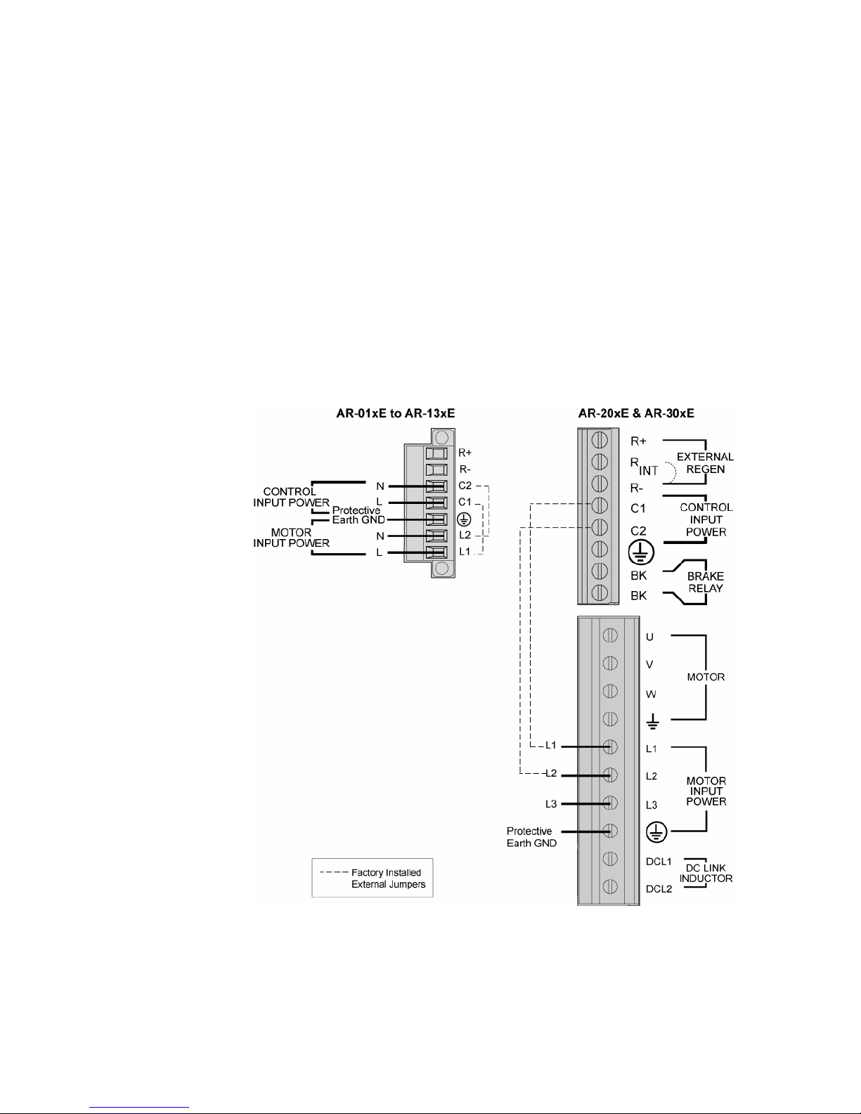
Figure 16 on page 34 shows how to connect the external 120/240 VAC motor
power source and control power sources to the drive.
• The AR-20xE can accept single-phase or three-phase 240V motor
power. For single-phase connections, make no connection to
terminal labeled L3.
• The AR-30xE can only accept three-phase 240V motor power.
Use the terminal connector that is supplied with the drive. For the Protective
Earth ground, make the connection directly by means of a low-impedance
path less than or equal to 0.1 ohm (no fuses, etc.). Under normal operation,
no current should flow through the Protective Earth connection.
If desired, you can jumper two phases of the motor input power to the control
input power for a single AC power connection. Jumpers are installed at the
factory for this purpose. Remove the jumpers to apply separate control and
motor mains power.
Figure 16 Motor and Control Mains Power Supply Connection
Note: See warnings on next page.
40 Aries User Guide
Page 41
Parker Hannifin
Warning — You must connect the drive’s protective conductor terminal, marked
with the earth symbol
, to a reliable system Protective Earth.
Warning — The drive’s connector strip terminals have hazardous voltages when
power is applied to the drive, and up to several minutes after power is removed.
Lower voltages may still be present for several minutes after power is removed.
During normal operation, these high voltage terminals must not be accessible to
the user.
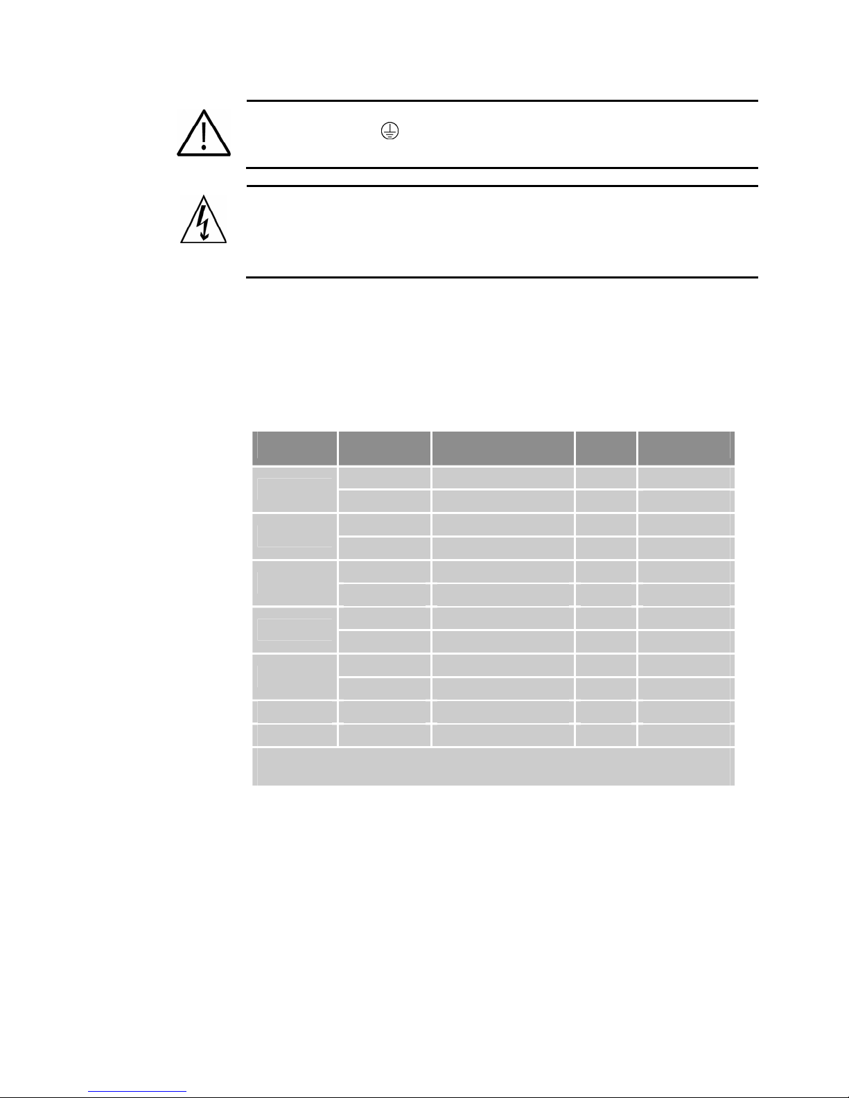
Motor Power Fuse Information
Aries drives have no user-serviceable internal fuses. For safety, you must
provide a fuse in each of the AC Mains Motor power input lines. To
determine the proper fuse type and size for your application, see Table 14.
r fuse recommendations for Control-power input lines, see “Control Power
(Fo
Supply” on p
Drive AC Voltage Fuse Style Rating Fuse Type
age 46.)
AR-01xx
120 VAC 125 VAC Time Delay 10A RK5 or better
240 VAC 250 VAC Time Delay 10A RK5 or better
120 VAC 125 VAC Time Delay 10A RK5 or better
AR-02xx
240 VAC 250 VAC Time Delay 10A RK5 or better
120 VAC 125 VAC Time Delay 20A RK5 or better
AR-04xx
240 VAC 250 VAC Time Delay 20A RK5 or better
120 VAC 125 VAC Time Delay 20A RK5 or better
AR-08xx
240 VAC 250 VAC Time Delay 20A RK5 or better
120 VAC 125 VAC Time Delay 30A RK5 or better
AR-13xx
240 VAC 250 VAC Time Delay 30A RK5 or better
AR-20xE* 240 VAC 250 VAC Time Delay 40A RK5 or better
AR-30xE* 240 VAC 250 VAC Time Delay 40A RK5 or better
* The 40A fuse is recommended regardless of whether the input power is
single-phase or 3-phase.
Table 14 Motor Power Fuse Information
Chapter 3 Electrical Installation 41
Page 42
Parker Hannifin
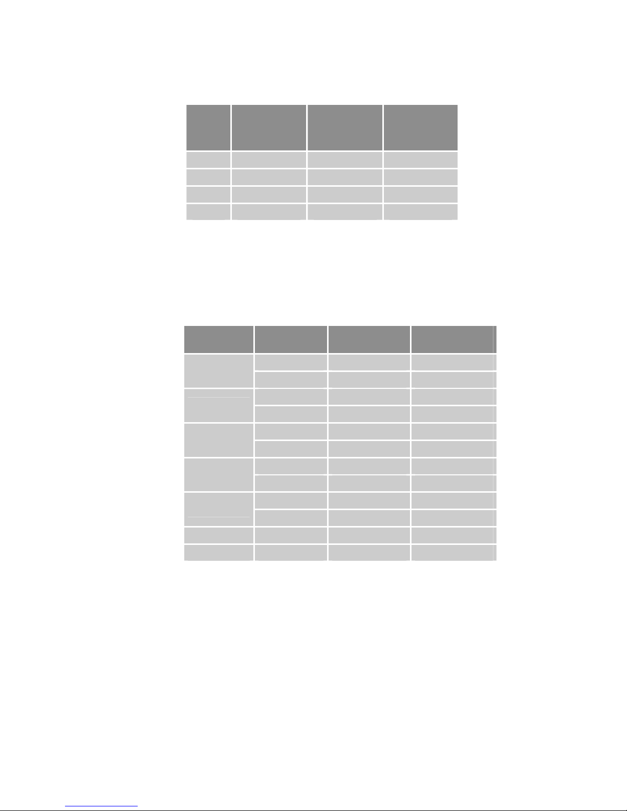
Table 15 lists part numbers (at time of publication) for suitable fuses from
several manufacturers. These fuses are type RK5 (time delay fuses).
Ferraz
Amps Bussmann
Shawmut
(formerly
Gould)
Littelfuse
10 FRN-R-10 TR10R FLNR10
20 FRN-R-20 TR20R FLNR20
30 FRN-R-30 TR30R FLNR30
40 FRN-R-40 TR40R FLNR40
Table 15 Fuse Part Numbers
Drive Inrush Current
The drive inrush current is limited by an internal thermistor that changes
value with the ambient temperature. Drive inrush current is therefore
dependent upon the temperature of the surrounding environment (T
determine the drive inrush current for your drive, see Table 16.
amb
). To
Drive Type
AC Voltage Drive Inrush
(25°C T
amb
)
120 VAC 34A 73A
AR-01xx
240 VAC 68A 146A
120 VAC 34A 73A
AR-02xx
240 VAC 68A 146A
120 VAC 17A 36A
AR-04xx
240 VAC 34A 73A
120 VAC 17A 36A
AR-08xx
240 VAC 34A 73A
120 VAC 17A 36A
AR13xE
240 VAC 34A 73A
AR-20xE 240 VAC 68A 155A
AR-30xE 240 VAC 68A 155A
Table 16 Drive Motor Power Inrush Current
Drive Inrush
(50°C T
amb
)
42 Aries User Guide
Page 43
Parker Hannifin
Output Power
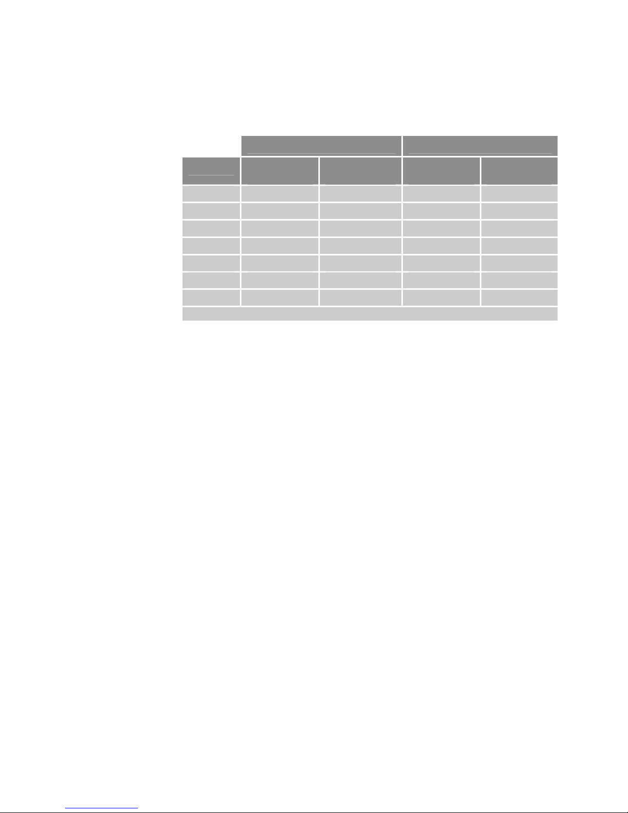
Table 17 contains the continuous and peak output power ratings for all Aries
drive models.
Drive Current (Amps,
Continuous Output Peak Output
RMS)
Shaft Power*
(Watts, max)
Current
(Amps, RMS)
Shaft Power
(Watts, max)
AR-01xx 1.0 100 3.0 300
AR-02xx 1.75 200 5.25 600
AR-04xx 3.0 400 9.0 1200
AR-08xx 4.5 750 13.5 2250
AR-13xx 6.3 1300 14.1 3900
AR-20xE 10 2000 30 6000
AR-30xE 16 3000 48 9000
* Maximum shaft power rating at 240 VAC
Table 17 Output Power-Continuous and Peak
Motor Connector
AR-01xx, AR-02xx, AR-04xx,
AR-08xx, AR-13xx
Connector Type.......................................Removable screw terminal
Terminals ........................................6
Pitch ................... 0.200 in (5.08 mm)
Wire range .....................12-26 AWG
.......................................14-27 SWG
................................(0.12-3.30 mm
Wire strip length...... 0.310 in (8 mm)
Torque....7.0 in–lbs nom. (0.79 N-m)
2
)
AR-20xE, AR-30xE
Connector Type.......................................Non-Removable screw terminal
Terminals ......................................10
Pitch ........................ 0.315 in (8 mm)
Wire range .....................10-22 AWG
.......................................12-23 SWG
....................................(0.5-4.0 mm
Wire strip length..... 0.25 in (6.5 mm)
Torque....7.0 in–lbs nom. (0.79 N-m)
Chapter 3 Electrical Installation 43
2
)
Page 44
Parker Hannifin
Output Power Connection
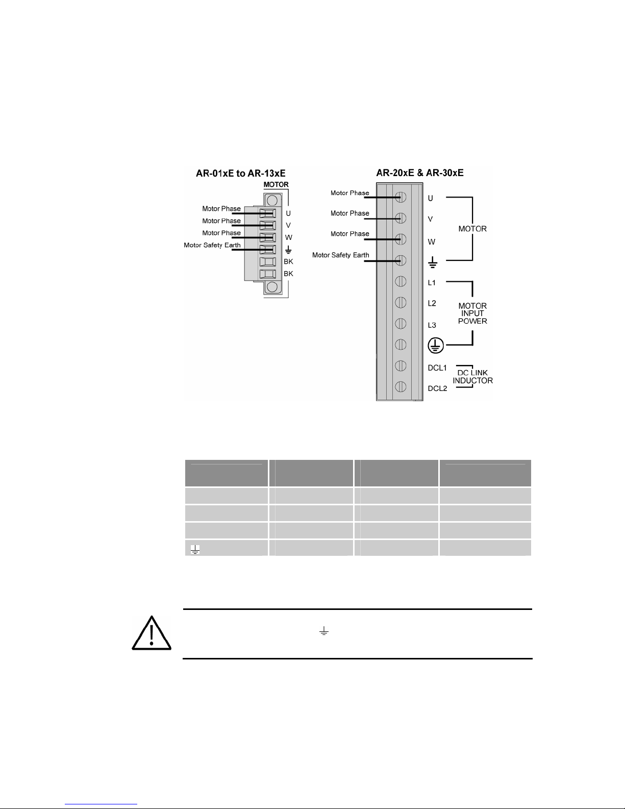
Figure 17 shows how to connect the motor cable to the drive. Use the screw
terminal connector that is installed in the drive. Current Parker motor cables
are marked with white numbers to indicate the phases. Connect Motor Phase
1 Æ U, 2 Æ V, and 3 Æ W, and Motor Safety Earth to the Protective Earth
ground connector.
Figure 17 Output Power Connection
Table 18 contains information for making connections with Parker Hannifin
motors.
Phase
Hi-Flex/ PS/
Gemini
Legacy Parker
Hannifin
Legacy MaxPlus
U 1 Red/Yellow Red
V 2 White/Yellow Black
W 3 Black/Yellow Blue
Table 18 Wiring to Motors
Green/Yellow Green/Yellow Green
Note: On models AR-20xE and AR-30xE, the Motor Brake Relay is on a
separate connector. See Figure 22 on page 50.
Warning — You must connect the Motor Safety Earth conductor terminal,
marked with the earth symbol
(green/yellow).
, to the motor cable’s motor-safety-earth wire
e: See additional warning on next page.
Not
44 Aries User Guide
Page 45
Parker Hannifin
Warning — The drive’s connector strip terminals have hazardous voltages
when power is applied to the drive, and up to several minutes after power is
removed. Lower voltages may still be present for several minutes after power
is removed. During normal operation, these high voltage terminals must not
be accessible to the user.
External DC Link Inductor (Optional)
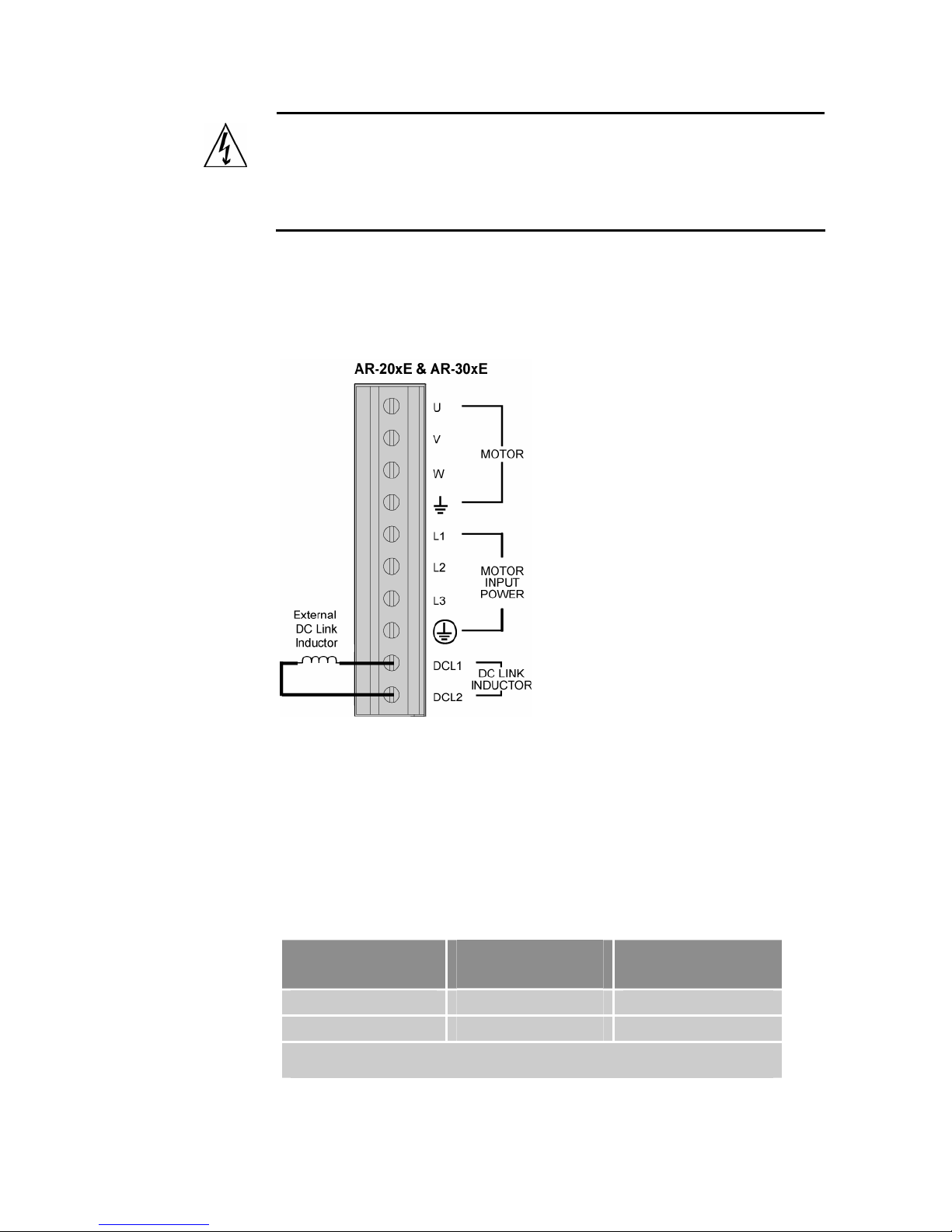
The Aries AR-20xE and AR-30xE drives have two extra terminals that allow
an external DC link inductor to be added if required. To add the DC link
inductor, remove the factory installed shorting link, and connect the inductor
as shown in Figure 18.
Figure 18 External DC Link Inductor Connection
If a drive is supplied from a low-impedance source (for example, a
transformer that has a kVA rating more than 10 times the drive), the input line
currents to the drive can be non-sinusoidal. They may have a peak that is
two to three times the rms value, compared to 1.4 times for a sinusoidal
waveform. This results in higher currents being drawn from the line at rated
power and harmonics that might interfere with other equipment. The addition
of a DC link inductor reduces the severity of these problems.
Table 19 provides compatible DC link inductors for the Aries AR-20xE and
AR-30xE.
Drive Type
Recommended
Inductance
DC Current Rating
AR-20xE 1.0 to 3.0 mH 10A
AR-30xE 0.75 to 2.0 mH 15A
Note: Where within the recommended range, the larger inductance gives a better
shape to the input current waveform, but at the expense of larger physical size.
Table 19 AR-20xE & AR-30xE DC Link Inductors
Chapter 3 Electrical Installation 45
Page 46

Parker Hannifin
Control Power Supply
With Mains power applied to the Control power terminals C1 and C2, the
drive’s internal control board remains powered when the primary motor AC
power source (L1, L2 (L3)) is disconnected. When operated in this
configuration, the Control power input performs a “keep-alive” function. The
keep-alive circuit maintains several important functions, including
communications, diagnostics, position feedback, and other logic functions,
while removing power from the motor output connection. (See the following
section, Fuse Information, for a complete list of Control
Remove the factory installed jumpers to use the product with separate
control and motor mains AC power input.
Fuse Information
Fuse Rating............................................. 1 Amp
Fuse Type ...............................................Class CC (Bussmann KTK-R-1 or
equivalent UL listed fuse)
Input Voltage Range ...............................120/240 VAC, 50/60 Hz
Input Current ...........................................0.2 Amps RMS
power functions.)
Control Power Functions......................... Communications
Diagnostics
Motor position feedback
Fault output in fault mode
Brake relay in brake mode
Reset input
Control Power Connector
AR-01xx, AR-02xx,
AR-04xx, AR-08xx, AR-13xx
Connector Type.......................................Removable screw terminal
Terminals ........................................7
Pitch ................... 0.200 in (5.08 mm)
Wire Range....................12-26 AWG
.......................................14-27 SWG
................................(0.12-3.30 mm
Wire Strip length .. 0.31 in (7.87 mm)
Torque....7.0 in–lbs nom. (0.79 N-m)
2
)
46 Aries User Guide
Page 47
Parker Hannifin
AR-20xE, AR-30xE
Connector Type.......................................Non-Removable screw terminal
Terminals ........................................8
Pitch ...................... 0.400 in (10 mm)
Wire Range....................12-28 AWG
.......................................14-29 SWG
................................(0.12-3.30 mm
Wire Strip length 0.250 in (6.35 mm)
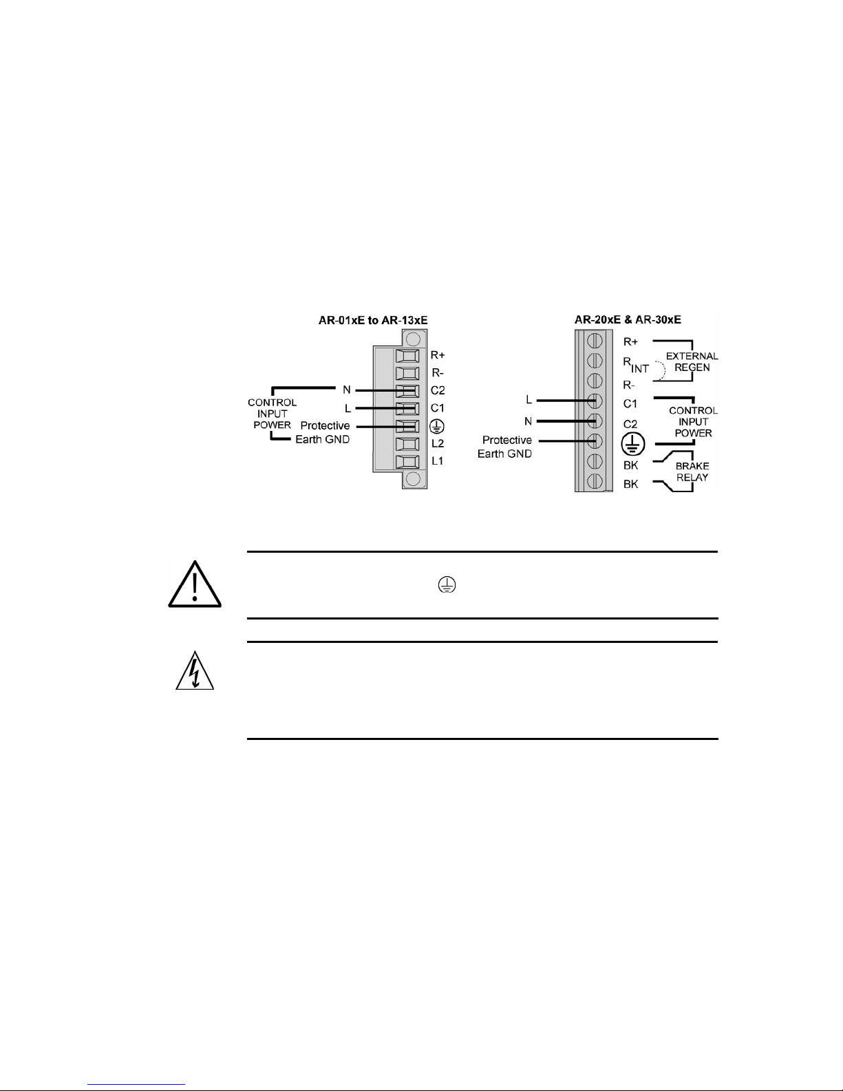
Control Power Connection
Figure 19 shows how to connect the Control power source to the drive. Use
the screw terminal connector that is supplied with the drive.
2
)
Figure 19 Mains Control Input Power
Warning — You must connect the drive’s protective conductor terminal,
marked with the earth symbol
Warning — The drive’s connector strip terminals have hazardous
voltages when power is applied to the drive, and up to several minutes
after power is removed. Lower voltages may still be present for several
minutes after power is removed. During normal operation, these high
voltage terminals must not be accessible to the user.
, to a reliable system Protective Earth.
Chapter 3 Electrical Installation 47
Page 48
Parker Hannifin
Multiple Drive Installations
In a typical cabinet installation, a single mains line connects to a terminal bus
inside the cabinet. Then from the terminal bus, make individual connections
for Mains and Control power to the corresponding
drive. Be sure to install fuses for each drive between the terminal bus and the
drive.
connector(s) on each
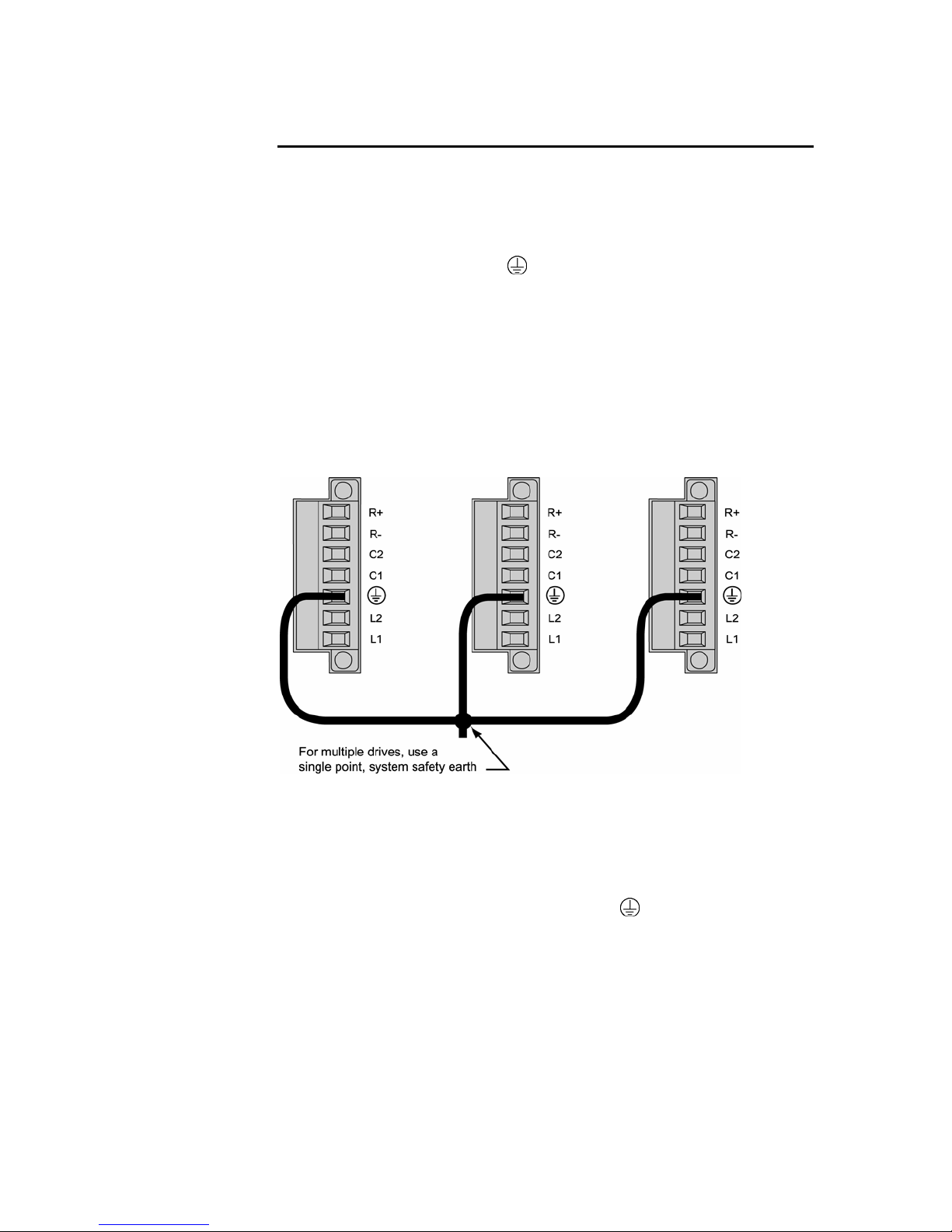
Tie each drive’s Protective Earth
safety earth location as shown in Figure 20 (for models AR-01xx through AR13xx) or Figure 21 (for models AR-20xE and AR-30xE). Under normal
operation, no
current should flow through the Protective Earth ground.
conductor terminal directly to the system
Safety Earth Connections
AR-01xx, AR-02xx, AR-04xx, AR-08xx, and AR-13xx
For multiple drive installations, Parker Hannifin recommends a single point or
“star” safety earth configuration. Figure 20 represents a typical star safety
earth conn
ection for Aries models AR-01xx through AR-13xx.
Figure 20 Multiple Drives AR-01xx to AR-13xx: Single Point Safety Earth
AR-20xE and AR-30xE
Figure 21 represents a typical star safety earth connection for Aries models
0xE and AR-30xE. Note that the AR-20xE and AR-30xE Motor/Power
AR-2
connector has two Earth ground terminals⎯one for the motor and one for
input power. Be sure to use the
48 Aries User Guide
VAC INPUT POWER terminal.
Page 49
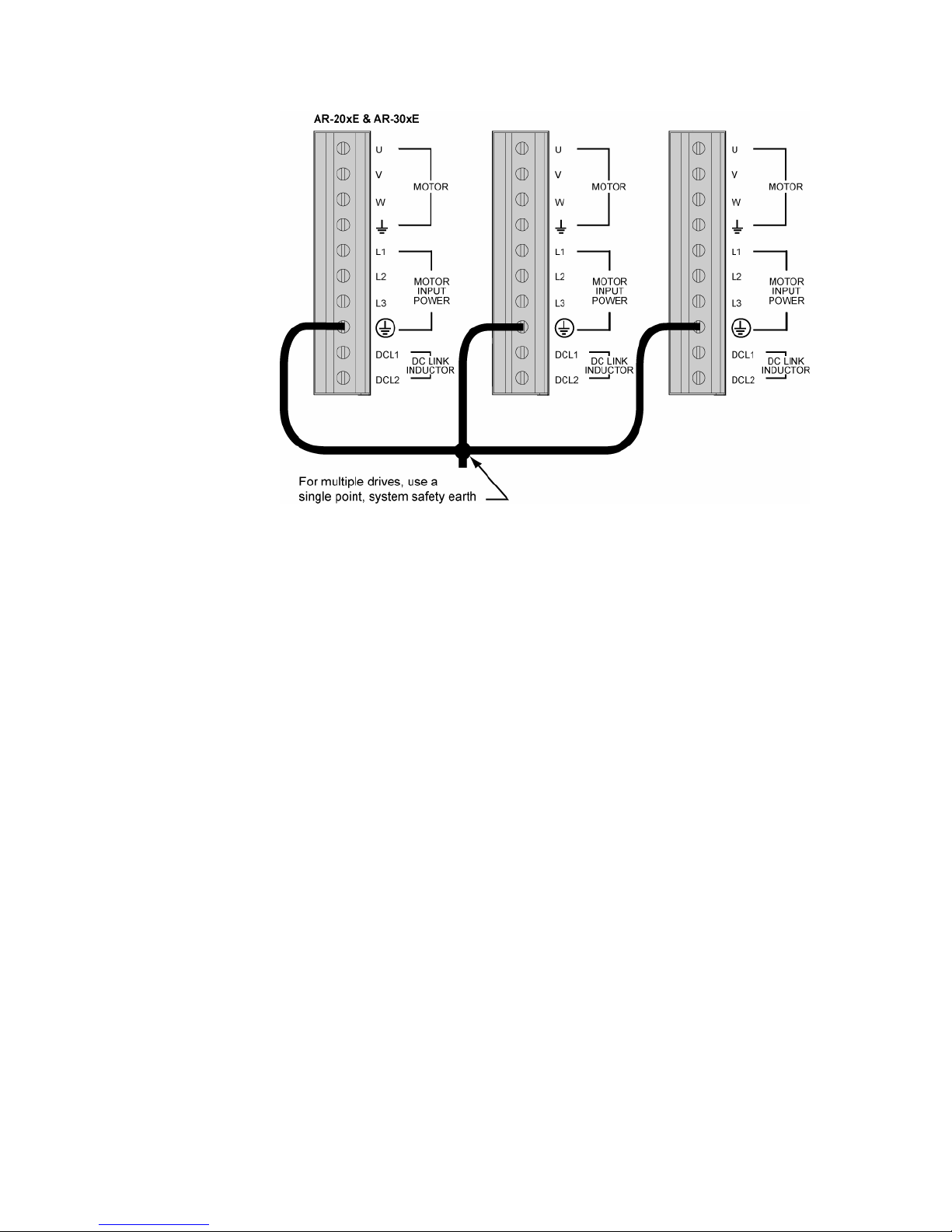
Parker Hannifin
Figure 21 Multiple Drives AR-20xE & AR-30xE: Single Point Safety Earth
Chapter 3 Electrical Installation 49
Page 50
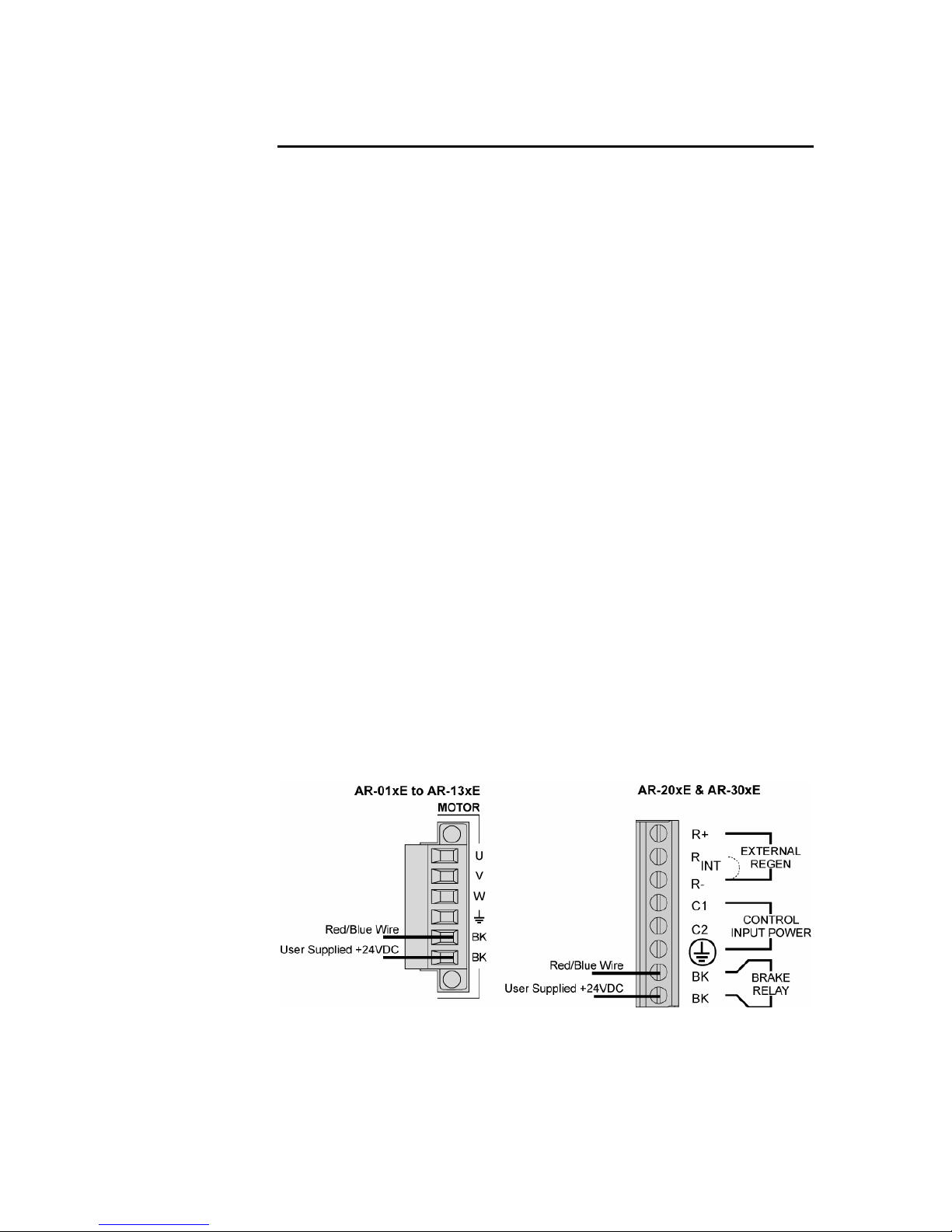
Parker Hannifin
Brake Relay (Optional)
[The Brake Relay connection provides a safety feature for your motion
control system, particularly for vertical applications. The drive acts as a
control switch for the motor brake (if a brake is present). When 24V is applied
from an outside power supply through the drive’s BK terminals, the motor
brake is disabled. When the power supply is interrupted, or the drive faults or
is disabled, the brake is enabled and stops shaft rotation. Connector and
wiring information follow in this section.
Brake Relay Connector
AR-01xx, AR-02xx, AR-04xx,
AR-08xx, AR-13xx
Connector Type.......................................Removable screw terminal
Terminals ........................................6
Pitch ................... 0.200 in (5.08 mm)
Wire range .....................12-26 AWG
.......................................14-27 SWG
................................(0.12-3.30 mm
Wire strip length...... 0.310 in (8 mm)
Torque....7.0 in–lbs nom. (0.79 N-m)
2
)
AR-20xE, AR-30xE
Connector Type.......................................Non-Removable screw terminal
Terminals ........................................8
Pitch ...................... 0.400 in (10 mm)
Wire Range....................12-28 AWG
.......................................14-29 SWG
................................(0.12-3.30 mm
Wire Strip length 0.250 in (6.35 mm)
Brake Relay Connection
On all models, this set of terminals is optically isolated from the drive’s
internal logic.
2
)
Figure 22 Typical Brake Relay Connection
Important warnings:
50 Aries User Guide
Page 51
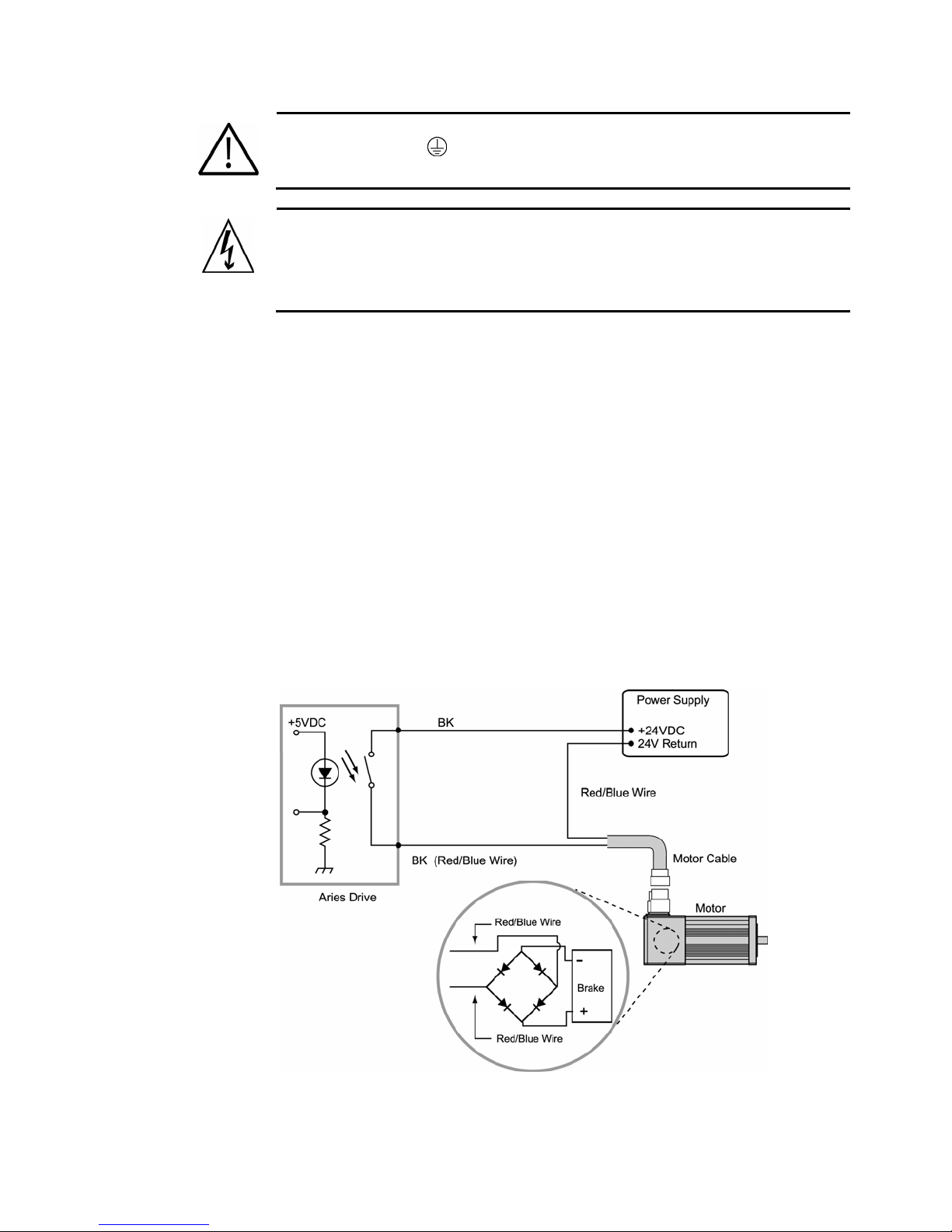
Parker Hannifin
Warning — You must connect the drive’s protective conductor terminal, marked
with the earth symbol
Warning — The drive’s connector strip terminals have hazardous voltages when
power is applied to the drive, and up to several minutes after power is removed.
Lower voltages may still be present for several minutes after power is removed.
During normal operation, these high voltage terminals must not be accessible to
the user.
, to a reliable system Protective Earth.
Motor with Full Wave Rectifiers
Some Parker brake motors (BE, SM, SE, NeoMetric, and J series motors,
serial numbers greater than 010904xxxxx) contain full wave rectifiers, so
connection polarity is not an issue during installation.
Connecting the Brake Relay
1. Connect one red/blue brake wire (Parker Motor cable or equivalent) to
the BK terminal of the Motor connector on Aries models AR-01xx to
AR-13xx, or the Control connector on models AR-20xE and AR-30xE.
2. Connect the second red/blue brake wire (Parker Motor cable or
equivalent) to the 24V return on your power supply.
3. Connect the +24 VDC power supply to the second BK terminal of the
Motor connector on Aries models AR-01xx to AR-13xx, or the Control
connector on models AR-20xE and AR-30xE.
The following shows a typical application—connecting a motor brake to the
relay terminals.
Figure 23 Brake Relay Connection for Parker Motors
Chapter 3 Electrical Installation 51
Page 52
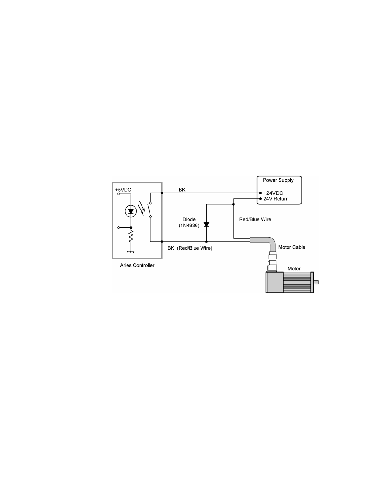
Parker Hannifin
Motors without Full Wave Rectifiers
When using Parker MaxPlus motors, Parker motors with serial numbers less
than 010904xxxxx, or non-Parker motors, you must install a fly-back diode.
Consult the specifications or the manufacturer of your motor.
Connecting the Brake Relay
1. Connect one red/blue brake wire (Parker Motor cable or equivalent) to
the BK terminal of the Motor connector (Aries drive).
2. Connect the second red/blue brake wire (Parker Motor cable or
equivalent) to the 24V return on your power supply.
3. Between the two red/blue wires, connect the fly-back diode. See
Figure 24.
Connect the +24 VDC power supply to the second BK terminal of the
4.
Motor connector (Aries drive).
Figure 24 shows a typical installation.
52 Aries User Guide
Figure 24 Brake Relay Connection for Non-Parker Motors
Page 53
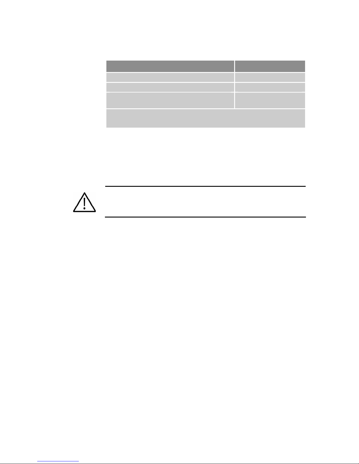
Parker Hannifin
Relay Operation
Drive Condition Relay State
Enabled Closed (conducting)
Faulted Open
No AC power on L1 and L2*, or drive not
enabled
* Mains Control power on C1 and C2 does not affect the relay. With mains power applied
to C1 and C2, the relay remains open if AC power is not applied to the L1 and L2
terminals.
Table 20 Brake Relay Operation
Open
Relay Specifications
Relay Type .............................................. Solid State Relay
Normally open
Relay Maximum Rating........................... 1 Amp at 24 VDC
Warning — Do not exceed the ratings of the brake relay. If required,
control a suitable external relay with this relay to meet your power
requirements.
Chapter 3 Electrical Installation 53
Page 54
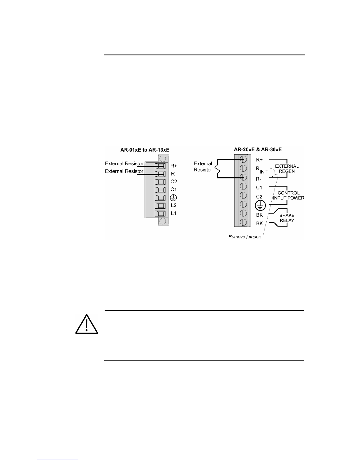
Parker Hannifin
Regeneration Protection
The Aries drive models AR-20xE and AR-30xE have internal regeneration
power dump (dissipation) resistors. Models AR-01xx through AR-13xx do
not. However, all models can utilize an external regeneration resistor.
Regeneration Connection
To use a external regeneration (power dump) resistor, connect your external
resistor to the R+ and R- terminals as follows:
• For models AR-01x to AR-13xx, use the Mains connector.
• For models AR-20xE and AR-30xE, use the Control connector.
Figure 25 illustrates the external regeneration resi
stor connections.
Figure 25 External Regeneration Connection
Important! For models AR-20xE and AR-30xE, you must remove the
factory-installed link between R
external regeneration resistor. (Otherwise the internal regeneration
resistor will still be in the circuit, and its thermal protection circuit limits
the performance).
For information on selecting a suitable external regeneration (power dump)
resistor, see “Appendix B External Power-Dump Resistor Selection.”
Warning — The drive’s connector strip terminals are at hazardous voltages
when power is applied to the drive, and up to several minutes after power is
removed. Lower voltages may still be present for several minutes after power
is removed.
During normal operation, these high voltage terminals must not be accessible
to the user.
and R− when you connect the
INT
54 Aries User Guide
Page 55
Parker Hannifin
Internal Regeneration Capability
The internal regeneration resistor of the AR-20xE and AR-30xE is capable of
dissipating 1kW for 1 second and up to 100 Watts continuously (depending
upon heatsink temperature). If the calculated temperature of the internal
regeneration resistor exceeds 150°C (302°F), the drive turns off the
regeneration circuit and may experience an over-voltage fault.
Similarly, models AR-01xx through AR-13xx may experience an over-voltage
fault if the regeneration exceeds the absorbent capacity of the drive’s internal
bus capacitors, as shown in Table 21.
Regeneration Absorption
The available absorption varies based on mains voltage and the drive’s
internal capacitance. The drives can absorb the following amounts of
regenerated energy in their internal capacitors:
Drive Absorb (Joules)
120 VAC
Absorb (Joules)
240 VAC
AR-01xx 28 9
AR-02xx 43 14
AR-04xx 57 19
AR-08xx 72 24
AR-13xx 104 35
AR-20xE N/A 50
AR-30xE N/A 50
Table 21 Regeneration Absorption
For more specifications about energy absorption by the Aries drive’s
capacitors, see Table 58.
For mo
re information about selecting an external power-dump resistor, see
“Appendix B External Power-Dump Resistor Selection”.
Chapter 3 Electrical Installation 55
Page 56
Parker Hannifin
LEDs⎯Drive Status Indicators
The drive has two bi-color LEDs. The LED on the left displays yellow or
green colors; The LED on the right displays red or green colors. The
following tables describe LED illumination states and the conditions they
indicate.
Normal Operation
LED–Left LED–Right What it means
Off Green Power on, enabled
Yellow Green Power on, regeneration active
Off Red Power on, disabled–No Fault
Yellow Off Power on, boot process
Off Red (flashing) Waiting for OS download
Yellow (flashing) Red (flashing) OS download in process
Table 22 LED Status Indicator-Normal Operation
Internal Drive Faults
LED–Left LED–Right What it means
Yellows Red
Yellow & 1 Green (flashing) Red Bridge Fault
Yellow & 2 Green (flashing) Red Feedback Fault
Yellow & 3 Green (flashing) Red Thermal Fault
Yellow & 4 Green (flashing) Red Other Fault
Yellow & 5 Green (flashing) Red Encoder Loss
Table 23 LED Status Indicator-Internal Drive Fault
Control power
mode active
56 Aries User Guide
Page 57
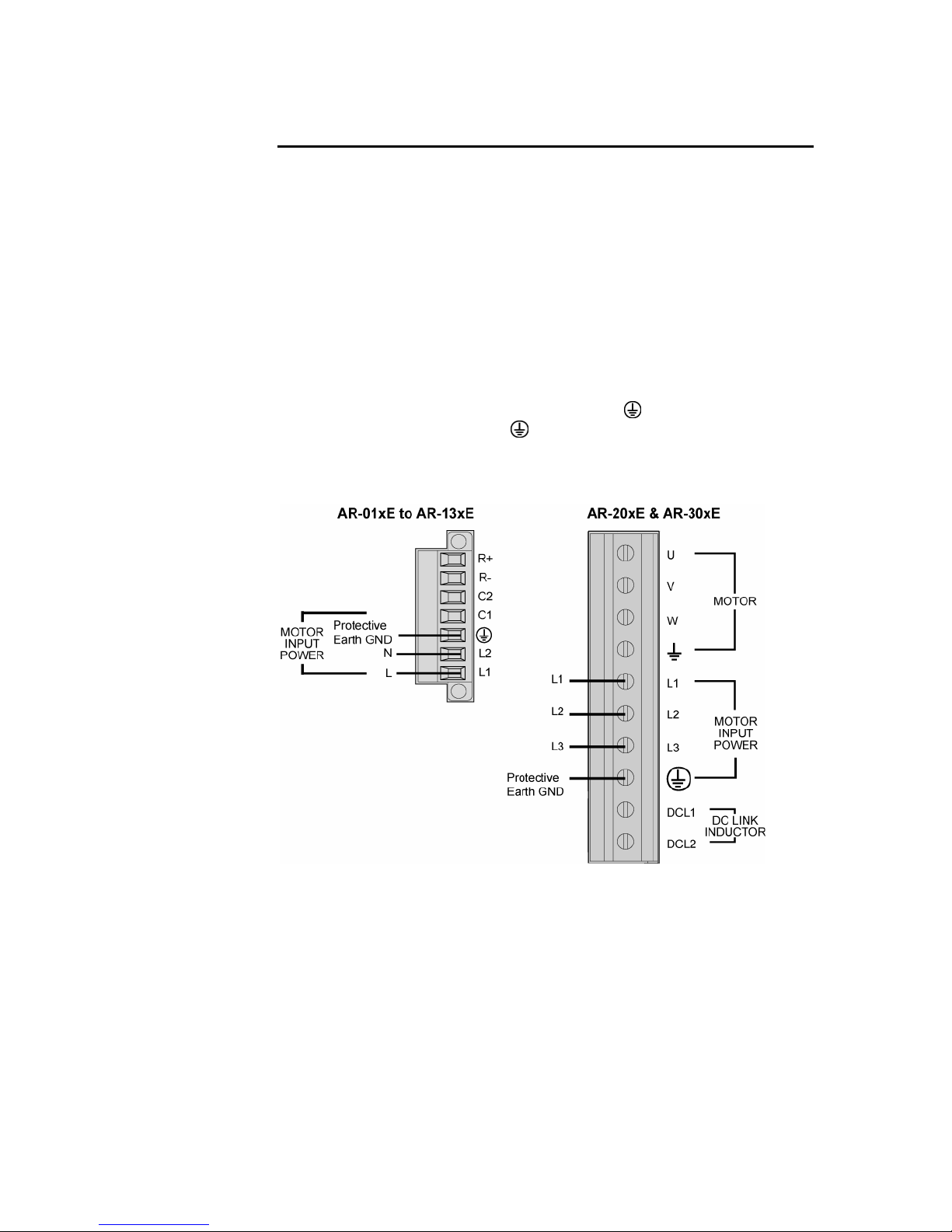
Parker Hannifin
Connector Descriptions
Motor Mains Power Connector
The drive’s Mains screw terminal connector provides a connection for AC
Mains power to your drive. (For connection information, see “Input Power” on
page 39.) The c
the others. Specifications for the connectors follow in this section.
On models AR-01xx through AR-13xx, the Mains connector also serves as a
connector for Control power (C1 and C2) and a power dissipation resistor
(R+ and R–). For more information on these additional connections, see
“Control Power Supply” on page 46 “Regeneration Protection” on page 54.)
connector is removable.
This
On models AR-20xE and AR-30xE, the Motor/Power connector serves as the
connector for Motor Mains power (L1, L2, L3, and
power to the motor (U, V, W, and
information on these additional connections, see “Output Power” on page 43
and “External DC Link Inductor (Optional)” on page 45. This co
removable.
onnector differs between the two largest Aries models and
), as well as for output
) and a DC Link Inductor. For more
nnector is not
Figure 26 Mains/Input Power Connector
Chapter 3 Electrical Installation 57
Page 58

Parker Hannifin
Mains/Input Power Connector
AR-01xx, AR-02xx,
AR-04xx, AR-08xx, AR-13xx................. Amphenol PCD: OSTTJ075102
Parker Hannifin Part Number.................. 43-021069-01
Connector Type.......................................Removable screw terminal
Terminals ........................................7
Pitch ................... 0.200 in (5.08 mm)
Wire Range....................12-26 AWG
.......................................14-27 SWG
................................(0.12-3.30 mm
Wire Strip length .. 0.31 in (7.87 mm)
Torque....7.0 in–lbs nom. (0.79 N-m)
AR-20xE, AR-30xE ................................ Molex: 39960-0110
Parker Hannifin Part Number.................. N/A
Connector Type.......................................Non-Removable screw terminal
Terminals ......................................10
Pitch ........................ 0.315 in (8 mm)
Wire Range....................10-22 AWG
.......................................12-23 SWG
....................................(0.5-4.0 mm
Wire Strip length .... 0.25 in (6.5 mm)
Torque....7.0 in–lbs nom. (0.79 N-m)
2
)
2
)
58 Aries User Guide
Page 59
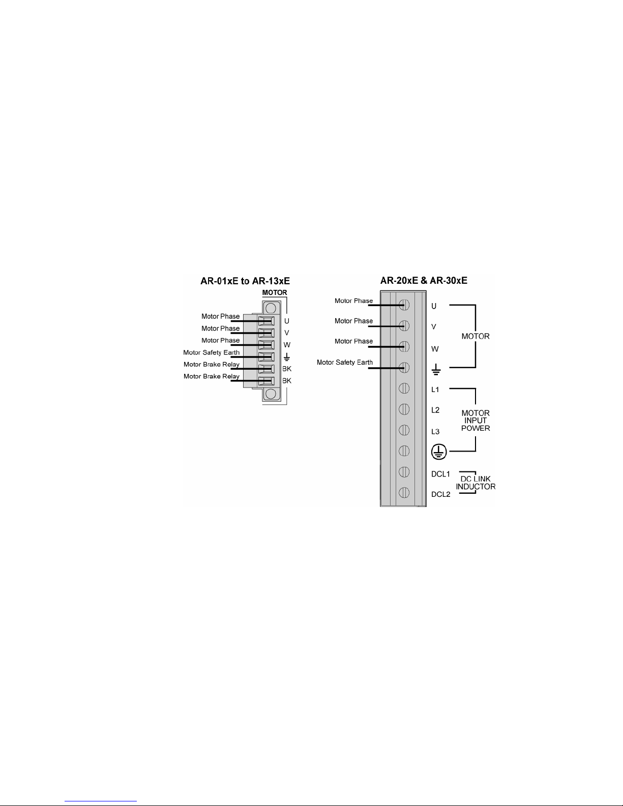
Parker Hannifin
Output Power Connector
The drive’s Motor screw terminal connector provides output power to your
motor. (For connection information, see “Output Power” on page 43.) The
nector differs between the two largest Aries models and the others.
con
Specifications for the connectors follow in this section.
On models AR-01xx through AR-13xx, the Motor connector also serves to
connect an external motor brake to the drive’s internal solid-state relay (BK).
For information on this connection, see “Brake Relay (Optional)” on page 50.
connector is removable.
This
On models AR-20xE and AR-30xE, the M
OTOR/POWER connector serves as
the connector for output power to the motor, as well as for Mains power (VAC
Input Power) and a DC Link Inductor. For information on these additional
connections, see “Input Power” on page 39 and “External DC Link Inductor
(Option
al)” on page 45. This co
nnector is not removable.
Figure 27 Output (MOTOR) Power Connector
Chapter 3 Electrical Installation 59
Page 60

Parker Hannifin
Motor Connector
AR-01xx, AR-02xx, AR-04xx,
AR-08xx, AR-13xx ................................. Amphenol PCD: OSTTJ075102
Parker Hannifin Part Number.................. 43-021068-01
Connector Type.......................................Removable screw terminal
Terminals ........................................6
Pitch ................... 0.200 in (5.08 mm)
Wire range .....................12-26 AWG
.......................................14-27 SWG
................................(0.12-3.30 mm
Wire strip length...... 0.310 in (8 mm)
Torque....7.0 in–lbs nom. (0.79 N-m)
AR-20xE, AR-30xE ................................ Molex: 39960-0110
Parker Hannifin Part Number.................. N/A (not replaceable)
Connector Type.......................................Non-Removable screw terminal
Terminals ......................................10
Pitch ........................ 0.315 in (8 mm)
Wire range .....................10-22 AWG
.......................................12-23 SWG
....................................(0.5-4.0 mm
Wire strip length..... 0.25 in (6.5 mm)
Torque....7.0 in–lbs nom. (0.79 N-m)
2
)
2
)
60 Aries User Guide
Page 61

Parker Hannifin
AR-20xE & AR30xE Control Connector
On the AR-20xE & AR 30xE models, the Control connector serves for three
connections: an external power dump resistor (E
power circuit (C
ONTROL INPUT POWER), and a safety brake relay (BRAKE
RELAY). The connector is an eight-position non-removable screw terminal.
Specifications for the connector follow in this section.
XTERNAL REGEN), a control
The Control connector has a factory-installed link between R
and R− for an
INT
internal regeneration resistor, which provides thermal protection. For more
information, see “Regeneration Protection” on page 54. For inform
additional connections, see “Control Power Supply” on page 46 an
ation on
d “Brake
Relay (Optional)” on page 50.
Figure 28 AR-20xE & AR30xE Control Connector
AR-20xE, AR-30xE ................................ PCD: ELM021100
Parker Hannifin Part Number.................. N/A (not replaceable)
Connector Type.......................................Non-Removable screw terminal
Terminals ........................................8
Pitch ...................... 0.400 in (10 mm)
Wire Range....................12-28 AWG
.......................................14-29 SWG
................................(0.12-3.30 mm
Wire Strip length 0.250 in (6.35 mm)
2
)
Chapter 3 Electrical Installation 61
Page 62
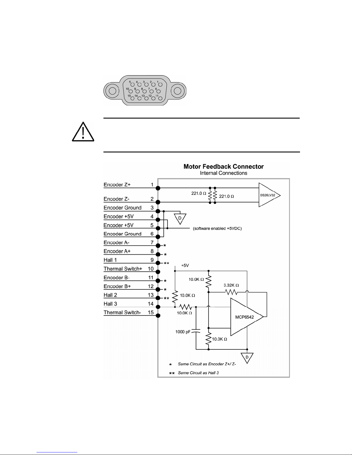
Parker Hannifin
Motor Feedback Connector—Encoder
Inputs for the resolver feedback, motor thermal switch, and hall effects are
located on the 15-pin Motor Feedback connector.
Figure 29 MOTOR FEEDBACK connector, female drive connector pinout
Important — Encoder inputs use a DS26LV32 differential line receiver.
Parker Hannifin recommends 26LS31 (or compatible) differential line driven
encoders.
Single ended encoders are not compatible.
Figure 30 MOTOR FEEDBACK connector, internal circuit diagram
62 Aries User Guide
Page 63
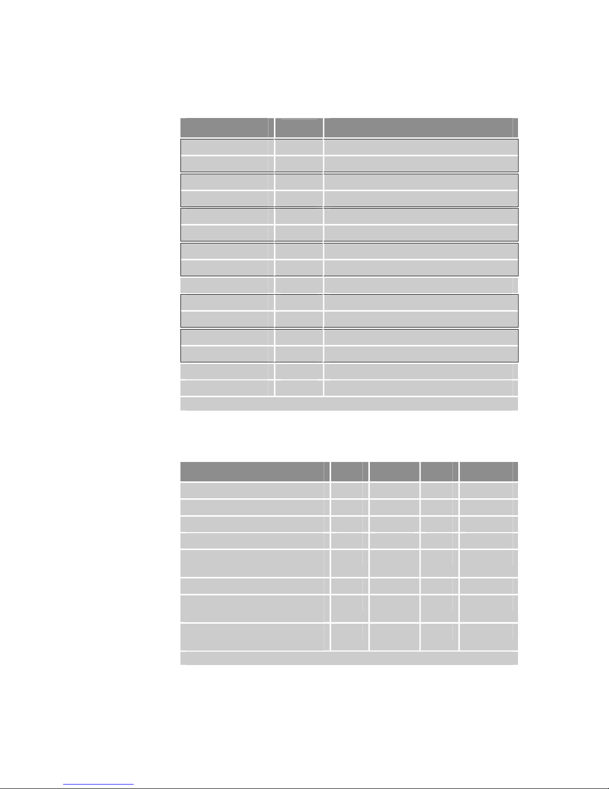
Parker Hannifin
Pinout—MOTOR FEEDBACK Connector
Note: A box surrounding pins indicates a requirement for twisted pair wiring.
Signal
Pin
Description
ENC Z+ / Data+ 1 Encoder Z Channel in
ENC Z– / Data– 2 Encoder Z Channel in
DGND 3 Encoder power return
+5 VDC 4 +5 VDC Encoder power
+5 VDC 5 +5 VDC Hall power
DGND 6 Hall power return
ENC A– / SIN– 7 Encoder A Channel in
ENC A+ / SIN+ 8 Encoder A Channel in
Hall 1 / SCLK+ * 9 Hall 1 input
Thermal+ 10 Motor thermal switch/thermistor
Thermal– 15 Motor thermal switch/thermistor
ENC B / COS– 11 Encoder B Channel in
ENC B+ / COS+ 12 Encoder B Channel in
Hall 2 / SCLK– * 13 Hall 2 input
Hall 3 14 Hall 3 input
* When using the SinCos protocol, pins 9 and 13 require twisted pair wiring.
Table 24 MOTOR FEEDBACK Connector Pinout
Inputs—Encoder
Description Min Typical Max Units
Common Mode Range -7 +7 V
Current—Encoder 250 mA
Current—Hall 250 mA
Differential Threshold Voltage -200 +200 mV
Differential Termination
Impedance
Thermal Switch Current 2 mA
Thermal Switch Voltage
Maximum (supplied)
Input Frequency
(pre-quadrature)
Note: All parameters are at the connector pin.
Table 25 Inputs—Encoder Inputs Electrical/Timing Characteristics
120 ohms
15 V
5 MHz
Chapter 3 Electrical Installation 63
Page 64

Parker Hannifin
Connector Specification—Aries Drive
Manufacturer........................................... KYCON or equivalent
Connector Type.......................................15-Pin High Density
D-Subminiature
(female socket)
KYCON Part Number.............................. K66-E15S-NR
Connector Specification—Mating Connector
Mating connectors are not provided with Aries drives. Parker cables are
available with mating connectors attached.
Manufacturer........................................... AMP or equivalent
Connector Type.......................................15-Pin High Density D-Subminiature
(male connector)
Cable Kit.................................................. AMP Part Number 748473-1
Includes: 748364-1 connector,
shield, enclosure, and two jack
screws
(does not include contacts or
ferrules)
Contacts ..................................................Crimp style
30µ” Gold—AMP Part Number
748333-4
Gold Flash—Amp Part Number
748333-7
64 Aries User Guide
Page 65
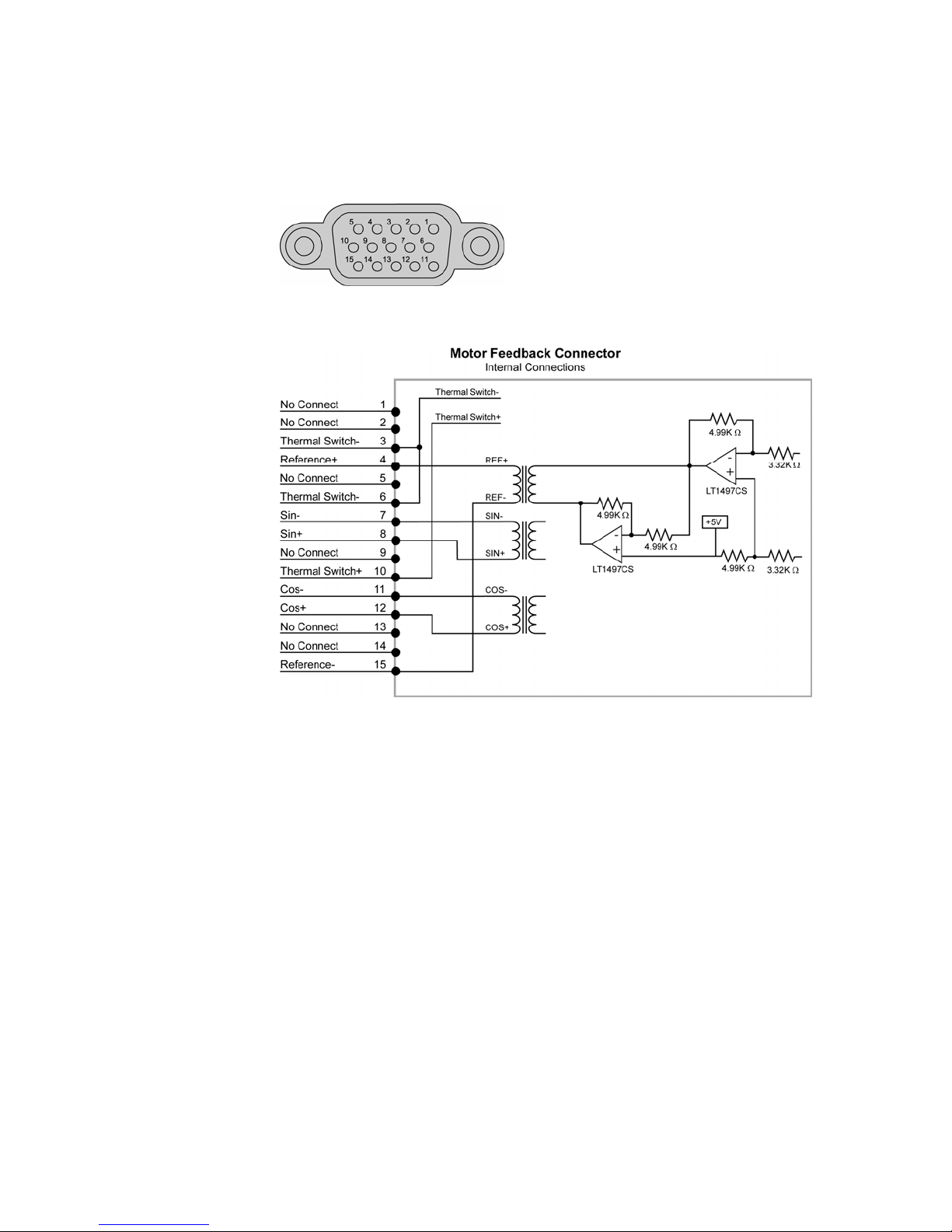
Parker Hannifin
Motor Feedback Connector—Resolver
Inputs for the encoder feedback, motor thermal switch, and hall effects are
located on the 15-pin Motor Feedback connector.
Figure 31 MOTOR FEEDBACK connector, female drive connector pinout
Figure 32 MOTOR FEEDBACK connector for resolver option, internal circuit diagram
Chapter 3 Electrical Installation 65
Page 66
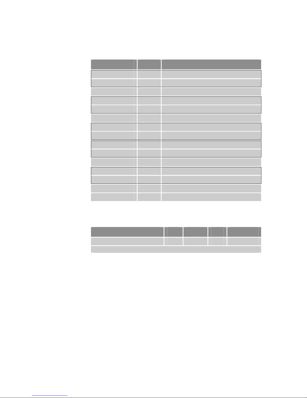
Parker Hannifin
Pinout—MOTOR FEEDBACK Connector for Resolver Option
Note: A box surrounding pins indicates a requirement for twisted pair wiring.
Signal Pin Description
No connection 1 —
No connection 2 —
Thermal- 3 Motor thermal switch/thermistor
Reference+ 4 Resolver excitation signal
Reference- 15 Resolver excitation signal
No connection 5 —
Thermal- 6 Motor thermal switch/thermistor
Thermal+ 10 Motor thermal switch/thermistor
SIN– 7 SIN resolver feedback signal
SIN+ 8 SIN resolver feedback signal
No connection 9 —
COS– 11 COS resolver feedback signal
COS+ 12 COS resolver feedback signal
No connection 13 —
No connection 14 —
Table 26 MOTOR FEEDBACK Connector Pinout for Resolver Option
Resolver Excitation
Description Min Typical Max Units
Excitation Frequency — 10 — KHz
Note: All parameters are at the connector pin.
Table 27 Resolver excitation
Drive I/O Connector
The inputs and outputs (I/O) located on the 26-pin DRIVE I/O connector are
described below. For preparing your own cable, use differential pair wiring
with a minimum of three turns-per-inch (3 TPI).
Optical Isolation
The following describes which differential I/O signals are optically isolated:
• Enable input is optically isolated with both Anodes (+) and Cathodes
• Reset input is optically isolated with both Anodes (+) and Cathodes
66 Aries User Guide
(–) available.
(–) available.
Page 67
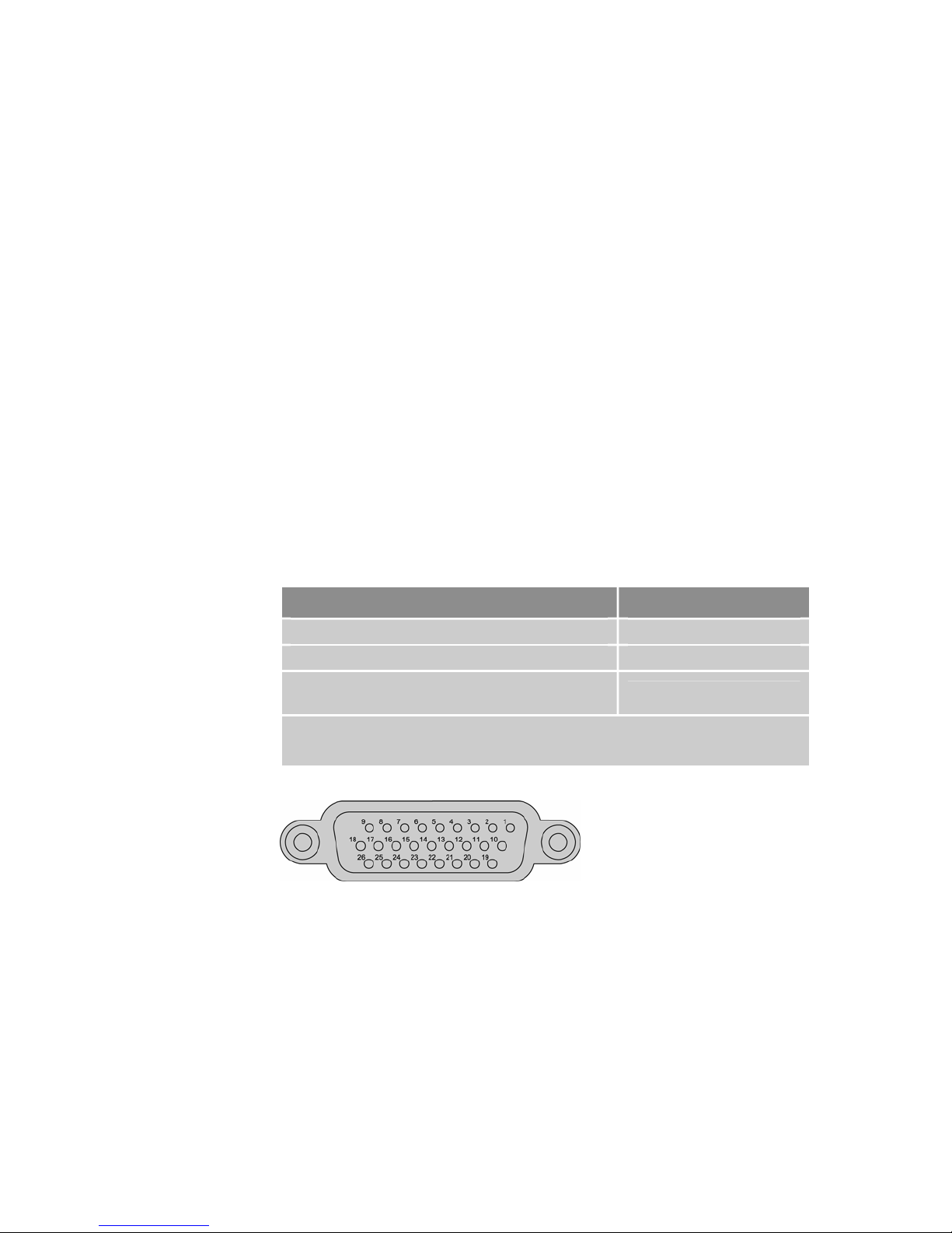
Parker Hannifin
• Fault output is optically isolated with both Collector (+) and Emitter
(–) available.
No Optical Isolation
The following describes which I/O signals are not optically isolated:
• Step and Direction inputs are 5V differential compatible (RS-422
logic level compatible.
• Encoder output signals are non-isolated RS-422 compatible
differential drivers referenced to DGND.
• RS-485 is non-isolated RS-485 compatible differential signals
referenced to DGND.
• AIN+ Analog input is single-ended non-isolated referenced to AIN–,
and common mode referenced to DGND.
Fault Operation
When the Aries Drive is enabled and there are no fault conditions, the Fault
circuit is closed (conducting). However, the following circumstances can trip
the Fault circuit: a fault condition is present (see “Error Messages” on page
160); the Ena
from the drive.
ble circuit is open (see Figure 34); or, Mains power is removed
You can use the LED status indicators to help identify internal drive faults.
For more information, see Table 23.
Drive Condition Fault Output
Enabled Closed (conducting)
Faulted Open
No AC power on L1 and L2*,
or drive not enabled
* Mains Control power on C1 and C2 does not affect the fault circuitry. With mains power
applied to C1 and C2, the fault circuit remains open if AC power is not applied to the L1
and L2 terminals.
Table 28 Fault Output Operation
Open
Figure 33 DRIVE I/O connector, female drive connector pinout
Chapter 3 Electrical Installation 67
Page 68
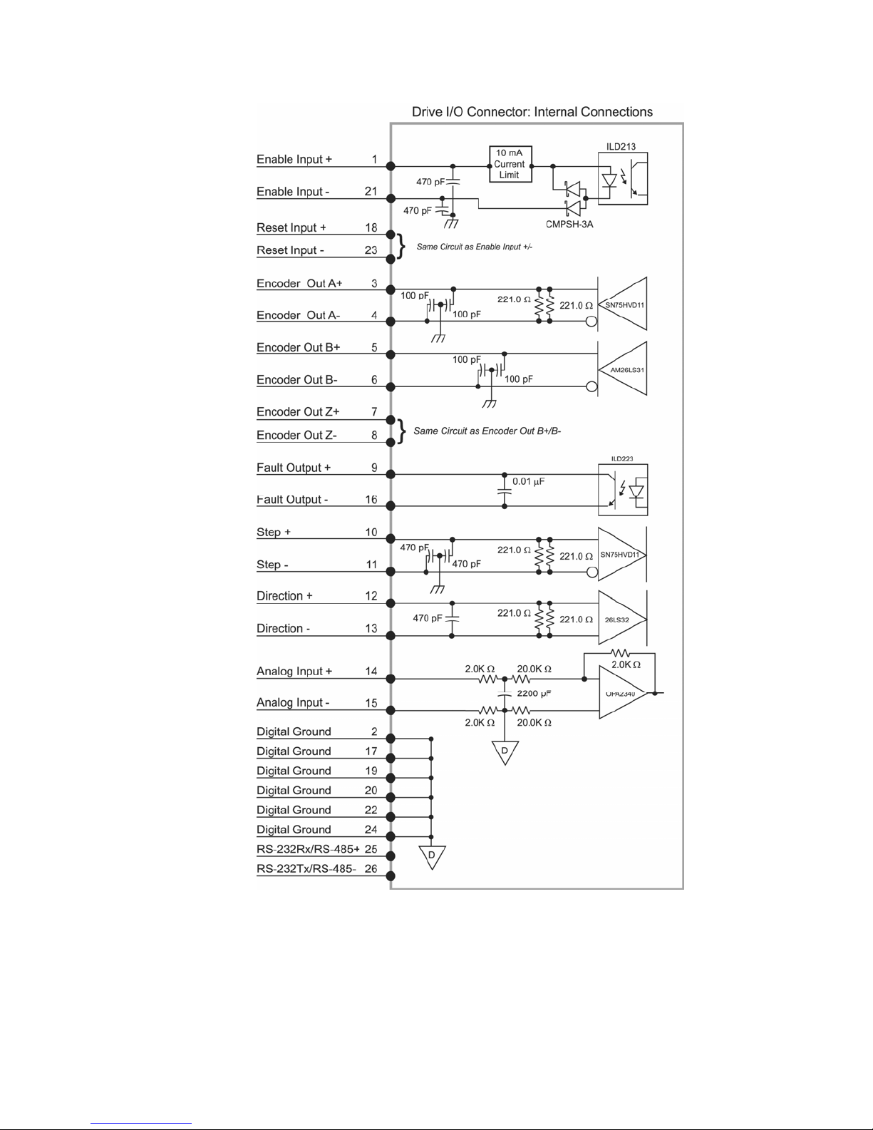
Parker Hannifin
Figure 34 DRIVE I/O connector, internal circuit diagram
68 Aries User Guide
Page 69
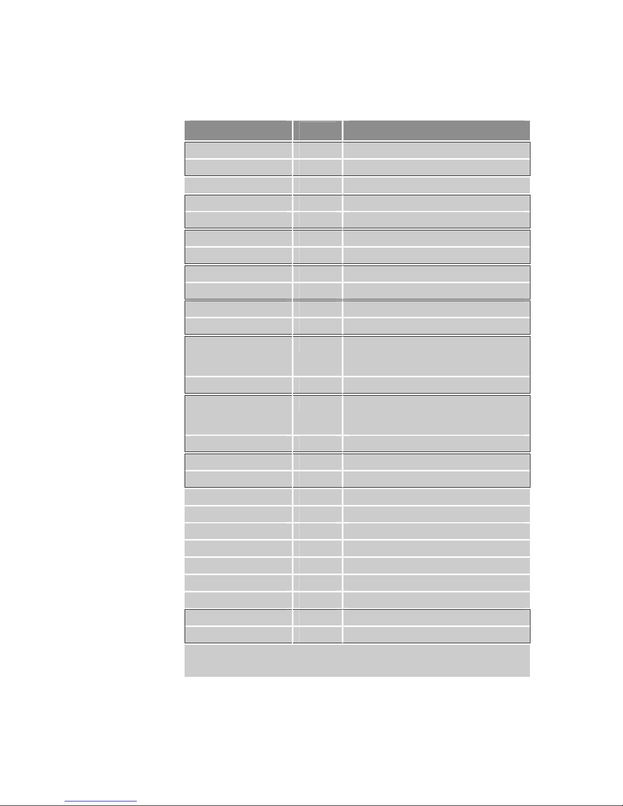
Parker Hannifin
Pinout—DRIVE I/O Connector
Note: A box surrounding pins indicates a requirement for twisted pair wiring.
Signal
Pin
Description
ENABLE+ 1 Drive Enable input anode
ENABLE– 21 Drive Enable input cathode
DGND 2 Digital ground
ENC A+ 3 Encoder A Channel out
ENC A– 4 Encoder A Channel out
ENC B+ 5 Encoder B Channel out
ENC B– 6 Encoder B Channel out
ENC Z+ 7 Encoder Z Channel out (Index +)
ENC Z– 8 Encoder Z Channel out (Index – )
FAULT+ * 9 Fault Output collector
FAULT– 16 Fault Output emitter
STEP+ 10
5V Differential compatible (RS-422
logic level compatible) position
command
STEP– 11 Position command return
DIRECTION+ 12
5V Differential compatible (RS-422
logic level compatible) direction
command
DIRECTION– 13 Direction command return
AIN+ 14 Analog ±10V current command
AIN– 15 ±10V return
DGND 17 Digital Ground
RESET+ 18 Drive Reset input anode
RESET– 23 Drive Reset input cathode
DGND 19 Digital Ground
DGND 20 Digital Ground
DGND 22 Digital Ground
DGND 24 Digital Ground
RS-232Rx/ RS-485+ 25 RS-232Rx/ RS-485+ Half-Duplex
RS-232Tx/ RS-485– 26 RS-232Tx/ RS-485– Half-Duplex
* Opto is ON and conducting when no fault condition is present. When a fault occurs, the
opto turns OFF and the transistor does not conduct current. This simulates a normally
open relay. For more information, see Table 20.
Table 29
DRIVE I/O Connector Pinout
Chapter 3 Electrical Installation 69
Page 70
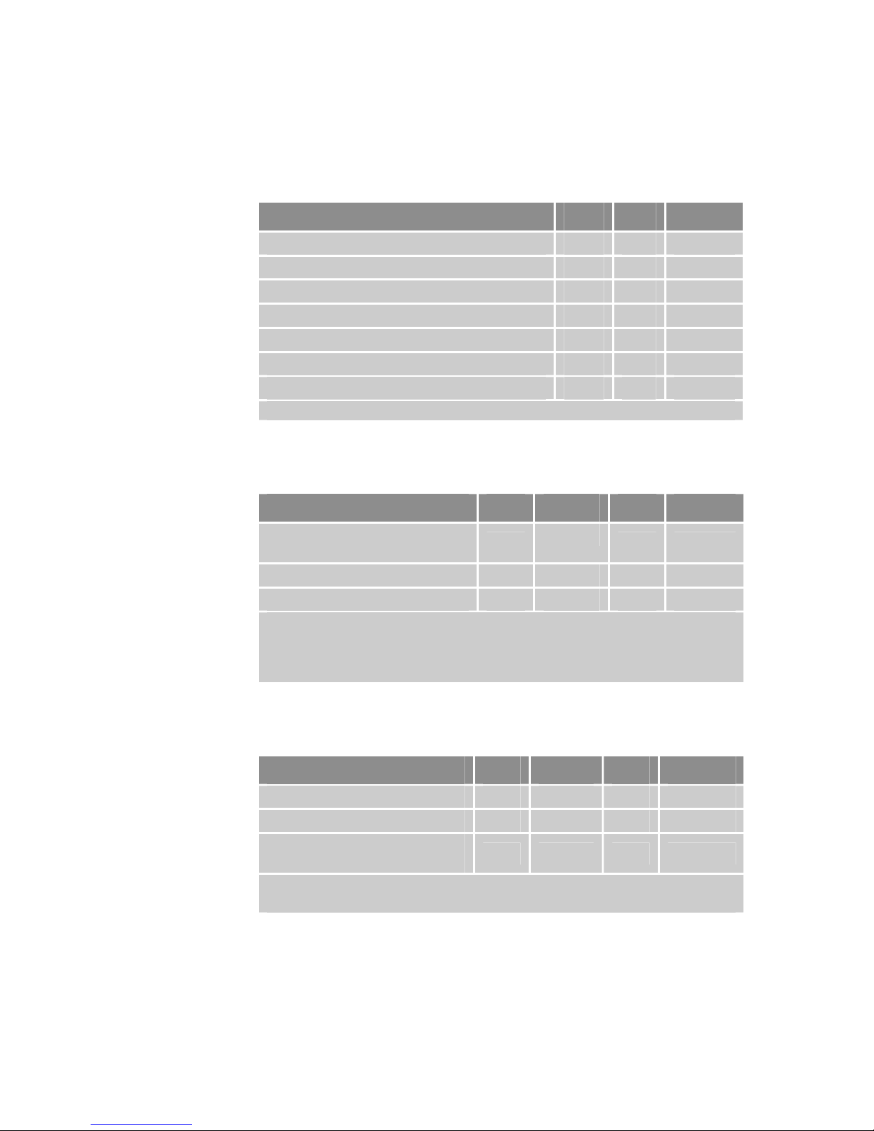
Parker Hannifin
Inputs—Enable, Reset
The drive Enable and Reset inputs are optically isolated inputs. Current is
limited internally for input voltage control of 5 to 24 volt logic. The Anode (+)
and Cathode (−) are on separate connector pins to allow significant flexibility
in wiring to different styles of interface.
Description Min Max Units
Turn-on time – 1 ms
Turn-off time – 1 ms
Guaranteed on voltage 4 – VDC
Guaranteed off voltage – 2 VDC
Maximum forward voltage – 30 VDC
Maximum reverse voltage -30 – VDC
Forward current 3 12 mA
Note: All parameters are at the connector pin.
Table 30 Inputs—Enable and Reset Electrical/Timing Characteristics
Outputs—Encoder
Description Min Typical Max Units
Output Frequency
(pre-quadrature)
5 MHz
Input Voltage High * 2.4 V
Input Voltage Low * 0.5 V
* Based on 120Ω differential load impedance.
Note: All parameters are at the connector pin.
Note: Aries encoder is a hardware pass-through; therefore, you cannot change output
resolution.
Table 31 Outputs—Encoder Outputs Electrical/Timing Characteristics
Outputs—Fault
Description Min Typical Max Units
Blocking Voltage 30 V
Continuous Load Current 10 mA
Output Saturation Voltage
(at 1.0 mA)
* Based on 120Ω differential load impedance.
Note: All parameters are at the connector pin.
1.0 V
Table 32 Outputs— Fault outputs Electrical/Timing Characteristics
70 Aries User Guide
Page 71
Parker Hannifin
Inputs—Step & Direction
Description Min Typical Max Units
Common Mode Range -7 +7 V
Differential Threshold Voltage -200 +200 mV
Differential Termination
Impedance
120
ohms
Input Frequency (pre-quadrature) 5 MHz
Note: All parameters are at the connector pin.
Table 33 Inputs—Step & Direction Electrical/Timing Characteristics
Inputs—Analog
Description Min Typical Max Units
Function Input Range -10 +10 V
Resolution 14 bits
Impedance >20 K ohms
Note: All parameters are at the connector pin.
Table 34 Inputs—Analog Electrical/Timing Characteristics
Connector Specification—Aries Drive
Manufacturer........................................... KYCON or equivalent
Connector Type.......................................26-Pin High Density
D-Subminiature
(female socket)
KYCON Part Number.............................. K66-A26S-NR
Connector Specification—Mating Connector
Mating connectors are not provided with Aries drives. Parker cables are
available with mating connectors attached.
Manufacturer........................................... AMP or equivalent
Connector Type.......................................26-Pin High Density D-Subminiature
(male connector)
Cable Kit.................................................. AMP Part Number 748474-1
Includes: 748365-1 connector,
shield, enclosure, and two jack
screws (does not include contacts or
ferrules)
Contacts ..................................................Crimp style
30µ” Gold—AMP Part Number
748333-4
Gold Flash—Amp Part Number
748333-7
Chapter 3 Electrical Installation 71
Page 72
Parker Hannifin
Installation Test
Once you have made the necessary mechanical and electrical connections,
you can test the drive. The Aries Support Tool contains the Auto Run Test
Wizard, which exercises basic functions of the Aries drive.
You must do the following before testing the drive:
• Configure the drive for the motor to which it is connected. Resolve
any configuration errors before proceeding with the test.
• Enable the drive.
• If the Aries drive is connected to a controller, disable the controller’s
servo loop.
• If the motor is connected to a load, disconnect the motor so that it is
free to turn unimpeded.
Safety Warning — High-performance motion control equipment is capable
of producing rapid movement and very high forces. Unexpected motion may
occur especially during the development of controller programs. KEEP WELL
CLEAR of any machinery driven by stepper or servo motors. Never touch
any part of the equipment while it is in operation.
Testing the Aries Drive
If the Aries drive has been installed correctly, the motor will spin at one
revolution per second. If the motor does not spin, a wiring or configuration
error possibly exists.
1. Start the Aries Support Tool.
2. Under Menu, click Operating System Update.
3. Click Auto Run Test Wizard.
72 Aries User Guide
Page 73

Chapter 4 Communications
CHAPTER FOUR
Communications
Terminal Emulator Configuration............................................................... 74
Establishing Communic
RS-232 Communications
RS-485 Communications
RS-485 Multi-Drop
RS-232/485 Dongle for Communic
IN THIS CHAPTER
ations ...................................................................74
...........................................................................75
...........................................................................75
..................................................................................... 76
ations Setup .......................................77
Page 74
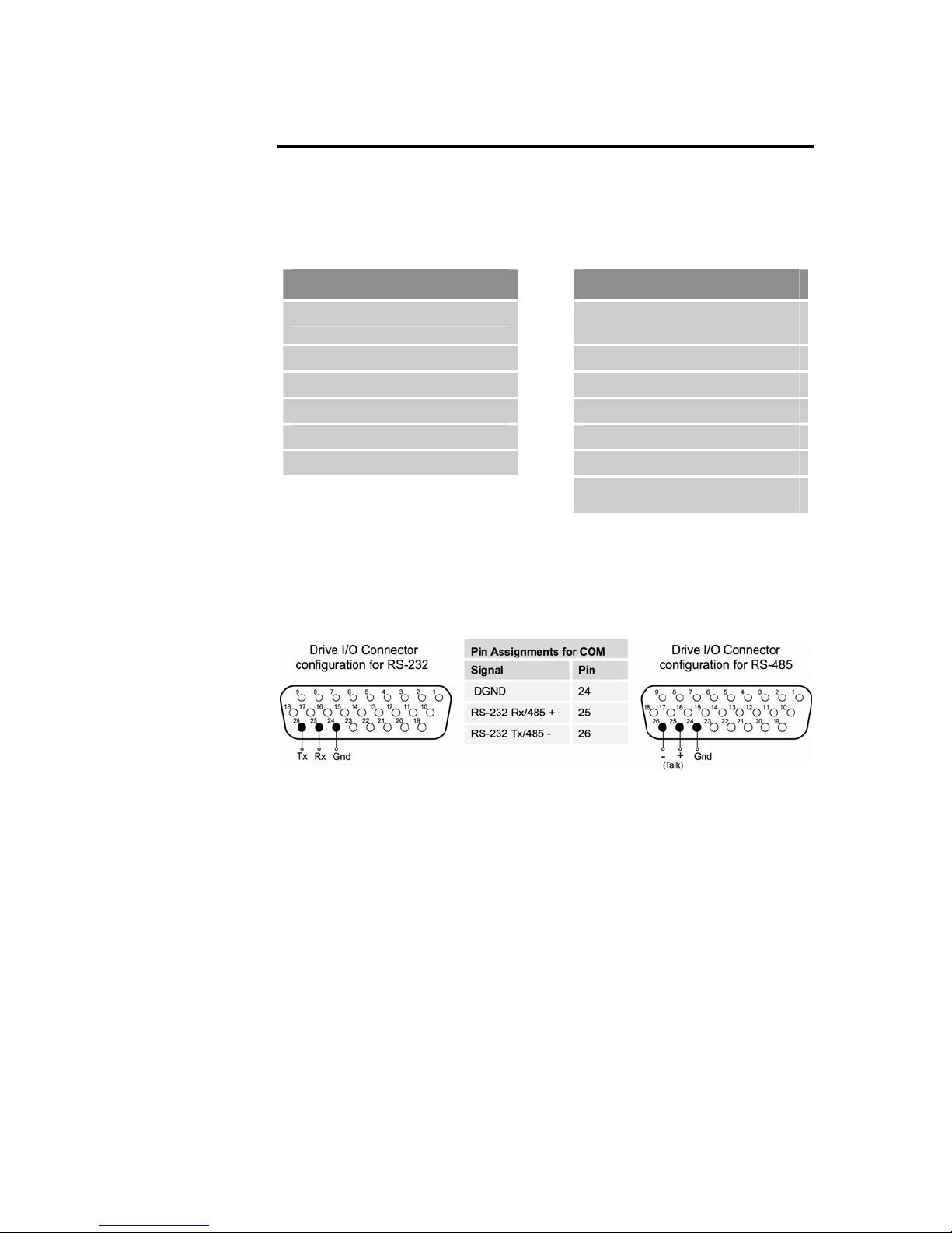
Parker Hannifin
RS-232/485 Communications
The Aries drive has a single serial port, located on the DRIVE I/O connector on
the front of the unit. This chapter refers to it as the COM port. The Aries drive
uses ASCII and the RS-232 or RS-485 communication protocols.
Terminal Emulator Configuration
RS-232 RS-485 *
Rx, Tx, Gnd
9600 baud 9600 baud
8 data bits 8 data bits
1 stop bit 1 stop bit
No parity No parity
Full-duplex Half-duplex
* Twisted pair cabling recommended
2-wire plus ground
(Talk+, Talk–, Gnd)
(e.g. Belden 9842)
Table 35 Terminal Emulator Configuration for RS-232/485 Communication
Establishing Communications
The 26-pin DRIVE I/O connector (female D-subminiature) also functions as the
COM port. You can use it with RS-232 or two-wire RS-485 communications.
Figure 35 RS-232/485 Connections
For setup purposes, you can connect a personal computer (PC) directly to
the Aries drive through its COM port. Before attempting to communicate with
the Aries drive, verify your PC’s connector pinout—make sure the cable
connects the following:
• The PC’s transmit terminal (pin 3 of the 9-pin connector) to the
Aries’s receive terminal (pin 25).
• The PC’s receive terminal (pin 2 of the 9-pin connector) to the
Aries’s transmit terminal (pin 26).
• The PC’s ground terminal to the Aries’s ground terminal (pin 24).
You can also use the Aries Drive I/O Dongle (sold separately), which allows
a PC to simultaneously communicate with the Aries drive while also
connected to a controller. For more information, see “RS-232/485 Dongle for
unications Setup” on page 77.
Comm
74 Aries User Guide
Page 75

Parker Hannifin
Depending on the communications protocol you are using, Aries can
automatically configure itself.
• If using RS-232, Aries will automatically detect and configure itself
for that communications protocol.
• If using RS-485 (two-wire) and the standard bias configuration,
Aries will automatically detect and configure itself for that
communications protocol.
For automatic detection to work, the RS-485 network must be
configured with an up bias on + (Talk) and a down bias on – (Talk).
RS-232 Communications
The Aries drive supports RS-232 communication. However, you cannot
connect the drive in an RS-232 daisy chain.
Pinout for RS-232 Communication
Pin Description
25 Rx (receive). Connect to Tx on your computer.
26 Tx (transmit). Connect to Rx on your computer.
24 DGND* (logic ground). Connect to DGND on your computer.
Maximum RS-232 cable length is 50 feet (15.25 meters).
* Many PC COM ports connect RS-232 ground to chassis ground.
Table 36 RS-232 Connector Pinout
RS-485 Communications
The Aries is designed to use RS-485 half-duplex (two-wire). In addition, you
can use it in multi-drop networks. For more information about multi-drop, see
“RS-485 Multi-Drop” on page 76.
Pinout for 2-wire RS-485 Communication
Pin Description
25 Connect to Tx/Rx+ on your computer.
26 Connect to Tx/Rx– on your computer.
24 DGND* (logic ground). Connect to DGND on your computer.
• Maximum RS-485 cable length is 1000 feet (305 meters).
• Keep wires as short as possible. Termination resistors may be required on long
cable runs.
• Connect RS-485 cables before applying power to the drive.
(Reconnecting the cables with power applied may cause the drive to interpret
intermittent connections as RS-232 hardware handshake signals; this may result
in shutdown of the RS-485 interface. If this happens, reset the drive to re-enable
the RS-485 interface.)
• Recommended cable: Belden 9842.
* Many PC COM ports connect RS-485 ground to chassis ground.
Table 37 RS-485 Connector Pinout
For connection information, see Figure 36.
Chapter 4 Communications 75
Page 76
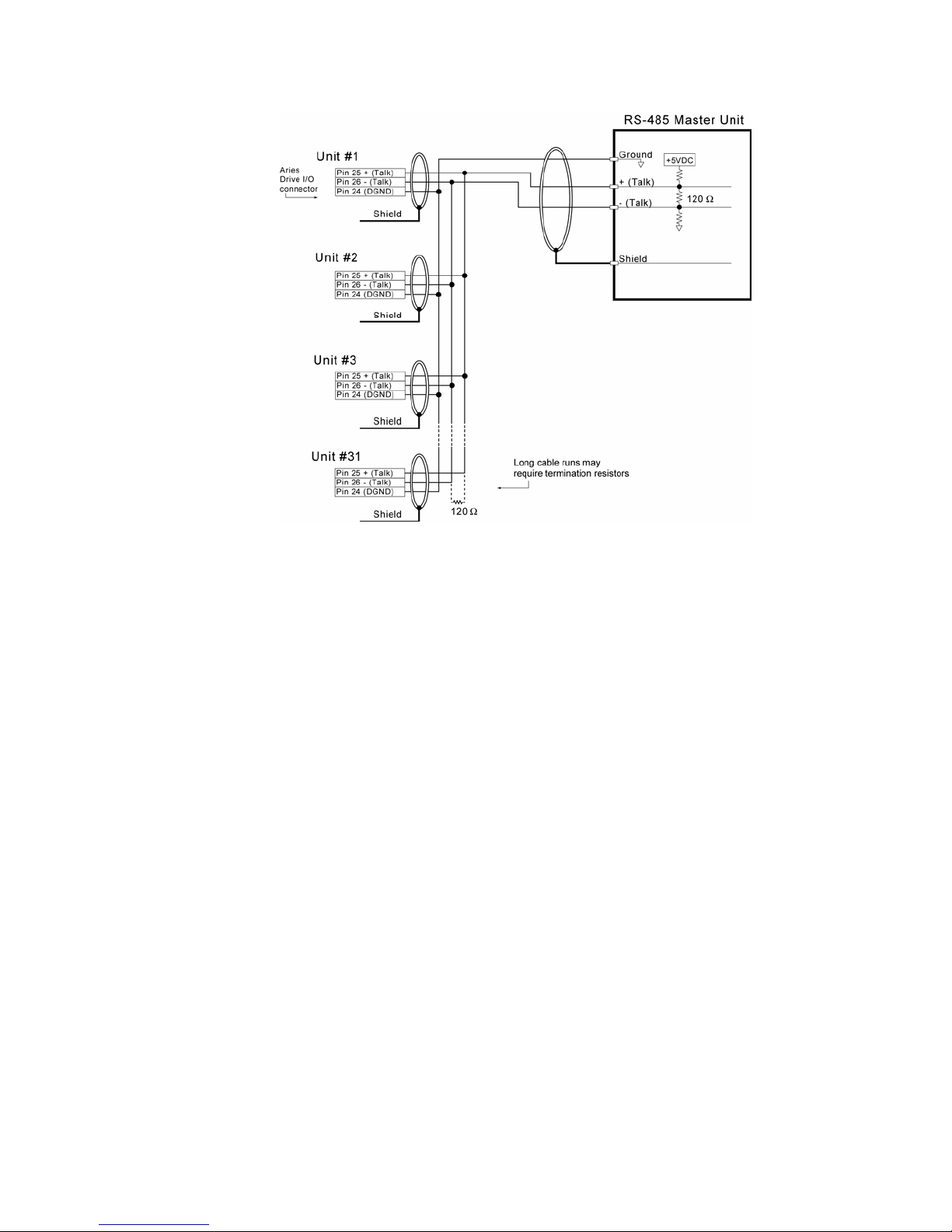
Parker Hannifin
Figure 36 RS-485 Multi-drop Connections
RS-485 Multi-Drop
RS-485 multi-drop lets you connect up to 99 Aries drives together (see
Figure 36). Every drive is factory configured
Using the ADDR command, you can assign a unique address to each drive.
You must address each drive individually before connecting it to the multidrop network.
Notes
• For RS-485 to work correctly turn off the echo mode (ECHOØ).
• Zero (0) is not a valid address for a drive.
Setting up Drives for a Multi-Drop Network
1. Connect the drive you want to configure to a PC that is not part of the
multi-drop network.
2. Apply power to the drive.
3. Using terminal emulation software, send the following command—
Ø_ADDRi (where i is the address you want to assign the new unit).
4. Remove power to the drive. The drive can now be installed in the
network.
5. After installing and connecting the drives to the multi-drop network, test
each drive—use safe methods suitable for your particular application—
to ensure each functions correctly.
To test each unit, send the i_TREV command, where i represents the
address of a drive.
with a default address—zero (0).
76 Aries User Guide
Page 77
Parker Hannifin
Warning — Risk of damage and/or personal injury When testing the
installation of drives, use safe methods suitable for your particular
application.
Replacing a Unit in the Network
If you need to replace a drive, do the following:
1. Remove the old unit from the network.
2. Connect the new drive to a PC that is not part of the multi-drop network.
3. Apply power to the drive.
4. Using terminal emulation software, send the following command—
Ø_ADDRi (where i is the address you want to assign the new unit).
5. If you can communicate with the old drive, upload its configuration using
the Aries Support Tool. Alternatively, you can create a new configuration
file using the Aries Support Tool. Then download the configuration file to
the new drive.
6. Remove power to the drive. The drive can now be installed in the multidrop network.
Sending Commands to a Specific Unit
You can send ASCII commands from the master unit (for example a personal
computer, PLC, or controller) to a specific unit in the multi-drop network.
Prefix the command with the unit address and an underscore (_). For
example, 3_ERES4ØØØ sets the encoder resolution to 4000 for unit 3. The
master unit can receive data from any unit in the network.
Note: Make sure you can access each unit on the network. See “Setting up
s for a Multi-Drop Network” on page 76.
Drive
RS-232/485 Dongle for Communications Setup
The Aries Dongle is a Y-cable (part number 71-021609-01) that breaks out
the RS-232/485 portion of the
communicate with the Aries Drive while it is also connected with a motion
controller.
Note: When using the Aries Dongle, you must use a null-modem (cross-
over) cable between your PC and the Aries drive
Caution — The dongle is designed for setup and troubleshooting purposes
only. Do not use the dongle in a permanent installation; it does not meet
EMC requirements.
DRIVE I/O cable so that you may simultaneously
Chapter 4 Communications 77
Page 78

Chapter 5 Tuning
CHAPTER FIVE
Tuning
Servo Tuning Overview .............................................................................79
Position Variable Overview
Servo Response Overview
Servo System Gains ..................................................................................83
Servo Tuning Example
IN THIS CHAPTER
........................................................................ 80
........................................................................81
..............................................................................86
Page 79
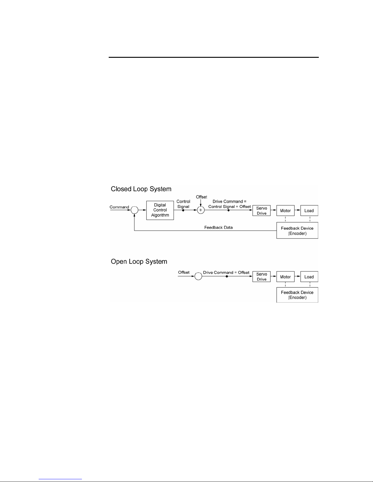
Parker Hannifin
Servo Tuning Overview
The drive uses a digital control algorithm to control and maintain the position
and velocity. The digital control algorithm consists of a set of numerical
equations used to periodically (once every servo sampling period) calculate
the value of the control output.
The numerical terms of the equations consist of the current commanded and
actual position values (including a few from the previous sampling period),
and a set of control parameters. Each control parameter, commonly called a
gain, has a specific function (for more information, see “Servo System Gains”
on pag
gains to achieve optimal servo performance.
When using the control algorithm described above, the whole servo system
acts as a closed-loop system (see Figure 37). It is called closed loop
becau
velocity, tension, etc.) and the feedback data from the encoder. Therefore, it
forms a closed loop of information. When all gains are set to zero, the digital
control algorithm is disabled.
e 83). In
se the control algorithm accounts for both the command (position,
addition, tuning is the process of selecting and adjusting
Figure 37 Closed Loop and Open Loop System Comparison
To command a drive, controllers can provide ±10V analog output or step and
direction signals. Once the digital control algorithm has calculated the digital
control signal, the resultant digital value is sent out from the DSP (digital
signal processor) to the DAC (Digital-to-Analog Converter). The DAC has an
analog output range of -10V to +10V.
It is possible for the digital control signal, calculated by the control algorithm,
to exceed the DACs output range. If this occurs, the resulting analog output
becomes saturated—where the analog output signal remains at the limit until
the position error changes such that the control algorithm calculates a control
signal less than the limit.
The phenomenon of reaching the output limit is called controller output
saturation. When saturation occurs, increasing the gains does not help
improve performance because the DAC is already operating at its maximum
level.
Chapter 5 Tuning 79
Page 80
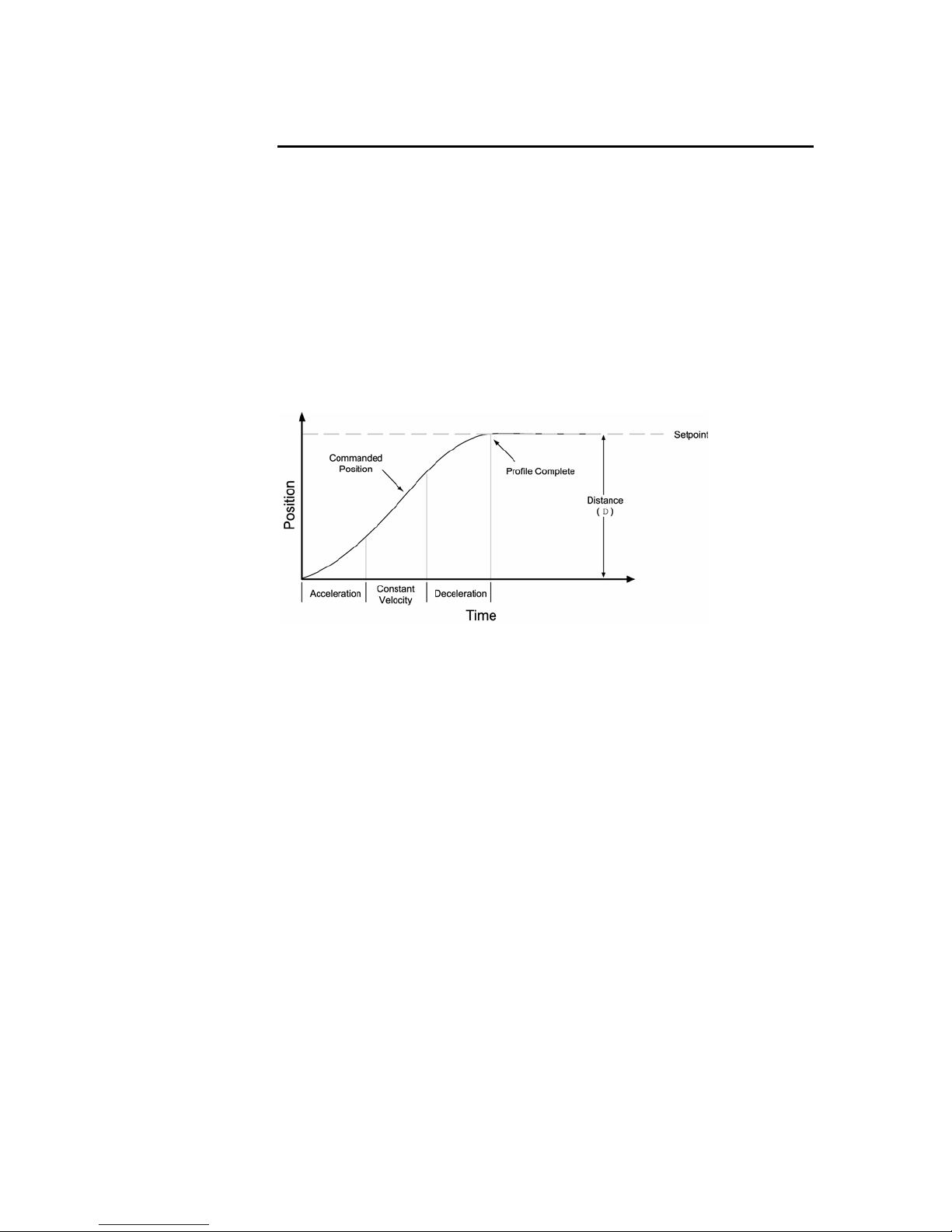
Parker Hannifin
Position Variable Overview
In a servo system, the controller uses two types of position information:
commanded position and actual position. As these positions change with
time, you can use the position values to determine if the system is positioning
as you expect.
Commanded Position
The commanded position is calculated by the motion profile routine from the
controller and it is updated every servo sampling period. Therefore, the
commanded position is the intended position at any given point of time.
To view the commanded position, use the TPC (Transfer Commanded
Position) command; the response represents the commanded position at the
instant the command is received.
Figure 38 Commanded Position
Actual Position
The actual position of the motor/load is the drive’s response to the
commanded position, and is measured with the feedback device. The profile
resulting from the actual position across time is the position response (for
more information, see “Servo Response Overview” on page 81).
To view the a
command; the response represents the actual position at the instant the
command is received.
The difference between commanded and actual positions is called position
error. To view the position error, use the TPER (Transfer Position Error)
command; the response represents the position error at the instant the
command is received.
If the motor is not moving, the position error is called a steady-state position
error. If a position error occurs when the motor is moving, it is called a
position tracking error.
Even when the system is properly tuned, the position error can still be quite
significant due to a combination of factors such as the desired profile, the
motor's limitation, the dynamic characteristics of the system, etc. For
example, if the commanded velocity is higher than the maximum velocity the
motor can physically achieve, the actual position will always lag behind the
ctual position, use the TPE (Transfer Position of Encoder)
80 Aries User Guide
Page 81
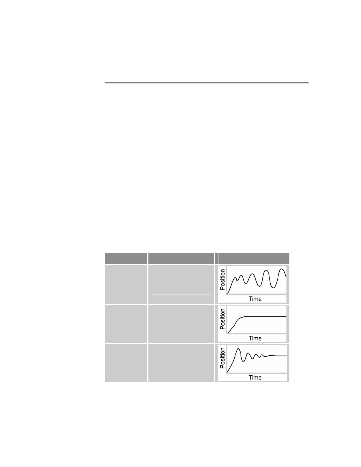
Parker Hannifin
commanded position. Under these circumstances, a position error will
accumulate no matter how high the gains are set.
Servo Response Overview
Stability
The first objective of tuning is to stabilize the system. The formal definition of
system stability is when a bounded input is introduced to the system, the
output of the system is also bounded. What this means to a motion control
system is if the system is stable, and the position setpoint is a finite value,
the final actual position of the system is also a finite value.
In contrast, if the system is unstable, no matter how small the position
setpoint or how little a disturbance (motor torque variation, load change,
noise from the feedback device, etc.) the system receives, the position error
will increase exponentially in almost all cases. In practice, when the system
experiences instability, the actual position will oscillate in an exponentially
diverging fashion as shown in Table 38.
One commo
is unstable. It is important to recognize that a system is considered stable if
the oscillation finally diminishes (damps out), even if it takes a long time.
n misperception is that whenever there is oscillation, the system
Position Response Types
Table 38 identifies the six basic types of position responses. The primary
difference among these responses is due to damping—the suppression (or
cancellation) of oscillation.
Response Description Profile (position/time)
Unstable
Overdamped
Underdamped
Instability causes the
position to oscillate in
an exponentially
diverging fashion.
A highly damped, or
over-damped, system
gives a smooth but
slower response.
A slightly damped, or
under-damped,
system gives a slightly
oscillatory response.
Chapter 5 Tuning 81
Page 82
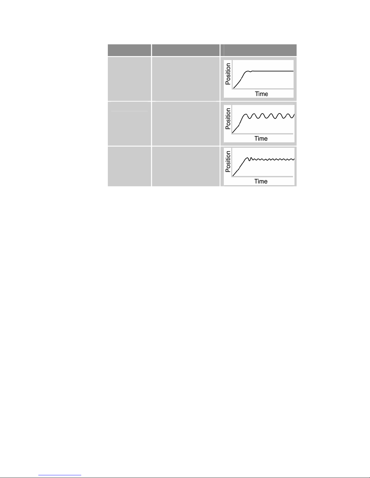
Parker Hannifin
Response Description Profile (position/time)
Critically
damped
A critically-damped
response is the most
desirable because it
optimizes the trade-off
between damping and
speed of response.
Oscillatory
An oscillatory
response is
characterized by a
sustained position
oscillation of equal
amplitude.
Chattering
Chattering is a highfrequency, lowamplitude oscillation
that is usually audible.
Table 38 Position Response Types
Performance Measurements
If you plot of the position response versus time, you can make a few
measurements to quantitatively assess the performance of the servo. These
three measurements are made before or shortly after the motor stops
moving:
• Overshoot—The measurement of the maximum magnitude that the
actual position exceeds the position setpoint. It is usually measured
in terms of the percentage of the setpoint value.
• Rise Time—The time it takes the actual position to pass the
setpoint.
• Settling Time—The time between when the commanded position
reaches the setpoint and the actual position settles within a certain
percentage of the position setpoint. (Note the settling time definition
here is different from that of a control engineering text book, but the
goal of the performance measurement is still intact.).
82 Aries User Guide
Page 83

Parker Hannifin
Servo System Gains
Proportional Feedback Control (SGP)
Proportional feedback is the most important feedback for stabilizing a servo
system. When the controller uses proportional feedback, the control signal is
linearly proportional to the position error (the difference between the
commanded position and the actual position—see TPER command). The
proportional gain is set by the Servo Gain Proportional (SGP) command.
Proportional feedback can be used to make the servo system more
responsive (stiff), as well as reduce the steady state position error.
Because the control is proportional to the position error, whenever there is
any disturbance (such as torque ripple or a spring load) forcing the load away
from its commanded position, the proportional control can immediately output
a signal to move it back toward the commanded position. This function is
called disturbance rejection.
If you tune your system using only the proportional feedback, increasing the
proportional feedback gain (SGP value) too much will cause the system
response to be oscillatory, under-damped, or in some cases unstable.
Note: Do not set the proportional feedback gain (SGP) to zero, except when
open-loop operation is desired.
Velocity Feedback Control (SGV)
Using velocity feedback control, the control signal is proportional to the
feedback device's velocity (rate of change of the actual position). The Servo
Gain Velocity (SGV) command sets the gain, which is in turn multiplied by the
feedback device's velocity to produce the control signal. Because the velocity
feedback acts upon the feedback device's velocity, its control action
essentially anticipates the position error and corrects it before it becomes too
large. Such control tends to increase damping and improve the stability of the
system.
A high velocity feedback gain (SGV) can also increase the position tracking
error when traveling at constant velocity. In addition, setting the velocity
feedback gain too high tends to slow down (over-damp) the response to a
commanded position change.
Integral Feedback Control (SGI)
Using integral feedback control, the value of the control signal is integrated at
a rate proportional to the feedback device position error. The rate of
integration is set by the Servo Gain Integral (SGI) command.
The primary function of the integral control is to overcome friction and/or
gravity and to reject disturbances so that steady state position error is
minimized or eliminated. This control action is important for achieving high
system accuracy. However, if you can achieve acceptable position accuracy
by using only the proportional feedback (SGP), then there is no need to use
the integral feedback control.
Chapter 5 Tuning 83
Page 84
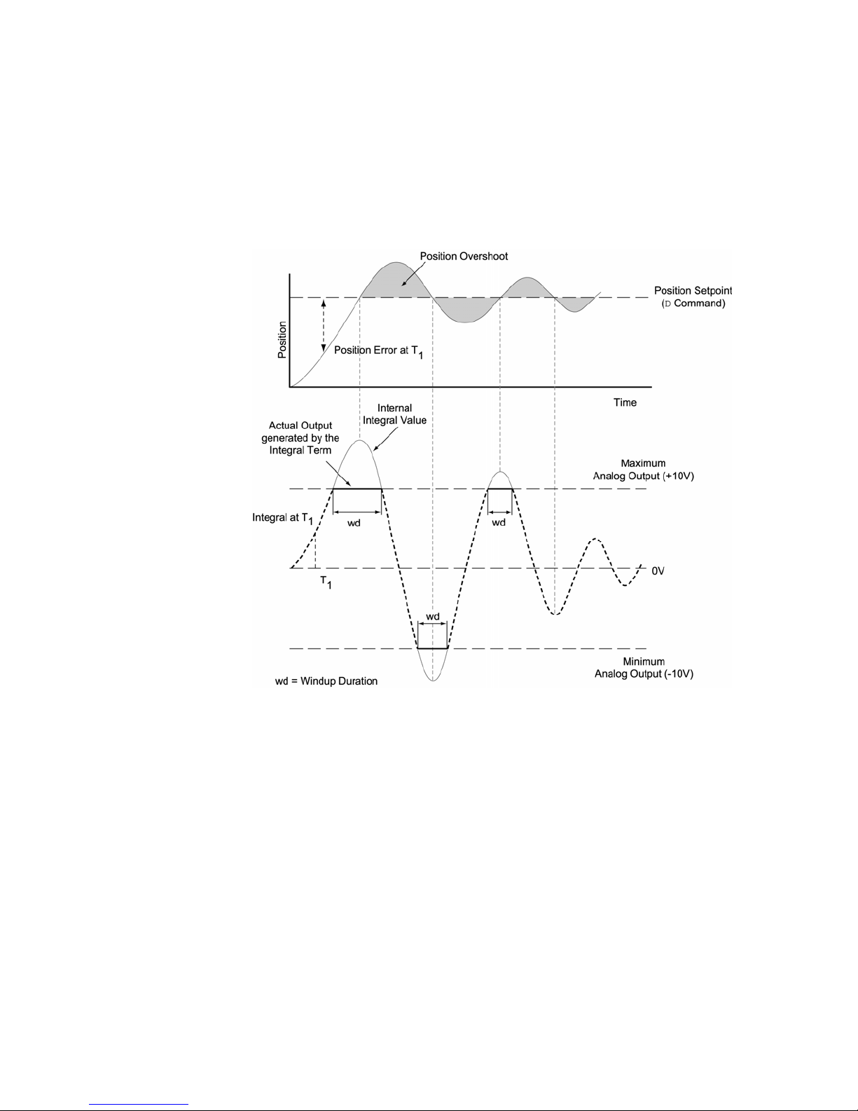
Parker Hannifin
Controlling Integral Windup
If you are using integral control (SGI) and there is an appreciable position
error that persists long enough during the transient period (time taken to
reach the setpoint), the control signal generated by the integral action can
end up too high; this saturates to the maximum level of the controller's
analog control signal output. This phenomenon is called integrator windup
(see Figure 39).
84 Aries User Guide
Figure 39 Integrator Windup (Without Using SGILIM Command)
After windup occurs, it takes time before the integrator output returns to a
level within the limit of the controller's output. Such a delay causes excessive
position overshoot and oscillation.
The integral windup limit (SGILIM) command allows you to set the absolute
limit of the integral. The commanded limit, in essence, turns off the integral
action as soon as it reaches the limit; consequently, position overshoot and
oscillation can be reduced (see Figure 40).
Page 85
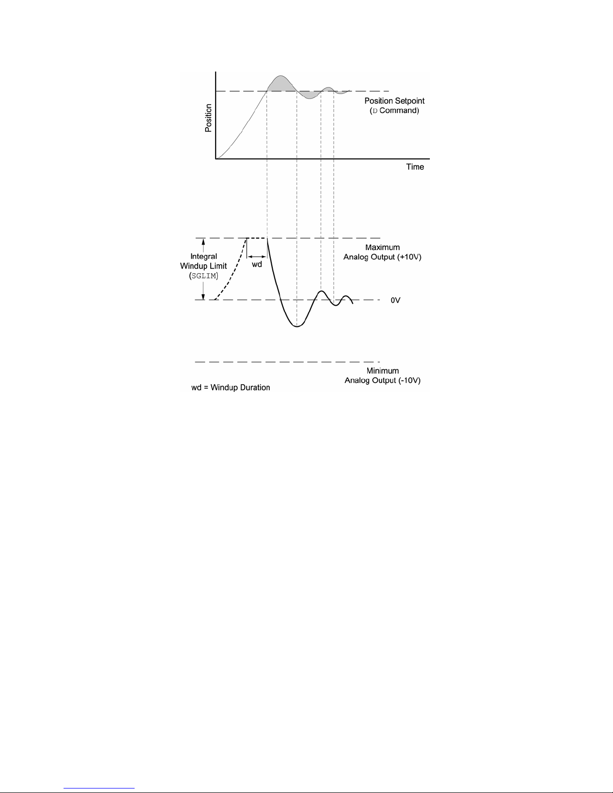
Parker Hannifin
Figure 40 Integrator Windup (using the SGILIM Command)
Chapter 5 Tuning 85
Page 86
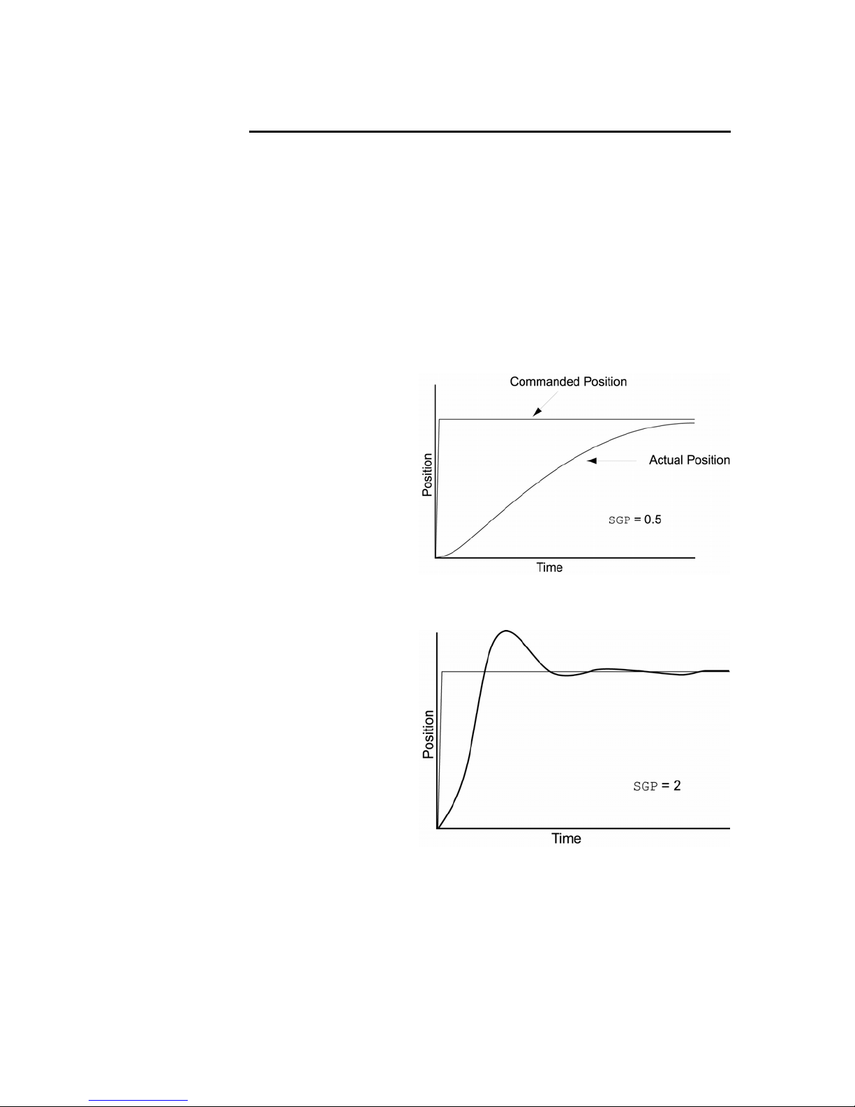
Parker Hannifin
Servo Tuning Example
The example below illustrates how to experimentally obtain the highest
possible proportional feedback (SGP) an
a Servo Tuning flow diagram, see “Appendix A Additional Specifications” on
page 168.
d velocity feedback (SGV) gains. For
The motion
size of 200. The plots shown are as they appear in the Aries Support Tool
(X axis = time, Y axis = position).
Note: The steps shown below (steps 1 to 11) represent the major steps of
the process; the actual progression between these steps may require several
iterations.
command used for this example is a step command with a step
Step 1
For a starting trial, we set
the proportional feedback
gain (SGP) to .5. As
can see by the plot, the
response is slow.
In the next step, we should
increase SGP until
response is slightly under
damped.
you
the
Step 2
With SGP equal to 2, the
response becomes slightly
under damped (see plot).
Therefore, we should
introduce the velocity
feedback gain (SGV) to
damp out the
oscillation.
86 Aries User Guide
Page 87
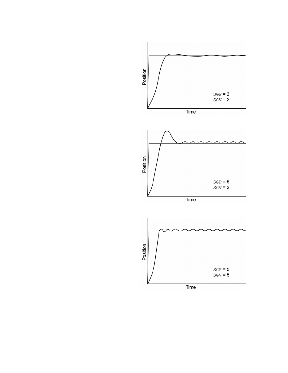
Step 3
Step 3
With SGV equ
response is fairly well
damped (see plot).
At this point, the SGP
uld be raised again
sho
until oscillation or
excessive overshoot
appears.
al to 2, the
Step 4
As we iteratively increase
SGP to 5, ove
chattering becomes
significant (see plot). This
means the SGV gain is to
low and/or the SGP is
high.
Next, we should try raising
the SGV gain to see if it will
dampe
and chattering.
rshoot and
too
n out the overshoot
Parker Hannifin
o
Step 5
After the SGV gain is
raised to 5, the overshoot
was reduced but
chattering is still quite
pronounced. This means
either one or both of the
gains is too high.
The next step should be to
lower the SGV gain firs
t.
Chapter 5 Tuning 87
Page 88
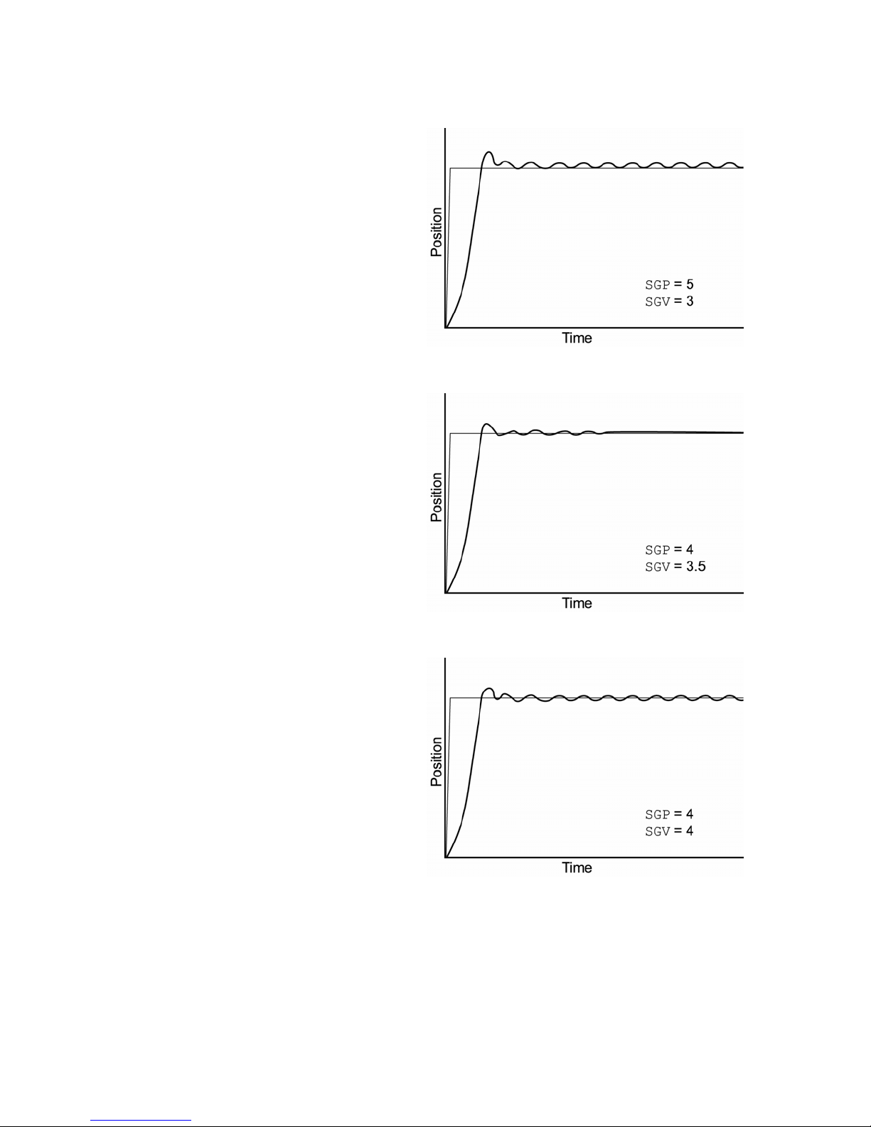
Step 6
Lowering the SGV gain to 3
does not help reduce the
chattering by much.
Therefore, we should
lower the SGP gain until
chatteri
ng stops.
Step 7
Chattering stops after
reducing the SGP gain to 4
wever, the overshoot is
Ho
still a little too high.
The next step should be to
try raising the SGV to
damp out the
overshoot.
Parker Hannifin
Step 8
After raising the SGV gain
to 4, overshoot is reduced
a little, but chattering
reappears. This means the
gains are still too high.
Next, we should lower the
SGV gain until
stops.
chattering
88 Aries User Guide
Page 89
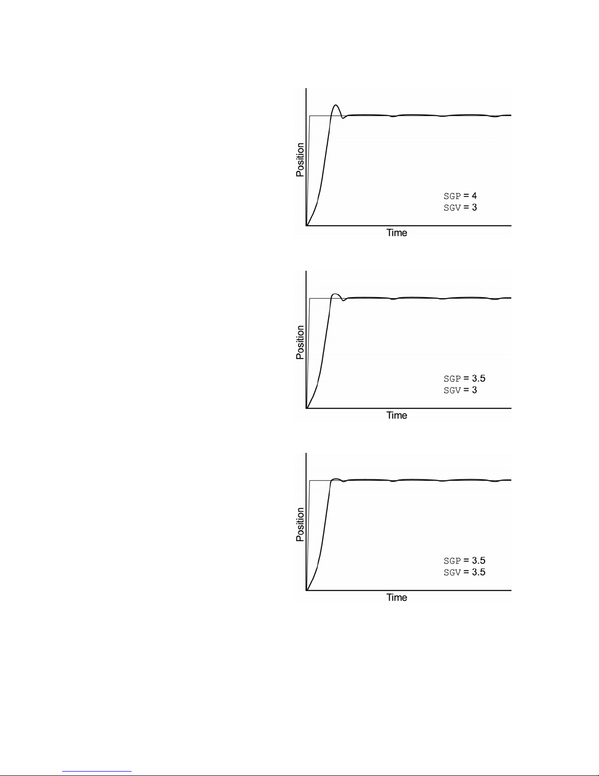
Step 9
After lowering the SGV
gain to 3 (even less than in
Step 7—3.5), chattering
stops.
Next we should lower the
SGP gain.
Step 10
Overshoot is reduced very
little after lowering the SGP
gain to 3.5. (The SGV gain
might have b
too much in Step 9.)
Next, we should try raising
the SGV gain again u
the overshoot is gone.
een lowered
ntil
Parker Hannifin
Step 11
When we raised the SGV
gain to 3.5, the step
respon
very stable.
se became fast and
Chapter 5 Tuning 89
Page 90

Parker Hannifin
Auto-Tuning
The Aries drive can automatically determine the inertia of the load attached
to the motor. This is performed by applying a specified torque to the motor
and measuring the acceleration and deceleration of the motor. From this, the
Aries drive can calculate the load inertia and store the value in the LJRAT
command.
Note: Excess friction can affect the measured inertia, thereby estimating the
value higher than the actual inertia. While the drive can compensate for
some friction, it may not compensate for all. If the estimated load inertia
seems overly high, this may be the cause.
Note: Use this method of auto-tuning only with the step and direction
versions of the Aries drive.
The Auto-Tune process should only last a few seconds, during which time
the motor will rotate about one-quarter of a turn in each direction. Following
are the two methods to start Auto-Tune mode.
► In the Aries Support Tool, select the Servo Tuner tab. Then click
Auto-Tune.
—or—
► Put the drive in position mode (DMODE6 or 7). On the drive’s ±10V
Analog Input, apply a command voltage greater than 3V, then reset the
drive.
To return to normal operation, remove the command voltage and reset
the drive.
90 Aries User Guide
Page 91

Chapter 6 Command Reference
CHAPTER SIX
Command
Reference
IN THIS CHAPTER
Description of Format ................................................................................92
Syntax – Letters and Symbols
Syntax – General Gui
Command Descriptions
delines..................................................................... 94
...................................................................92
.............................................................................95
Page 92
Parker Hannifin
Aries Communications Set-up
Before you can communicate with the Aries drive, you must configure your
terminal emulator. You can use HyperTerminal or an equivalent terminal
emulator. For information about setting up communications, see “RS-232/485
unications” on page 71.
Comm
Description of Format
1. 2. 3.
ERES
4. Type
5. Syntax
6. Units
7. Range
8. Default
9. Response
10. See Also
Encoder Resolution
Encoder Configuration
<a_>ERES<i>
Rotary motor: i = counts/revolution
Linear motor: i = counts/electrical pitch
2ØØ to 1Ø73741823
4ØØØ
ERES: <*>4ØØØ
DMEPIT, DMTR, TPE
Product Rev
Aries 1.0
Number Description
1. Mnemonic Code: This field contains the command's mnemonic code.
2. Full Name: This field contains the command's full name.
3. Valid Product & Revision: This field lists the Aries Series products and the revision of
4. Type: This field contains the command’s type.
5. Syntax: The proper syntax for the command is shown here. The specific parameters
6.
7. Range: The range of valid values that you can specify for an argument (or any other
8. Default: The default setting for the command is shown in this field. A command will
9. Response: Some commands allow you to check the status of the command. In the
10. See Also: Commands related or similar to the command described are listed here.
each product when this command was incorporated or modified per the description. If
the command does not apply to that particular product, the Revision is specified as
“N/A”. All commands applicable to the standard product versions are applicable to the
OEM versions unless otherwise noted (e.g., 6250 commands are applicable to the
OEM6250 controller).
You can use the TREV command to determine which product revision you are using.
For example, if the TREV response is Aries Revision 1.0, The product revision is 1.0
associated with the command are also shown. Definitions of the parameters are
described in the Syntax sections below.
Units: This field describes what unit of measurement the parameter (b, d, i, r, or t) in
the command syntax represents.
parameter specified).
perform its function with the default setting if you do not provide a value.
example above, entering the ERES command by itself, you will receive the response
<*>4ØØØ. The <*> only appears for RS-485 communication, and does not appear for
RS-232 communication.
Table 39 Commands-Description of Format
92 Aries User Guide
Page 93
ERES
Type
Syntax
→
Units
Range
Default
Response
Parker Hannifin
Syntax – Letters and Symbols
The command descriptions provided within this manual use alphabetic letters
and ASCII symbols within the Syntax description (see example below) to
represent different parameter requirements.
Encoder Resolution
Encoder Configuration
<a_>ERES<i>
Rotary motor: i = counts/revolution
Linear motor: i = counts/electrical pitch
2ØØ to 1Ø73741823
4ØØØ
ERES: <*>4ØØØ
Symbol Description
a_
b
c
d
i
r
t
,
< >
* The ASCII character b can also be used within a command to precede a binary number.
When the b is used in this context, it is not to be replaced with a Ø or 1. For example,
comparisons such as ERROR= b1x1.
Represents an address specifier, numeric value from Ø to 99. An address
specifier is required if multiple Aries drives are connected in a daisy-chain or
multi-drop configuration; in fact, leaving off the address specifier will cause
parameter assignment commands to affect all units and response/transfer
commands to request information from all units at the same time (multiple
units transmitting characters at one time will garble the communication). To
assign unique unit addresses to multiple drives, refer to the ADDR command.
Represents the values 1 or Ø; does not require field separator between
values. *
Represents a character (A to Z, or a to z)
Represents the values 1 or Ø, E or e; does not require field separator between
values. E or e enables a specific command field.
Represents a numeric value that cannot contain a decimal point (integer
values only). The numeric range varies by command. Field separator
required.
Represents a numeric value that may contain a decimal point, but is not
required to have a decimal point. The numeric range varies by command.
Field separator required.
Represents a string of alphanumeric characters from 1 to 16 characters in
length. The string must start with an alpha character.
(Comma) Represents a field separator. Commands with the symbol r or i in
their Syntax description require field separators.
Commands with the symbol b or d in their Syntax description do not require
field separators (but they may be included). See Table 41.
Indicates that the item contained within the < > is optional, and not required
by that command.
Note: Do not confuse with <cr>, <sp>, and <lf>, which refer to the ASCII
characters corresponding to a carriage return, space, and line feed,
respectively.
Product Rev
Aries 1.0
Table 40 Commands-Syntax
Chapter 6 Command Reference 93
Page 94
Parker Hannifin
Syntax – General Guidelines
Guideline Topic Guideline Examples
Command Delimiters
(<cr> and <lf>)
Neutral Characters
(<sp>)
Case Sensitivity There is no case sensitivity. Use
Comment Delimiter
[semi-colon ( ; ) or
apostrophe ( ‘ )]
Binary and
Hexadecimal Values
Note: The command line is limited to 32 characters (including spaces).
All commands must be separated
by a delimiter. A carriage return is
the most commonly used.
Using neutral characters
anywhere within a command will
not affect the command.
upper or lower case letters within
commands.
All text between a comment
delimiter and a command delimiter
is considered program comments.
When making assignments with or
comparisons against binary or
hexadecimal values, you must
precede the binary value with the
letter “b” or “B”, and the hex value
with “h” or “H”. In the binary
syntax, an “x” simply means the
status of that bit is ignored.
Set velocity limit to 100 rps:
DMVLIM<sp>1ØØ<cr>
Initiate motion:
GO1
go1
Add a comment to the command:
DMVLIM<sp> ; set
velocity
; limit
Binary:
ERRORL = bØ1111x11111111111
Hexadecimal:
ERRORL = h7FxF
Table 41 Syntax Guidelines
94 Aries User Guide
Page 95

ADDR
Type
Syntax
Units
Range
Default
Response
See Also
Parker Hannifin
Command Descriptions
You can use the ASCII commands, provided in this chapter, to configure,
check errors, and reset the Aries drive through a terminal emulator. A
terminal emulator, however, is not required, Instead, you can use the Aries
Supp0ort Tool software to perform the same operations.
Note: The Aries Support Tool does not support the CMDDIR and ADDR
commands. You must use a terminal emulator to set the commanded
direction and address of each drive.
Before you can communicate with the Aries Drive, you must configure your
terminal emulator. You can use HyperTerminal or an equivalent terminal
emulator, For more information about setting up communications, see “RS232/48
Multiple Unit Address
Drive Configuration
<a_>ADDR<i>
i = unit number
Ø to 255
Ø
ADDR: <*>Ø
none
The ADDR command configures the unit address for an RS-485 multi-drop
network. The factory default address for an Aries drive is zero (0). The ADDR
command allows you to uniquely address up to 255 units (99 unit maximum
on a single network).
5 Communications” on page 74
Product Rev
Aries 1.0
After establishing a unique address for each Aries drive, you can address
commands to specific units. To do this, prefix the command with the unit’s
address followed by an underscore ( _ ). For example, 2_ERES reports the
resolution on unit 2.
RS-485 Multi-Drop
You must address each unit before adding it to the multi-drop network.
For example, you want to set up a 4-unit multi-drop network, where the
drives are addressed as units 1 through 4. After addressing a drive, you
can install it in the multi-drop network.
1. Connect the drive to become unit 1. Through a terminal emulator,
send the following command: Ø_ADDR1
2. Connect the drive to become unit 2. Through a terminal emulator,
send the following command: Ø_ADDR2
3. Connect the drive to become unit 3. Through a terminal emulator,
send the following command: Ø_ADDR3
4. Connect the drive to become unit 4. Through a terminal emulator,
send the following command: Ø_ADDR4
If you need to replace a unit in the multi-drop network, connect to the
individual device and send the Ø_ADDRi command, where “i”
Chapter 6 Command Reference 95
Page 96

ALIGN
Type
Syntax
Units
Range
Default
Response
See Also
Parker Hannifin
represents the address of the new unit. Then connect the drive to the
network.
Note: All command responses on an RS-485 network are preceded by <*>.
Align encoder
Drive configuration
<a_>ALIGN
N/A
N/A
0
none
DMODE, DRIVE, ENCOFF, ENCPOL, P163, SHALL
Product Rev
Aries 1.0
The ALIGN command aligns the encoder on the motor so that the drive can
commutate the motor correctly. This command is especially useful for
configuring a custom motor. To align the motor, use the following procedure:
1. Remove any load from the shaft. The procedure works best with an
unloaded motor.
2. Disable the drive by means of the hardware enable or by typing DRIVE0
into the terminal and pressing Enter.
3. Type DMODE3 in the terminal and press Enter to enter alignment mode.
4. Enable the drive by means of either the hardware enable or by typing
DRIVE1 into the terminal and press Enter.
5. Type ALIGN into the terminal and press Enter to begin the alignment
process.
6. The drive then begins the alignment procedure. This could take up to 20
seconds.
Note: The motor turns up to 90 degrees during this procedure.
96 Aries User Guide
7. The alignment process may modify the following parameters:
ENCOFF, ENCPOL, SHALL, CMDDIR, P163
These parameters are stored in the drive. If you want to store them in a
smart encoder, type the ESTORE command into the terminal and press
Enter. It takes a couple of seconds to store the motor data in the motor.
Page 97

ANICDB
(
D
A
− =
D
−
(
+
=
()(
+≤≤
(
D
A
+ =
D
−
(
<
(
D
D
− =
l
A
−
(
+
=
()(
+≤≤
(
D
D
−
=
A
+
(
<
Type
Syntax
Units
Range
Default
Response
See Also
Parker Hannifin
Analog Input Center Deadband
Drive Configuration
<a_>ANICDB<r>
r = volts
Ø.ØØ to 1Ø.ØØ
Ø.Ø4
ANICDB: *ANICDBØ.Ø4
DCMDZ, DMTSCL, TANI
The ANICDB allows the user to specify the voltage deadband for the
command input. ANICDB is used with DCMDZ to configure the command input
for DMODE2 and DMODE4. The commanded torque, Trq
from the input voltage, V
Trq
command
V
when
in
, using DMTSCL as follows:
in
CMDZ
V
in
>
NICDB
ANICDBDCMDZ
MTSCL
)
)
Product Rev
Aries 2.0
, is calculated
command
10
Trq
command
when
Trq
command
when
The commanded velocity, Vel
using DMVSCL as follows:
Ve
command
when
Vel
command
when
Vel
command
when
0
V
in
V
in
V
V
in
CMDZ
in
>
0
CMDZ
V
in
V
in
ANICDBDCMDZANICDB-DCMDZ
MTSCL
CMDZ
V
in
NICDB
)
10
ANICDB-DCMDZ
, is calculated from the input voltage, V
command
ANICDBDCMDZ
)
NICDB
MVSCL
)
10
)
V
in
NICDB
MVSCL
)
ANICDBDCMDZANICDB-DCMDZ
10
ANICDB-DCMDZ
)
)
,
in
)
Chapter 6 Command Reference 97
Page 98

CERRLG
Type
Syntax
Units
Range
Default
Response
See Also
Parker Hannifin
Clear the Error Log
Error Handling
<a_>CERRLG
N/A
N/A
N/A
N/A
CONFIG, ERRORL, ERROR, TANI, TDHRS, TDMIN,
Product Rev
Aries 1.0
TDSEC, TDTEMP, TERRLG, TMTEMP, TVBUS
The CERRLG command erases the stored contents of the error log. Clearing
the error log is a helpful diagnostic tool; it allows you to start the diagnostic
process when the error log is in a known state so that you can check the
error log in response to subsequent events.
The error log is updated every time an error occurs. The TERRLG command
displays the last ten error conditions that the drive has experienced, as
recorded in these status registers:
• TANI (current command input voltage)
CMDDIR
Type
Syntax
Units
Range
Default
Response
See Also
• CONFIG (text-based status report of configuration errors)
• ERROR (list of error messages)
• TDHRS (number of hours since the drive was powered up or RESET)
• TDTEMP (measured temperature of the drive in centigrade)
• TMTEMP (estimated temperature of the motor in centigrade)
• TVBUS (measured bus voltage in volts)
Direction of Rotation
Drive Configuration
<a_>CMDDIR<b>
b = enable bit
Ø (CW rotation for positive analog input) or
1 (CCW rotation for positive analog input)
Ø
CMDDIR <*>Ø
ANICDB, DCMDZ, DMTSCL, DRES, ENCPOL, IANI,
Product Rev
Aries 1.0
TANI
The CMDDIR command determines the direction of shaft rotation (or direction
of travel for linear motors) for positive analog input. The default is clockwise
shaft rotation for a positive command.
Sending a CMDDIR1 command changes the direction to counter clockwise.
In addition, the encoder counts positive for counter clockwise rotation with
CMDDIR1.
Note: This command does not take effect until you cycle power to the drive,
or send the RESET comm
98 Aries User Guide
and.
Page 99
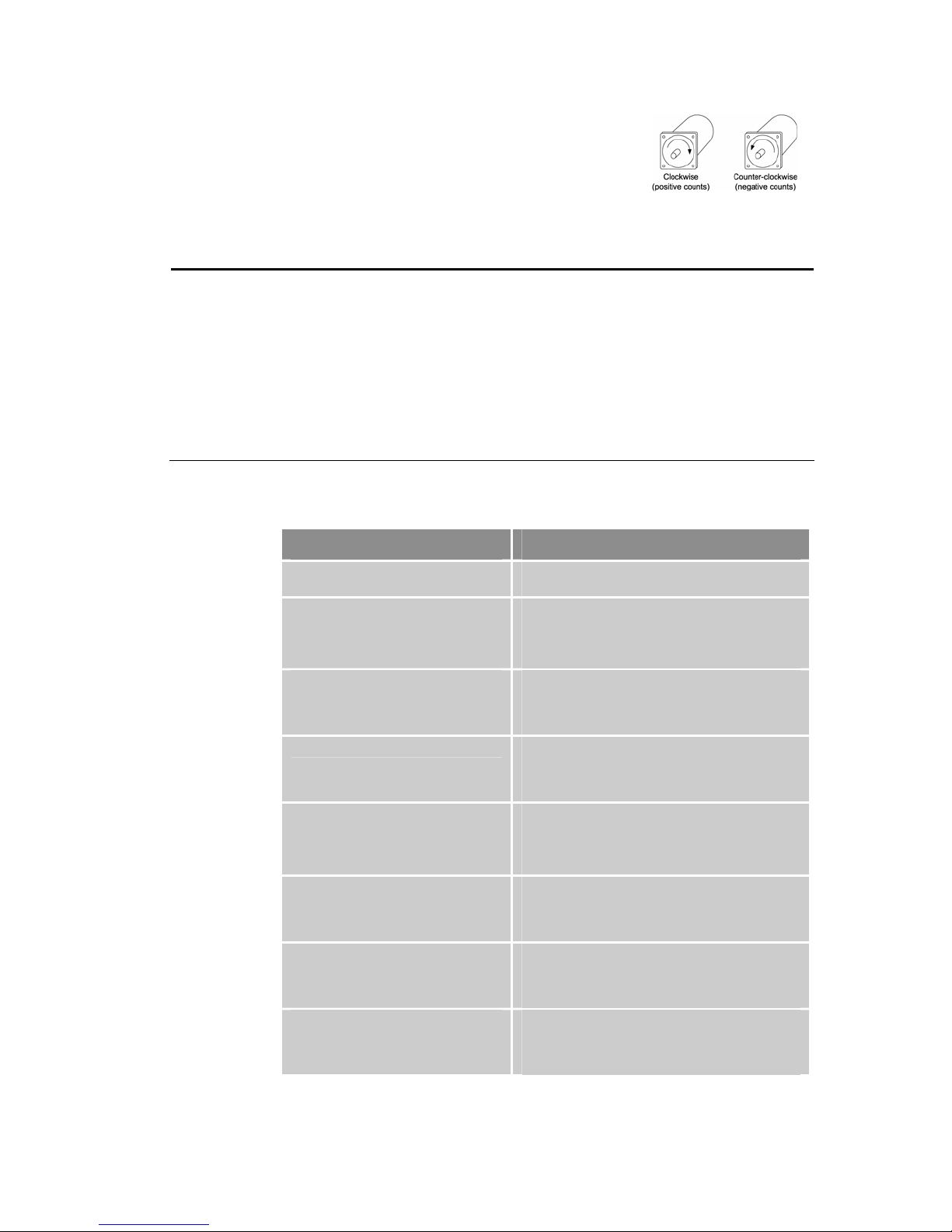
CONFIG
Type
Syntax
Units
Range
Default
Response
See Also
Parker Hannifin
Rotary Motors—Positive values represent
clockwise motion and negative values represent
counter-clockwise motion (assuming CMDDIR = Ø,
and that you connected the feedback device
according to instructions provided in “Chapter 2
anical Installation” and “Chapter 3 Electrical
Mech
tallation”).
Ins
Figure 41 Clockwise/
Counter-clockwise rotation
Configuration Errors and Warnings
Error Handling
<a_>CONFIG
N/A
N/A
N/A
CONFIG <*>No Errors
DMTIC, DMTIND, DMTIP, DMTW, ERROR
Product Rev
Aries 1.0
The CONFIG command gives a text-based status report of current
configuration errors and warnings (EØ through E24).
Error Resolution
EØ—Motor Configuration
Warning
E1—Motor Configuration Error
E3—Max Inductance = Ø
E4—Rated Speed = Ø
E5—DPOLE = Ø
E6—Resistance = Ø
E7—Ke = Ø
E8—Continuous Current = Ø
The motor rating is too high for the drive, and the
drive is using its own limits for safety reasons.
One of the motor parameters is set to zero (0).
Look at the additional errors to find which
parameters are set at zero (0). Refer to your
motor specifications for the correct value.
This parameter is set to zero (0). To correct the
error, you must set a non-zero (0) value. Refer to
your motor specifications for the correct value.
(DMTIND)
This parameter is set to zero (0). To correct the
error, you must set a non-zero value. Refer to
your motor specifications for the correct value.
(DMTW)
This parameter is set to zero (0). To correct the
error, you must set a non-zero value. Refer to
your motor specifications for the correct value.
(DPOLE)
This parameter is set to zero (0). To correct the
error, you must set a non-zero value. Refer to
your motor specifications for the correct value.
(DMTRES)
This parameter is set to zero (0). To correct the
error, you must set a non-zero value. Refer to
your motor specifications for the correct value.
(DMKE)
This parameter is set to zero (0). To correct the
error, you must set a non-zero value. Refer to
your motor specifications for the correct value.
(DMTIC)
Chapter 6 Command Reference 99
Page 100
Parker Hannifin
Error Resolution
E9—Peak Current = Ø
E1Ø—Use Drive Continuous
Current Warning
E11—Torque Rating > Peak
Power Rating Warning
E12— Use Drive Peak Current
Warning
E13 - Inertia = Ø
E14 – Damping = Ø
E15 – Notch filter Calc
Error.
E16 – Lead < Lag Freq
E17 – Lead ≥ 4* Lag Freq
E18 – Lag Freq < 2Ø Hz
E19–E24
This parameter is set to zero (0). To correct the
error, you must set a non-zero value. Refer to
your motor specifications for the correct value.
(DMTIP)
The continuous current of the motor is higher than
the continuous current rating of the drive. Use the
continuous current rating for the drive.
The motor’s torque rating is too high for the power
level of the drive. Use the drive’s torque rating.
The peak current of the motor is higher than the
peak current rating of the drive. Use the drive’s
value for peak current.
This parameter is set to zero (0). The drive will not
enable Velocity or Position Modes. To correct the
error, you must set to a non-zero value. Refer to
your motor specifications for the correct value.
(DMTJ)
This parameter is set to zero (0). The drive will not
enable Velocity or Position Modes. To correct the
error, you must set to a non-zero value. Refer to
your motor specifications for the correct value.
(DMTD)
The notch filter settings caused an internal
calculation error. The last valid value was used.
Try different values for the notch filter parameters.
(DNOTAF, DNOTAQ, DNOTBF, DNOTBQ)
The lead filter setting (DNOTLD) must be greater
than or equal to the lag filter setting. (DNOTLG)
The lead filter setting (DNOTLD) must be less than
or equal to 4 times the lag filter setting. (DNOTLG)
The lag filter setting (DNOTLG) must be greater
than or equal to 20 Hz.
RESERVED
Table 42 Configuration Errors and Warnings
100 Aries User Guide
 Loading...