

Page 1
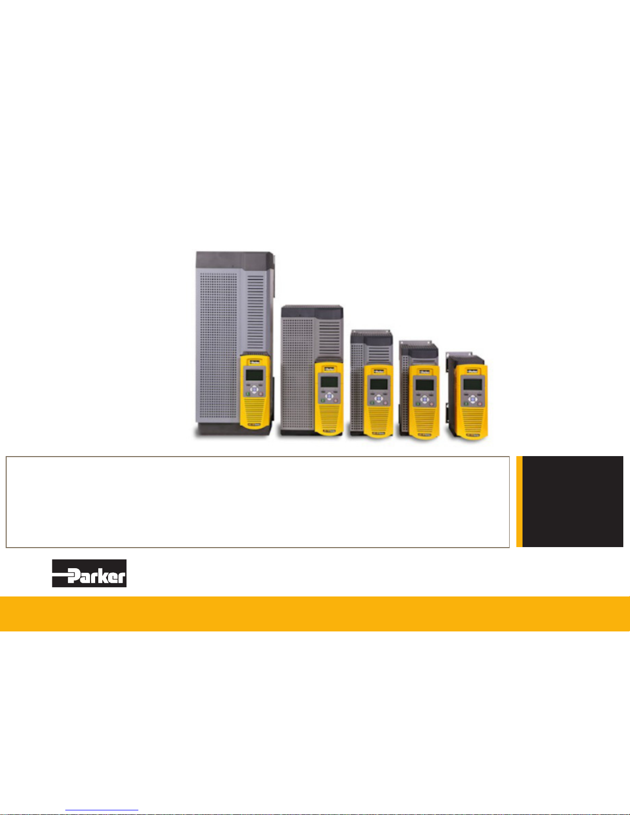
AC30V series
Fan Control Application
HA502134U002 Issue 2
Technical Manual
aerospace
climate control
electromechanical
filtration
fluid & gas handling
hydraulics
pneumatics
process control
sealing & shielding
ENGINEERING YOUR SUCCESS.
www.comoso.com
Page 2

FAILURE OR IMPROPER SELECTION OR IMPROPER USE OF THE PRODUCTS DESCRIBED HEREIN OR RELATED ITEMS
CAN CAUSE DEATH, PERSONAL INJURY AND PROPERTY DAMAGE.
This document and other information from Parker Hannin Corporation, its subsidiaries and authorized distributors provide product or
system options for further investigation by users having technical expertise.
The user, through its own analysis and testing, is solely responsible for making the nal selection of the system and components
and assuring that all performance, endurance, maintenance, safety and warning requirements of the application are met. The user
must analyze all aspects of the application, follow applicable industry standards, and follow the information concerning the product in
the current product catalogue and in any other materials provided from Parker Hannin Corporation or its subsidiaries or authorized
distributors.
To the extent that Parker Hannin Corporation or its subsidiaries or authorized distributors provide component or system options based
upon data or specications provided by the user, the user is responsible for determining that such data and specications are suitable
and sufcient for all applications and reasonably foreseeable uses of the components or systems.
The above disclaimer is being specically brought to the user’s attention and is in addition to and not in substitution to the Exclusions
and Limitations on Liability which are set out in the terms and conditions of sale.
www.comoso.com
Page 3
Fan Control Application
HA502134U002 Issue 2
Copyright 2013 Parker Hannifin Manufacturing Limited
All rights strictly reserved. No part of this document may be stored in a retrieval system, or transmitted in any form or by any means to persons not employed by a Parker Hannifin
Manufacturing Limited company without written permission from Parker Hannifin Manufacturing Ltd. Although every effort has been taken to ensure the accuracy of this document it
may be necessary, without notice, to make amendments or correct omissions. Parker Hannifin Manufacturing Limited cannot accept responsibilit y for damage, injury, or expenses
resulting therefrom.
WARRANTY
Refer to Parker Hannifin Manufacturing Limited Terms and Conditions of Sale. These documents are available on request at www.parker.com.
Parker Hannifin Manufacturing Limited reserves the right to change the content and product specification without notice.
www.comoso.com
Page 4

2 Fan Control Application Manual
AC30V series Variable Speed Drive
Fan Control Application Manual
Description
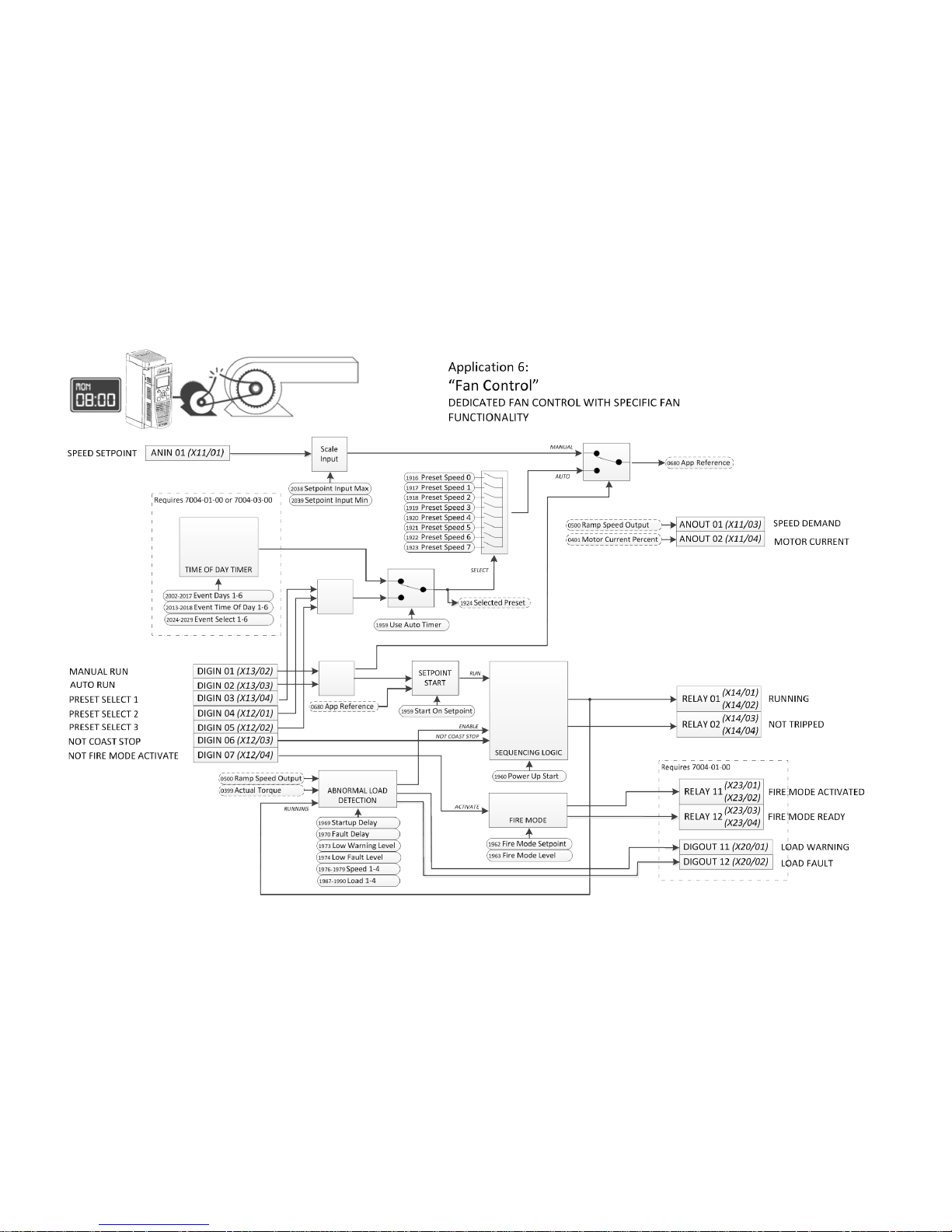
The fan application provides speed control using a speed reference from either an analogue input terminal, a preset speed selected by digital
terminals or, if a Real Time Clock (RTC) option is fitted, a preset speed selected by built-in time of day / day of week programmer.
Features
• Automatic belt breakage detection (abnormal load)
• Timed run function. Start/stop events can be programmed with different running speeds.*
• Skip frequencies to enable resonant points on the fan to be avoided
• Fire Mode. Run to destruction if commanded to do so.
• Preset speeds
• Power-up start
• Auto Start on non-zero setpoint
• Separate Manual Run and Auto Run digital inputs
• Catching a spinning load when fan is free-wheeling
* 7004-01-00 or 7004-03-00 option required
Requirements
To use the AC30V for fan control as described in this manual, the application RA502134U002 must be loaded into an AC30V series dr i ve wit h
firmware 1.3.2 or newer.
www.comoso.com
Page 5
Fan Control Application Manual 3
AC30V series Variable Speed Drive
www.comoso.com
Page 6
4 Fan Control Application Manual
AC30V series Variable Speed Drive
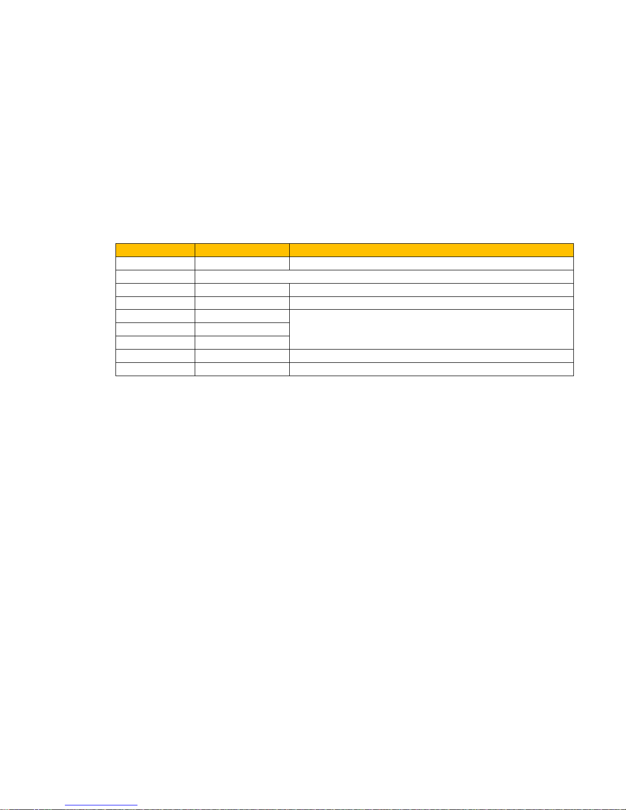
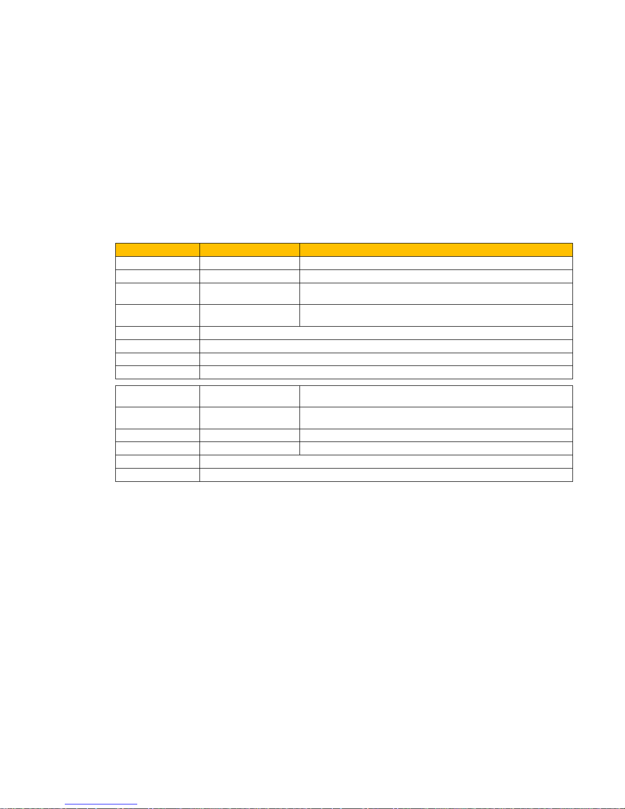
Inputs
Terminal Function Comment
ANIN 01 (X11/01)
SPEED SETPOINT
Speed Reference used when MANUAL RUN
ANIN 02 (X11/02)
Not used
DIGIN 01 (X13/02)
MANUAL RUN*
Run command for using the Analog Input as Setpoint
DIGIN 02 (X13/03)
AUTO RUN*
Run command for using the selected Preset Speed as Setpoint
DIGIN 03 (X13/04)
PRESET SELECT 1
These 3 digital input select the active Preset Speed if the Time Of Day Timer
feature is not being used
DIGIN 04 (X12/01)
PRESET SELECT 2
DIGIN 05 (X12/02)
PRESET SELECT 3
DIGIN 06 (X12/03)
NOT COAST STOP
When FALSE the Drive does not control Fan. The Fan will freewheel.
DIGIN 07 (X12/04)
NOT FIRE MODE
When FALSE activates Fire Mode
* If both Run inputs are TRUE, than MANUAL RUN has the highest priority.
www.comoso.com
Page 7
Fan Control Application Manual 5
AC30V series Variable Speed Drive
Outputs
Terminal Function Comment
ANOUT 01 (X11/03)
FAN SPEED DEMAND
Speed demand as % of maximum Fan speed
ANOUT 02 (X11/04)
FAN LOAD
Calculated fan load as % of maximum fan load
RELAY 0 1
(X14/01 & X14/02)
RUNNING When closed the Fan is being driven
RELAY 0 2
(X14/03 & X14/04)
NOT TRIPPED When closed the Drive is not tripped
DIGOUT 01 (X12/01)
Terminal used as DIGIN 04
DIGOUT 02 (X12/02)
Terminal used as DIGIN 05
DIGOUT 03 (X12/03)
Terminal used as DIGIN 06
DIGOUT 04 (X12/04)
Terminal used as DIGIN 07
RELAY 1 1
(X23/01 & X23/02)
FIRE MODE ACTIVATED When closed Fire Mode is currently Activated
RELAY 1 2
(X23/03 & X23/04)
FIRE MODE READY When closed Fire Mode is Ready for Activation
DIGOUT 11 (X20/01)
LOAD WARNING
Abnormal load detection low warning (belt slipping)
DIGOUT 12 (X20/02)
LOAD FAULT
Abnormal load detection low fault (belt broken)
DIGOUT 13 (X20/03)
Not used
DIGOUT 14 (X20/03)
Not used
www.comoso.com
Page 8

6 Fan Control Application Manual
AC30V series Variable Speed Drive
Graphical Keypad (GKP) Application Customisation
The fan application adds parameters and menus to the GKP. It also modifies behavior of the and set-up wi za rd.
Wizard
Under Quick Setup Application:
1960: Power Up Start
1958: Use Auto Timer
1959: Run When Non Zero SP
1962: Fire Mode Level
1961: Fire Mode Setpoint
2038: Setpoint Input Max
2039: Setpoint Input Min
Quick Setup
0486: Acceleration Time
0487: Deceleration Time
1916: Preset Speed 0
1917: Preset Speed 1
1918: Preset Speed 2
1919: Preset Speed 3
1920: Preset Speed 4
1921: Preset Speed 5
1922: Preset Speed 6
1923: Preset Speed 7
1958: Use Auto Timer
1959: Run When Non Zero SP
1006: Run Setup?
1141: View Level
www.comoso.com
Page 9

Fan Control Application Manual 7
AC30V series Variable Speed Drive
Quick Monitor
1997: Load Monitor State
0682: Reference
1924: Selected Preset
0500: Ramp Speed Output
0399: Actual Torque
1964: Fire Mode Activated
1965: Fire Mode Ready
Setup::Application and Monitor::Application
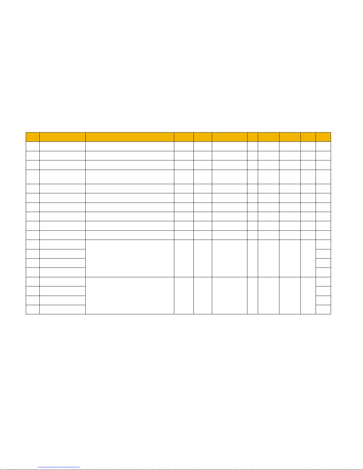
Include all parameters listed in the table at the end of this manual.
www.comoso.com
Page 10

8 Fan Control Application Manual
AC30V series Variable Speed Drive
Abnormal Load Detect
Setup::Application::Abnormal Load Detect
Monitor::Application::Abnormal Load Detect*
When used in the Fan Control Application this feature is used to detect low load indicating belt break or belt slip.
PNO
Parameter Descriptions
1968
Enable Load Monitor
Set TRUE to enable this feature.
1969
Startup Delay
This sets the duration from when the motor is started until the load monitoring is started. This allows for inaccurate speed/load
characterisation and load estim ation during start-up period.
1970
Fault Delay
This sets the duration from when the load monitor detects a LOAD FAULT until the sequencers stops the motor. This allows for
inaccurate speed/load characterisation and load estimation during start-up period.
1973
Low Warning Level
This specifies the deviation of the actual load below the expected load which will cause a LOAD LOW WARNING to be reported.
1974
Low Fault Level
This specifies the deviation of the actual load below the expected load which will cause a LOAD LOW FAULT to be reported.
1976
1977
1978
1979
Speed 1
Speed 2
Speed 3
Speed 4
These 4 parameters specify together with the 4 Load parameters below are used to characterise the expected load ‘curve’ for the
actual Speed.
1987
1988
1989
1990
Load 1
Load 2
Load 3
Load 4
See above Speed parameters.
www.comoso.com
Page 11

Fan Control Application Manual 9
AC30V series Variable Speed Drive
PNO
Parameter Descriptions
1997
Load Monitor State*
This diagnostic reports whether the monitor is monitoring and, if so, if the Load is as expected. This is an enumerated value:
0 MONITORING DISABLED
Either
Enable Load Monitor
is FALSE or
Speed 1
= 0.0%.
1 MONITORING STOPPED Motor not running, so not monitoring.
2 MONITORING STARTING
Motor started less than
Startup Delay
ago, so not monitoring yet.
3 LOAD NORMAL The actual Load is within the expected range, so anomaly detected.
5 LOAD LOW WARNING
The actual Load is below the
Low Warning Level
but not lower than the
Low Fault Level
.
7 LOAD LOW FAULT
The actual Load is below the Low Fault Level
1998
Expected Load*
This diagnostic is the calcul ated Load expected for the current Speed. This is determined from the load ‘curve’ specified by the Speed
n and Load n parameters and is useful for checking that in the case of incorrect warning or fault reporting.
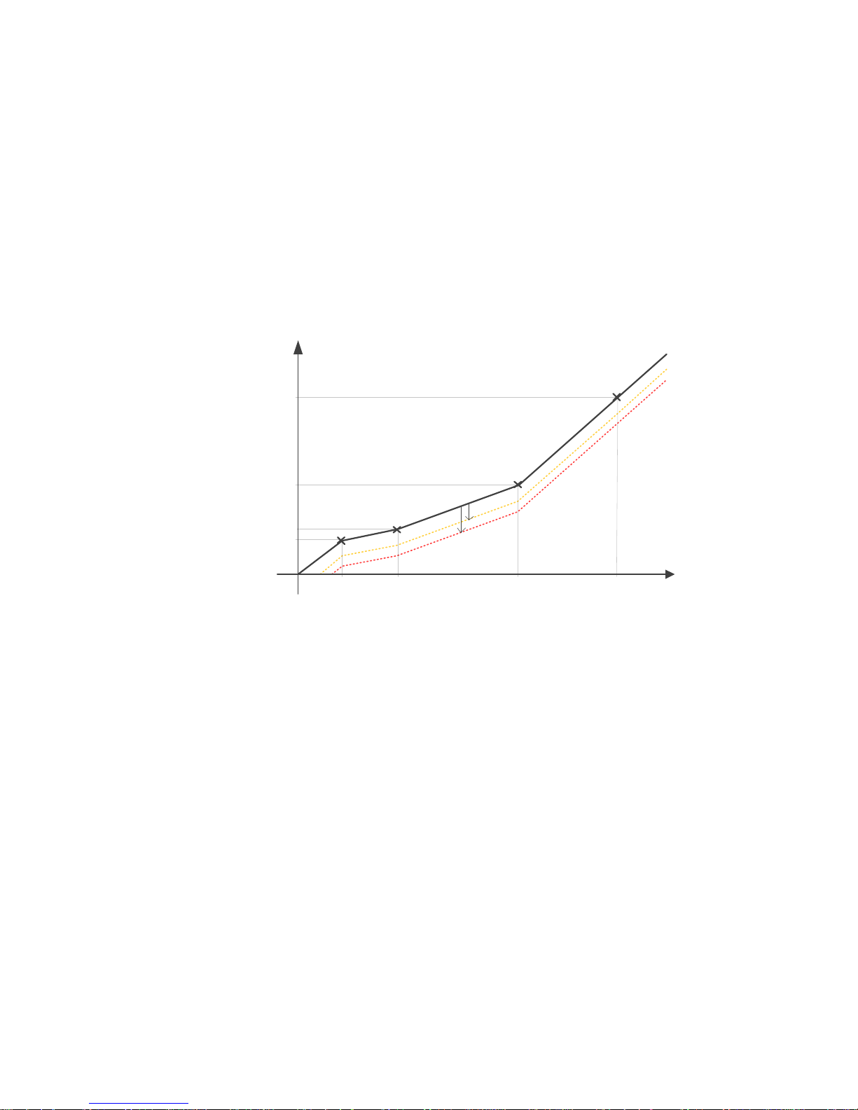
Functional Description
An estimate of the expected Load for any given Speed is specified using the Speed n and Load n parameters. Each pair provide a point on the
expected Load line.
The Speed parameters must have increasing values. I.e. Speed 1 < Speed 2 < Speed 3 < Speed 4.
If not all points are required, a Speed may be set to zero to terminate the sequence. If the actual speed is greater than the last specified point, the
line is extrapolated from the previous 2 points.
Speed 1 must be non-zero, otherwise the abnormal load detection feature is disabled.
www.comoso.com
Page 12
10 Fan Control Application Manual
AC30V series Variable Speed Drive
Load %
Speed %
Speed 1
Speed 2
Speed 3
Speed 4
Load
4
Load 3
Load 2
Load 1
Low Warning Level
Low Fault Level
Offset from the expected Load line, 2 additional lines are calculated. These are the Warning and Fault detection thresholds. The deviation from
normal behavior is determined by the Low Warning Level and Low Fault Level parameters.
When running, the Load Monitor State diagnostic will show if the actual Load is in the NORMAL, WARNING or FAULT region of the graph. Note
– for this to report correctly, the Low Fault Level must be more negative than the Low Warning Level.
If the actual Load remains in the FAULT region for longer than the duration specified by Fault Delay, the Drive will stop running.
The Start Delay may be used to prevent incorrect warning or fault reported soon after the Run command is issued.
The Load Monitor State diagnostic is reset when the Run command is removed.
www.comoso.com
Page 13
Fan Control Application Manual 11
AC30V series Variable Speed Drive
Fire Mode
Setup::Application::Fire Mode
Monitor::Application::Fire Mode*
Fire mode is intended for use in critical situations where it is imperative for the motor to be kept running if at all possible. In such a situation it may
be reasonable to override the Drives’ normal protective functions. An example of a critical situation may be a ventilation fan in a stairwell, where
continued operation in the event of a fire may assist the safe evacuation of personnel.
Caution When Fire Mode is active the Drive and Motor protection trips are disabled. The use of Fire Mode itself increases the risk of causing
a fire by overloading the drive or motor, so it must only be used after assessing the risks.
PNO
Parameter Descriptions
Fire Mode Activate
Set TRUE to activate the Fire Mode feature. This input may only be set by connection to a digital input as part of the application.
1961
Fire Mode Setpoint
A reference value to be used when Fire Mode is active. Setting a negative setpoint will cause the drive to rotate in reverse direction.
1962
Fire Mode Level
This parameter selects the mode of operation when Fire Mode is activated. It is an enumerated value as follows:
0
DISABLED
Fire Mode feature is disabled. The
Activate
input going high will have no effect.
1 PARTIAL Fire Mode is enabled with “partial mode” trips listed below ignored.
2 FULL Fire Mode is enabled with “full mode” trips listed below ignored.
1963
FM Restart Delay
This specifies the duration to wait before attempting to reset a trip.
1964
Fire Mode Activated
When TRUE, this diagnostic, indicates that the Fire Mode is in operation. Trips are being ignored at either the PARTIAL or FULL level
and the fire mode Setpoint, which is non-zero, is being followed.
1965
Fire Mode Ready
This diagnostic, when TRUE, indicates that the Fire Mode will operate if the Activate input becomes TRUE. The diagnostic will be
FALSE if the fire mode Level is set to DISABLED or the fire mode Setpoint is set to 0.0%.
www.comoso.com
Page 14
12 Fan Control Application Manual
AC30V series Variable Speed Drive
PNO
Parameter Descriptions
1966
FM Last Activated
A Data and Time diagnostic that records the last time that the Fire Mode was activated. This may be used to validate that the fire mode
has been tested. The value is preserved in non-volatile memory. A Real Time Clock (RTC) option must be fitted for the timestamp.
1967
FM Activation Count
This diagnostic records the number of activations of the fire mode. This may be used to validate that the fire mode has been tested.
The value is preserved in non-volatile memory.
Functional Description
When Fire Mode is activated, the Drive will attempt to run at the speed set by the Fire Mode Setpoint parameter even if the Drive was not
running at the time. This is regardless of whether in Remote or Local sequencing mode.
Caution If the Drive is powered-up with the Activate input TRUE, the Drive will run immediately without warning.
The only reasons that the drive will not run are:
• Level is set to DISABLED
• Setpoint is zero
• The Coast Stop input is activated.
• The STO circuit is activated.
• An enabled trip source becomes active.
•
A hardware fault
Caution
Fire Mode does not override the standard Ramp features. Specifically 0497 Ramp Hold can prevent the setpoint changing to the Fire
Mode Setpoint value.
The following table summarizes which trips are disabled in the two modes of operation. Also shown are those trips which are designed to protect
the drive.
Caution Disabling the Drive Protection trips will invalidate the drive’s warranty.
Selecting PARTIAL mode leaves the drive protection features enabled. Selecting FULL mode disables some of the drive protection
features.
Caution Regardless of the setting of Level, activating Fire Mode may cause damage to the motor or attached equipment.
www.comoso.com
Page 15

Fan Control Application Manual 13
AC30V series Variable Speed Drive
ID
Trip Name
Disabled in Partial mode
Disabled in Full mode
Drive Protection
1
OVER VOLTAGE
2
UNDER VOLTAGE
(1)
Note 1
Note 1
3
OVER CURRENT
4
STACK FAULT
5
STACK OVER CURRENT
6
CURRENT LIMIT
7
MOTOR STALL
8
INVERSE TIME
9
MOTOR I2T
10
LOW SPEED I
11
HEATSINK OVERTEMP
12
AMBIENT OVERTEMP
13
MOTOR OVERTEMP
14
EXTERNAL TRIP
15
BRAKE SHORT CCT
16
BRAKE RESISTOR
17
BRAKE SWITCH
18
LOCAL CONTROL
19
COMMS BREAK
20
LINE CONTACTOR
21
PHASE FAIL
22
VDC RIPPLE
23
BASE MODBUS BREAK
24
24V OVERLOAD
25
PMAC SPEED ERROR
26
OVERSPEED
27
SAFE TORQUE OFF
Note 1. The Under Voltage trip is enabled when Fire Mode is active, but the trip level is reduced by 50%.
If a trip source becomes active when the associated trip is disabled the drive will continue to run. This is also the normal behavior of the drive,
(when Fire Mode is not active). If the associated trip is designed for drive protection, this will be recorded in non-volatile memory. The recorded
values are available to view in the Drives’ Trips History.
When Fire Mode is activated and a trip source becomes active and the associated trip is enabled, the Drive will trip, causing the motor to stop.
This is similar to the normal behavior of the Drive, (when Fire Mode is not active). However, when Fire Mode is active the firmware within the
Drive continues to monitor the trip source, once the trip source has become inactive the drive automatically resets the trip condition and restarts
the drive.
www.comoso.com
Page 16
14 Fan Control Application Manual
AC30V series Variable Speed Drive
Preset Speeds
Setup::Application::Preset Speeds
Setup::Application::Preset Speeds*
The Fan Control Application allows this feature to be either used directly from digital inputs or in conjunction with the Time Of Day Timer.
The Presets function selects 1 of 8 values to be used as a reference.
PNO
Parameter Descriptions
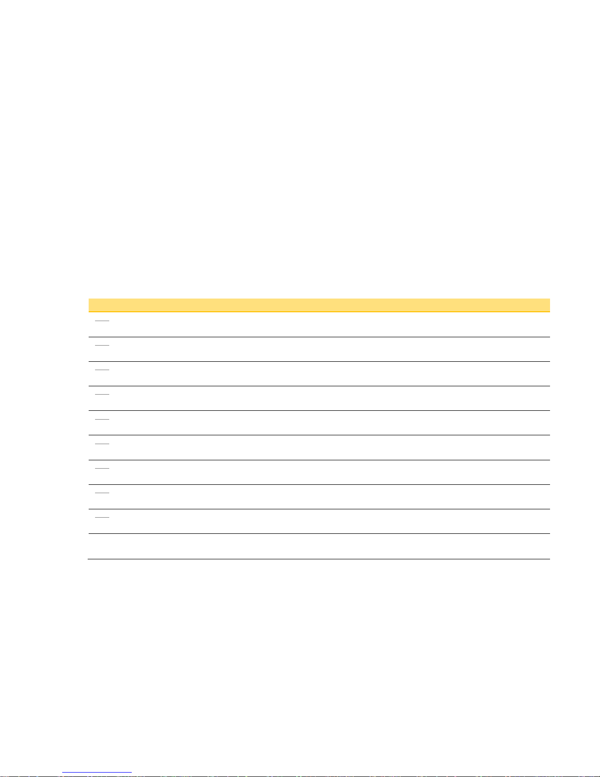
1916
Preset Speed 0
Preset Speed Output when Selected Preset equals 0
1917
Preset Speed 1
Preset Speed Output when Selected Preset equals 1
1918
Preset Speed 2
Preset Speed Output when Selected Preset equals 2
1919
Preset Speed 3
Preset Speed Output when Selected Preset equals 3
1920
Preset Speed 4
Preset Speed Output when Selected Preset equals 4
1921
Preset Speed 5
Preset Speed Output when Selected Preset equals 5
1922
Preset Speed 6
Preset Speed Output when Selected Preset equals 6
1923
Preset Speed 7
Preset Speed Output when Selected Preset equals 7
1924
Selected Preset*
Diagnostic showing selected preset number
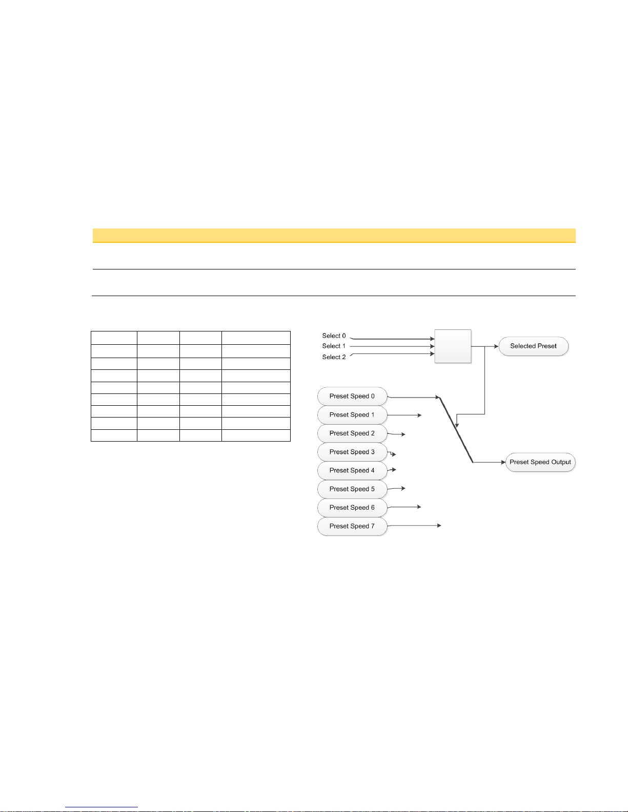
Select 0
This is connected to a Digital Input as part of the selected macro. It provides bit 0 of the Selected Preset number.
www.comoso.com
Page 17
Fan Control Application Manual 15
AC30V series Variable Speed Drive
PNO
Parameter Descriptions
Select 1
This is connected to a Digital Input as part of the selected macro. It provides bit 1 of the Selected Preset number.
Select 2
This is connected to a Digital Input as part of the selected macro. It provides bit 2 of the Selected Preset number.
Functional Description
Select 2 Select 1 Select 0 Selected Preset
FALSE FALSE FALSE Preset Speed 0
FALSE FALSE TRUE
Preset Speed 1
FALSE TRUE FALSE
Preset Speed 2
FALSE FALSE FALSE
Preset Speed 3
TRUE FALSE TRUE
Preset Speed 4
TRUE TRUE FALSE
Preset Speed 5
TRUE FALSE FALSE
Preset Speed 6
TRUE FALSE FALSE
Preset Speed 7
www.comoso.com
Page 18

16 Fan Control Application Manual
AC30V series Variable Speed Drive
Reference
Setup::Application::Reference
The Fan Control Application provides 2 parameters to scale and offset the Setpoint analog input.
PNO
Parameter Descriptions
2038
Setpoint Input Max
Sets the full range value for the Setpoint analogue input (ANIN01). It corresponds to the maximum input value of either 10V or 20mA
depending on the setting of
0001: Anin 01 Type.
2039
Setpoint Input Min
Sets the minimum value for the Setpoint analogue input (ANIN01). It corresponds to the minimum input value of either -10V, 0V, 0mA
or 4mA depending on the setting of
0001:
Anin 01 Type
.
Functional Description
setpoint = ((input / 100) x (Setpoint Input Max – Setpoint Input Min)) + Setpoint Input Min
www.comoso.com
Page 19
Fan Control Application Manual 17
AC30V series Variable Speed Drive
Sequencing
Setup::Application::Sequencing
The Fan Control Application introduces 3 additional sequencing parameters.
PNO
Parameter Descriptions
1959
Use Auto Timer
When TRUE, the AUTO RUN Preset Speed is selected by the Time Of Day Timer function. When FALSE (the default), the Preset
Speed is selected by digital inputs.
1960
Start On Setpoint
When TRUE and either AUTO RUN or MANUAL RUN is TRUE, the Drive will automatically run whenever the active Setpoint is nonzero.
1961
Power Up Start
When TRUE the Drive will immediately run on power up if the AUTO RUN or MANUAL RUN digital input is TRUE. If this parameter is
FALSE (the default) a FALSE to TRUE transition of the RUN input is required.
Functional Description
Use Auto Timer:
This allows Time Of Day Timer to override the digital inputs for the selection of the Preset Speed.
Start On Setpoint:
This feature removes the need of applying a run command. Whenever a non-zero (±0.5%) becomes active from either the Preset Speeds or
Analog input, a run command is automatically issued.
Caution The Drive may run without warning.
Power Up Start:
This feature removes the requirement of a transition from FALSE to TRUE on the run command. This allows an immediate start of the motor
when power is applied to the Drive.
Caution The Drive may run without warning.
www.comoso.com
Page 20

18 Fan Control Application Manual
AC30V series Variable Speed Drive
Skip Frequencies
Setup::Application::Skip Frequencies
When used in the Fan Control Application a maximum of 2 skip frequencies are available for use.
This function is used to prevent the Drive operating at frequencies that cause mechanical resonance in the load.
PNO
Parameter Descriptions
1908
Skip Freq Band 1
The width of skip band 1 in Hz.
1909
Skip Frequency 1
The centre frequency of skip band 1 in Hz.
1910
Skip Freq Band 2
The width of skip band 2 in Hz.
1911
Skip Frequency 2
The centre frequency of skip band 2 in Hz.
Functional Description
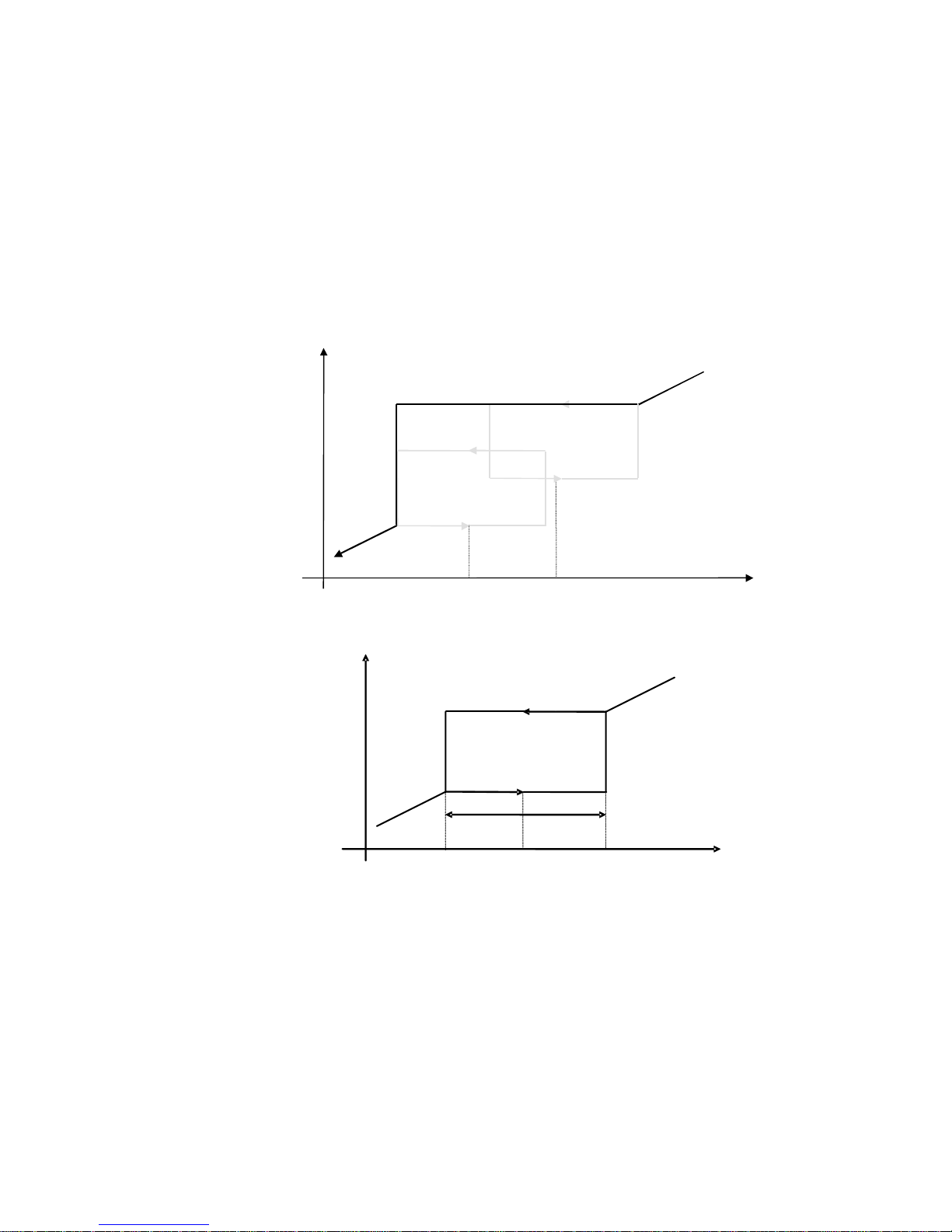
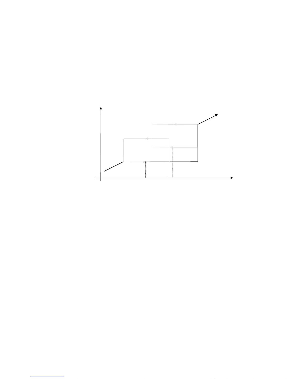
Skip frequencies are used to avoid resonances within the mechanical system. Enter the value of frequency that causes the resonance using a
Frequency parameter and then program the width of the skip band using its Band parameter. The Drive will then avoid sustained operation
within the forbidden band as shown in the diagram. The skip frequencies are symmetrical and thus work in forward and reverse.
Setting a Frequency to 0.0 disables the corresponding band. Setting a Band to 0.0 causes the value of Band 1 to be used for this band.
www.comoso.com
Page 21
Fan Control Application Manual 19
AC30V series Variable Speed Drive
Setpoint
Drive
Frequency
Frequency 1 Frequency 2
The behaviour of this function is illustrated below.
Skip band
Skip Frequency
Setpoint
Drive
Frequency
www.comoso.com
Page 22
20 Fan Control Application Manual
AC30V series Variable Speed Drive
Setpoint
Drive
Frequency
Frequency 1
Frequency 2
www.comoso.com
Page 23

Fan Control Application Manual 21
AC30V series Variable Speed Drive
Time Of Day Timer
Setup::Application::Time Of Day Timer
Monitor::Application::Time Of Day Timer*
This feature allows preset speeds to be selected depending on the time of day and day of week. It requires a Real Time Clock (RTC) to operate,
so an IO Option type 7004-01-00 or 7004-03-00 must be fitted.
When used in the Fan Control Application a maximum of 8 speed select events are available for use.
PNO
Parameter Descriptions
2002
2003
2004
2005
2006
2007
2008
2009
Event Days 1
Event Days 2
Event Days 3
Event Days 4
Event Days 5
Event Days 6
Event Days 7
Event Days 8
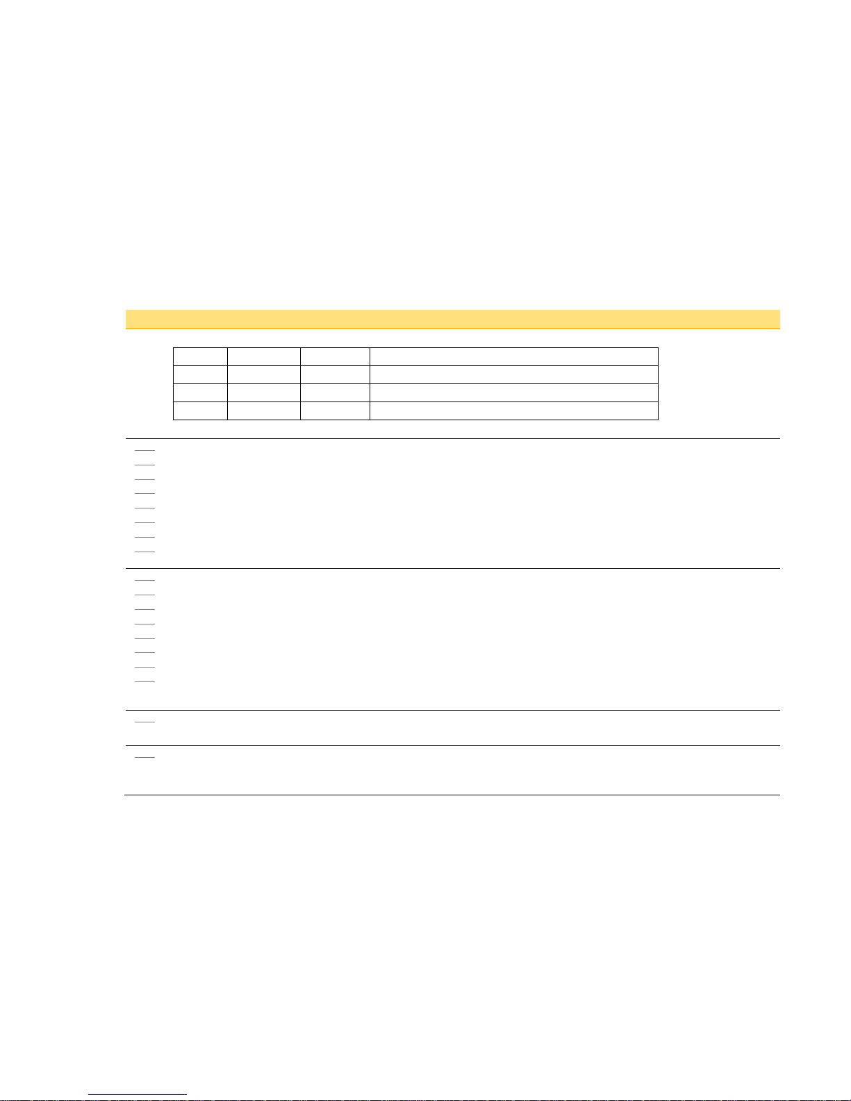
These 8 parameters specify which day, or days, the event 1-6 applies. Each day is represented as a bit, so that when set indicates that
the event is valid on that day. More than one bit may be set to indicate the event is valid on more than one day.
Bit Hexadecimal Decimal Day Of Week
0 01 1 SUNDAY
1 02 2 MONDAY
2 04 4 TUESDAY
3 08 8 WEDNESDAY
4 10 16 THURSDAY
5 20 32 FRIDAY
6 40 64 SATURDAY
www.comoso.com
Page 24
22 Fan Control Application Manual
AC30V series Variable Speed Drive
PNO
Parameter Descriptions
Example multiple day events:
Bits Hexadecimal Decimal Days Of Week
0,6 41 65 SATURDAY, SUNDAY
1,2,3,4,5 3E 62 MONDAY, TUESDAY, WEDNESDAY, THURSDAY, FRIDAY
0-7 7F 127 Every Day
A value of 0 disables the event.
2013
2014
2015
2016
2017
2018
2019
2020
Event Time Of Day 1
Event Time Of Day 2
Event Time Of Day 3
Event Time Of Day 4
Event Time Of Day 5
Event Time Of Day 6
Event Time Of Day 7
Event Time Of Day 8
These 8 parameters specify the time of day the event 1-6 occurs.
2024
2025
2026
2027
2028
2029
2030
2031
Event Select 1
Event Select 2
Event Select 3
Event Select 4
Event Select 5
Event Select 6
Event Select 7
Event Select 8
These 8 parameters specify the Selected value when the event 1-6 occurs. This value is maintained until the next timed event occurs.
It can be set to any value between 0 and 7 which then is used to select the Preset Speed to be used when the event is active.
2034
Selected*
This diagnostic is the Event Select value for the Active Event . If there are no programmed events this will be set to 0.
2035
Day Of Week Now*
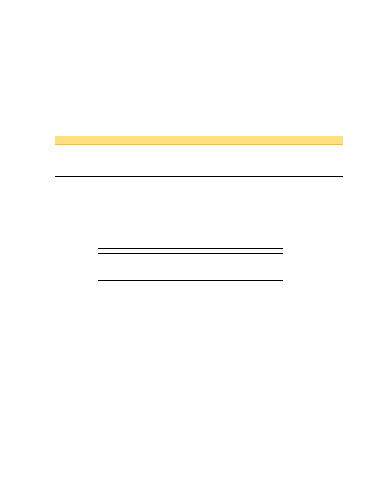
This diagnostic is the day of the week today as determined by the Real Time Clock (RTC). This is an enumerated value:
0 SUNDAY
www.comoso.com
Page 25
Fan Control Application Manual 23
AC30V series Variable Speed Drive
PNO
Parameter Descriptions
1 MONDAY
2 TUESDAY
3 WEDNESDAY
4 THURSDAY
5 FRIDAY
6 SATURDAY
2037
Active Event*
This diagnostic indicates which of the speed change events last occurred (and is still active). If there are no programmed events this
will be set to 0.
Functional Description
A maximum of 6 events may be programmed. Each event is for a time of day on one or more days of the week. A value to be selected is then
chosen to be output when the time of day is reached on one of the days that have been specified.
So, each event is programmed with 3 parameters. These are Event Days, Event Time Of Day and Event Select. Unused events must have
their Event Days set to 0 (default). Events do not need to be declared in chronological order and unused events do no need to be last (i.e. gaps
are allowed).
Example Program:
n
Event Days n
Event Time Of Day n
Event Select n
1
3E (Mon, Tues, Wed, Thurs, Fri)
7:00
1
2
40 (Sat)
8:30
1
3
7F (Sun, Mon, Tues, Wed, Thurs, Fri, Sat)
11:00
2
4
7E (Mon, Tues, Wed, Thurs, Fri, Sat)
14:00
3
5
01 (Sun)
14:00
0
6
7E (Mon, Tues, Wed, Thurs, Fri, Sat)
18:00
0
This then has the following behavior:
- Monday to Friday the Preset Speed 1 is selected at 7:00. This remains selected until 11:00 when the Preset Speed 2 is selected. At
14:00 it is changed to Preset Speed 3. Finally, at 18:00 Preset Speed 0 is selected.
- Saturday is the same as Monday to Friday except that the selecting of Preset Speed 1 occurs later at 8:30.
- On Sunday the program just selects Preset Speed 2 at 11:00 and th en Pres et Speed 0 at 14:00
At power-up, the Time Of Day Timer searches backwards in time (and day) to find the Event that would be active if the power had been on
continuously. It then makes this Event active. In the example above, if power-up was 10:00 on SATURDAY then Event 2 would be active, but if at
10:00 on a SUNDAY then Event 6 would be active.
www.comoso.com
Page 26

24 Fan Control Application Manual
AC30V series Variable Speed Drive
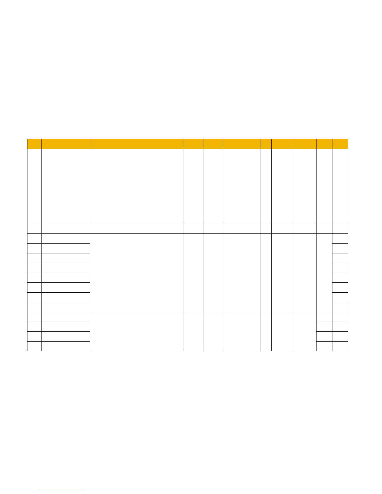
PNO Name Path(s) Type Default Range
Units
WQ View Notes MBus
1901
Selected Application Setup::Application::App Selection
USINT
(enum)
0
0: FAN
CONTROL
CONFIG
04329
1908
Skip Band 1 Setup::Application::Skip Frequencies REAL 0.0 0.0 to 1000.0 Hz ALWAYS
04343
1909
Skip Frequency 1 Setup::Application::Skip Frequencies REAL 0.0 0.0 to 1000.0 Hz ALWAYS
04345
1910
Skip Band 2 Setup::Application::Skip Frequencies REAL 0.0 0.0 to 1000.0 Hz ALWAYS
04347
1911
Skip Frequency 2 Setup::Application::Skip Frequencies REAL 0.0 0.0 to 1000.0 Hz ALWAYS
04349
1916
Preset Speed 0
Setup::Application::Preset Speeds REAL 0.0 -100.0 to 100.0 % ALWAYS
04359
1917
Preset Speed 1 04361
1918
Preset Speed 2 04363
1919
Preset Speed 3 04365
1920
Preset Speed 4 04367
1921
Preset Speed 5 04369
1922
Preset Speed 6 04371
1923
Preset Speed 7 04373
1924
Selected Preset Monitor::Application::Preset Speeds USINT 0 0 to 7 NEVER
04475
1958
Use Auto Timer Setup::Application::Sequencing BOOL FALSE ALWAYS
04445
1959
Start On Setpoint Setup::Application::Sequencing BOOL FALSE ALWAYS
04447
1960
Power Up Start Setup::Application::Sequencing BOOL FALSE ALWAYS
04449
1961
Fire Mode Setpoint Setup::Application::Fire Mode REAL 0.0 -100.0 to 100.0 % ALWAYS
04451
1962
Fire Mode Level Setup::Application::Fire Mode
USINT
(enum)
0
0:DISABLED
1:PARTIAL
2:
FULL
ALWAYS
04453
www.comoso.com
Page 27
Fan Control Application Manual 25
AC30V series Variable Speed Drive
PNO Name Path(s) Type Default Range
Units
WQ View Notes MBus
1963
FM Restart Delay Setup::Application::Fire Mode TIME 2 0 to 600 s ALWAYS
04455
1964
Fire Mode Activated Monitor::Ap pl icat ion: :F ire Mode BOOL FALSE NEVER
04455
1965
Fire Mode Ready Monitor::Application::Fire Mode BOOL FALSE NEVER
04457
1966
FM Last Activated Monitor::Application::Fire Mode
DATE_A
ND_TIME
NEVER
04459
1967
FM Activation Count Monitor::Application::Fire Mode UINT 0 0 to 65535 NEVER
04459
1968
Enable Load Monitor Setup::Application::Abnormal Load Detect BOOL 0 NEVER
04463
1969
Startup Delay Setup::Application::Abnormal Load Detect TIME 10 s ALWAYS
04465
1970
Fault Delay Setup::Application::Abnormal Load Detect TIME 1 s ALWAYS
04467
1973
Low Warning Level Setup::Application::Abnormal Load Detect REAL -100.0 -100.0 to 0.0 % ALWAYS
04473
1974
Low Fault Level Setup::Application::Abnormal Load Detect REAL -100.0 -100.0 to 0.0 % ALWAYS
04475
1976
Speed 1
Setup::Application::Abnormal Load Detect REAL 0.0 0.0 to 100.0 % ALWAYS
04479
1977
Speed 2 04481
1978
Speed 3 04483
1979
Speed 4 04485
1987
Load 1
Setup::Application::Abnormal Load Detect REAL 0.0 0.0 to 100.0 % ALWAYS
04501
1988
Load 2 04503
1989
Load 3 04505
1990
Load 4 04507
www.comoso.com
Page 28
26 Fan Control Application Manual
AC30V series Variable Speed Drive
PNO Name Path(s) Type Default Range
Units
WQ View Notes MBus
1997
Load Monitoring State Monitor::Application::Abnormal Load Detect
USINT
(enum)
0
0:MONITORING
DISABLED
1:
MONITORING
STOPPED
2:
MONITORING
STARTING
3:
LOAD
NORMAL
5:
LOAD LOW
WARNING
7:
LOAD LOW
FAULT
ALWAYS
04521
1998
Expected Load Monitor::Application::Abnormal Load Detect
REAL 0.0 0.0 to 100.0 % NEVER
04523
2002
Event Days 1
Setup::Application::Time Of Day Timer
BYTE
(bitfield)
00
0:Sunday
1:Monday
2:Tuesday
3:Wednesday
4:Thursday
5:Friday
6:Saturday
ALWAYS
04531
2003
Event Days 2 04533
2004
Event Days 3 04535
2005
Event Days 4 04537
2006
Event Days 5 04539
2007
Event Days 6 04541
2008
Event Days 7 04543
2009
Event Days 8 04545
2013
Event Time Of Day 1
Setup::Application::Time Of Day Timer
TIME_OF
_DAY
0:00:00
0:00:00 to
23:59:59
ALWAYS
04553
2014
Event Time Of Day 2 04555
2015
Event Time Of Day 3 04557
2016
Event Time Of Day 4 04559
www.comoso.com
Page 29
Fan Control Application Manual 27
AC30V series Variable Speed Drive
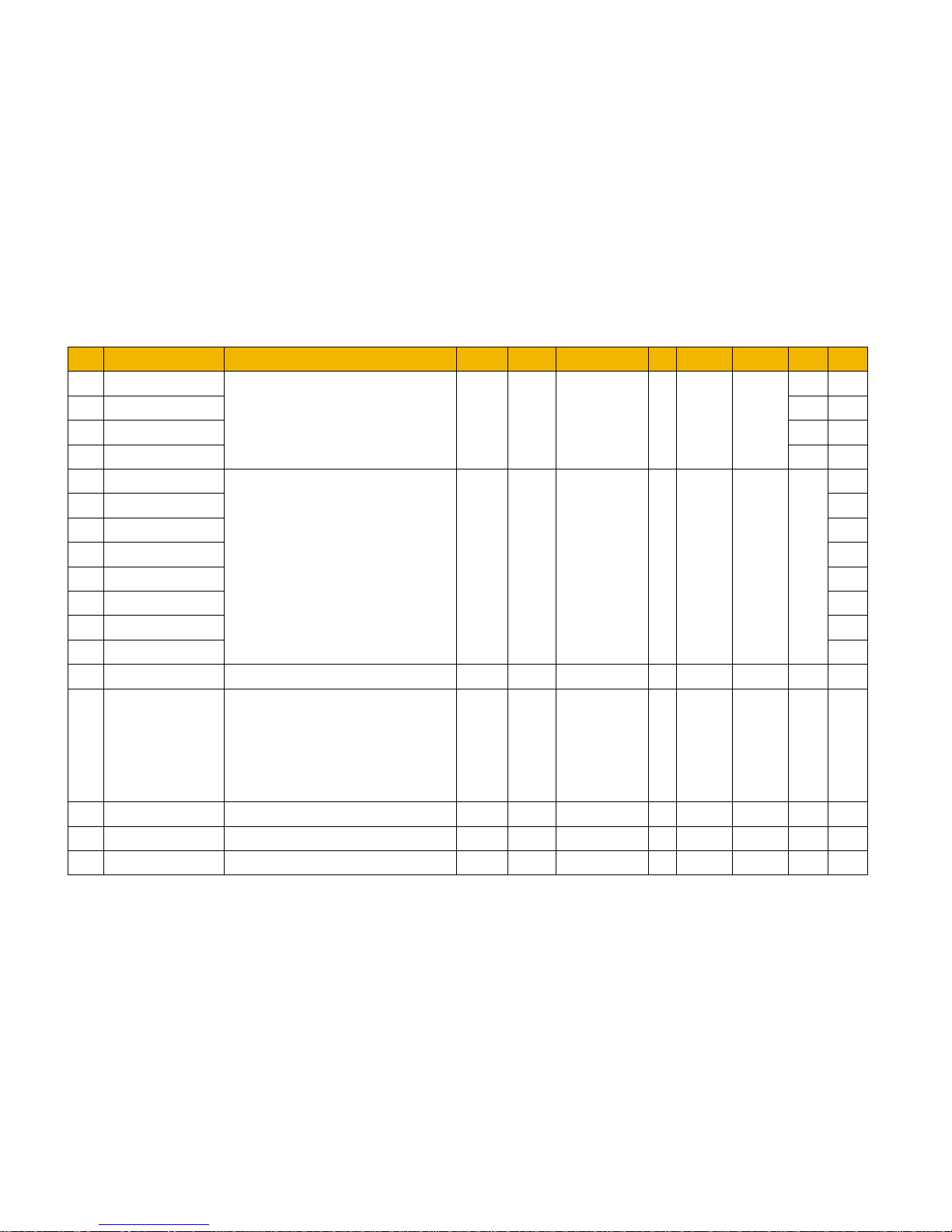
PNO Name Path(s) Type Default Range
Units
WQ View Notes MBus
2017
Event Time Of Day 5 04561
2018
Event Time Of Day 6 04563
2019
Event Time Of Day 7 04565
2020
Event Time Of Day 8 04567
2024
Event Select 1
Setup::Application::Time Of Day Timer USINT 0 0 to 7 ALWAYS
04575
2025
Event Select 2 04577
2026
Event Select 3 04579
2027
Event Select 4 04581
2028
Event Select 5 04583
2029
Event Select 6 04585
2030
Event Select 7 04587
2031
Event Select 8 04589
2034
Selected Monitor::Application::Time Of Day Timer USINT NEVER
04595
2035
Day Of Week Now Monitor::Application::Time Of Day Timer
USINT
(enum)
0
0:SUNDAY
1:MONDAY
2:TUESDAY
3:WEDNESDAY
4:THURSDAY
5:FRIDAY
6:SATURDAY
NEVER
04597
2037
Active Event Monitor::Application::Time Of Day Timer USINT 0 0 to 6 NEVER
04601
2038
Setpoint Input Max Setup::Application::Reference REAL 100.00 -200.00 to 200.00
ALWAYS
04417
2039
Setpoint Input Min Setup::Application::Reference REAL 0.00 -200.00 to 200.00
ALWAYS
04419
www.comoso.com
Page 30

AE – UAE, Dubai
Tel: +971 4 8127100
[email protected]
AR – Argentina, Buenos Aires
Tel: +54 3327 44 4129
AT – Austria, Wiener Neustadt
Tel: +43 (0)2622 23501-0
[email protected]
AT – Eastern Eu rope,
Wiener Neustadt
Tel: +43 (0)2622 23501 900
[email protected]
AU – Austr alia, Castle Hill
Tel: +61 (0)2-9634 7777
AZ – Aze rbaija n, Baku
Tel: +994 50 2233 458
[email protected]
BE/LU – Belgium, Nivelles
Tel: +32 (0)67 280 900
[email protected]
BR – Braz il, Cachoeirinha RS
Tel: +55 51 3470 9144
BY – Belaru s, Minsk
Tel: +375 17 209 9399
[email protected]
CA – Canada , Milton, Ontario
Tel: +1 905 693 300 0
CH – Switzerland, Etoy
Tel: +41 (0)21 821 87 00
[email protected]
CL – Chile , Santiago
Tel: +56 2 623 1216
CN – China , Shanghai
Tel: +86 21 2899 5000
CZ – Czech Rep ublic , Klecany
Tel: +420 284 083 111
[email protected]
DE – Germa ny, Kaarst
Tel: +49 (0)2131 4016 0
[email protected]
DK – Denma rk, Ballerup
Tel: +45 43 56 04 00
[email protected]
ES – Spai n, Madrid
Tel: +34 902 330 001
[email protected]
FI – Finla nd, Van taa
Tel: +358 (0)20 753 2500
parker.[email protected]
FR – France, Contamine s/Arve
Tel: +33 (0)4 50 25 80 25
[email protected]
GR – Gree ce, Athens
Tel: +30 210 933 6450
[email protected]
HK – Hong Kong
Tel: +852 2428 8008
HU – Hunga ry, Budapest
Tel: +36 1 220 4155
[email protected]
IE – Irela nd, Dublin
Tel: +353 (0)1 466 6370
[email protected]
IN – India , Mumbai
Tel: +91 22 6513 7081-85
IT – Italy, Corsico (MI)
Tel: +39 02 45 19 21
[email protected]
JP – Japan , Tok yo
Tel: +81 (0)3 6408 3901
KR – Sout h Korea, Seoul
Tel: +82 2 559 0400
KZ – Kaza khst an, Almaty
Tel: +7 7272 505 800
[email protected]
MX – Mexico , Apodaca
Tel: +52 81 8156 6000
MY – Malay sia, Shah Alam
Tel: +60 3 7849 0800
NL – The Net herla nds,
Oldenzaal
Tel: +31 (0)541 585 000
[email protected]
NO – Norw ay, Asker
Tel: +47 66 75 34 00
[email protected]
NZ – New Zeal and, Mt
Wellington
Tel: +64 9 574 1744
PL – Poland , Warsaw
Tel: +48 (0)22 573 24 00
[email protected]
PT – Port ugal, Le ca da
Palmeira
Tel: +351 22 999 7360
[email protected]
RO – Romani a, Bucharest
Tel: +40 21 252 1382
[email protected]
RU – Russi a, Moscow
Tel: +7 495 645-2156
[email protected]
SE – Swede n, Spånga
Tel: +46 (0)8 59 79 50 00
[email protected]
SG – Singa pore
Tel: +65 6887 6300
SK – Slovak ia, Banská Bystrica
Tel: +421 484 162 252
[email protected]
SL – Sloven ia, Novo Me sto
Tel: +386 7 337 6650
[email protected]
TH – Thailand, Bangkok
Tel: +662 717 8140
TR – Turkey, Istanbul
Tel: +90 216 4997081
[email protected]
TW – Taiwan, Taipei
Tel: +886 2 2298 8987
UA – Ukrain e, Kiev
Tel +380 44 494 2731
[email protected]
UK – Unite d Kingd om,
Warwi ck
Tel: +44 (0)1926 317 878
[email protected]
US – USA, Cleveland
Tel: +1 216 896 3000
VE – Venezue la, Caracas
Tel: +58 212 238 5422
ZA – Sout h Afric a,
Kempton Pa rk
Tel: +27 (0)11 961 0700
[email protected]
Parker Worldwide
Parker Hannifin Manufacuring Limited
Automation Group, SSD Drives Europe,
New Courtwick Lane,
Littlehampton, West Sussex. BN17 7RZ
Office: +44 (0)1903 737000
Fax: +44 (0)1903 737100
www.parker.com/ssd
European Product Information Centre
Free phon e: 00 80 0 27 27 5374
(from AT, BE, CH, CZ , DE, EE , ES, FI, F R, IE, IL , IS, IT,
LU, MT, NL, NO, PT, SE, SK , UK)
*HA502134U002_02*
www.comoso.com
 Loading...